The FREEDM System: components, main functions, system control · PDF file ·...
36
1 Short course on the FREEDM System Session L3 The FREEDM System: components, main functions, system control Dr. I. Husain, North Carolina State University Dr. G. T. Heydt, Arizona State University October 26, 2016
Transcript of The FREEDM System: components, main functions, system control · PDF file ·...

1
Short course on the FREEDM System
Session L3
The FREEDM System: components, main functions, system control
Dr. I. Husain, North Carolina State UniversityDr. G. T. Heydt, Arizona State University
October 26, 2016

Topics for this tutorial
2
Lecture L3
A. Traditional distribution systems, strengths, weaknesses
B. Overview of the FREEDM system and components
C.FREEDM system control and comparison with traditional
systems
D.Some features of the distribution system of the future:
pricing, cost / benefit, reliability
FREEDM Vision
Centralized
Generation
FREEDM
Isolation
Device
Energy
Router
Energy
Cell
Intelligence
Energy
InternetToday
Distributed Resources
Intermittency
2
Energy
Cell=Load,
Generation
& Storage

Bi-directional flow
1. Solid State Transformer
4
Storage DG
2. Plug-and-play DC or AC Microgrid (Energy Cell)
1. Fault Isolation Device
120V/240V AC
StorageDG
3. Information Technology
4. Robust and Automated Power, Energy and Fault Management
The FREEDM Solution
380V DC BUS

FREEDM System Scalability
SST
LO
AD D
ES
DD
RE
R
Distribution Feeder
Local Field Area Network
RS
C
RS
C
SST
LO
AD D
ES
DD
RE
R
DGI
RS
C
Enterprise Wide Area Network
SCADA and Centralized Applications
DGI
FID
DGI
RC
S
System can be as small as one SSTAdd Distributed Generation and StorageAdd 2nd SST
Add FIDLink SSTs using peer to peer RSC
Interface FREEDM System to Utility
• Power distribution system built from ground up using
FREEDM System devices.
5DGI: Distributed Grid Intelligence SST: Solid State Transformer FID: Fault Isolation Device

6
SST Enabled Smart Grid Features
•Fault management•Current limiting•Disconnect/reconnect
•Power Management:•Control power factor•Change/Control customer voltage •Provide DC power•Eliminate harmonics•Low voltage ride through•Supports multiple islanding modes
•Energy Management•Monitor energy usage (AMI)•Can control/dispatch power via
microgrids (Energy Cell)
•Demand side management
Microsecond
Hours
SST
Utility Distribution Feeder
LVDC 380V
LVAC 120/240V
SoftwareCommunication
(IEC61850, DNP3,
Modbus …)
co
ntr
ol
Features demonstrated in GEH using Gen I &II SSTs

FREEDM Physical Level Definitions
DESD
DC/DC
Battery
DRER
DC/AC
AC Gen
DRER
DC/DC
PV
L1 – Energy Cell
L2 – SST
L3 – FREEDM
L4 – Multiple Systems
1 MVA SST
1 MVA SST
1 MVA SST
Load
SST
Legend
12 kV-AC
Communication
380 V-DC
120 V-AC
L1 – Energy Cell
L2 – SST
DRER
DC/DC
PV
DRER
DC/AC
AC Gen
DESD
DC/DC
Battery Load
FID FID
SST
Level 1 – Energy Cell (Microgrid)
Coordination of local load,
generation, and storage on SST
secondary for maintaining
instantaneous power balance.
Level 2 – Single SST
Interaction of a single SST with
medium-voltage FREEDM system
based on localized measurements
and control.
Level 3 – FREEDM System
Interaction of multiple SSTs and FIDs
within a single FREEDM system
based on peer to peer
communications and distributed
control. Note “1 MVA SST”
corresponds to Substation SST.
Level 4 – Multiple FREEDM Systems
Interaction of multiple FREEDM
systems interconnected to form a
medium-voltage distribution
system.

FREEDM Use Cases
• UC1: Plug and Play Functionality
• UC2: IEM when FREEDM System is Grid Connected
• UC3: IEM when FREEDM System is Islanded
• UC4: IEM when SST is Islanded
• UC5: IPM when FREEDM System is Grid Connected
• UC6: IPM when FREEDM System is Islanded
• UC7: IPM when SST is Islanded
• UC8: IFM for FREEDM System
8

Use Case 5: IPM When FREEDM is
Grid Connected
• L2 SST controls low voltage Vac and Vdc
• Charge DESD
• Renewable generation should do MPPT
• No load shedding
L1 - Grid-Connected FREEDM
Implementation:
• Communication: Local
• Time constants/constraints: ms
• Major control loops:
• MPPT Control for PV/Wind
• Constant Current /Constant Voltage
• Charge Control for DESD
Legend
12 kV-AC
Communication
380 V-DC
120/240 V-AC
Inactive
Active
L1 – Energy Cell
L2 – SST
AC load
MV Distribution Bus
DESD
AC/DC
Battery
DRER
AC/AC
AC Gen
DESD
DC/DC
Battery
DRER
DC/DC
PV
SST
DC load
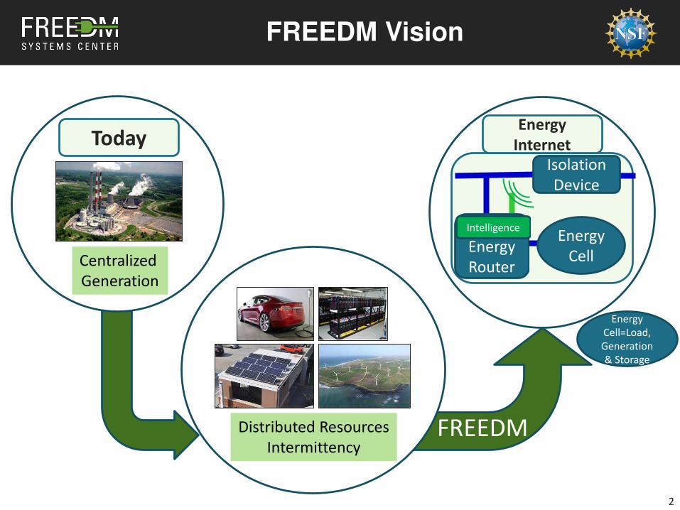
Low-Cost SST with LF Transformer for Power Distribution
Source: ABB Brochure of PCS100
AVC active voltage conditioner
Comparison LFT-SST solution and the conventional 50/60 Hz transformer Alternative candidate for future smart grid applications This SST do NOT process the full power flow, which results in significant cost saving vs. normal SST Combining controllability of SST and low cost of LF transformer
• Voltage scaling & galvanic isolation• Correction of voltage sags, unbalances
and phase angle errors
Alternative to MV SST Technology LFT with SST solution : AC-DC-AC low power SST + high power LF transformer
• Reactive power compensation• Can be extended to bidirectional
power flow control
Comparison with MV SST Technology (FREEDM System) Limited controllability of
the essential smart grid features
Bi-directional power flow
Do not enable DC distribution system
Space and weight penalty
Do not take advantage of the emerging WBG technologies

Strategic Research Plan
5

Gen-II Solid State Transformer
Specifications:• Input: 7.2kVac
• Output: 240Vac/120Vac; 400Vdc
• Power rating: 20kVA
Tested:• Input: 3.6kVac
• Output: 240Vac; 400Vdc
• Power rating: 10kVA
12

Gen III Solid State Transformer (Y7-Y8)
13
A more reliable and cost-effective Gen-III Solid State Transformer (SST) with improved energy
efficiency, power density, isolation capability, robustness and controllability
.
Major Accomplishments:
• HV/HF transformer with >20kV isolation capability (invention disclosure)
• World record 6kV-400V 10kW 40 kHz DC-DC converter based on LLC/DAB hybrid (APEC2015)
• Shoot through free AC-DC topology (APEC2016)
Major Challenges:
• Three stage power conversions as in Gen-I & II.
• MV rectifier stage hard switched & ultra high device turn-on stress
• Still large number of HV devices needed: Higher cost.
15" 18"
48
"
New Approach
Three stage power conversion

14
Three-Stage AC/AC & DC SST
J. E. Huber, D. Rothmund, L. Wang, and J. W. Kolar, “Full-ZVS modulation for all-SiC ISOP-type isolated front end (IFE) solid-state transformer,” in Proc. IEEE ECCE, Sep. 2016.
Key technologies Three-stage solution : multi-level resonant AC-DC with fixed gain+ boost dc-dc + LV inverter The simplest high-voltage-side topology and the simplest system-level control
LV
inverter
DC
AC
International Collaboration with FREEDM partners

2
Main breaker (MB)
p-ETO p-ETO
DiodeDiodeSilicon Carbide,
high voltage
Fast mechanical
switch (FMS)Auxiliary breaker
(AB)
Silicon, low
voltageMechanical,
high speed
MOV
TRV clamping,
energy absorving 15 kV, 200 A,
SiC p-ETO, bi-
directional
200 (400) A, MOSFET
Rds(on) < 1mOhm
Vbr = 100
200A, 15 kV
mechanical
disconnect switch
Open in < 1ms
Gen III Hybrid FID Development
15
• Hybrid FID designed combining a fast mechanical switch (FMS) in series with a low loss Si Mosfet with a parallel branch for the SiC ETO high voltage switch
• Low conduction losses by bypassing the semiconductors• HV SiC ETO device (> 13kV) lowers the on-state and switching losses• Only as fast as the mechanical switch• No arcing in the mechanical switch
t = tCS + tFMS + tMB + tMOV
t ≈ tFMS + tMOV
Hybrid CB V-I transientHybrid Fault Isolation Device

Distributed Energy Storage Devices
16
• DESD supports IEM and IPM functions by providing an energy buffer
with bi-directional power flow capability.
• Efficient converter interfaces between storage devices and FREEDM
DC and AC ports
• DESD Supports
– Renewable Integration
– Islanded Operation

DESD Standardization
• SiC Boost/Inverter power stage
• DESD Integration Platform
– Low-cost ARM for DESD-specific
Apps; DSP for power control
– MQTT Communication backbone
to SST
– CAN communication to battery
management system (BMU)
– MODBUS link between power
electronics controller and high-
level apps
17
SST
IEM, IPM Algorithms
MQTT
Vg
LgLf
CfCdc
CAN
ig
MODBUS
VV
ic
vcvdc

• High efficiency high power density
DC/DC Converter
• Integrates a 12V battery to 380V DC
• Stacks 1kW building blocks
• Uses GaN Devices on the high-voltage
side
18
Major AchievementsPower Electronics
C1
C2
Ls
T
C3
S4a C4
n:1:1
S4
ilVHV
+
-
C5
+
-
S3a
S3
VLV
n1
n2
n3
a
bd
e
c
iHVGaN
transistors
S2
S1
Converter prototype integrated with battery
Converter prototype efficiencySelected topology using GaN transistors
F. Xue, R. Yu, W. Yu and A. Q. Huang, "Distributed energy storage device based on a novel bidirectional Dc-Dc converter with
650V GaN transistors," 2015 IEEE 6th Int. Symp. on Power Electronics for Distributed Generation Systems (PEDG), 2015, pp. 1-6.
F. Xue, R. Yu, W. Yu and A. Q. Huang, "GaN transistor based Bi-directional DC-DC converter for stationary energy storage device
for 400V DC microgrid," DC Microgrids (ICDCM), 2015 IEEE First International Conference on, Atlanta, GA, 2015, pp. 153g-153l.
Fei Xue, R. Yu, W. Yu, A. Q. Huang and Yu Du, "A novel bi-directional DC-DC converter for distributed energy storage
device," 2015 IEEE Applied Power Electronics Conference and Exposition (APEC), Charlotte, NC, 2015, pp. 1126-1130.

• Gen II DC/AC converter with
reduced DC-bus Capacitor
– Interfaces 100Vdc energy storage
system to 120Vac output
– Two stage solution; very low current
ripple from storage system
– DC cap reduced 90% through control;
allows for the use of film capacitors
• System integrated with SST
inverter, showing a stable
interaction
19
10″
12″
3″
Major AchievementsPower Electronics
X. Liu and H. Li, "An Electrolytic-Capacitor-Free Single-Phase High-Power Fuel Cell Converter With Direct Double-Frequency
Ripple Current Control," in IEEE Transactions on Industry Applications, vol. 51, no. 1, pp. 297-308, Jan.-Feb. 2015.
Q. Ye and H. Li, "Stability analysis and improvement of solid state transformer (SST)-paralleled inverters system using
negative impedance feedback control," 2016 IEEE Applied Power Electronics Conference and Expo., 2016, pp. 2237-2244.
Q. Ye, R. Mo, Y. Shi and H. Li, "A unified Impedance-based Stability Criterion (UIBSC) for paralleled grid-tied inverters using
global minor loop gain (GMLG)," IEEE Energy Conversion Congress and Exposition, Montreal, QC, 2015, pp. 5816-5821.
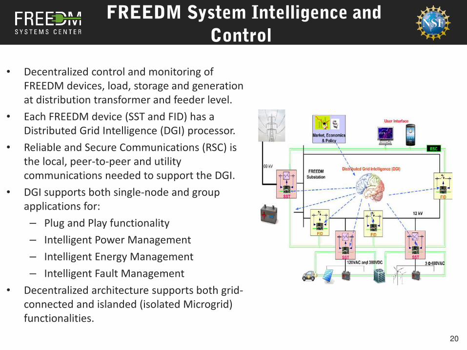
• Decentralized control and monitoring of
FREEDM devices, load, storage and generation
at distribution transformer and feeder level.
• Each FREEDM device (SST and FID) has a
Distributed Grid Intelligence (DGI) processor.
• Reliable and Secure Communications (RSC) is
the local, peer-to-peer and utility
communications needed to support the DGI.
• DGI supports both single-node and group
applications for:
– Plug and Play functionality
– Intelligent Power Management
– Intelligent Energy Management
– Intelligent Fault Management
• Decentralized architecture supports both grid-
connected and islanded (isolated Microgrid)
functionalities.
FREEDM System Intelligence and
Control
20

• Demonstration of FREEDM System functionalities including islanding, black start,
load control, frequency regulation in GEH
• GEH testbed enhanced with Distributed Grid Intelligence (DGI) software platform
for hosting applications and includes
– MQTT-based local device data transfer
– DNP3 protocol support for enterprise
SST(solid-state
transformer)
Wind
DRERDistributed
generation
DESDEnergy Storage
DGI
DCAC
DC
Load
Smart
House
AC
Load
HEMS
DESD
Energy
Storage
Utility
Source
Energy Cell 1.1 Energy Cell 1.2
GEH Medium-Voltage Loop
PV
DRERDistributed
Generation
SST
ARM BOARD
FREEDM NETWORK
HEMS
SCADA SYSTEM
Modbus
Mast
er
SS
TD
AT
A
DGI V2Modbus Slave
DSP
Measurements
Code
MQTT
ARM BOARD
MO
D
BU
S
Modbus Master
MQTT
FREEDM Device (DESD, DRER)
TCP/IP
DNP3
SCADA RT DATA
SCADA Application
Modbus Slave
DSP
Measurements
Code DEVICE DATA DGI
MQTT
Energy Cell
MO
D
BU
S
SST LAN
DNP3 Interface
Green Energy Hub Testbed
21

FREEDM Systems Controls
• FREEDM system is an engineered, non-linear, hybrid, multivariable
system having its challenges for identifying suitable analysis techniques
• FREEDM System Analysis:
– Comprehensive state space model development
– Equilibrium and feasibility Analysis
– System controller development and stability analysis
Grid
ZLine1
Z1
ZLine2
Z2
SST3
DC Load
Generation
Storage
AC Load
Generation
Storage
ZLine3
Z3
SST2
DC Load
Generation
Storage
AC Load
Generation
Storage
SST1
DC Load
Generation
Storage
AC Load
Generation
Storage
22

Technical Approach
Hierarchical Schematic of FREEDM System
Apply model reduction techniques to
reduce the complexity and order of the
model
Types of reduced analytical models:
− Large signal: State space models
− Small signal: Linearized models at
operation points
− Dynamic phasors: For analyzing large
systems with many power converters
Control Hierarchy:
• IEM provides the power reference
commands for IPM based on forecast data
and real time measurements
• IPM sets the current commands for each
FREEDM system based on IEM reference
signals
• Local controllers in each FREEDM system will
maintain the voltage and frequency at its
desired level
Intelligent Energy
Management (IEM)
Cost
Functions
SST system level
Feasibility constraints
Energy Cells
Forecast
Data
Intelligent Power Management (IPM)
Power LineSystem
Communication
Grid
SST3
DC Energy
Cells
AC Energy
Cells
SST2
DC Energy
Cells
AC Energy
Cells
SST1
DC Energy
Cells
AC Energy
Cells
Local Controller (LC)
, ∗ , ∗
∗,∗ ( = 1~3)
, ∗, ∗ ( = 1~3)
23

High Fidelity Model for Simulation
24
SST - Phase A
DC Load
Generation
Storage
AC Load
Generation
Storage
SST - Phase B
DC Load
Generation
Storage
AC Load
Generation
Storage
SST - Phase C
DC Load
Generation
Storage
AC Load
Generation
Storage
0.6+ j1.3 Ω/mile
0.6+ j1.3 Ω/mile
0.6+ j1.3 Ω/mile
1.0 + j1 Ω 1.0 + j1 Ω 1.0 + j1 Ω
7.2 KV (3 Ph)
400 V DC 400 V DC 400 V DC120 V AC 120 V AC 120 V AC
a
b
c
FREEDM System in LSSS Model

LSSS Model (Radial System)
25

Feasibility range can be increased by changing the rectifier output voltage .Droop control of rectifier output voltage reference
FREEDM System Equilibrium Analysis
= 8000 V
Due to the local
controller
= 6000 V = -200kW
min _ max _
Maximum of value is
specified by SST voltage
rating
Minimum of value is
specified by feasibility
analysis
26

LSSS model – Feasibility Analysis
27
• Feasibility analysis in LSSS model to transform infeasible SST into feasible one.
• Infeasibility is observed in node 40 of LSSS model and then, rectifier output voltage
reference is tuned to make it feasible.
• Voltage reference can be changed instantaneously for each individual SST from IPM
controller based on system status.
Infeasible system at node 40 @ P = 10 KW Feasible system at node 40 @ P = 10 KW

2 +-
Current PV Integrated Distribution System
1 12,
()
• = Controller (PR or PI)• = Delay due to sampling
and computation• = PW Modulator gain• Normalized by DC bus voltage
= 32 + + 2 + , − 2 + 132 + + 2 +
Only the front-end rectifier/inverter stage of SSTs are considered assuming that the DC link ensures decoupling with the later stages
28

Controller Stability 2 23 2 23 2 3
Thevenin
Equivalent = f(,2,3,,2,23)
, ,2 ,3
Feasibility: To ensure, + ∑=3 , = 0
Work done by SMC thrust.
• Feasibility of achieving target voltage magnitude
and frequency depends on the premise of local
controller stability and only when local controller, i.e. , is stable then tracking of , is ensured.
+-
• is no longer an independent disturbance, rather a function of . The
effective grid impedance that the converter sees looking into the point of common coupling, i.e. , plays a vital role in converter dynamics.
29

High Penetration of Power Electronic Converters2 23
2 3
= (,,,,,)
where (),(),() are all active, the interaction among which leads to extremely complex system dynamics
TheveninEquivalent
+-
High penetration Low penetration
= = Equivalent
transmission line impedance, i.e. passive components only - L, C, R
• Any system similar to FREEDM that includes heavy penetration of power electronic
converters, adds significant complexity to the design of local controllers.
• Significant research is being done on how to make local controllers less sensitive to
grid impedance variation.
30

Stability Analysis: Middlebrooks Criterion
31
• In 1976, Middlebrook introduced a stability criterion for cascaded DC systems [2].
• Middlebrook’s criterion has been extended to study stability of AC systems for
both 3 phase and single phase systems [3].
[1] R. D. Middlebrook, “Input filter considerations in design and application of switching regulators,” in Proc. IEEE Ind. Appl. Soc. Annu. Meeting,
1976, pp. 366–382.
[2]S. Lissandron, L. Dalla Santa, P. Mattavelli and B. Wen, "Experimental Validation for Impedance-Based Small-Signal Stability Analysis of Single-
Phase Interconnected Power Systems With Grid-Feeding Inverters", IEEE Journal of Emerging and Selected Topics in Power Electronics, vol. 4, no.
1, pp. 103-115, 2016.
System poles defined by: + =0

Impedance Based Controller Design: Global Minor Loop Gain Method
• Li et. al. from Florida State University developed an impedance based criterion for designing controllers for parallel inverters with knowledge of all inverter parameters.
• Impedance Based Controller Design: Global Minor Loop Gain Method
• Through detailed mathematical analysis they reach the total system stability criterion to be defined by the characteristic equation: + ∑= , =
• The same conclusion can be readily reached using Middlebrook’s criterion by combining all the equivalent current sources and equivalent admittances.
32[3] Q. Ye, R. Mo, Y. Shi and H. Li, "A unified Impedance-based Stability Criterion (UIBSC) for paralleled grid-tied inverters using global minor
loop gain (GMLG)", 2015 IEEE Energy Conversion Congress and Exposition (ECCE), 2015.
= , , = 0,

Smart Inverter Controllers
33
[4] R. Beres, X. Wang, F. Blaabjerg, M. Liserre and C. Bak, "Optimal Design of High-Order Passive-Damped Filters for Grid-Connected Applications", IEEE
Transactions on Power Electronics, vol. 31, no. 3, pp. 2083-2098, 2016.
[5] X. Wang, F. Blaabjerg and P. Loh, "Grid-Current-Feedback Active Damping for LCL Resonance in Grid-Connected Voltage-Source Converters", IEEE
Transactions on Power Electronics, vol. 31, no. 1, pp. 213-223, 2016.
[6] L. Zhou, W. Wu, Y. Chen, J. Guerrero, Z. Chen, A. Luo and X. Zhou, "Robust two degrees-of-freedom single-current control strategy for LCL-type grid-
connected DG system under grid-frequency fluctuation and grid-impedance variation", IET Power Electronics, 2016.
• Passive Damping: These techniques can reduce controller sensitivity to variation in grid
inductance at the cost of increased loss and lower attenuation at high frequency [4]
• Active Damping: These approaches provide resonance damping without reducing efficiency,
but suffers from lower damping performance in case of parameter variation. Also known as
virtual impedance methods [5]. The approaches have critical limits of grid impedance
variation, beyond which they fail.
Thevenin
Equivalent
+-
• Assuming (= ) to be predominantly
inductive, the worst case can be studied
considering no resistive damping in the
system. • , and (2+ ) constitute a 3rd order
system with a resonant frequency of ω =1+2+1 2+
• Even without variation in , this resonance
needs to be actively (or passively) damped to
achieve sufficient controller bandwidth.

Two Types of Instability
34
• Grid Impedance Variation:Only one rectifier is connected
at PCC along with PFC
capacitors. The single rectifier
can become unstable due to
variation of • Interaction between two
converters: For the same grid
impedance, interaction
between two converters may
cause instability
variation
may cause
instability
is
unchanged
[7]X. Wang, F. Blaabjerg, M. Liserre, Z. Chen, J. He and Y. Li, "An Active Damper for Stabilizing Power-Electronics-Based AC Systems",
IEEE Transactions on Power Electronics, vol. 29, no. 7, pp. 3318-3329, 2014.

Controller Challenges for FREEDM Architecture
35
• Impedance based controller design techniques are feasible for systems in
a closely contained systems with power electronic converters; however,
controller design must take into account the variation in .
• Reported works consider to be dominantly inductive contributed by
transmission lines and transformers. Therefore, by variation of grid side
inductor, the effect of grid impedance variation is emulated.
• In a FREEDM like architecture neighboring SSTs directly contribute to
actively shape the impedance that one SST sees looking into the point of
common coupling.
• For a SST based distribution system, the objective is to design local
controllers for readily deployable SSTs without retuning existing SSTs
• Design technique for local controllers that are less sensitive to grid
impedance, i.e. , variation needs to be developed.

Topics for this tutorial
36
Lecture L3
A. Traditional distribution systems, strengths, weaknesses
B. Overview of the FREEDM system and components
C.FREEDM system control and comparison with traditional
systems
D.Some features of the distribution system of the future:
pricing, cost / benefit, reliability