The forming characteristics of radial-forward extrusions Y.S. Lee, S.K. Hwang, Y.S. Chang, B.B....
17
The forming The forming characteristics of characteristics of radial-forward radial-forward extrusions extrusions Y.S. Lee, S.K. Hwang, Y.S. Chang, B.B. Hwang Y.S. Lee, S.K. Hwang, Y.S. Chang, B.B. Hwang Journal of Materials Processing technology, 15 June 2001 Presented by, Douglas Merrell September 15, 2004
-
date post
20-Dec-2015 -
Category
Documents
-
view
219 -
download
1
Transcript of The forming characteristics of radial-forward extrusions Y.S. Lee, S.K. Hwang, Y.S. Chang, B.B....

The forming The forming characteristics of radial-characteristics of radial-
forward extrusionsforward extrusionsY.S. Lee, S.K. Hwang, Y.S. Chang, B.B. HwangY.S. Lee, S.K. Hwang, Y.S. Chang, B.B. Hwang
Journal of Materials Processing technology, 15 June 2001
Presented by, Douglas Merrell
September 15, 2004

IntroductionIntroduction
The four basis types of extrusion are: The four basis types of extrusion are: direct (forward), indirect (backward), direct (forward), indirect (backward), hydrostatic, and impacthydrostatic, and impact
New types of extrusion are being New types of extrusion are being developed including radial extrusiondeveloped including radial extrusion

IntroductionIntroduction
In conventional extrusions material flows In conventional extrusions material flows parallel to the punch or dieparallel to the punch or die
In radial extrusions the materials flow In radial extrusions the materials flow perpendicular to the punch or dieperpendicular to the punch or die
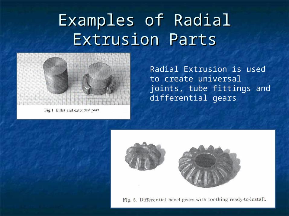
Examples of Radial Extrusion Examples of Radial Extrusion PartsParts
Radial Extrusion is used to create universal joints, tube fittings and differential gears

IntroductionIntroduction
The researchers developed a model The researchers developed a model using the rigid-finite element methodusing the rigid-finite element method
Using this model they were able to Using this model they were able to simulate changes in design simulate changes in design parametersparameters
Then they were able to determine Then they were able to determine the effect of certain parameters on the effect of certain parameters on the power requirementsthe power requirements

ReferencesReferences[1] S. Kalpakjian, Manufacturing Processes for Engineering Materials, 2[1] S. Kalpakjian, Manufacturing Processes for Engineering Materials, 2ndnd
Edition, Addison-Wesley, USA, 1991, p. 363.Edition, Addison-Wesley, USA, 1991, p. 363.[2] J. A. Pale, T. Altan, Development of equipment and capabilities for [2] J. A. Pale, T. Altan, Development of equipment and capabilities for
investigation of the multi-action forming of complex parts, Eng. Res. Center investigation of the multi-action forming of complex parts, Eng. Res. Center Net Shap Manuf. (1989) 8.Net Shap Manuf. (1989) 8.
[3] M. J. Saran, Journal of Materials Processing Technology. 27 (1991) 279.[3] M. J. Saran, Journal of Materials Processing Technology. 27 (1991) 279.[4] Air Force Materials Laboratory, Forging Equipment, Materials and Practices, [4] Air Force Materials Laboratory, Forging Equipment, Materials and Practices,
Metals and Ceramics Information Center, 1973. p. 164.Metals and Ceramics Information Center, 1973. p. 164.[5] E. Paul De Garmo, Materials and Processes in Manufacturing, Macmillan, [5] E. Paul De Garmo, Materials and Processes in Manufacturing, Macmillan,
New York, 1967, p. 27.New York, 1967, p. 27.[6] E. Paul De Garmo, Material Properties and Manufacturing Processes, [6] E. Paul De Garmo, Material Properties and Manufacturing Processes,
Malloy, Ann Arbor, MI, 1966, p. 31.Malloy, Ann Arbor, MI, 1966, p. 31.[7] J. Datsko, Material Properties and Manufacturing Processes, Malloy, Ann [7] J. Datsko, Material Properties and Manufacturing Processes, Malloy, Ann
Arbor, MI, 1966, p. 31.Arbor, MI, 1966, p. 31.[8] Metals Handbooks, The Materials Information Society, Vol. 2, 10[8] Metals Handbooks, The Materials Information Society, Vol. 2, 10thth Edition, Edition,
p. 104p. 104[9] S. Kobayahi, S.I. Oh, T. Altan, Metal Forming and the Finite Element [9] S. Kobayahi, S.I. Oh, T. Altan, Metal Forming and the Finite Element
Method, Oxford University Press, London, 1989, p. 30.Method, Oxford University Press, London, 1989, p. 30.[10] T. Huziyoshi, Die and Moulding, Daily Tech. Press, Tokyo, 1989, p. 446.[10] T. Huziyoshi, Die and Moulding, Daily Tech. Press, Tokyo, 1989, p. 446.[11] S. H. Lee, Forming characteristics of radial extrusion, Master Dissertation, [11] S. H. Lee, Forming characteristics of radial extrusion, Master Dissertation,
Inhan Graduate School, Inchon, 1999, p. 20.Inhan Graduate School, Inchon, 1999, p. 20.

Model PartModel Part
Billet diameter Billet heightPunch strokeMandrel diameterDie radiusDeflection radiusMandrel radiusGap height
16mm70mm40mm28mm2mm2mm2mm4mm
b = bottom thicknessd0= billet diameterdA= mandrel diameterh0= billet heighth1= workpiece heighthst= punch strokerA = die radiusru = deflection radiusrG = mandrel radiusSs = gap heightSR = annular gap widthSw = wall thickness

Material PropertiesMaterial Properties
Using AA 6063 Aluminum alloy Cold working (strain rate not a factor)
Calculated from σy, E, e, and Su

SimulationSimulation
Maximum pressure is 3257 MPa

SimulationSimulation
Verification that the model matches experimental testsAccurate to within 5%
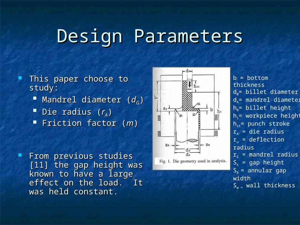
Design ParametersDesign Parameters
This paper choose to This paper choose to study:study: Mandrel diameter (Mandrel diameter (ddGG)) Die radius (Die radius (rrAA)) Friction factor (Friction factor (mm))
From previous studies [11] From previous studies [11] the gap height was known the gap height was known to have a large effect on to have a large effect on the load. It was held the load. It was held constant.constant.
b = bottom thicknessd0= billet diameterdA= mandrel diameterh0= billet heighth1= workpiece heighthst= punch strokerA = die radiusru = deflection radiusrG = mandrel radiusSs = gap heightSR = annular gap widthSw = wall thickness

Friction FactorFriction Factor
Friction has a large effect after 12.5 mm
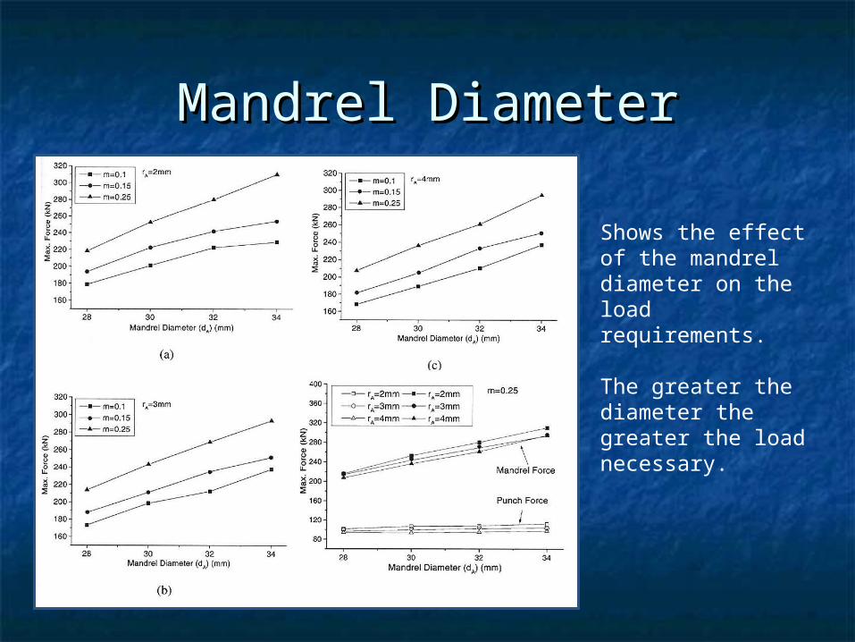
Mandrel DiameterMandrel Diameter
Shows the effect of the mandrel diameter on the load requirements.
The greater the diameter the greater the load necessary.

Die radiusDie radius
As the die radius gets larger the force requirements get smaller, but the die radius has the least effect of all the design parameters

ConclusionsConclusions
The friction factor has a large The friction factor has a large influence on the mandrel load but influence on the mandrel load but not on the punch load not on the punch load
The load increases with the mandrel The load increases with the mandrel diameter and the friction factordiameter and the friction factor
The load decreases slightly with an The load decreases slightly with an increase in the die radiusincrease in the die radius
ConclusionsConclusions
The mandrel diameter has the greatest The mandrel diameter has the greatest effect and the die radius has the leasteffect and the die radius has the least
Each of the design parameters had little Each of the design parameters had little effect on the punch loadeffect on the punch load
The punch and mandrel loads are The punch and mandrel loads are similar during the radial extrusion but similar during the radial extrusion but diverge at the start of forward extrusiondiverge at the start of forward extrusion

Questions?Questions?