THE FORMiNAO UCASFIED mmhmmmmmmiim EEEEEEEE
36
FUa STICTURE AM PRESSURE EFFECTS ON THE FORMiNAO SOOT PARTICLES IN. (U) PENNSYLVANIA STATE UNIV UNIVERSITY PARK DEPT OF MECHANICAL EN.. R J SANTORO UCASFIED i5 FEB 38 AFOSR-TR-88-8664 AFOSR-87-9145 F/G 21/2 U mmhmmmmmmiim EEEEEEEE EEEEE
Transcript of THE FORMiNAO UCASFIED mmhmmmmmmiim EEEEEEEE
FUa STICTURE AM PRESSURE EFFECTS ON THE FORMiNAOSOOT PARTICLES IN. (U) PENNSYLVANIA STATE UNIVUNIVERSITY PARK DEPT OF MECHANICAL EN.. R J SANTORO
UCASFIED i5 FEB 38 AFOSR-TR-88-8664 AFOSR-87-9145 F/G 21/2 U
mmhmmmmmmiimEEEEEEEEEEEEE
1925 J il J
~w w w w

* -d'' ,-tT
- ' 4 A''
)CUMENTATION PAGE ti)°- =:N.. 704-088
i A D5,01l). RESTRICTIVE MARKINGS
2A. SECURITY CLASSiFiCATION AUTHORITY 3. DISTRIBLTiONAVAILAILITY OF REPORT
. IApproved for public release;b. OECLASSIIC..ATONDOWNGRADI IEI ECTE distribution is unlimited.
.PERFORMING ORGANIZATION REP -NJ ) 5. MONITORING ORGANIZATION REPORT NUMBER(S)
ON& FOSR.Th. A~f~~i6. NAME OF PERFORMING ORGANID. 6o. OFFICE SY 7a. NAME OF MONITORING ORGANIZATION
The Pennsylvania State Universit D pial)AFOSR/NA
6c. ADDRESS (City, State, and ZIP Code) 7b. ADDRESS (City, State. and ZIP Code)
University Park, PA 16802 Building 410, Bolling AFB DC20332-6448
8a. NAME OF FUNDING/SPONSORING 8b. OFFiCE SYMBOL 9. PROCUREMENT INSTRUMENT IDENTIFICATION NUMBERORGANIZATION (If applicable)
AFOSR/NA I AFOSR-87-0145
8. ADDRESS (City, State, and ZIP Code) 10. SOURCE OF FUNDING NUMBERSBuldn 4 0, Boln AFB DC PROGRAM PROJECT TASK WORK UNITBuilding 410, Bo.ling AF ELEMENT NO. NO. NO ACCESSION NO.
20332-6448 61102F 2308 A2
t 1. TITLE (IncilUe Security Classfication)
(U) "Fuel Structure and Pressure Effects on the Formation of Soot Particles in Diffusion
Flames"12. PERSONAL AUTHOR(S)
Robert J. Santoro
13a l. TYPE OF REPORT 13b. TIME COVERED Iyj 14. DATE OF REPORT (Year, Month, Day) 15. PAGE COUNT
Annual FROM 1/15/87 TO I/3/.881 1988, February, 15 29
L 16. SUPPLEMENTARY NOTATION
17. COSATI CODES 18. SUBJECT TERMS (Continue on reverse if necessary and identify by block number)
FIELD GROUP SUB-GROUP
____________ Soot Formation,' Soot Particles-, Diffusion Flames ..
.1k,
19. ABSTRACT (Continue on reverse if necessary and identify by block number)
* -l During the first year of the present grant, efforts have concentrated on examining the effects offuel molecular structure on soot formation in diffusion flames. Studies involving alkane, alkene, alkyne
'-." and aromatic fuel species have been studied with specific attention given to the surface growth process.Analysis of these studies has demonstrated a strong fuel structure dependence for the amount of soot
formed, the conversion percentage of fuel carbon to soot, and the soot particle surface area present in
these diffusion flames. However, when surface area is taken into account, similar specific surface*growth rate coefficients are observed for all the fuels studied. These results point to a similar surface
2-7 growth process fo, all the fuels. Consistent with premixed flame results, the present studies show a
continual decrease in this specific surface growth rate coefficient with time. Other effects of fuelV,. structure observed include an acceleration of the inception of soot particles to lower locations and, thus,
earlier times in the flame as soot conversion percentage increases. These results also point to the.1, importance of the initia) particle inception process which appears to control subsequent soot particle
*. evolution.
20. DISTRIBUTION IAVAILABILITY OF ABSTRACT 21. ABSTRACT SECURITY CLASSIFICATION
MUNC-ASSIFED/JNLIMITED rZ SAME AS RPT U OT1C USERS Unclassified22a. NAME OF RESPONSIBLE INDIVIDUAL 22. rELEPO N$(rn(tuId Area COO) I 2ic.CFiC E, YB OL
Julia.. M Tishkoff A
' DO Form 1473, JUN 86 Previous ediions are ObSOlete. SECURITY CLASSIFICATCN OF 'W'AE
Unclassified• - ,% "',,- .. . ..'" " K " " *" '- * " " ' '

~ S 8 '-06d4
Annual Report
on
Fuel Structure and Pressure Effects on the Formationof Soot Particles in Diffusion Flames
(AFOSR Contract AFOSR-87-0145)
0
Prepared by
Robert J. SantoroDepartment of Mechanical Engineering
The Pennsylvania State UniversityUniversity Park, PA 16802
Submitted to:
Air Force Office of Scientific Research A.Cc .O_ _,_
Boiling Air Force Base NTIS C &Washington, D.C. D7 r C TA
February 1988 . . .... ..
fNSP0CTED 1----
00

- --- - - -
TABLE OF CONTENTS
Summary
1. INTRODUCTION .. ... ...... ....... ....... .......
2. RESEARCH OBJECTIVE .. .. .... ...... ....... ........
3. ACCOMPLISHMENTS AND STATUS OF WORK. .. .... ....... ..... 2
3.1 Atmospheric Diffusion Flame Facility .. .. ....... ...... ..... 3
3.2 High Pressure Diffusion Flame Facility .. ... ....... ......... 3
3.3 Laser Light Scattering Apparatus. .. .... ....... ....... ... 7
3.4 Atmospheric Ethene and Methane Flame Studies .. ... ....... ...... I
3.5 Fuel Addition Studies. .. ..... ...... ....... ........ 15
3.6 Fuel Molecular Structure Effects on Soot Surface Growth Processes .. .. ..... 20
3.7 Conclusions and Future Work .. .. ...... ....... ......... 24
4. REFERENCES. .. .... ....... ....... ....... ...... 27
5. PUBLICATIONS .. .. ...... ....... ....... ......... 28
6. MEETINGS AND PRESENTATIONS. .. ..... ....... ......... 28
7. PARTICIPATING PROFESSIONALS. .. ..... ...... ....... ... 28
8. INTERACTIONS .. .. ...... ....... ....... ......... 28
p %S i ti
(N0~g,& E

SUMMARY
During the first year of the present grant, efforts have concentrated on examining theeffects of fuel molecular structure on soot formation in diffusion flames. Studies involvingalkane, alkene, alkyne and aromatic fuel species have been studied with specific attentiongiven to the surface growth process. Analysis of these studies has demonstrated a strong fuelstructure dependence for the amount of soot formed, the conversion percentage of fuel carbonto soot, and the soot particle surface area present in these diffusion flames. However, whensurface area is taken into account, similar specific surface growth rate coefficients areobserved for all the fuels studied. These results point to a similar surface growth process forall the fuels. Consistent with premixed flame results, the present studies show a continualdecrease in this specific surface growth rate coefficient with time. Other effects of fuelstructure observed include an acceleration of the inception of soot particles to lower locationsand, thus, earlier times in the flame as soot conversion percentage increases. These resultsalso point to the importance of the initial particle inception process which appears to controlsubsequent soot particle evolution.
In addition to .these studies, significant progress has been made in the assembly andtesting of the experimental facilities used in these studies. Both atmospheric and highpressure diffusion flame facilities have been assembled along with the supporting laser lightscattering diagnostics. The atmospheric facility was utilized in the above experiments whilethe high pressure facility has recently been completed.

0I1. INTRODUCTION
Recent interest in the formation of soot in combustion processes has been motivated byseveral related developments. It is now well recognized that future combustion systems willoperate with broader specification fuels under conditions of higher operating pressures andstricter emissions standards. Each of these developments requires appropriate optimization ofcombustion processes and system performance capabilities; increase soot formation represents amajor challenge in this process. Since soot production has been shown to have strongsensitivity to fuel properties and operating conditions (temperature and pressure) [1,2], itwould be desirable to have an understanding of the fundamental processes governing sootformation and subsequent oxidation. However, such understanding must also be developedunder conditions which can be directly extended to processes occurring in practical combustionsystems. The objective of the present effort is to investigate the effects of fuel molecularstructure and operating pressure on the rates of soot formation, particle growth and burnoutin a well characterized flow field. These results are expected to provide an understanding ofthe fundamental processes involved in soot formation under conditions which are characteristicof practical combustion systems.
2. RESEARCH OBJECTIVE
0 The objective of the present study is to provide an understanding of the effects of fuelmolecular structure and operating pressure on the formation of soot particles in combustionsystems. These studies will be carried out in a series of laminar diffusion flames and requireextensive characterization of the particle, velocity and temperature fields present in theseflames. Studies will be conducted at both atmospheric and elevated pressures in order toe'xamine the effect of pressure on both the formation and oxidation of soot particles. Acoannular diffusion flame apparatus is used to study the soot formation processes in thesegaseous flames. The coannular burner has been selected as the experimental burner because ofits demonstrated capability to produce stable flames over a wide range of operating conditions[3,4,5]. Pressure is known to exert a significant effect on soot particle formation. Highpressure flame studies will be carried out in a flame facility assembled for this work whichhas the capability to operate at pressures as high as twenty atmospheres.
The effect of fuel structure is to be studied by the addition of aliphatic hydrocarbons(e.g., butane, butene, butadiene) and aromatics (e.g., alkylated benzenes, naphthalenes andnaphthenes) in various proportions to well characterized diffusion flames, Effects of suchcharacteristic compounds are examined using previously well characterized ethene and methanediffusion flames. These efforts can be supplemented with studies of prevaporized fuels (e.g.,pentane, decane) and include blends with characteristic aromatic species. The effect thattemperature has on soot formation and oxidation will also be investigated in these flames.Inert species (e.g., nitrogen and argon) can be added to either the fuel or oxidizer flow tovary the effective flame temperature. Previous studies using this approach have establishedthe strong sensitivity of soot particle formation and destruction processes to temperature [4,6].Using the measured particle volume fraction, size and number density, it will be possible toexamine the temperature dependence of the rates of initial formation, growth and subsequentoxidation of the soot particles.
The measurement approaches stress the use of non-intrusive optical diagnostic techniques.Laser viased techniques, such as laser light scattering and laser anemometry, are used tomeasure physical properties of the soot particles and to characterize the fluid velocity field.
0

At present, fine wire thermocouple measurements are used to determine the temperature field.As suitable non-intrusive techniques presently under development become available, they willbe applied to the present studies.
The essential thrust of this research effort is to obtain soot particle formation, growthand burnout rates using non-intrusive techniques so as to leave unaltered the dynamic couplingof the chemical and fluid mechanical processes. The operating conditions of the flamesstudied and fuels investigated are intended to be characteristic of the conditions to beencountered in future gas turbine systems. The consideration of gaseous and prevaporizedfuels avoids the complications that spray combustion diagnostics introduce to the study of sootformation, while preserving the consideration of realistic fuel constituents in the study. Suchstudies should complement work being undertaken to elucidate chemical precursor mechanismsas well as those concerned with more global measurements of soot production such as sootmass yield.
The detailed nature of the results of this study, as well as the tractable nature of theflame environment, will provide an important addition to the data base available forcombustion model validation. As an approach to this aspect of the problem, a concurrentmodeling effort will be undertaken to consider coupled fluid mechanic and chemical kineticrate processes important to soot particle formation and growth.. Our approach will be to useexisting models developed for conditions appropriate for laminar diffusion flames [7] and buildon their capabilities to include the important particle processes [8]. Particular attention willbe given to incorporating particle nucleation, surface growth, coagulation and oxidation.Efforts will also be made to collaborate with modeling approaches being attempted elsewhere[9]. Since the proposed experiments will consider a range of chemical structures undervarying pressure and temperature conditions, this work will offer an opportunity for modeldevelopment over a wide range of conditions.
3. ACCOMPLISHMENTS AND STATUS OF WORK
During the first year of the present grant, progress has been made in a number of areas.A brief summary of these accomplishments and current status of the present effort is givenbelow. This summary is followed by a more detailed presentation of the progress achieved todate.
Over the past year, our research efforts have concentrated on assembly of the requiredapparatus as well as initiation of the soot formation studies. The following tasks have beenaccomplished:
(1) The atmospheric diffusion flame facility has been completed and tested.
(2) The high pressure flame facility has been designed and constructed and is presently beingtested.
(3) The laser light scattering apparatus has been assembled and tested.
(4) A series of baseline studies have been completed for methane and ethene atmosphericdiffusion flames. The results of the ethene flames have been compared to previousstudies to assure that proper operation of the experimental facilities has been achieved.These flames have also been used as baseline comparison flames for a series of fueladdition studies.
2

(5) Fuel addition studies have been undertaken for methane, ethene, propene, butane, buteneand butadiene fuel species. These studies have been used to examine the degree ofconversion of fuel carbon to soot as a function of fuel flow rate and molecular structure.Additionally, comparisons between the methane and ethene baseline flames have provideda basis for examining potential synergism between the baseline fuel and the fuel speciesadded to the flame.
(6) Previously completed studies of ethene, propene, butenie and toluene fuel addition studieshave been further analyzed. Specific attention has been given to fuel structure effectson the surface growth process. These results indicate that the specific surface growthrate coefficients are similar in magnitude for all the fuels studied, even though theavailable surface area varies strongly with fuel species. The magnitude of the specificsurface growth rate coefficient is comparable to that observed in premixed flames.
In the sections which follow, these results will be discussed in detail. Based on this currentstatus, implications for future work will be examined.
3.1 Atmospheric Diffusion Flame Facility
The atmospheric diffusion flame facility was completed during the first quarter of theyear along with the basic laser light scattering apparatus. This facility is the majorexperimental apparatus used for the experiments conducted this year and a brief description ofthe burner facility follows.
The atmospheric diffusion flame facility consists of coannular diffusion flame burner,burner chimney, positioning system and gas metering system. The burner has a coannularconfiguration consisting of a 1.1 cm fuel tube surrounded by a 10 cm air annulus. The airpassage is partially filled with glass beads followed by a series of fine screens to provide flowconditioning. A ceramic honeycomb 2.54 cm in thickness is used at the exit to provide auniform flow field. The fuel tube which extends 4.8 mm above the ceramic honeycomb also ispartly filled with glass beads to condition the flow. The fuel flow can consist of up to threegases, each metered with a separate rotameter. This allows for mixtures of fuels as well asnitrogen dilution of the fuel for temperature control. These rotameters have been calibratedfor various gases using a soap bubble meter technique. The air flow is metered using a massflowmeter which can monitor flows up to 5 SCFM of air. To protect the flame from roomdisturbances, a metal chimney has been incorporated into the burner facility. This chimneytranslates horizontally with the burner while sliding vertically within the chimney. Slotsmachined in the chimney provide for optical access.
The burner is mounted on a pair of motorized translating stages which provide forvertical and horizontal motion. A manual translation stage is also included to allow foradjustment in the second horizontal direction and is used to align the burner with the laserscattering system. The motorized stages are used to traverse the burner through the laserbeam to obtain measurements over the cross section of the flame at a particular height in theflame. The motorized translation stages have a positioning resolution of 0.0127 mm which issufficient for the present experiments. Both motorized stages are interfaced to and controlledby an IBM-XT computer using the general purpose interface bus (GPIB-IEEE 488). Thesoftware to control the translation stages is incorporated into the data acquisition program forthe laser scattering measurements.
3.2 High Pressure Diffusion Flame Facility
In order to provide for studies at elevated pressure, a high pressure diffusion flamefacility has been designed and constructed. This facility is composed of a coannular burner,
3
C ,1 1 1 1 1
pressure vessel, positioning system and gas metering apparatus. The design chosen providesfor a significant degree of similarity between the atmospheric and high pressure diffusionflame burners. In the present system, a burner identical to that previously described insection 3.1 has been constructed. This burner is mounted inside a high pressure vesselcapable of withstanding the required operating pressures. Before describing this pressurevessel, the positioning system for the burner will be described.
Because of the mass of the pressure vessel, the approach chosen for the atmosphericsystem of vertically translating the entire burner and pressure vessel is not feasible. Ratherthe burner is mounted on a motorized translation stage located internal to the pressure vessel.Electrical connections are made through the base of the pressure vessel allowing externalcontrol of the burner's vertical position. To provide horizontal movement, the base of thepressure vessel is attached to a precision ball bearing stage which requires only a few poundsof force to move horizontally with weights as large as 1500 pounds attached. Thus, arelatively small motorized translation stage can be used to provide horizontal movement. Aswith the atmospheric burner, these motorized stages are capable of computer control using thelaboratory IBM-XT personal computer. The only disadvantage with its approach is thatsufficient space .must be provided within the pressure vessel to house the vertical motion
4assembly and the flexible gas supply lines for the burner.
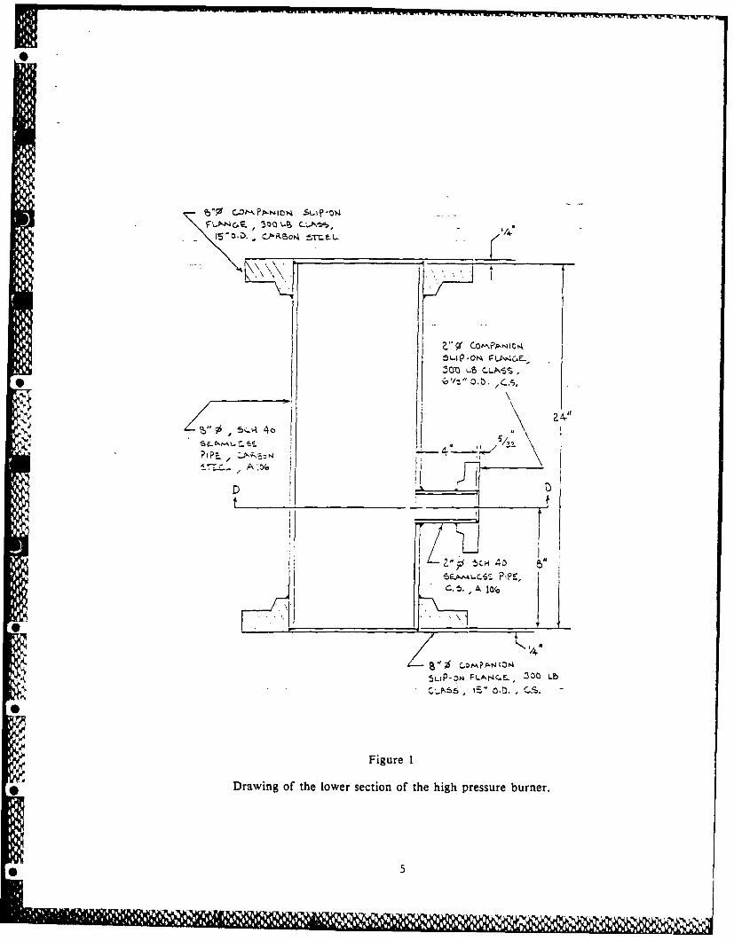
To accommodate this approach, the pressure vessel has been constructed as two separatesections. A drawing of the lower section is shown in figure 1. This section is constructed of8 inch diameter schedule 40 carbon steel seamless pipe which is 24 inches in length. A 2 inchdiameter schedule 40 carbon steel pipe is mounted and welded to this section to mount adiaphragm burst disc assembly. The burst disc is one of several safety features incorporatedinto the design of the burner. The vertical translating mechanism is mounted to the base ofthis lower section which is constructed of an 8 inch (300 lb class) blind flange. In additionto the electrical connection for the motorized translation stage, provisions for connection offuel and air lines are also made through this flange. Internal connections to the diffusionflame burner can be made with low pressure tygon tubing since no pressure difference existsacross the tubing wall inside the pressure vessel. With the upper section removed, access tothe burner is easily afforded.
The upper section of the pressure vessel is shown in figure 2. This section whichprovides for optical access to the flame region, is 30 inches in length and is constructed fromschedule XX 6 inch diameter carbon steel pipe. The wall thickness afforded by schedule XXpipe (0.864 inches) is required because of the four laige diameter windows mounted into thissection. These windows are two inches in diameter and 1/2 inch thick. These large diameterwindows allow sufficient optical access for both the laser light scattering and the laservelocimetry measurements. In addition to the windows, access has been provided to allowigniting the flame through a 1/2 inch NPT hole in the bottom of this section. Near the top,1/4 inch NPT holes are provided to monitor the temperature and pressure.
The operating pressure in the burner is adjusted presently using manual valves located inthe exhaust line of the burner. Connection to this exhaust system is made through a secondblind flange to which a 2 inch diameter exhaust line has been connected. Presentlyconsideration is being given to replacing this manual system with a back pressure regulatorwhich allows for better pressure control. At this time, no cooling is required for the burneror exhaust section. Temperature measurements indicate that for conditions typical for thepresent experiments, the burner does not heat up significantly.
Control and measurement of the fuel and air flow rates is accomplished using mass flowmeters and controllers. These meters are insensitive to the operating pressure and thus canbe calibrated at atmospheric pressure while providing accurate metering at elevated pressure.
4
SO I-
trZ.. A'.0
5L)PO F C. - IOL
5.5
dill Rmmm

Dip, t-, - -- a
77
66

The fuel metering system allows up to three gases to be mixed using independent mass flowcontrollers. These controllers maintain a constant mass flow independent of the pressure dropacross the meter. This assures a constant mass flow rate of fuel as well as a convenientstart-up capability. Otherwise, the fuel flow rate would decrease as the operating pressurewas increased, requiring continual readjustment. Because of the relatively large air flow raterequired, a mass controller approach is not feasible for the air metering. The air flow rate ismonitored by a mass flowmeter which will require adjustment as the operating pressure isvaried.
The high pressure burner facility has been statically tested to 400 psig. The presentlaboratory air supply facilities are capable of operation to 300 psig. The burner is presentlybeing tested under atmospheric conditions while final installation of the burner is beingcompleted. Figures 3 and 4 show recent photographs of the high pressure diffusion flameburner. The first experiments will involve high pressure flame studies using ethene andmethane as fuel. These studies will provide the baseline studies for the fuel addition studies,similar to the atmospheric studies described in sections 3.5 and 3.6.
3.3 Laser Light Scattering Apparatus
The laser light scattering apparatus, utilizing a 4W argon ion laser as the light source,*provides for particle extinction and scatterin- measurements. Scattering measurements are
presently made primarily at 90* although the system can be used to obtain measurements at45* and 135". The laser source is modulated using a mechanical chopper operating at I kHzto allow for synchronous detection of the transmitted and scattered light signals. Apolarization rotator is also incorporated in the system to allow adjustment of the polarizationof the incident light beam. The laser beam is focused in the burner using a 30 cm focallength lens which results in a probe beam diameter of 0.02 cm. Typically the laser isoperated at the 514.5 nm laser line with an output power of about 0.5W.
The transmitted light signal is detected using a silicon photodiode. The laser lightintensity is reduced by a neutral density filter (N.D. 2.0) to a level suitable for linear
*photodiode response. The scattered light is detected using a photomultiplier detector (PMT).The PMT has a narrowband filter center at 514.5 nm with a I nm bandwidth incorporated inthe PMT housing to help reject light other than that generated from the particle scatteringevent. A pinhole with a diameter of 1 mm located in front on this filter limits themeasurement volume length along the beam to 0.1 cm. The 15 cm focal length collection lensused to focus the scattered light onto the PMT, is arranged to provide unity magnification.Thus, the collection volume is a cylinder approximately 0.02 cmi in diameter and .1 cm inlength resulting in a volume of 3.1 x 10- 3 cm 3. The collection lens is preceded by apolarization filter to allow polarization discrimination for the scattered light detected. Thecollection solid angle is determined by a 1.27 cm aperture which is located between thepolarization filter and the collection lens. This aperture limits to the collection angle toapproximately 2*.
The output from each of the detectors is input into separate two phase lock-in amplifierswhich are interfaced to the IBM-XT computer over the GPIB bus. These units are capable offull computer control which allows for autoranging of the lock-in amplifiers. Computersoftware to control the lock-in amplifiers has been integrated with the stepper motor controlprograms to provide a complete data acquisition routine. These procedures provide a highdegree of user independent data acquisition.
Data taken from the lock-in amplifiers is stored on the IBM-XT internal disk. The lightscattering measurements require extensive data reduction to yield particle size information.Such calculations are performed more expeditiously on computers more capable than the
7
166

SS
aIL
i -
a''S
S-- Figure 3
Photograph of high pressure diffusion flame burner.
rN4,.
*2 5- . ..
'Ii
-,
4-. Figure 4
* Close-up view of high pressure diffusion flame burner.
laboratory computer used for the data acquisition. Thus, the IBM-XT is linked over theMechanical Engineering Department's network to the University's VAX computer facilities.This allows for rapid data analysis and graphical output. The necessary data reduction andplotting software have been developed for this facility. In addition, the latest version of theNASA Equilibrium code has also been implemented on the VAX computer. The equilibriumprogram is used to calculate the adiabatic flame temperature for the diffusion flame studies.
The scattered light detection system is calibrated to account for effects of the incidentlaser power, sample volume, light collection efficiency, photomultiplier sensitivity andelectronic gain of the system. The calibration is accomplished by passing ethene, a gas with aknown Rayleigh scattering cross section, through the fuel passage of the burner and measuringthe resulting scattered light. This procedure allows for an absolute determination of thedifferential scattering cross section per unit volume, Q(O), which is the power scattered in thedirection e per unit incident flux. For these calibrations the incident laser beam is verticallypolarized and 0 is usually 90*.
The laser light scattering and extinction apparatus provides the particle measurementcapability for the present studies. Analysis of the scattering measurements is based on a MIEtheory approach for spherical particles. For completeness, a brief review of the theoreticalbasis for this analysis is presented. The present data reduction programs mentioned earlier
* incorporate the approach described below to obtain particle size and concentration information.
In general, the interaction of a particle and light wave is dependent on:
1. index of refraction of the particle, m
2. particle size, D
3. particle number density, N
4. particle size distribution, P(D)
5. particle shape
6. wavelength of the scattered light
7. scattering geometry
* Obviously, measurement of any one of the above requires knowledge of all of the othervariables. In a typical combustion measurement of soot particles, only the scattering geometryand the wavelength of the light can be specified beforehand. The remaining unknowns aredetermined by an appropriate combination of measurements to reduce the number of freeparameters along with some reasonable assumptions. It is these assumptions which can resultin inaccuracies and therefore must be considered carefully.
Combinations of scattering measurements utilizing the angular and polarizationdependencies of the scattering process, or scattering and absorption measurements, have beenused to determine particle number density and size [3-51. In such an approach, the index ofrefraction is taken to be known, the particles are assumed to be spherical and a sizedistribution is assumed (e.g., log-normal).
The determination of particle size and number concentration from light scattering datadepends primarily on our capability to relate the measurement of scattered and absorbed lightintensity to the particle properties. Appropriate theories have been developed for spherical
- 9

particles and have been widely applied for aerosol measurements. The particle properties ofinterest are the differential scattering cross section, Cij (0), for production of scattered lightat a specified direction and total cross section for a specified particle size, Cext. Thesubscripts i and j for the scattering cross section assume letters v or h according to whetherthe state of polarization of the scattcred (i) and incident (j) radiation is perpendicular orparallel, respectively, to the plane of observation. For spherical particles of isotropicmaterial, only the case of i = j is of interest because cross polarization effects are absent.
The relationship between these cross sections and the experimentally measured quantitiesare expressed as
* fHDi s = IoNCii (0, ___ , m) G (1)
A
and
I L HMexp - f NCext lIm) ds (2)
10 0 A
where Is, I and 10 are the scattered, transmitted and incident intensities respectively, N isnumber concentration of particles, D is diameter, m is the refractive index, and G is aconstant which involves factors related to the sample volume and detection instrumentation.It should be noted that the scattering cross section measurements given by equation (1) arepoint measurements, while the extinction cross section is an integrated quantity over the pathlength L. Thus, to obtain local particle extinction values, a data inversion technique must beutilized [10].
In an experiment, the quantities which are determined, once appropriate calibrationfactors have been introduced, are
Qii - N Cii (3)
and
Kext w N C ext (4)
where Qii is the volumetric scattering cross section and Kext is the extinction coefficient.
Several approaches can be taken to determine the particle size from the above definedcross sections. Three are of interest with respect to the instrumental set up discussedpreviously. These are the ratio of scattering to extinction, Qvv(9 0*)/Kext, the ratios of thescattering signal at two angles (dissymmetry ratio) Qvv(4 5*)/Qvv(9 0*) and Qvv(45 *)/Qvv(13 5*),and the polarization ratio Qhh(90 *)/Qvv(90*); the scattering measurement angle is specified foreach quantity. Each of these ratios have a strong dependence on particle size and represent aredundant set of data in terms of the particle properties for particles in the Mie size region(D > A). For particles in the Rayleigh size region (D << A), scattering is isotropic so thedissymmetry ratio has a value of unity and the defined polarization ratio approaches zero.
10
**j)

0
Thus, in this small particle limit, only the scattering/extinction ratio yields size information.However, for soot formation processes, the rapid coagulation and surface growth processeslead quickly to particles in the Mie region. Nonetheless, the scattering measurementcapabilities described above, provide for the measurement of the particle size throughout theRayleigh and Mie regimes. Thus, processes from nucleation through particle growth andeventual particle oxidation are measurable.
With the particle size established, any one of the scattering cross sections can be usedto find N or fv, the soot volume fraction. The soot volume fraction, particle size and numberdensity are related by
= NirD 3 (5)
6
For a system in which simultaneous nucleation, particle growth and coagulation arepresent, a particle size distribution can be assumed to exist. In this case, the previouslydefined particle scattering cross sections must be averaged over the size distribution function,P(D), to yield mean values,
00 11
Cii (0) = f Cii (0, T___ , m) P(D) dD (6)o A,00
Cext (9) f Cext (0, _ D m) P(D) dD (7)o
A widely used expression for P(D) is the logarithmic normal distribution that is given by
P(D) . exp [- (In D/Dg) 2/2 ag21 (8)12fI agD
where Dg and ag are the geometric mean diameter and geometric mean standard deviation,respectively. As is discussed in Ref. 12, the introduction of particle size distribution affordsan opportunity to derive additional information by utilizing the previously redundantmeasurements of the scattering cross sections. These now afford the possibility of learning
* more about the nature of the size distribution function and agglomerate particle properties.
With the burner facilities and particle diagnostics completed, a series of soot formationstudies have been undertaken. The accomplishments and status of those experiments arediscussed in the next three sections.
* 3.4 Atmospheric Ethene and Methane Flame Studies
A series of ethene and methane flames have been studied to characterize their sootparticle fields. These experiments had two major objectives. The first was to allow acomparison between the present measurements and previous results for ethene/air diffusionflames 131. Such a comparison would assure that the atmospheric flame facility and laser lightscattering system were operating properly. The second objective was to provide a baselinedata set for these fuels to be used in the fuel addition studies.
l am
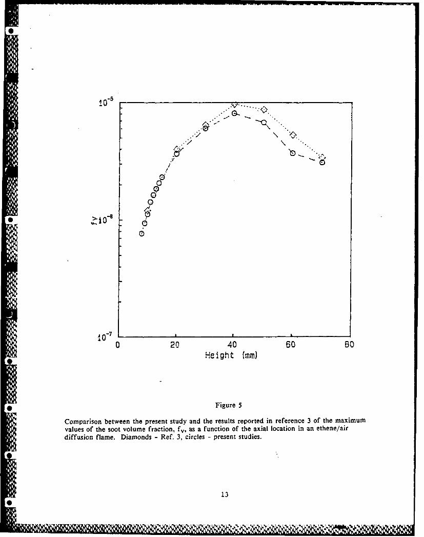
To validate the operation of the atmospheric burner facility and laser light scatteringsystem, a well characterized ethene/air diffusion flame was chosen foc study. The flameconditions correspond to an ethene fuel flow rate of 3.85 cm 3 /s and an air flow rate of 1.51SCFM (716 cm 3/s). Radial profiles of the light extinction and scattering by soot particles inthe flame were obtained at several axial locations. This data allow for the determination ofthe volume fraction, fv, the particle diameter, D63 , and the particle number concentration, N.Comparisons between this data and previously published results showed good agreement.Figure 5 shows a plot of the maximum value of fv as a function of the axial location in theflame compared to the results reported in Ref. 3. Some differences between the twoexperiments are observed in the region near the maximum fv in the flame (z = 40 mm) whichcontinue into the particle oxidation region. However, these differences are not consideredcritical at this time. Similar agreement has been observed for D63 and N.
The study of the effects of fuel molecular structure on the formation of soot is one ofthe major elements of the present work. However, a difficulty in studying fuel structureeffects has been the wide differences in the flame size and shape which results when variousfuels are burned at, for example, a characteristic condition such as the soot point. Thesedifferences result in important variations in the temperature and velocity fields which makequantitative comparisons impossible between the flames.
In the present studies, this difficulty is addressed by adopting a fuel addition approachinvolving well characterized baseline flames in which the soot particle field is characterized indetail. The fuel molecular structure effects are then investigated by adding an additional fuelcomponent to the baseline flame. However, the total carbon flow rate is kept constant. Thismeans that an appropriate fraction of the baseline fuel is replaced with the additive fuel.With the soot contribution from the baseline fuel known, the effect of the additive fuel onthe formation of soot particles can be determined. Under these conditions, the flame size andshape remains similar for all flames.
Two fuels, methane and ethene, have been selected to serve as the baseline flames. Themethane flames have relatively low soot particle formation and thus provide greater sensitivityfor measuring changes introduced by varying the fuel molecular structure. The ethene flamesrepresent the best studied set of diffusion flames presently available and provide a significantcomparative data base. Comparisons between the two baseline systems will also provide abasis for examining potential synergistic effects between the fuel addition species and thebaseline fuel. Four flames have been studied for the two fuels. The flow conditions for theflames are shown in Table 1. In order to illustrate the differences between the two baselineflames, a plot of the integrated soot volume fraction, Fv, is shown in figure 6 for three ofthe baseline flames. The value of Fv, which is a measure of the total amount of soot formedin the flame, is given by
RFv =
2 r f fvrdr (9)0
where R is the radius of soot particle field. Tn figure 6, Fv is plotted versus a non-dimensional height, j7, which is related to axial location z by
zD (10). where D is the diffusion coefficient of the fuel and V" is the volumetric flow rate of the fuel.
12
., l
iO-5 ., ..
00
-0
-
00
0 20 40 60 soHe ,Hight (ram)
•
Figure5
~Comparison between the present study and the results reported in reference 3 of the maximum
values of the soot volume fraction, fv, as a function of the axial location in an ethene/air
diffusion flame. Diamonds - Ref. 3, circles - present studies.
I13

1A0 -5
SI0_I
lm-
~10 -7>/
0
in/
j/
L
" .e ...... I .... .
. , 0 .005 .01 .005 .02 .025NON-DIMENSIONAL HEIGHT
Figure 6
* Comparisons of the integrated soot volume fraction, F., as a func: on of the non-dimensionalheiht Tianle -C 2H4 -3.85 cm/scile - 7.70 cm /s + C2H4 = 1.05 cm3/s;
squares - CH4 -9.8 cm 31s; diamonds -CH 4 -7.70 cm 3 /s.
* 14

Table I
Flow conditions for the baseline flame studies
Fuel Fuel Flow Rate Air Flow Rate(cm 3/s) (SCFM)
C2H4 3.85 1.5
C2H4 4.90 2.75
CH 4 7.7 2.75
CH 4 9.8 2.75
The significantly lower soot formation character of the methane flames as compared to theethene flame is clear. To illustrate the sensitivity of the methane baseline flame to theaddition of a different fuel species, the results of a flame burning a mixture of methane andethene is also shown in figure 6. The soot particle field measurements made for these
* baseline flames will be utilized in the fuel addition studies. The present status of thosestudies is discussed in the next section.
3.5 Fuel Addition Studies
With the baseline flame studies completed, the effects of fuel molecular structure on theshot formation process has been initiated. Experiments have emphasized the methane baselineflames to date. Table 2 summarizes the flame conditions which have been studied. Previously,results have been reported for various fuels added to an ethene diffusion [13] which serve asadditional data for the present studies. The experiments involving the fuel addition tomethane and ethene flames have been selected to examine three effects. Specifically, theexperiments are intended:
(1) To systematically examine the conversion of fuel carbon to soot as function of fuelflow rate. The experiments in which ethene or butene are added to the methaneflame address this point.
(2) To investigate the relative effects of changing the fuel structure in a series offuels which involve an alkane, alkene, and alkyne species. The experiments inwhich butane, butene and butadiene are added to the flame address this point.
(3) To compare the effects of the baseline fuel on the conversion of fuel carbon tosoot for the fuel addition approach. Experiments in which ethene and butene havebeen added to both baseline flames have been utilized for this comparison.
0
* 15

Table 2
Flow conditions for the fuel addition studies
Baseline Fuel Flow Rate Fuel Added Flow Rate Air Flow Rate(cm 3/s) (cm 3/s) SCFM
CH 4 8.75 C2H4 0.525 2.75
CH 4 7.7 C2H4 1.05 2.75
CH 4 5.6 C2H4 2.10 2.75
CH 4 5.6 C4 H8 1.05 2.75
CH4 5.6 C4 H8 0.872 2.75
CH 4 7.7 C4 H8 0.525 2.75
CH 4 5.6 C4HI0 1.05 2.75
* CH 4 5.6 C4 H6 1.05 2.75
The analysis which is presented below represents an initial approach to these studies. Itfocuses on the carbon conversion percentage for each of the flames based on the amount offuel added to the baseline flame. The contribution of the baseline flame is subtracted fromthe soot present in the flame based on the studies of the atmospheric ethene and methaneflames described in section 3.4. The carbon conversion percentage is calculated for the axiallocation displaying the maximum value of Fv, the integrated soot volume fraction. The carbonconversion percentage can be expressed as
% conversion= Is - me x 100= is- nB X 100 (II)hc - inB mi add
where mhs is the soot mass flow rate at the location of maximum Fv for the flame containingthe fuel addition, inc is the mass flow rate of carbon entering the burner, inB is the massflow rate of carbon contained as baseline fuel and fihadd is the mass flow rate of carboncorresponding to the fuel species added to the flame. The determination of the soot massflow rate at a particular height in the flame can be calculated from:
Rrns (zm) - 2ip ; v(r, Zm) fv(r, Zm) rdr (12)
0
where zm is the axial location where Fv is a maximum, p is the density of soot and v is thevelocity. Thus, the velocity profile must be known to precisely calculate the value of rffs .For the present analysis, the velocity has been assumed to be independent of r with a valuefor axial location zm taken from Ref. 14. This is a reasonable assumption for the locationsfor which Fv is observed to be a maximum (14]. With this assumption zis can be expressed as
* 16

ms (zm) - p v(zm) Fv(zm) (13)
where p is taken to be 1.8 gm/cm 3 . Tables 3-5 tabulate the results of this analysis forseveral of the flames studied. Included along with the percent conversion result is thecalculated adiabatic flame temperature for each flame. Each of the tables addresses one ofthe effects described at the beginning of this section.
Table 3
Flow conditions for the studies of the fuel flow rate effects
Baseline Fuel Flow Rate Fuel Added Flow Rate % Conversion* Tad(cm 3 /s) (cm 3 /s) (K)
CH 4 8.75 C 2 H4 0.525 21.5 2239
CH 4 7.70 C 2 H4 1.05 19.0 2252
- CH 4 5.60 C2 H4 2.10 16.2 2280
CH 4 7.70 C4 H8 0.525 36.6 2242
N CH 4 5.60 C2 H8 0.872 33.3
CH 4 5.60 C4 H6 1.05 35.1 2260
* p = 1.8 gm/cm3
In the fuel addition approach, a fraction of the baseline is replaced with the fuel speciesof interest subject to the constraint that the total flow rate of carbon into the flame ismaintained constant. It is of interest to ascertain if the percentage of fuel carbon convertedto soot is dependent on the amount of the baseline fuel replaced. The results tabulated inTable 3 for a methane baseline flame in which ethene or butene were introduced provideinformation on this point. For the ethene fuel addition case, the ethene flow rate was variedby a factor 4, whereas for the butene case the flow rate was changed by a factor of 2. Inthe case of the butene studies, the percent conversion remained relatively constant. For theethene case, a small systematic decrease in the conversion percentage of fuel carbon to sootis observed with increasing ethene flow rate. Consideration of the variation in the calculatedadiabatic flame temperature (Tad) does not explain the observed results since a decrease inthe conversion percentage is opposite to the current view of the effect of temperature onsoot production. It is conceivable that the observed variation in the conversion percentage iswithin the experimental error. A careful consideration of potential sources of error will becarried out to better resolve this question. At present, the data supports the conclusion thatthe conversion percentage is only weakly dependent on the fuel addition flow rate. Thedifferences observed between species with different fuel molecular structure is significantlygreater than the observed variations with
17

Table 4Flow conditions for the butane, butene, and butadiene addition studies
Baseline Fuel Flow Rate Fuel Added Flow Rate % Conversion* Tad(cm 3/s) (cm 3/s) (K)
CH4 5.6 C4HI 1.05 12.2 2243
CH 4 5.6 C4H8 1.05 35.1 2259
CH 4 5.6 C4H6 1.05 44.4 2285
p = 1.8 gm/cm 3
respect to flow rate. This provides an experimental justification to extend the results ofthese studies to more general fuel mixture conditions.
To specifically examine the effect of fuel molecular structure on the soot formationprocess, a series of flames are being examined involving C4 species. The flames studied
hinvolved additions of butane, 1-butene and 1,3-butadiene to a methane baseline flame. In thisseries the fuel structure is varied in terms of the arrangement of carbon bonds (single bondsand double bonds) resulting, of course, in a variation of the carbon to hydrogen ratio. Table4 tabulates the results of these experiments in terms of conversion percentage of fuel carbonto soot. Figure 7 shows the integrated soot volume fraction, Fv , as a function of the axialcoordinate, z. These results represent the most recent work undertaken and, thus, the presentanalysis is preliminary in nature.
Clearly, the results in Table 4 and figure 7 indicate a strong fuel structure effect withthe conversion percentage more than tripling. In addition, there is a systematic decrease inthe axial position where soot is first observed as the more sooty fuels are considered. Thisindicates that the reactions leading to the first soot particles occur more rapidly in theseflames. More detailed comparisons utilizing the velocity and temperature fields should offerthe potential for comparing the overall chemical kinetic rate information for the governingpyrolysis or oxidative pyrolysis mechanisms which have been established for these fuels.These velocity and temperature measurements are planned during the next phase of theproject. Comparisons are also possible between the methane and ethene baseline flames toinvestigate the importance of the C/H ratio which will vary strongly between the two flamesystems. To date, the experiments undertaken have not attempted to control temperaturewhich has been shown to be an important parameter in the soot formation process [6]. Anadvantage of the fuel addition approach lies in the fact that changes in the flametemperatures between different flames are often small. However, there are cases where thetemperature variation is significant enough to be important. As stated above, these studieshave not yet been fully analyzed and some addition measurements are required before detailedmechanistic information will be forthcoming. However, the present results do demonstrate thefuel addition approach does allow investigation of fuel molecular effects under comparableflame conditions. This data provides unique information on the fundamental mechanisms whichcontrol the formation of soot particles in flames.
The discussion above has focused on the effects of fuel molecular structure and flow rate.An additional important consideration is the importance of the baseline fuel which is used. Toexamine this point, two fuel addition studies involving ethene and butene were compared in
18

br-
C 4H6
t A C4H8
i [o C4HiO
S,, . - .
< rw / ,
3 -.-a10a Z / ,,
o L
o 7,
I-4 i- ./#
j
I
~- ; .
0
1 0 "-7 i _ ...1
0 20 40 60 80 ±00 120 140HEIGHT (mm)
Figure 7
Comparison of the integrated soot volume fraction, Fv, for the butane, l-butene and 1 3-butadiene fuel addition studies. The baseline flame had a methane 'flow rate of 5.6 cm-/s anda fuel addition flow rate of 1.05 cm 3/s.
19

which the baseline fuels were varied using methane and ethene. The results of these studiesin terms of conversion percentage are tabulated in Table 5.
Table 5Flow conditions for flame studies of baseline fuel synergism
Baseline Fuel Flow Rate Fuel Added Flow Rate % Conversion* Tad(cm 3/s) (cm 3/s) (K)
CH4 7.7 C2114 1.05 19.0 2252
CH4 7.7 C4H8 0.525 36.6 2242
C2 H4 3.85 C2H4 1.05 16.2 2369
C2H4 3.85 C4 H8 0.525 46.8 2359
*P= 1.8 gn/cm3
These results, as with the flow rate results previously discussed (see Table 3), do showsome sensitivity to a variation in the flame conditions. However, again, the differences aresignificantly smaller than the variation resulting from the fuel structure variation. For theexperiments shown in Table 5, the soot conversion percentage approximately doubles for thechange in fuel species. However, differences in the results for the various baseline flames fora particular fuel (ethene or butene) is typically 20-25%. It is also worth mentioning that thecalculated flame temperatures vary by about lOOK for the fuels studied. Thus, some of thevariation may be a result of the temperature difference. The comparison between the etheneand butene results may indicate different temperature sensitivities since the observed effectsof the baseline flame are reversed. This again points out the strength of the presentapproach to help isolate particular effects.
The above discussion has emphasized the conversion percentage of fuel carbon to sootparticles. This quantity is very useful in illustrating the impact of the effect of fuelmolecular structure on soot formation. However, it represents a global measurement of thesoot formation process. More fundamentally significant results are realized when the detailedtemperature time history characterizing these chenlically reacting systems are analyzed. Thismore fundamental analysis of the previously describe results is one of the objectives for thecurrent year of the program. In the next section more detailed results are presented for thesurface growth process. These results more fully represent the fundamental insights andquantitative information which is possible from studies of this nature.
3.6 Fuel Molecular Structure Effects on Soot Surface Growth Processes
The formation of soot particles is now viewed to undergo a common sequence of eventswhich govern the amount of soot formed and emitted from combustion systems. These include:(1) a chemical kinetically controlled reaction sequence which results in the formation ofprecursor species needed to form the first particles, (2) a particle inception stage whichresults in the formation of large numbers of small primary particles, (3) a particle growthperiod in which surface growth and particle coagulation processes contribute to the increase inparticle size and (4) a stage in which material is no longer added to the soot particles andsize is controlled by agglomeration or may even be reduced by oxidative attack. Recent work
20

in premixed flames has concentrated on more firmly establishing quantitative measurements ofthese processes. Significant progress has been made in understanding the surface growth andcoagulation processes which occur in premixed flames [15,161. Results of these and otherstudies have emphasized the importance of acetylene (C2H2) and the available surface area inthe particle surface growth process. However, to date, little information is available onsimilar processes in diffusion flames.
To help resolve this situation, the surface growth process for a number of fuel specieshas been studied using the fuel addition approach described above. These studies wereconducted using a well characterized ethene/air diffusion flame as the baseline flame.Different fuel species were added to the baseline fuel (ethene), such that the additionalcarbon flow rate is held constant. In addition, the flame size and shape remains similar forall the flames studied, thus minimizing changes in burner heat loss or particle transport in theflame. An ethene fuel flow rate of 3.85 cc/s (a carbon flow rate of 3.78x10 - 3 g/s) wasselected for the baseline flame since this diffusion flame has been extensively studied [4,14].A second fuel was added to the ethene flow to produce a total carbon flow rate of 4.81 x 10⁻³ g/s, an increase of 1.03x10- 3 g/s from the baseline case. Results obtained for ethene,propene, butene, and toluene will be discussed. In the case of toluene, the fuel was vaporizedusing a technique similar to that described by Gomez, et al. [17]. The flow rate conditions,soot conversion percentages and calculated adiabatic temperatures ate shown in Table 6.
Using the previously obtained detailed information on the particle paths for the etheneflame, comparisons between the different fuel mixtures can be made. For this comparison theregion of the flame containing the maximum soot volume fraction will be examined. Figure 8shows the time evolution of the soot volume fraction, fv, along the particle path whichtraverses the annular region of the flame where the maximum fv is observed. The fuelmixtures shown include three alkenes (ethene, propene and butene) and an aromatic (toluene)fuel. The calculated adiabatic flame temperatures for these fuel mixtures vary by less than10K. Thus, the temperature fields characterizing these flames should be similar allowing adirect comparison between the flames.
The soot volume fraction is observed to reach a maximum at a similar time (60 ms) foreach fuel mixture. For the alkene fuels, the observed residence time at which soot particlesare first observed and the value of fv at this time are very similar. However, the differentalkene fuels are observed to have measurably different rates of growth in terms of the changein fv with time. For the toluene mixture, although soot particles are first observed at .isimilar residence time (-21 ms), the initial concentration is much higher. This implies thatsoot particle inception occurred at an earlier time or that the inception process is much morevigorous. The particle size and number density measurements from nearby particle paths favoran interpretation indicating an earlier inception time. Thus, these results indicate that thespecific nature of the fuel species is observed to affect the initial particle formation processas well as the subsequent growth rates.
In order to examine the surface growth process in more detail, figure 9 shows theparticle surface area calculated from the particle diameter and number density measurementsfor the region along the same particle path. For each of the fuel mixtures studied thesurface area is observed to increase with time and fuel mixtures which exhibit larger soot
21

II
i I I I I I I I+
+
CC,
=3 C3H6/C2H4+ C2HtI
CD 10 -
10-7
40. 20. 40. 60. s0. 100.
TIME (MS)
Figure 8
Comparison of the soot volume fraction along the particle path exhibitingthe maximum soot volume fraction for fuel mixtures containing ethene,propene, butene, or toluene.
4 22

0 C2H'J S0 C2HA NS
YAC3H6
(.0X C7H8
/X/
'.4- A
U, A
/
20. 30. 40. 50. .. 60. 70. 80.
TIME (MS)
Figure 9
Soot particle surface area along the particle path exhibiting the maximumsoot volume fraction for fuel mixtures containing ethene (S - 4.9 cm 3/sand NS - 3.85 crn3/s fuel flowrate), propene, butene, and toluene.
* 23

Table 6
Baseline Fuel Flow Rate Fuel Added Flow Rate % Conversion* Tad
Flow conditions for fuel addition studies in ethene/air diffusion flames
C2 H 4 3.85 C 2 H4 1.05 16.2 2369
C 2 H4 3.85 C 3 H6 0.70 32.4 2368
C2 H4 3.85 C4 H 8 0.525 46.8 2359
C 2 H4 3.85 C7 H 8 0.30 88.2 2361
*P = 1.8 gm/cm 3
volume fractions also display greater surface area available for growth. Harris and co-workersin their studies of premixed ethene flames [15,161 have described the surface growth by
0 dM = k S [C2 H21 (14)
dt
where M is the mass of soot in g/cm3 , k is a growth rate constant (g/cm2 s atm), S is thesurface area (cm 2 ) and the last term is the concentration of acetylene latm]. In the presentexperiments, measurements of the acetylene concentration are not available. However acomparison of the specific surface growth rate (I/S dM/dt) can be obtained and is shown infigure 10. For these calculations, the density of soot was chosen to be 1.8 g/cm3 . Shownalso on this figure are the data for an ethene premixed flame studied by Harris, et al. with aC/O ratio of 0.94. The data of Harris et al. have been offset 15 ms to allow presentation ina proper time frame for these diffusion flame studies. The resulting specific surface growthrates calculated in this manner are very similar for each of the fuel mixtures studied asshown in figure 10. Furthermore, the comparison between the diffusion flame and premixedflame studies is quite reasonable. Considering the differences in the flame environments, thisagreement is very encouraging and indicates the surface growth processes in both flamesystems are quite similar. It is also of interest that for the propene, butene and toluenemixtures that slightly larger rate constants are observed at the earliest times. These resultsemphasize the need for further study of the particle inception process which may well becontrolling the evolution of the soot particle field.
3.7 Conclusions and Future Work
The results which have been presented above demonstrate the usefulness of the fueladdition studies of molecular structure effects. These experiments have provided quantitativeinformation on the conversion of fuel to soot particles for a variety of molecular structures.The conversion percentage has been shown to be only weakly dependent on the fuel flow rateor the baseline fuel to which the additions are made. Detailed studies of the surface growthprocess for soot particles in diffusion flames have revealed strong similarities for the fuelsstudied. This suggests a common mechanism for the surface growth process which provides asignificant reduction in the complexity in modeling soot formation. The present workrepresents the first detailed measurements providirg quantitative information on theseprocesses as a function of fuel structure.
24
0

00-
MHAR81S 0.950C2H4
U, XA C3H6-r + CqH8
X XC7H8zN +
S10 -4A
U-
ccA
C
CC U 0
U
LU
20. 30. 40. so. 60. 70. 80.
TIME (M51
Figure 10
40 Specific surface growth rate along the particle path exhibiting themaximum soot volume fraction. The dashed line (- )is a best fairedcurve through the ethene flame results.
25

0
Based on these results, future studies will concentrate on examining in a more detailedmanner the evolution of the soot particle field in diffusion flames. These studies will focuson the relationship between the known kinetic mechanisms for pyrolysis of these fuels and thesensitivity of the soot formation process to variations in the fuel molecular structure. Thiscomparison will require velocity and temperature measurements to complement the soot particlemeasurements. These measurements are among the objectives for the present year. As thesurface growth results indicate, the early particle formation region is critical to the evolutionof the soot particle field. Additional studies will emphasize measurements in this region as afunction of fuel molecular structure.
In addition to an interest in the atmospheric studies, the high pressure studies also pointto several interesting features. Since the observed conversion percentages of fuel carbon tosoot have shown strong fuel molecular structure sensitivity, one may similarly expectvariations in the pressure sensitivity as well. Since very little research has been directedtowards this topic, the present studies are an important step in providing a basis forunderstanding the effects of operating pressure on soot formation.
0
I
4. REFERENCES
1. Jackson, T. A., J. Energy, 6, p. 376 (1982).
2. Blazowski, W. S., Sarofim, A. F. and Keck, J. C., J. of Eng. Power, 103, p. 42 (1981).
3. Santoro, R. J., Semerjian, H. G. and Dobbins, R. A., Combustion and Flame, 51, p. 208(1983).
4. Sa;, toro, R. J., Semerjian, H. G., Twentieth Symposium (International) on Combustion, TheCombustion Institute, Pittsburgh, PA, pp. 997-1006 (1984).
5. Santoro, R. J., Yeh, T. T. and Semerjian, H. G., in Heat Transfer in Fire and CombustionSystems, edited by C. K. Law, Y. Jaluria, W. W. Yuen, K. Miyasaka, pp. 57-69, TheAmerican Society of Mechanical Engineers, New York (1985).
6. Glassman, I and Yaccarino, P., Eighteenth Symposium (International) on Combustion, TheCombustion Institute, Pittsburgh, p. 1175 (1981).
7. Mitchell, R. E., Sarofim, A. F. and Clomburg, L. A., Combustion and Flame, 37, p. 227OI (1980).
8. Dobbins, R. A. and Mulholland, G. W., Combust. Sci. and Tech., 40, p. 175 (1984).
9. Davis, R. and Baum, H., Center for Chemical Engineering, National Bureau of Standards(private communication).
10. Santoro, R. J., Semerjian, H. G., Emmerman, P. J., Goulard, R., !nt, J. Heat MassTransfer, 24, pp. 1139 (1981).
11. D'Alessio, A., DiLorenzo, A., Sarofim, A. F., Beretta, A., Masi, S., And Venitozzi, C.,Fifteenth Svmposium (International) on Combustion, The Combustion Institute, Pittsburgh,PA, p. 1427 (1975).
12. Dobbins, R. A., Santoro, R. J. and Semerjian, H. G., Ed. T. D. McCay and J. A. Roux,Progress in Astronautics and Aeronautics, Vol. 92, p. 208 (1984).
13. Santoro, R. J., "Fuel Molecular Structure Effects on Soot Particle Growth in DiffusionFlames," Twentieth Fall Technical Meeting of the Eastern Section of the CombustionInstitute, Gaithersburg, MD, Nov. 2-5, 1987.
14. Santoro, R. J., Yeh, T. T., Horvath, J. J. and Semerjian, H. G., Combustion Science andTechnology, 53, p. 89 (1987).
15. Harris, S. J. and Weiner, A. M., Combustion Science and Technology, 31, 155 (1983).
16. Harris, S. J. and Weiner, A. M., Combustion Science and Technology, 32, 267 (1983).
17. Gomez, A., Sidebotham, G. and Glassman, I., Combustion and Flame, 58, 45 (1984).
27
s_ -- ' " " " " ' ' ' "9U " " "

......~~ ------ --
0
5. PUBLICATIONS
1. Santoro, R. J., Yeh, T. T., Horvath, J. J. and Semerjian, H. G., "The Transport andGrowth of Soot Particles in Laminar Diffusion Flames", Combustion Science andTechnology, 53, 89 (1987).
2. Solomon, P. R., Best, P.E., Carangelo, R. M., Markham, J. R., Chien, P., Santoro, R. J.-. and Semerjian, H. G., "FT-IR Emission/Transmission Spectroscopy for In-Situ Combustion
Diagnostics", Twenty-first Symposium (International) on Combustion, in press.
3. Santoro, R. J. and Miller, J. H., "Soot Particle Formation in Laminar Diffusion Flames",Langmuir, 3, p. 244-254 (1987).
4. Santoro, R. J., Horvath, J. J. and Semerjian, H. G., "Surface Growth Processes for SootParticles in Diffusion Flames: Fuel Effects", to be submitted to Combustion and Flame.
6. MEETINGS AND PRESENTATIONS
1. "The Effect of Fuel Structure on the Formation and Growth of Soot Particles inDiffusion Flames", The Twenty-third Biennial Conference on Carbon, WorcesterPolytechnic Institute, July 19-24, 1987.
2. "Soot Particle Formation in Diffusion Flames", American Chemical Society Symposium onAdvances in Soot Chemistry, ASC Symposium, New Orleans, LA, August 30-September 4,1987.
3. "Fuel Molecular Structure Effects on Soot Particle Growth in Diffusion Flames",Twentieth Fall Technical Meeting of the Eastern Section of the Combustion Institute,Gaithersburg, MD, November 2-5, 1987.
4. "Optical Measurements of Soot Particles in Flames", Materials Research Society Symposia,Reno, Nevada, April 5-8, 1988.
A7. PARTICIPATING PROFESSIONALS
Dr. Robert J. Santoro, Associate Professor of Mechanical EngineeringMr. Douglas McKensie, Graduate Student, Department of Mechanical Engineering
. Mr. Jeff Leet, Graduate Student, Department of Mechanical Engineering
8. INTERACTIONS
* A number of researchers have directly used the extensive data set developed as part ofthis work to compare with or extend their own research. Some of those who have beendirectly provided data include:
Professor R. A. Dobbins, Brown University, Providence, RIDr. R. Hall, United Technologies Research Center, East Hartford, CTDr. R. Davis, The National Bureau of Standards, Gaithersburg, MDDr. P. Solomon, Advanced Fuel Research, Inc., East Hartford, CT
* 28
In addition to the interactions resulting from interest in the soot particle data, therehave been interactions with researchers on particle diagnostic problems. In some cases thishas resulted in direct visits to particular laboratories to assist in solving these problems.These interactions include:
Dr. M. Zachariah, The National Bureau of Standards, Gaithersburg, MDMs. Valerie Lyons, NASA Lewis Research Center, Cleveland, OH
Several other interactions have also occurred through a general interest in the worksupported by AFOSR with:
Columbian Chemical Company, Monroe, LACummins Engine Company, Columbus, IN
29
I[
29

77A
Al
'9;1
po