
The Focus Issue 71 October 30, 2009 A Publication for ... · PDF fileOctober 30, 2009 The...
11
October 30, 2009 The Focus Issue 71 www.padtinc.com 1 1-800-293-PADT October 30, 2009 A Publication for ANSYS Users Issue 71 By Eric Miller Most of the users out there have had R12 for some time now and hopefully you have had time to take a look at the changes in meshing. With all the other new paradigm changing features in this release, it is easy to pass over the changes in meshing, changes that we are finding have a very significant impact on the speed and quality of our models. In our opinion, the meshing capabilities in Workbench are a good example of the new thrust in the world of Workbench to walk a balance between automation/ease-of-use versus power/user-control. This is done in mesh- ing by keeping the pretty good default and high level control tools that have been there for a while and allowing the user to either set advanced global controls or attach detailed controls to specific objects. It is also a good example of how ANSYS, Inc. is merging different technologies and phys- ics to offer a single look and feel, while keeping physics specific settings. The first thing you will notice is going to be how the whole change in the project page makes meshing something that stands out more and a process step of its own. These changes also illustrate how meshing fits into the whole idea of combining physics and sharing things like meshes between systems. Once you use the new meshing tools you will very quickly notice the improvement in mesh quality. Most visible is the “clustering” seen in previous versions of the mesher , which is almost gone now. Figure 1 shows a good example of this. Not only does this provide a more uniform result distribution and eliminate spurious gradients, it also What’s New in Workbench Meshing? (Cont. on pg. 2) By Ted Harris Backyard swimming pools are very popular here in the Valley of the Sun. There's nothing like hopping into a 92 degree pool to cool you off on a 117 degree day. Really. It makes outside bearable during our 4 months of, "Yeah but it's a dry heat," to which I always add, "Like inside your oven." With a pool comes maintenance and repair, though, which bring us closer to the point of this article. A couple of years ago, I noticed a slow leak at the junction between my pool filter and the downstream piping. Being one of those engineers who loathes paying an expert to do some- thing I feel I can do myself, I endeav- ored to fix it. A couple of pool supply stores later I returned home with a $0.99 O ring. Two things about O rings: they don't work if they are too loose and they don't work if they are too tight. Unfortunately I missed the sweet spot and the fitting leaked when I got it all back together. In fact, I had tightened the threads on the fitting so much that the fitting itself was now cracked. I had also learned at the pool store that my installation was non-standard and they couldn't match the fitting to my particular filter. Time to call in an expert pool guy. Over $200.00 later I had a watertight connection again. In retrospect maybe the part was cracked to begin with, but if the O ring was indeed the problem in this case I gambled on a self repair and lost. Implementing Fluid Pressure Penetration In this Issue... 1.........What’s New in Workbench Meshing? 1.........Implementing Fluid Pressure Penetra- tion 5.........Announcing PADT’s first Web Based Class: Workbench Mechanical 6.........PeDAL: The APDL Editor 7.........Faster Fourier! Kill! Kill! (Nehelam Benchmarking Update) 8.........The Top 10 Most Important New Fea- tures in Workbench 12.0 (Cont. on pg. 4) Figure 1: Improvements in Surface Mesh Quality from R11 (Left) to R12 (Right) GoogleMaps view of the Neighborhood Just West of PADT. There are a Lot of Pools in Arizona!
Transcript of The Focus Issue 71 October 30, 2009 A Publication for ... · PDF fileOctober 30, 2009 The...
October 30, 2009 The Focus Issue 71
www.padtinc.com 1 1-800-293-PADT
October 30, 2009 A Publication for ANSYS Users Issue 71
By Eric MillerMost of the users out there have had R12 for some time now and hopefullyyou have had time to take a look at the changes in meshing. With all theother new paradigm changing features in this release, it is easy to pass overthe changes in meshing, changes that we are finding have a very significantimpact on the speed and quality of our models.
In our opinion, the meshing capabilities in Workbench are a good exampleof the new thrust in the world of Workbench to walk a balance betweenautomation/ease-of-use versus power/user-control. This is done in mesh-ing by keeping the pretty good default and high level control tools that havebeen there for a while and allowing the user to either set advanced globalcontrols or attach detailed controls to specific objects. It is also a goodexample of how ANSYS, Inc. is merging different technologies and phys-ics to offer a single look and feel, while keeping physics specific settings.
The first thing you will notice is going to be how the whole change in the project page makes meshing something that stands outmore and a process step of its own. These changes also illustrate how meshing fits into the whole idea of combining physics andsharing things like meshes between systems.
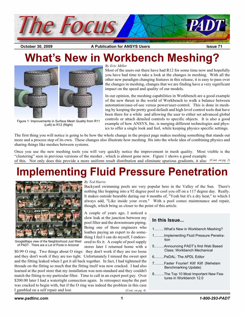
Once you use the new meshing tools you will very quickly notice the improvement in mesh quality. Most visible is the“clustering” seen in previous versions of the mesher , which is almost gone now. Figure 1 shows a good exampleof this. Not only does this provide a more uniform result distribution and eliminate spurious gradients, it also
What’s New in Workbench Meshing?
(Cont. on pg. 2)
By Ted HarrisBackyard swimming pools are very popular here in the Valley of the Sun. There'snothing like hopping into a 92 degree pool to cool you off on a 117 degree day. Really.It makes outside bearable during our 4 months of, "Yeah but it's a dry heat," to which Ialways add, "Like inside your oven." With a pool comes maintenance and repair,though, which bring us closer to the point of this article.
A couple of years ago, I noticed aslow leak at the junction between mypool filter and the downstream piping.Being one of those engineers wholoathes paying an expert to do some-thing I feel I can do myself, I endeav-ored to fix it. A couple of pool supplystores later I returned home with a
$0.99 O ring. Two things about O rings: they don't work if they are too looseand they don't work if they are too tight. Unfortunately I missed the sweet spotand the fitting leaked when I got it all back together. In fact, I had tightened thethreads on the fitting so much that the fitting itself was now cracked. I had alsolearned at the pool store that my installation was non-standard and they couldn'tmatch the fitting to my particular filter. Time to call in an expert pool guy. Over$200.00 later I had a watertight connection again. In retrospect maybe the partwas cracked to begin with, but if the O ring was indeed the problem in this caseI gambled on a self repair and lost.
Implementing Fluid Pressure Penetration
In this Issue...
1.........What’s New in Workbench Meshing?
1.........Implementing Fluid Pressure Penetra-tion
5.........Announcing PADT’s first Web BasedClass: Workbench Mechanical
6.........PeDAL: The APDL Editor
7.........Faster Fourier! Kill! Kill! (NehelamBenchmarking Update)
8.........The Top 10 Most Important New Fea-tures in Workbench 12.0
(Cont. on pg. 4)
Figure 1: Improvements in Surface Mesh Quality from R11(Left) to R12 (Right)
GoogleMaps view of the Neighborhood Just Westof PADT. There are a Lot of Pools in Arizona!

October 30, 2009 The Focus Issue 71
www.padtinc.com 2 1-800-293-PADT
generally results in fewer elements. This is the most obvious example of changesmade throughout the internal algorithms that generate meshes that provide moreuniform and “quality” meshes.
Most of the global controls are defined in the Details dialog for the Mesh branch ofthe tree, shown in Figure 2. The first option is the most important, Physics Preference.This determines what other options are available and sets the defaults for mostcommands for the type of problem you are trying to mesh. If you are doing CFD, youcan also specify if you are using CFX or FLUENT and the program sets defaultsappropriately. Most of Sizing options are the same as in earlier versions, with theexception of “Use Advanced Size Function.” Turning this to “On” exposes all thecool bells and whistles that make 12.0 a great release for meshing.
When you turn it on, you can tell the program to control the mesh based on proximityof features, the curvature of features or a combination of the two. You can also tell itto not use either, but allow you to set the advanced size options. Figures 3, 4 and 5show the results of each option and both together. As you can see it goes in and looksat the size of features and automatically introduces refinement as needed. We havebeen very happy with the curvature option for mechanical meshes.
This release also introduces a few new meshing methods. The most intriguing isMultizone. This is the first step towards automatic HEX meshing. It basically goesin and attempts to slices up your geometry to make six-sided volumes that can be hexmeshed. On some geometries it works pretty good, on others, not so good. Werecommend you play with it and get a feelfor how it works on your geometry. Figure6 shows a nice example.
The other method to be aware of is Non-Conforming, what we prefer to call patch-independent. This basically runs theTGRID mesher in batch mode which ig-nores the edges of surfaces and fills thevolume rather than meshing surfaces andgrowing a mesh inward as the patch depen-dent method does. Figure 7 is our silly testgeometry meshed with the two methods.We have found that large, complex geom-etries work very well with the patch inde-pendent method. We expect to see this getbetter with each release, especially forCFD applications.
If you work with shell or 2D geometry,you will also like the new inflation con-trols for shells. Figure 8 shows an exam-ple of how it puts nice, normal elementson edges. You can of course specifywhich edges and what ratios for the nor-mal layers. This is a much needed im-provement.
There are many other modifications de-serve their own articles, but we want tomake sure everyone is aware of them:
Inflation: CFD users live and die by theirboundary layer meshes and workbenchnow support better manual specification ofinflation layers as well as some pretty
(Meshing, Cont...)
(Cont. on pg. 3)
Figure 2: Mesh Details
Figure 3: Curvature Advanced Size Function
Figure 4: Proximity Advanced Size Function
Figure 5: Curvature & Proximity
Figure 6: Multizone Mesh
Figure 7: Conforming and Non-Conforming Meshes
Figure 8: Inflation on Shells
October 30, 2009 The Focus Issue 71
www.padtinc.com 3 1-800-293-PADT
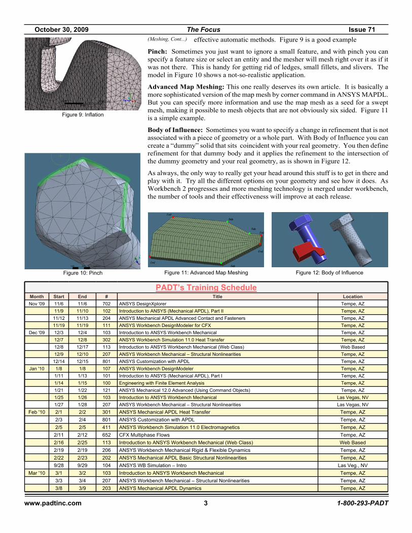
effective automatic methods. Figure 9 is a good example
Pinch: Sometimes you just want to ignore a small feature, and with pinch you canspecify a feature size or select an entity and the mesher will mesh right over it as if itwas not there. This is handy for getting rid of ledges, small fillets, and slivers. Themodel in Figure 10 shows a not-so-realistic application.
Advanced Map Meshing: This one really deserves its own article. It is basically amore sophisticated version of the map mesh by corner command in ANSYS MAPDL.But you can specify more information and use the map mesh as a seed for a sweptmesh, making it possible to mesh objects that are not obviously six sided. Figure 11is a simple example.
Body of Influence: Sometimes you want to specify a change in refinement that is notassociated with a piece of geometry or a whole part. With Body of Influence you cancreate a “dummy” solid that sits coincident with your real geometry. You then definerefinement for that dummy body and it applies the refinement to the intersection ofthe dummy geometry and your real geometry, as is shown in Figure 12.
As always, the only way to really get your head around this stuff is to get in there andplay with it. Try all the different options on your geometry and see how it does. AsWorkbench 2 progresses and more meshing technology is merged under workbench,the number of tools and their effectiveness will improve at each release.
Figure 9: Inflation
Figure 10: Pinch Figure 11: Advanced Map Meshing Figure 12: Body of Influence
PADT’s Training ScheduleMonth Start End # Title LocationNov '09 11/6 11/6 702 ANSYS DesignXplorer Tempe, AZ
11/9 11/10 102 Introduction to ANSYS (Mechanical APDL), Part II Tempe, AZ11/12 11/13 204 ANSYS Mechanical APDL Advanced Contact and Fasteners Tempe, AZ11/19 11/19 111 ANSYS Workbench DesignModeler for CFX Tempe, AZ
Dec '09 12/3 12/4 103 Introduction to ANSYS Workbench Mechanical Tempe, AZ12/7 12/8 302 ANSYS Workbench Simulation 11.0 Heat Transfer Tempe, AZ12/8 12/17 113 Introduction to ANSYS Workbench Mechanical (Web Class) Web Based12/9 12/10 207 ANSYS Workbench Mechanical – Structural Nonlinearities Tempe, AZ
12/14 12/15 801 ANSYS Customization with APDL Tempe, AZJan '10 1/8 1/8 107 ANSYS Workbench DesignModeler Tempe, AZ
1/11 1/13 101 Introduction to ANSYS (Mechanical APDL), Part I Tempe, AZ1/14 1/15 100 Engineering with Finite Element Analysis Tempe, AZ1/21 1/22 121 ANSYS Mechanical 12.0 Advanced (Using Command Objects) Tempe, AZ1/25 1/26 103 Introduction to ANSYS Workbench Mechanical Las Vegas, NV1/27 1/28 207 ANSYS Workbench Mechanical – Structural Nonlinearities Las Vegas, NV
Feb '10 2/1 2/2 301 ANSYS Mechanical APDL Heat Transfer Tempe, AZ2/3 2/4 801 ANSYS Customization with APDL Tempe, AZ2/5 2/5 411 ANSYS Workbench Simulation 11.0 Electromagnetics Tempe, AZ
2/11 2/12 652 CFX Multiphase Flows Tempe, AZ2/16 2/25 113 Introduction to ANSYS Workbench Mechanical (Web Class) Web Based2/19 2/19 206 ANSYS Workbench Mechanical Rigid & Flexible Dynamics Tempe, AZ2/22 2/23 202 ANSYS Mechanical APDL Basic Structural Nonlinearities Tempe, AZ9/28 9/29 104 ANSYS WB Simulation – Intro Las Veg., NV
Mar '10 3/1 3/2 103 Introduction to ANSYS Workbench Mechanical Tempe, AZ3/3 3/4 207 ANSYS Workbench Mechanical – Structural Nonlinearities Tempe, AZ3/8 3/9 203 ANSYS Mechanical APDL Dynamics Tempe, AZ
(Meshing, Cont...)
October 30, 2009 The Focus Issue 71
www.padtinc.com 4 1-800-293-PADT
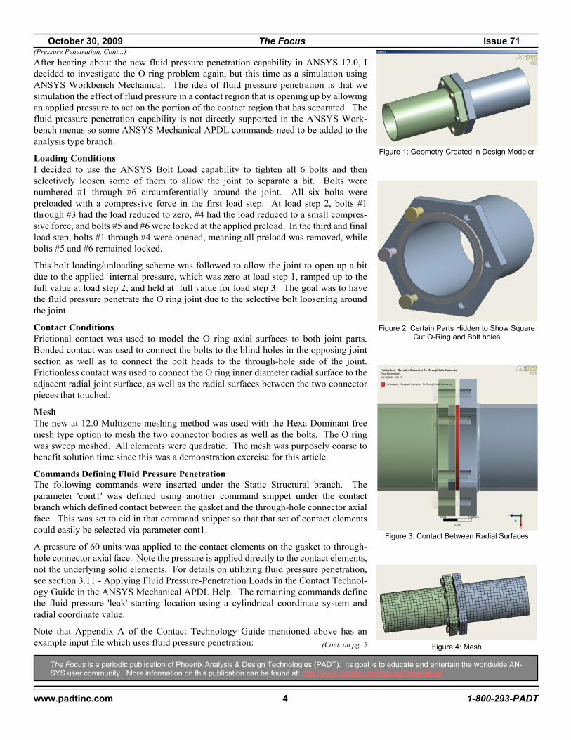
After hearing about the new fluid pressure penetration capability in ANSYS 12.0, Idecided to investigate the O ring problem again, but this time as a simulation usingANSYS Workbench Mechanical. The idea of fluid pressure penetration is that wesimulation the effect of fluid pressure in a contact region that is opening up by allowingan applied pressure to act on the portion of the contact region that has separated. Thefluid pressure penetration capability is not directly supported in the ANSYS Work-bench menus so some ANSYS Mechanical APDL commands need to be added to theanalysis type branch.
Loading ConditionsI decided to use the ANSYS Bolt Load capability to tighten all 6 bolts and thenselectively loosen some of them to allow the joint to separate a bit. Bolts werenumbered #1 through #6 circumferentially around the joint. All six bolts werepreloaded with a compressive force in the first load step. At load step 2, bolts #1through #3 had the load reduced to zero, #4 had the load reduced to a small compres-sive force, and bolts #5 and #6 were locked at the applied preload. In the third and finalload step, bolts #1 through #4 were opened, meaning all preload was removed, whilebolts #5 and #6 remained locked.
This bolt loading/unloading scheme was followed to allow the joint to open up a bitdue to the applied internal pressure, which was zero at load step 1, ramped up to thefull value at load step 2, and held at full value for load step 3. The goal was to havethe fluid pressure penetrate the O ring joint due to the selective bolt loosening aroundthe joint.
Contact ConditionsFrictional contact was used to model the O ring axial surfaces to both joint parts.Bonded contact was used to connect the bolts to the blind holes in the opposing jointsection as well as to connect the bolt heads to the through-hole side of the joint.Frictionless contact was used to connect the O ring inner diameter radial surface to theadjacent radial joint surface, as well as the radial surfaces between the two connectorpieces that touched.
MeshThe new at 12.0 Multizone meshing method was used with the Hexa Dominant freemesh type option to mesh the two connector bodies as well as the bolts. The O ringwas sweep meshed. All elements were quadratic. The mesh was purposely coarse tobenefit solution time since this was a demonstration exercise for this article.
Commands Defining Fluid Pressure PenetrationThe following commands were inserted under the Static Structural branch. Theparameter 'cont1' was defined using another command snippet under the contactbranch which defined contact between the gasket and the through-hole connector axialface. This was set to cid in that command snippet so that that set of contact elementscould easily be selected via parameter cont1.
A pressure of 60 units was applied to the contact elements on the gasket to through-hole connector axial face. Note the pressure is applied directly to the contact elements,not the underlying solid elements. For details on utilizing fluid pressure penetration,see section 3.11 - Applying Fluid Pressure-Penetration Loads in the Contact Technol-ogy Guide in the ANSYS Mechanical APDL Help. The remaining commands definethe fluid pressure 'leak' starting location using a cylindrical coordinate system andradial coordinate value.
Note that Appendix A of the Contact Technology Guide mentioned above has anexample input file which uses fluid pressure penetration:
The Focus is a periodic publication of Phoenix Analysis & Design Technologies (PADT). Its goal is to educate and entertain the worldwide AN-SYS user community. More information on this publication can be found at: http://www.padtinc.com/epubs/focus/about
(Pressure Penetration, Cont...)
Figure 2: Certain Parts Hidden to Show SquareCut O-Ring and Bolt holes
(Cont. on pg. 5
Figure 1: Geometry Created in Design Modeler
Figure 3: Contact Between Radial Surfaces
Figure 4: Mesh

October 30, 2009 The Focus Issue 71
www.padtinc.com 5 1-800-293-PADT
esel,r,type,,cont1sfe,all,1,pres,,60sfe,all,2,pres,,-1nslecsys,13 !cylindrical systemnsel,r,loc,1.7esln,esel,r,type,,cont1sfe,all,2,pres,,1 ! pressure leak start locationcsysallsel
SolutionSince this was a nonlinear analysis with large deflection effects and nonlinear contact, multiple substeps were used per load step.Note that in the final load step, the model converges for only a few substeps once the fluid has broken through. This is due to thefact that the O ring distorts quickly once contact is lost between the ring and the mating face of the connector. The goal of thissimulation was to model the fluid penetrating the contact region, not the post failure deflections of the O ring.
ResultsDeflection and contact status results were plotted in ANSYS Workbench. The fluid pressure penetration plots were created inMechanical APDL, although they could have been created in Workbench Mechanical by inserting the appropriate commands.
ConclusionsThe new fluid pressure penetration capability can be used to simulation fluid leaks in joints that separate. That separation requiresthat contact elements be used at the joint. As with most nonlinear analyses, care must be taken to avoid convergence difficulties.Further, although the technique is not yet directly supported in Workbench, the appropriate ANSYS commands can be added toenable the capability.
Now, about that hot water heater...
(Pressure Penetration, Cont...)
Figure 6: Contact Status for Progressive Pressure Penetration and JointSeparation
Figure 7: Contours of Fluid Pressure Penetration for Progressive JointSeparation
PADT Adds a new Workbench Mechanical Class and offers it On-LineFor some time now customers have asked for versions of our most popular classes to be given over the web. We are pleased toannounce Course 113 - Introduction to ANSYS Workbench Mechanical (Web Class). The class is presented in six 2.5 hour sessionsover a two week period and was developed from scratch by PADT’s technical staff based upon 15 years of experience teachingANSYS. Students will view the class over the Internet and listen on a conference call. The class does include workshops and studentswill be able to share their work over the web with the instructor or other students. This “virtual classroom” has been tested with afew test classes already and our team is ready to welcome people from around the world to any of the 5 scheduled dates or, if neededwe can set up a date that works for you. Learn more at: www.padtinc.com/support/training/course.asp?c=113
Figure 5: Total Deformation, Joint Seperating
October 30, 2009 The Focus Issue 71
www.padtinc.com 6 1-800-293-PADT
News - Links - Info· ANSYS once again makes more Small-Cap best-of lists, this time the Forbes 200 Best Small Companies <link> and
Deloitte’s Technology Fast 500 <link>
· ANSYS is used to simulate the Wimbledon Retractable Roof <link>
· Newest version of Ansoft’s HFSS is released with tons of enhancements <link>
· A couple of great issues of the ANSYS magazine have been published since the last The Focus <link>
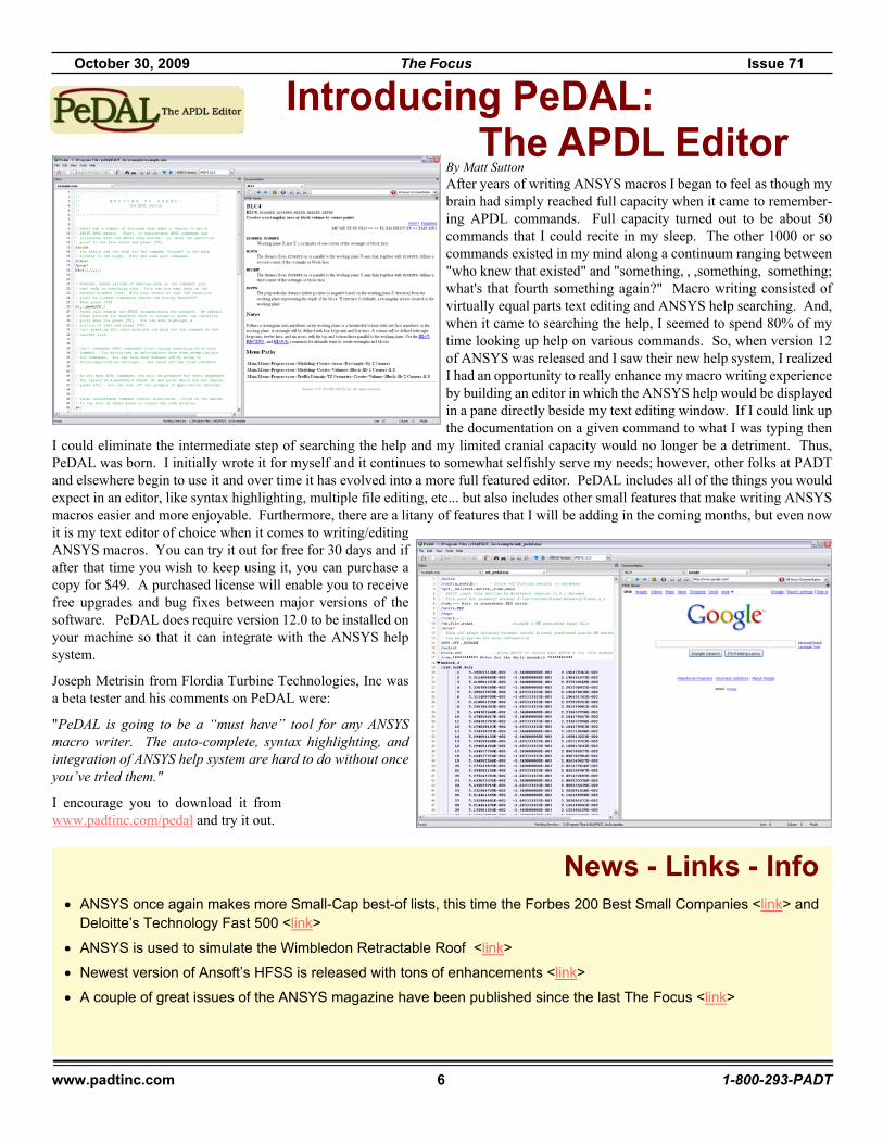
By Matt SuttonAfter years of writing ANSYS macros I began to feel as though mybrain had simply reached full capacity when it came to remember-ing APDL commands. Full capacity turned out to be about 50commands that I could recite in my sleep. The other 1000 or socommands existed in my mind along a continuum ranging between"who knew that existed" and "something, , ,something, something;what's that fourth something again?" Macro writing consisted ofvirtually equal parts text editing and ANSYS help searching. And,when it came to searching the help, I seemed to spend 80% of mytime looking up help on various commands. So, when version 12of ANSYS was released and I saw their new help system, I realizedI had an opportunity to really enhance my macro writing experienceby building an editor in which the ANSYS help would be displayedin a pane directly beside my text editing window. If I could link upthe documentation on a given command to what I was typing then
I could eliminate the intermediate step of searching the help and my limited cranial capacity would no longer be a detriment. Thus,PeDAL was born. I initially wrote it for myself and it continues to somewhat selfishly serve my needs; however, other folks at PADTand elsewhere begin to use it and over time it has evolved into a more full featured editor. PeDAL includes all of the things you wouldexpect in an editor, like syntax highlighting, multiple file editing, etc... but also includes other small features that make writing ANSYSmacros easier and more enjoyable. Furthermore, there are a litany of features that I will be adding in the coming months, but even nowit is my text editor of choice when it comes to writing/editingANSYS macros. You can try it out for free for 30 days and ifafter that time you wish to keep using it, you can purchase acopy for $49. A purchased license will enable you to receivefree upgrades and bug fixes between major versions of thesoftware. PeDAL does require version 12.0 to be installed onyour machine so that it can integrate with the ANSYS helpsystem.
Joseph Metrisin from Flordia Turbine Technologies, Inc wasa beta tester and his comments on PeDAL were:
"PeDAL is going to be a “must have” tool for any ANSYSmacro writer. The auto-complete, syntax highlighting, andintegration of ANSYS help system are hard to do without onceyou’ve tried them."
I encourage you to download it fromwww.padtinc.com/pedal and try it out.
Introducing PeDAL: The APDL Editor
October 30, 2009 The Focus Issue 71
www.padtinc.com 7 1-800-293-PADT
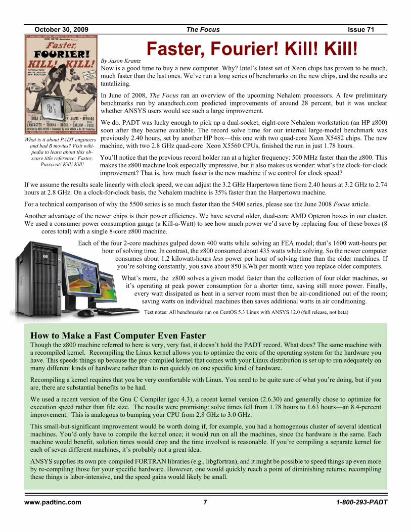
By Jason KrantzNow is a good time to buy a new computer. Why? Intel’s latest set of Xeon chips has proven to be much,much faster than the last ones. We’ve run a long series of benchmarks on the new chips, and the results aretantalizing.
In June of 2008, The Focus ran an overview of the upcoming Nehalem processors. A few preliminarybenchmarks run by anandtech.com predicted improvements of around 28 percent, but it was unclearwhether ANSYS users would see such a large improvement.
We do. PADT was lucky enough to pick up a dual-socket, eight-core Nehalem workstation (an HP z800)soon after they became available. The record solve time for our internal large-model benchmark waspreviously 2.40 hours, set by another HP box—this one with two quad-core Xeon X5482 chips. The newmachine, with two 2.8 GHz quad-core Xeon X5560 CPUs, finished the run in just 1.78 hours.
You’ll notice that the previous record holder ran at a higher frequency: 500 MHz faster than the z800. Thismakes the z800 machine look especially impressive, but it also makes us wonder: what’s the clock-for-clockimprovement? That is, how much faster is the new machine if we control for clock speed?
If we assume the results scale linearly with clock speed, we can adjust the 3.2 GHz Harpertown time from 2.40 hours at 3.2 GHz to 2.74hours at 2.8 GHz. On a clock-for-clock basis, the Nehalem machine is 35% faster than the Harpertown machine.
For a technical comparison of why the 5500 series is so much faster than the 5400 series, please see the June 2008 Focus article.
Another advantage of the newer chips is their power efficiency. We have several older, dual-core AMD Opteron boxes in our cluster.We used a consumer power consumption gauge (a Kill-a-Watt) to see how much power we’d save by replacing four of these boxes (8
cores total) with a single 8-core z800 machine.
Each of the four 2-core machines gulped down 400 watts while solving an FEA model; that’s 1600 watt-hours perhour of solving time. In contrast, the z800 consumed about 435 watts while solving. So the newer computer
consumes about 1.2 kilowatt-hours less power per hour of solving time than the older machines. Ifyou’re solving constantly, you save about 850 KWh per month when you replace older computers.
What’s more, the z800 solves a given model faster than the collection of four older machines, soit’s operating at peak power consumption for a shorter time, saving still more power. Finally,
every watt dissipated as heat in a server room must then be air-conditioned out of the room;saving watts on individual machines then saves additional watts in air conditioning.Test notes: All benchmarks run on CentOS 5.3 Linux with ANSYS 12.0 (full release, not beta)
Faster, Fourier! Kill! Kill!
What is it about PADT engineersand bad B movies? Visit wiki-pedia to learn about this ob-scure title reference: Faster,
Pussycat! Kill! Kill!
How to Make a Fast Computer Even FasterThough the z800 machine referred to here is very, very fast, it doesn’t hold the PADT record. What does? The same machine witha recompiled kernel. Recompiling the Linux kernel allows you to optimize the core of the operating system for the hardware youhave. This speeds things up because the pre-compiled kernel that comes with your Linux distribution is set up to run adequately onmany different kinds of hardware rather than to run quickly on one specific kind of hardware.
Recompiling a kernel requires that you be very comfortable with Linux. You need to be quite sure of what you’re doing, but if youare, there are substantial benefits to be had.
We used a recent version of the Gnu C Compiler (gcc 4.3), a recent kernel version (2.6.30) and generally chose to optimize forexecution speed rather than file size. The results were promising: solve times fell from 1.78 hours to 1.63 hours—an 8.4-percentimprovement. This is analogous to bumping your CPU from 2.8 GHz to 3.0 GHz.
This small-but-significant improvement would be worth doing if, for example, you had a homogenous cluster of several identicalmachines. You’d only have to compile the kernel once; it would run on all the machines, since the hardware is the same. Eachmachine would benefit, solution times would drop and the time involved is reasonable. If you’re compiling a separate kernel foreach of seven different machines, it’s probably not a great idea.
ANSYS supplies its own pre-compiled FORTRAN libraries (e.g., libgfortran), and it might be possible to speed things up even moreby re-compiling those for your specific hardware. However, one would quickly reach a point of diminishing returns; recompilingthese things is labor-intensive, and the speed gains would likely be small.
October 30, 2009 The Focus Issue 71
www.padtinc.com 8 1-800-293-PADT
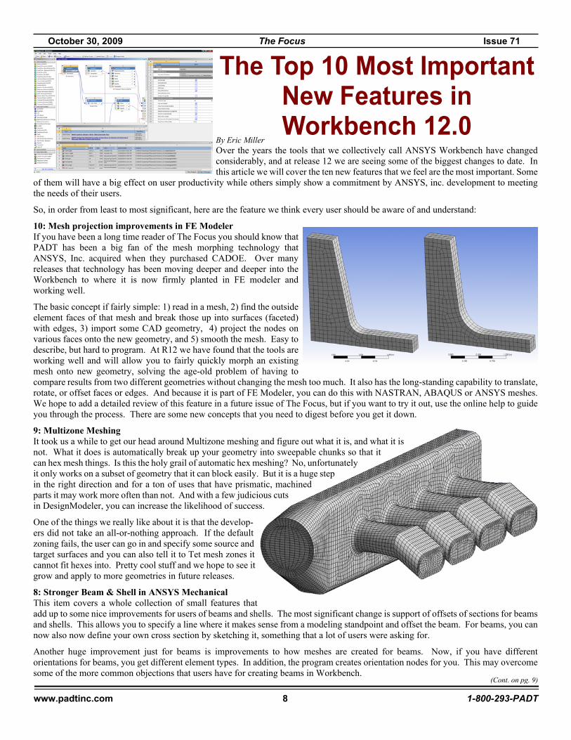
By Eric MillerOver the years the tools that we collectively call ANSYS Workbench have changedconsiderably, and at release 12 we are seeing some of the biggest changes to date. Inthis article we will cover the ten new features that we feel are the most important. Some
of them will have a big effect on user productivity while others simply show a commitment by ANSYS, inc. development to meetingthe needs of their users.
So, in order from least to most significant, here are the feature we think every user should be aware of and understand:
10: Mesh projection improvements in FE ModelerIf you have been a long time reader of The Focus you should know thatPADT has been a big fan of the mesh morphing technology thatANSYS, Inc. acquired when they purchased CADOE. Over manyreleases that technology has been moving deeper and deeper into theWorkbench to where it is now firmly planted in FE modeler andworking well.
The basic concept if fairly simple: 1) read in a mesh, 2) find the outsideelement faces of that mesh and break those up into surfaces (faceted)with edges, 3) import some CAD geometry, 4) project the nodes onvarious faces onto the new geometry, and 5) smooth the mesh. Easy todescribe, but hard to program. At R12 we have found that the tools areworking well and will allow you to fairly quickly morph an existingmesh onto new geometry, solving the age-old problem of having tocompare results from two different geometries without changing the mesh too much. It also has the long-standing capability to translate,rotate, or offset faces or edges. And because it is part of FE Modeler, you can do this with NASTRAN, ABAQUS or ANSYS meshes.We hope to add a detailed review of this feature in a future issue of The Focus, but if you want to try it out, use the online help to guideyou through the process. There are some new concepts that you need to digest before you get it down.
9: Multizone MeshingIt took us a while to get our head around Multizone meshing and figure out what it is, and what it isnot. What it does is automatically break up your geometry into sweepable chunks so that itcan hex mesh things. Is this the holy grail of automatic hex meshing? No, unfortunatelyit only works on a subset of geometry that it can block easily. But it is a huge stepin the right direction and for a ton of uses that have prismatic, machinedparts it may work more often than not. And with a few judicious cutsin DesignModeler, you can increase the likelihood of success.
One of the things we really like about it is that the develop-ers did not take an all-or-nothing approach. If the defaultzoning fails, the user can go in and specify some source andtarget surfaces and you can also tell it to Tet mesh zones itcannot fit hexes into. Pretty cool stuff and we hope to see itgrow and apply to more geometries in future releases.
8: Stronger Beam & Shell in ANSYS MechanicalThis item covers a whole collection of small features thatadd up to some nice improvements for users of beams and shells. The most significant change is support of offsets of sections for beamsand shells. This allows you to specify a line where it makes sense from a modeling standpoint and offset the beam. For beams, you cannow also now define your own cross section by sketching it, something that a lot of users were asking for.
Another huge improvement just for beams is improvements to how meshes are created for beams. Now, if you have differentorientations for beams, you get different element types. In addition, the program creates orientation nodes for you. This may overcomesome of the more common objections that users have for creating beams in Workbench.
The Top 10 Most ImportantNew Features inWorkbench 12.0
(Cont. on pg. 9)

October 30, 2009 The Focus Issue 71
www.padtinc.com 9 1-800-293-PADT
Post processing is now easier for beams with the new Beam Probe. This will give you detailed forces and moments onthe beam, especially useful if you are using a beam to connect geometry. The last significant change is the ability to fix rotation on beamand shell nodes based upon a user assigned coordinate system.
7: Remote PointIf you do a model in Mechanical APDL after workingin Workbench for a while, one o the features you missis the ability to define a remote load. This is a loadapplied to a point in space that is “tied” to a surface,edge or point on your geometry. As you can imagine,the APDL to do this can be pretty complicated. At R12this capability has been expanded to allow you to createremote points in space and then apply multiple forces orconstraints to that point. More importantly, you canattach a command snippet to the point and use the nodein an APDL macro. This gives the user considerablepower and flexibility to create a node in space and thenadd elements, loads, constraints or constraint equationsbeyond what Workbench currently supports.
Although this is not a very glamorous feature, it made our list because it is avery quick and simple way to include complex loads in your model without scripting or “fake” geometry. We recommend that the firstcouple of times you use it, you bring your model up in Mechanical APDL to study the way that the load or constraint is actually applied.
6: ANSYS Explicit STRThis is more than a new features, it is an entirely new solution option within Workbench. Explicit STR is a structural explicit dynamics
solver in workbench that uses the same look and feel as ANSYS Mechanical, but uses the AUTODYN solver instead ofthe Mechanical APDL solver. It is great for solving impact, drop shock, containment,
and large deformation problems that you would normally need LS-DYNA orAUTODYN to solve. But it has the advantage of workbench, includingbi-directional Associativity to CAD. It doesn’t support the FSI and explo-sions that full AUTODYN does, but for most explicit dynamics users, itdoes what they need. So far we are very impressed with how simple andpowerful this interface is, taking this area of simulation from the realm ofwizards to the preview of most ANSYS users.
5: User Defined Results/Full RST File Contents AvailableA big complaint that Workbench users have had for many releases is the fact that muchof the results that the ANSYS solver calculates were not available in Workbench. AtR12 users now have access to everything in the RST file through something calledUser Defined Results. This is a much simpler solution than the Etables andSMISC/NMISC long time APDL users are used to. The way it works is that you clickon the Solution branch on your model tree and then click on the Worksheet Tab. Thisbrings up a table of all the valid results in your result file. To plot those results, simplyright click on them and choose “Create User Defined Result.” You can then go backto your geometry tab and you’ll see the new result added to the tree.
An added feature is that you can also now do math on results values. If you look atthe table of results, there is a column labeled “Expression.” You can insert an emptyUser Defined Result and use the values in the Expression column as variables inequations.
4: Paths in Post ProcessingPath plots are another one of those obscure ANSYS Mechanical APDL features that you did notknow how much you used until you did not have it in Workbench. The developers at ANSYSlistened and added path plots at R12. The implementation is different in that it takes two steps. Inthe first you define your path and in the second, you insert a result object and scope that object toyour path.
You can create the path three different ways: 1) pick or specify two points in space, 2) use thex-Axis of a coordinate system, and 3) use an edge on your geometry. Once you have calculated the
(Cont. on pg. 10)
(WB Top 10, Cont...)

October 30, 2009 The Focus Issue 71
www.padtinc.com 10 1-800-293-PADT
results on the path you get a graph and a table, and the table can be exported to a text file.
3: Repair Tools in DesignModelerOne of the biggest time savers in R12 is looking to be the set of repair tools found inDesignModeler. DM has always had some tools that could be used to simplify and sometimesrepair bad geometry, but never the full suite of tools that users wanted. To begin with there aretwo “automatic” tools, the first being connect which closes small gaps and lines up vertices andedges, and the second which merges surfaces or edges that touch into a new single entity. Thefirst is great at repairing sloppy geometry and the second is useful in getting rid of small sliversor those annoying edges made up of tons of segments.
Beyond these global tools, there is a complete set of semi-automatic tools that allow the user toidentify entities that require repair based on the type of problem. They include repair for: edges,seams, holes, sharp angles, slivers, spikes and faces. Within each repair type, there are usuallyseveral methods that can also be chosen to fit the needs for your geometry. The help in this areais very good and we recommend that users read up on it so that they know what these powerfultools can do and when to use them.
2: WB2 InfrastructureMuch has been said and written about the Workbench 2 infrastructure. The sad part is that the huge amount of work done to create it ismostly not visible to the user. We can see the new project page or the interface on EngineeringData, but we can’t see how it quicklyallows CFX to calculate pressures for an ANSYS Mechanical run or how it extracts and manages parameter from 4 different pre- andpost-processors. And if you use your ANSYS, Inc. product the way you always have, you will see no advantage to WB2.
But if you find that you can do your simulation from within the WB2 environment, you will probably see some significant productivityimprovements. This is especially true if you build 3D parametric solid models and often repeat the same type of analysis over and overor if you are transferring loads between models. Although we grumbled a bit when we started, PADT’s engineers are finding value inthis infrastructure every day.
And this is just the beginning. WB2 will start todeliver scripting and journaling at 12.1 and growwith each release. We should also start to see morenative applications that are 100% WB2 that delivereven larger productivity gains.
1: Introduction of Project Schematic ConceptBy far the most important new feature in R12 ofWorkbench is the new concept of the Project Sche-matic. We covered this in detail in the last issue ofThe Focus <link> so there is not much to add hereother than to say that we really have grown to like itand it does make our simulations easier to under-stand, simpler to reuse and faster to iterate on. Thegraphical representation of sometimes complex anal-ysis processes really resonate with our engineeringbrains. It makes also makes it easy to go back to oldmodels and see what you did. We expect this way ofdoing things to be copied by ANSYS, Inc.’s compet-itors over the next couple of years.
Beyond the Top 10This article focuses on the 10 things introduced at R12 that PADT thinks are significant. But in reality they are just a few of manyimportant changes to the software that will change the way most analysts do their job. The gap between when this article was writtenand published has allowed PADT to use R12 even more, and as we do so we find more and more that it allows us to do things muchmore efficiently then we thought. And we are still learning
The most difficult part of taking advantage of these new capabilities, and we say this in every issue of The Focus, is stepping back anletting go of the old way of doing things. As a real world example, I was trying do demonstrate to someone how to do a typical turbineblade geometry optimization (hot-to-cold) in Workbench. I kept using complicated APDL commands imbedded in my tree andfollowing the same convoluted process I’ve used for over 20 years. Then I tried it again assuming I knew nothing - the result was thatI could set up the problem with a few input and output parameters and DesignXplorer. Nothing complicated, no imbedded commands.Just a few clicks.
So please, take a look at R12 and see what your top 10 features are. And if you can not find something you need, contact your supportprovider or talk to your co-workers. If you look at the problem differently, you may find what you want.
(WB Top 10, Cont...)

October 30, 2009 The Focus Issue 71
www.padtinc.com 11 1-800-293-PADT
In the past we have finished up The Focus with a page we called “Shameless Advertising...” The truth was that the page was reallyonly advertising PADT, and PADT related things. So, instead of doing advertising we thought we would just dedicate the final pageto explaining who PADT is, what we do and how we can hopefully help you. And, to make sure you read it, we will try and sticksomething funny in. Want to know more? Call Stephen Hendry at 207-333-8780 or e-mail [email protected].
Humor:How can you tell if your child is going to be an engineer? Watch for these tell-tale warning signs:
� You buy your child an educational software program, and she asks which authoring tool it was written in.� He has removed the voice box from his Talking Elmo doll and reprogrammed it to recite the periodic table.� He is picked last on every sports team.� He throws a temper tantrum every time you refuse to take him into Fry's Electronics� She has accepted a scholarship to MIT. And she's five.� He gets in fights in school because he owns a MAC and the other kids use a PC.� He/She can't get a date.� Forget Dr. Seuss and Beatrix Potter. She wants you to read her Hawkings.� When he is asked to play the Star of Bethlehem in the Christmas pageant, he asks, "Am I a white dwarf or red giant?"
What PADT Does
One of the reasons why PADT’s full name, Phoenix Analysis & Design Technologies, is so long is because our initial vision was toprovide a complete mechanical engineering solution. In fact, we almost called ourselves Phoenix Analysis, Design & ManufacturingTechnologies. But PADMT is even more annoying than PADT! We manage this diversity through three business units: CAE Sales& Services, Product Development, and Rapid Manufacturing.The CAE Sales & Services group is the group involved in all things ANSYS. Besides publishing The Focus, the CAE team doessales in Desert Southwest of ANSYS, Inc. and Stratasys products, Technical Support for our ANSYS customers, Training and a largeamount of consulting where we use ANSYS tools to solve simulation problems for our customers. This part of the company makesup half of our technical staff.The next group is Product Development. They do complete research, development, design and production of mechanical andelectro-mechanical systems. Most of our work in this are is focused on Medical Devices, Alternative Energy and Fuel Cells, andSemiconductor Manufacturing Equipment. With design engineers, laboratories and a stable of high quality vendors, our PD team iscapable of taking almost any idea from concept to product.The Rapid Manufacturing part of the company is the smallest, but the one with the mostcustomers. We have SLA, SLS and FDM systems in house as well as a full model shop with anNC lathe and mill. In addition, PADT can do prototype molding with soft tooling or rapidtooling. And when customers are ready for production we can server as their project coordina-tors to get injection molded parts made and assembled off shore.So, no matter what your needs, PADT can probably help with software, hardware, services ora reference to one of our partners. Learn more at www.PADTINC.com
PADT on the Web www.PADTINC.com PADT’s main website www.PADTMedical.com Medical device development www.DimensionSCA.com A machine that PADT makes www.uPrintStore.com A place to buy 3D Printers & Supplies www.XANSYS.org ANSYS User forum
Need ANSYS Help?PADT can help in many different ways, here are a few:
� We hold training here or at your facility <link>
� Leverage our APDL knowledge with the APDL Guide <link>
� Consider one-on-one support through mentoring, a greatway to get a quick start on something new <link>
� Attend a PADT Webinar <link>Join us on Facebook!
Search for PADT, Inc. And become a fan!


