the floating water bridge revised - University of Ljubljanapodgornik/download/clanek2.pdfFor...
5
The floating water bridge The floating water bridge Elmar C. Fuchs 1 , Jakob Woisetschläger 2 , Karl Gatterer 1 , Eugen Maier 1 , René Pecnik 2 , Gert Holler 3 and Helmut Eisenkölbl 1 J. Phys. D: Appl. Phys. 40 (2007) 6112-6114 1 Graz University of Technology, Institute of Physical and Theoretical Chemistry 2 Graz University of Technology, Institute for Thermal Turbomachinery and Machine Dynamics 3 Graz University of Technology, Institute of Electrical Measurement and Measurement Signal Processing ____________________________________________ Abstract When high voltage is applied to distilled water filled into two glass beakers which are in contact, a stable water connection forms spontaneously, giving the impression of a floating water bridge. A detailed experimental analysis reveals static and dynamic structures as well as heat and mass transfer through this bridge. 1. Introduction Water undoubtedly is the most important chemical substance in the world. Many attempts have been made to measure or calculate the structure of liquid water beyond the scale of the H 2 O molecule. This is a difficult task because of the hydrogen bonding network which itself is subject of various experimental and theoretical studies. It is being held responsible for many of water’s special properties and is also the reason why water must not be treated as a simple liquid [1,2]. The interaction of water with electric fields has been intensely explored over the last years, e.g. in context with electrospray-ionisation mass spectroscopy (ESI-MS) [3], but also unusual phenomena have recently been reported like, e.g., the electric field driven self-propulsion of a water droplet on a solid surface [4]. In this contribution we report another unusual effect of liquid water exposed to d. c. electric field: the floating water bridge. The first presentation of the water bridge was published by the ETH Zürich via the world wide web [5]. 2. Experimental Details The set-up consists of two beakers (100 mL) filled with triply deionized water. When exposed to a high d.c. voltage by putting electrodes into the beakers, water forms a stable, cylindrical bridge between two beakers. For the experiments presented herein the beakers were set on an even plane, one was fixed, the other movable and controlled by a step motor, and both beakers were separated by 1mm. The beakers were filled with triply deionized water (R=18 MΩ·cm) such that the water surface was about three millimeters below the beaker’s edge. Now one electrode was charged with 15 kV, the other was set to ground potential. A Phywe ”Hochsp.Netzger. 25kV” (Order No. 13671.93) or alternatively, a high-voltage generator using a LinFinity SG3524 pulse width modulator was used with a 24 nF ceramic capacitor set parallel to the electrodes. The voltage was measured by a potential divider of 500 MΩ / 500 kΩ to ground level. Since the voltage generators provide a limited current output, the electric current, which was measured with an oscilloscope, was stable at 0.5 mA. After a short electric discharge, which was building up between the two water surfaces, a water connection formed spontaneously between the two beakers, the water moved up the glass walls and built a water bridge. This effect is shown in Figs.1a-b. All experiments were performed under normal laboratory atmosphere using triply distilled water. High speed visualization was done using a color Kodak Motion Corder SR-Series 1000 (Eastman Kodak Company, San Diego, California), including a second on-board storage and a 8-48 mm zoom objective. For direct and indirect illumination two 24V/150W halogen lamps were used. For visualization of high frequency density oscillations inside the bridge a green Laser Pointer (Leadlight Technology Inc., Tao-Yuan, Taiwan, 5mW Series GLP-C0P1-05) was used.
-
Upload
phungquynh -
Category
Documents
-
view
219 -
download
4
Transcript of the floating water bridge revised - University of Ljubljanapodgornik/download/clanek2.pdfFor...
The floating water bridge
The floating water bridge Elmar C. Fuchs1, Jakob Woisetschläger2, Karl Gatterer1, Eugen Maier1, René Pecnik2, Gert Holler3 and Helmut Eisenkölbl1 J. Phys. D: Appl. Phys. 40 (2007) 6112-6114 1 Graz University of Technology, Institute of Physical and Theoretical Chemistry 2 Graz University of Technology, Institute for Thermal Turbomachinery and Machine Dynamics 3 Graz University of Technology, Institute of Electrical Measurement and Measurement Signal Processing
____________________________________________ Abstract When high voltage is applied to distilled water filled into two glass beakers which are in contact, a stable water connection forms spontaneously, giving the impression of a floating water bridge. A detailed experimental analysis reveals static and dynamic structures as well as heat and mass transfer through this bridge. 1. Introduction Water undoubtedly is the most important chemical substance in the world. Many attempts have been made to measure or calculate the structure of liquid water beyond the scale of the H2O molecule. This is a difficult task because of the hydrogen bonding network which itself is subject of various experimental and theoretical studies. It is being held responsible for many of water’s special properties and is also the reason why water must not be treated as a simple liquid [1,2]. The interaction of water with electric fields has been intensely explored over the last years, e.g. in context with electrospray-ionisation mass spectroscopy (ESI-MS) [3], but also unusual phenomena have recently been reported like, e.g., the electric field driven self-propulsion of a water droplet on a solid surface [4]. In this contribution we report another unusual effect of liquid water exposed to d. c. electric field: the floating water bridge. The first presentation of the water bridge was published by the ETH Zürich via the world wide web [5]. 2. Experimental Details The set-up consists of two beakers (100 mL) filled with triply deionized water. When exposed to a high d.c. voltage by putting electrodes into the beakers, water forms a stable, cylindrical bridge between two beakers. For the experiments presented herein the beakers were set on an even plane, one was fixed, the other movable and controlled by a step motor, and both beakers were separated by 1mm. The beakers were filled with triply deionized water (R=18 MΩ·cm) such that the water surface was about three millimeters below the beaker’s edge. Now one electrode was charged with 15 kV, the other was set to ground potential. A Phywe ”Hochsp.Netzger. 25kV” (Order No. 13671.93) or alternatively, a high-voltage generator using a LinFinity SG3524 pulse width modulator was used with a 24 nF ceramic capacitor set parallel to the electrodes. The voltage was measured by a potential divider of 500 MΩ / 500 kΩ to ground level. Since the voltage generators provide a limited current output, the electric current, which was measured with an oscilloscope, was stable at 0.5 mA. After a short electric discharge, which was building up between the two water surfaces, a water connection formed spontaneously between the two beakers, the water moved up the glass walls and built a water bridge. This effect is shown in Figs.1a-b. All experiments were performed under normal laboratory atmosphere using triply distilled water. High speed visualization was done using a color Kodak Motion Corder SR-Series 1000 (Eastman Kodak Company, San Diego, California), including a second on-board storage and a 8-48 mm zoom objective. For direct and indirect illumination two 24V/150W halogen lamps were used. For visualization of high frequency density oscillations inside the bridge a green Laser Pointer (Leadlight Technology Inc., Tao-Yuan, Taiwan, 5mW Series GLP-C0P1-05) was used.

The floating water bridge
To record the surface temperature along the water bridge, a Inframetrics Model 760 Infrared Thermal Imaging Radiometer (Inframetrics, North Billerica, Massachusetts) was used, including a 20 degree IR lens. Operated at a 50 Hz mode and in the 8-12 µm standard range, every 4 frames were averaged for the evaluation presented in figure 2. In order to calculate the water surface temperature from IR emission, an emissivity value of 0.96 was assumed for the distilled water. For Schlieren visualization a standard Schlieren set-up was used, including a 200 mW Argon-ion laser (ILT 5490, Ion Laser Technology, Salt Lake City, Utah) operated in multiline mode and a 20x microscope objective together with a 12.5 µm pinhole as light source. The optical path was formed by two folding mirrors (plane, λ/1 surface, 80 mm diameter) and two spherical mirrors (focal length 1524 mm, λ/1 surface, 150 mm diameter) in a symmetric optical arrangement, with a parallel beam in the test section. The recordings in figure 3 were done using no Schlieren stop, the Kodak Motion Corder described above, and an additional cylindrical lens (focal length 150 mm, 50 mm diameter) placed in the optical path right after the water bridge. This additional lens was used to compensate for the diffraction by the cylindrical geometry of the water bridge and enabled a visualization of inner structures deflecting light in lateral direction. 3. Results and Discussion Almost no electrolysis was observed and the bridge did not form, respectively, was destroyed when ions were added to the water or if water of higher conductivity was used. With glass beakers of 6 cm in diameter, the bridge had a cylindrical form with a diameter of 1 to 3 mm. If the movable beaker was pushed away from the fixed one, the bridge remained intact up to an extension of 25 mm if the voltage was raised to 25 kV (figure 1c).
Figure 1. Water bridge formation: (a) Rise of water in both beakers after a high voltage was applied and a first ignition spark was observed , (b) spontaneous formation of a connection which remains stable after (c) pulling the beakers apart . When the voltage is shut off instantaneously, the surface tension turns the bridge into a series of falling droplets. The bridge is also highly sensitive to additional external electric fields. When an electrostatically charged glass rod was brought close to the bridge, the polar water molecules were aligned due to the inhomogeneous electrostatic field of the surface charges on the rod, resulting in an attractive force between the rod and the bridge. This caused the bridge to bend towards the glass rod forming a water arc. Independent of the length of the bridge, an effective transport of water from one vessel to the other was observed, usually from the anode to the cathode beaker. Generally the direction of mass transport cannot be predicted. The bridge was stable up to 45 minutes but eventually broke down. This is probably due to the heating of the water within the bridge. Using a thermographic camera system a heat and mass transfer between the two beakers was visible. The surface temperature of the water was about 20°C in the beginning (Figs. 2a,d) and rose above 60°C after 30 minutes of operation and extended bridge length (Figs. 2b,c,e,f. Note the different temperature scales in Figs.2 d-f). The highest temperature was reached at the smallest bridge diameter. Low frequency oscillations of the heat and mass transfer were observed along the bridge.
The floating water bridge
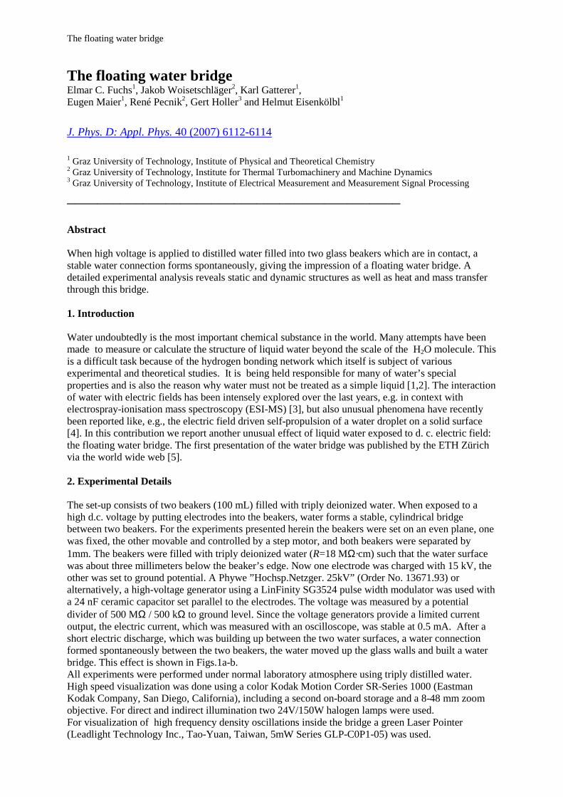
Figure 2. Thermographic visualisation of the water bridge. Immediately after the formation of the bridge (a) a slightly raised temperature (26°C) was observed (d), after 15 minutes of operation and a length of 10 mm (b) a higher temperature (46°C) was measured (e). With a longer, but thinner bridge (c, 15 mm length) the local surface temperature increases up to 60°C with “hot spots” at thinner diameters (f). While the low frequency oscillations were observed using a high speed camera system and turned out to be surface waves, a laser illuminated Schlieren visualization revealed additional inner structures oscillating inside the bridge at frequencies above 3 kHz. These high frequency oscillations were also affirmed by a green Laser Pointer focused by the cylindrical bridge forming a light sheet which oscillated in lateral direction at high frequencies. In combination with a high speed camera system the Schlieren visualization showed these inner structures in detail (figures. 3a,b).
The floating water bridge
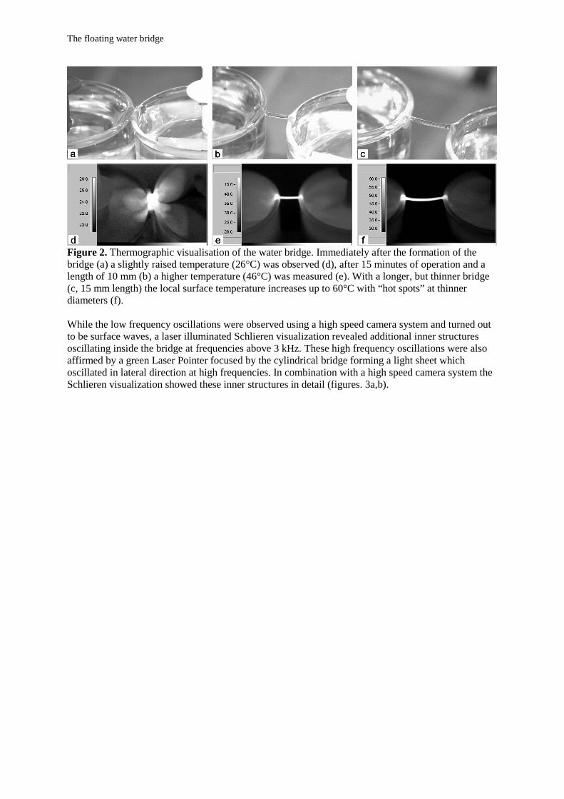
Figure 3. Density gradients within the water bridge, recorded with a high speed camera at 10 kHz frame rate (1/20000s exposure time), every 5th image is depicted. Figure 3a shows a single structure typical for a “young” bridge (5 min operation time). Figure 3b shows multiple structures (after 30 min operation time). In these images, the length of the bridge was approximately 10 mm. These structures were recorded with a 10 kHz frame rate (1/20000s exposure time), and every 5th image is depicted in figure 3. In this type of visualisation density gradients deflecting a parallel light beam in horizontal direction became visible. The light refraction by the cylindrical geometry of the water bridge was compensated for by an additional external cylindrical lens. The lateral gradients deflected the parallel light beam, forming focal spots in front of the bridge. These spots are visible in Figs. 3a,b for two different operation times after start-up of the bridge. Obviously, the surface waves which are likely to be caused by the surface tension were much slower than these moving inner structures. The high frequency oscillation of these inner structures were probably triggered by the waviness of the voltage supply, which is caused by the pulse width modulator, but smoothed by the capacitor. In every experiment, first a single inner structure can be observed, additional structures appear after a few minutes of operation. This decay might be caused by the increasing temperature of the bridge or by dust particles contaminating the water during operation. Adding a watery solution of soap enforced this structural decay and besides, the bridge became substantially thinner and disrupted in due course forming small droplets. From a stereoscopic observation the focal point formed in a parallel light beam by the lateral structure in figure 3a was located in space and the gradient in the refractive index estimated using the approximate focal length assuming a cylindrical symmetry. Together with the Gladstone Dale constant for water (2060·10-6 m3/kg) and the Clausius-Mosotti equation, a density change from the beakers edge towards the centre of the bridge in the range of 7% was found, in relation to the density of water at room temperature (998 kg/m3). A possible explanation
The floating water bridge
for this density change is an arrangement of the water molecules to form a highly ordered microstructure. 4. Conclusions It is reasonable to presume that the bridge forms between the two beakers due to the electrostatic charges on the water surface [6] producing a “cone-jet” as described by Hartman et al. [7,8,9]. Using a high starting voltage and due to the high dielectric constant of water, the electric field concentrates inside the water arranging the water molecules to form a highly ordered microstructure. This microstructure remains stable after the connections forms. Wider bridges therefore need higher voltages to obtain a stable equilibrium between the surface tension and the ordered dipole-dipole bonding force caused by the high electric field. Assuming microstructures in liquid water as proposed by Head-Gordon et al. [10], the high electric field could enforce smaller intermolecular distances leading to the density change observed in the experiments presented. An addition of ions distorts the structure due to the attraction between ions and water molecules. So, the build-up of hydrospheres around the dissolved ions is responsible for the instabilities or the break-up of the bridge in that case. Thus, adding a surfactant leads to an enforced structural decay and a lower surface tension. Both effects result in instability and disruption as described above. Due to the small-scale auto-protolysis there is a small conductivity (R=18 MΩ·cm) and an electric current flows through the bridge which in this case acts as a resistor and slowly heats up, with the thermal excitation disturbing the hydrogen bonding and enforcing decay. 5. References: [1] Stanley H E, Buldyrev S V, Franzese G, Giovambattista N, Starr F W, Philosophical Transaction of the Royal Society A 363 (2005), pp. 509-523 [2] Angell C A, Bressel R D, Hemmati M, Sare E J, Tucker J C, Physical Chemistry Chemical Physics 2 (2000), pp. 1559 - 1556 [3] Wei J F, Shui W Q, Zhuo F, Lu Y, Chen K K, Xu G B, Yang P Y, Mass Spectrometry Reviews 21 (2002), 158-162 [4] Masahide Gunji, Masao Washizu, J. Phys. D: Appl. Phys. 38 (2005) 2417-2423 [5] Uhlig W, Laboratory of Inorganic Chemistry, ETH Hönggerberg - HCI, Zürich, personal communication [6] Gañán-Calvo A M, J. Fluid Mech. 335 (1997) 165-188 [7] Hartman R P A, Brunner D J, Camelot D M A, Marijnissen J C M, Scarlett B, J. Aerosol Sci. 31 No. 1 (2000) 65-95 [8] Hartman R P A, Brunner D J, Camelot D M A, Marijnissen J C M, Scarlett B, J. Aerosol Sci. 30 No. 7 (1999) 823-849 [9] Hartman R P A, Borra J-P, Brunner D J, Marijnissen J C M, Scarlett B, J. of Electrostatics 47 (1999) 143-170 [10] Head-Gordon T, Johnson M E, PNAS 21 vol. 103 (2006) 7973-7977