The Finnish Envi ro n me nt - Valtioneuvosto
147
The Finnish Envi ro n me nt ENVIRONMENTAL PROTECTION The Finnish Background Report for the EC Documentation of Best Available Techniques for Pulp and Paper Industry . . .
Transcript of The Finnish Envi ro n me nt - Valtioneuvosto

The Finnish Envi ro n me nt
ENVIRONMENTALPROTECTION
The Finnish BackgroundReport for the EC
Documentation of BestAvailable Techniques for Pulp
and Paper Industry
. . .


The Finnish Environment 96
The Finnish BackgroundReport for the EC
Documentation of BestAvailable Techniques for Pulp
and Paper Industry
HELSINKI 1997
OOOOOOOOO_OOOOOOOOOOOOO O O O O O O OO O OMIN ISTRY OF THE ENVIRØNM ENT

MINISTRY OFTRADE AND INDUSTRY TECHNOLOGY DEVELOPMENT CENTRE
FINLAND
MINISTRY OF THE ENVIRONMENT
ISBN 952-1 1-0123-7ISSN 1238-7312
The Rnnish Environment 96Ministry of the Environment
Environmental Protection
Cover picture: Finnish ForestIndustdes Federation
Edita LtdHelsinki 1997
The Finnish Environment 96

IntroductionOOOOOOOOOOOOOOOOOOOOOOOOOOOOOOOOOOOOOOOOOOOOOOOOOOOOOOOOO.O.O.
The purpose of this report is to carry out the Finnish contribution to the exchangeof information in the Council Directive 96/61/EC concerning Intergrated PollutionPrevenfion and Confrol, article 16, and to the preparation of the Reference Document of the European Commission on the Best Available Techniques for Pulp andPaper Industry.
In the report, the manufacturing of pulp, paper and board grades which aremost important for the Finnish pulp and paper industry are discussed taking intoaccount production capasities, the used process technologies and their effects onthe discharges and emissions, solid waste generation and consumption of rawmaterial and energy.
The general description of Finnish pulp and paper industry is supplementedwith more detailed descriptions of six Finnish pulp and paper mufis representingdifferent types of products and production set-ups. The process technology of anew kraft pulp miii which started in the spring of 1996 is also described.
PI-Consulting Ltd was commissioned by the Ministry of the Environment,the Finnish Technology Development Centre (TEKES) and the Finnish Forest Industries Federation to compile this state-of-the-art report on the Finnish pulp andpaper industry.
The report was prepared by Rune Franzn, Esko Jantunen, Gun Björstäktand Göran Lindholm.
The project has been followed by a steering group with the following members:
Markku Hietamäki, Ministry of the EnvironmentAiri Karvonen, Ministry of the EnvironmentPirkko Molketin-Matilainen, Finnish Forest Industries FederationHeikki Uusi-Honko, Finnish Technology Development Centre (TEKES)Exja Fagerlund, Ministry of Trade and IndustryElina Karhu, Finnish Environment InstituteSeppo Ruonala, Finnish Environment Institute
The forest industry companies and equipment manufacturers have given valuable support to tMs project.
Helsinki February 1997
Ministry of the Environment
The Finnish Environment 96

0 . The Finneh Environment 96

lntroduction.3
Contents.5
Abbreviations 8
Executive Suiiniary’ 9
1 General description of the pulp and paper industry in WesternEurope 24
1.1 Pulp and paper production and consumption 241.2 Description of the pulp and paper production processes and raw material
used 28
2 General description of the pulp and paper industry in Finland... 332.1 PuIp and paper production 332.2 Finnish pulp and paper milis 342.3 Major process technology developments 34
3 Technical description of the most important pulp, paper andboard manufacturing processes in Finland 36
3.1 General 363.2 Woodhandling 373.2.1 Debarking 373.2.2 Chip screening 383.3 Chemical pulp 393.3.1 The krafi pulping process 393.3.2 Effects of process solutions in the kraft pulping process 483.3.3 Raw materiais, pulp yield 513.3.4 Energy coiisumption 513.3.5 Internal pollution control 523.3.6 Discharges and emissions into water and the air, generation of solid
waste 523.4 Mechanical pulp 583.4.1 Mechanical pulping processes 583.4.2 Screening and cleaning 613.4.3 Bleaching of mechanical pulp 613.4.4 Pulp properties and end-users of mechanical pulps 623.4.5 Raw materials, pulp yield and energy consuiuption 633.4.6 Discharges and emissions into water and the air, generation of solid
waste 643.5 Recycled fibre 653.5.1 Recycled fibre processes 653.5.2 Fulp properties and end use 673.5.3 Energy consumption 673.5.4 Discharges and emissions into water and the air, generation of solid
waste 673.6 Paper and board 683.6.1 General 683.6.2 Newsprint 713.6.3 Magazine paper 723.6.4 Woodfree printing and writing paper 743.6.5 Board 75
The Finnish Environment 96

3.7 External treatment of discharges and emissions, solid-waste handling 76
3.7.1 Waste water treatment 76
3.7.2 Treatment of einissions into the air 82
3.7.3 Handling of solid waste 83
3.8 Energy management 85
3.8.1 General structure of the pulp and paper industry energy sector 85
3.8.2 Specific characteristics of the pulp and paper industry energy sector 86
3.8.3 Boilers used in energy production 88
3.9 Monitoring of discharges and emissions into water and the air,
environmental management 89
3.9.1 Discharges into water 89
3.9.2 Emissions into the air 90
3.9.3 Environmental management systems 91
4 Reference Aulis 924.1 Newsprint 92
4.1.1 General 92
4.1.2 Debarking 92
4.1.3 Stock preparation for newsprint production (PM3) 93
4.1.4 Paper machine PM 3 93
4.1.5 Energy production 94
4.1.6 External treatment. Discharges and emissions into water and the air,
solid waste 94
4.2 Magazine Paper 96
4.2.1 General 96
4.2.2 Debarking 96
4.2.3 Stock preparation for PM 1 96
4.2.4 Paper machine (PM1) 97
4.2.5 Energy production 97
4.2.6 External treatment. Discharges and emissions into water and the ah,
solid waste 98
4.2.7 Monitoring of discharges 100
4.3 Bleached kraft market pulp 100
4.3.1 General 100
4.3.2 Debarking 101
4.3.3 Process description 101
4.3.4 Energy production and conswnption 103
4.3.5 External treatment. Discharges and emissions into water and the air,
solid waste 103
4.4 ECF bleached kraft pulp 106
4.4.1 General 106
4.4.2 Debarking 106
4.4.3 Kraft pnlp mili 107
4.4.5 Energy production 108
4.4.6 External treatment. Discharges and emissions into water and the air,
solidwaste 108
4.4.7 Water supply and treatinent 111
4.4.8 Monitoring of discharges 111
4.5 Integrated bleached kraft pulp and woodfree paper 111
4.5.1 General 111
4.5.2 Debarking 112
4.5.3 Kraft pulp miii 112
4.5.4 Paper miii 113
4.5.5 Energy production 113
The Finnish Enwonment 96

4.5.6 External treatment. Discharges and emissions into water and the air,solid waste 114
4.6 Integrated bleached pulp and wood-containing paper 1174.6.1 General 1174.6.2 Debarking 1184.6.3 Kraft pulp miil 1194.6.4 Paper miii 1204.6.5 Energy production 1214.6.6 External treatment. Discharges and emissions into water and the air,
soiid waste 1234.6.7 Modernization of the kraft pulp miii 1264.6.8 Discharge monitoring and analysis 128
5 Costs 1295.1 Investment costs 1295.2 Operating costs 129
6 A nei’ kraft pulp miii 1316.1 General 1316.2 Process description 1326.3 Externai treatment 134
7 Discussion 135APPENDIX 1 Standard analytical methods 139APPENDIX 2 Chlorine dioxide generation methods 140APPENDJX 3 Finnish puip and paper milis 141
Documentation 142
The Finnish Environment 96

AbbreviationsOOOOOOOOOOOOOOOOOOOOOOOOOOOOOOOOOOOOOOOOOOOOOOO
ADt Air dry torineAL Aerated lagoonAOX Adsorbable organic halogenAS Activated sludgeBOD7 Biochemical oxygen demand (7 days test)
CODCrMn Chemical oxygen demand (dichromate or permanganate)CSF Canadian Standard FreenessCTMP Chemi-thermo-mechanical pulpD Chlorine dioxide stage in pulp bleachingDAF Dissolved air fiotationDS Dry solidE Alkaline extraction in pulp bleachingECF Elemental cfflorine freeGNP Gross national productGW GroundwoodHC High consistencyHW HardwoodLWC Light weight coated (magazine paper)m3n m3 of a gas at atmospheric pressure and 20 2CMC Medium consistencyNOx Nitrogen oxides0 Oxygen stage in pulp bleaching sequenceP Peroxide stage in pulp bleaching sequence
Q Stage with chelating agent addition m pulp bleaching sequence
SC Super calendered (magazine paper)SGW Stone groundwoodS02 Sulphur dioxideSW SoftwoodTCF Totally chlorine freeTMP Thermo-mechanical pulpTot-N Total nitrogenTot-P Total phosphorusTRS Total reduced sulphurTSP Total suspended particulatesTSS Total suspended solidsX Enzyme treatment m pulp bleaching sequence
Conversion coefficients for energy
ltoe = 40.6GJ1MWh =3.6GJ
The Finnish Environment 96

Executdve Summary
The Finnish Background Report for the ECDocumentation of Best Available Techniques for thePuIp and Paper Industry
According to the Council Directive concerning Integrated Pollution Preventionand Control (96/61/EC) the term ‘best available techniques’ shall mean the mosteffective and advanced stage m the development of activities and their methodsof operation which indicate the practical suitability of particular techniques forproviding in principle the basis for emission limit values designed to prevent and,where that is not practicable, generally to reduce emissions and the impact on theenvironment as a whole:
-‘techniques’ shall include both the technology used and the way in whichthe installation is designed, bufit, maintained, operated and decommissioned,
-‘available’ techniques shall mean those developed on a scale which allowsimpiementation in the relevant industrial sector, under economically and technically viable conditions, taking into consideration the costs and advantages, whether or not the techniques are used or produced inside the Member State in question, as long as they are reasonable to the operator,
-‘best’ shall mean most effective in achieving a high general level of protection of the environment as a whole.
IntroductionFinland is located north of latitude 60° N and is part of the coniferous forest beitsurrounding the northern hemisphere. Almost 70% of the Finnish land area iscovered with forest. Due to the favourable dimatic influence of the Gulf stream,the productivity of the Finnish borealic forest is quite high.
The Finnish pulp and paper industry together with the associated engineenng and chemical industries is the dominant sector in the Finnish economy. In1995 the total annual production of chemical pulp was about 6 million tonnes andof paper and board 11 million tonnes.
In 1995 the total Finnish consumption of primary energy was 31.7 Mtoe. Ofthis, approximately 32% was of domestic ongin (table 1A). The consumption ofelectrical energy was 69.0 TWh (table 1B). The production of chemical pulp includes the recovery of the process chemicals. The cycle includes incineration of thespent cheinicals and the dissolved wood in a recovery boiler, which produces energy. From table 1A it can be seen that nearly 10% of total primary energy comesfrom this source. The net consumption of energy, thermal and electrical, in theFinnish pulp and paper industry was 9.2 Mtoe and 22.9 TWh respectively in 1995.The harsh winters in Finland have a pronounced impact on energy consumption.
The Rnnsh Enronment 96 0

Table IA. Total consumption of primary energyja Finland in 1995.
MtoeImported 21.5
Oil 8.6Coal 3.3Natural gas 2.9Nuclear 4.5Electric 2.1
Domestic 10.2Hydro 3.2Black liquor 2.8Wood 2.0Peat 1.6Industrial waste heat 0.6
Total 31.7Pulp and paper 9.2
Tabio IB. Generation and consumption of electricityin Finland ja 1995.
TWhGeneration 69.0
Hydro power 12.8Nuclear power 18.1Condensation power 8.8District heat power 11.4Black pressure power 9.5Net imports 8.4
ConsumptionIndustry, total 37.3
Pulp and paper 22.9
The development of Finnish forestry is based on long-term experience. The syste
matic forest management has resulted in a growth that exceeds the feffing, which,
in practice, means that a considerable amount of carbon dioxide is bound because
of the strong growth of the well-managed forest. Legislation passed as eariy as in
1928 obliges Finnish forest owners to regenerate harvested forest. The law, which
is enforced by forest officials, in effect prohibits not only iocal harvesting in excess
of locai re-growth but aiso excessive clear feffing on a national scale.The principle of ecological sustainability has become increasingly important
in Finnish forest management. According to this principle, the commercial utiliza
tion of the forest must not endanger the diversity of different species living there.
As much as 10% of Finland’s forested area is protected from ali commercial use, a
very high figure in international terms. Protected forests are government-owned
and situated in eastern and northern Finland. For small, privately-owned forests
in southern Finland, iarge-scale protection is ruled out. Under the new regime
aimed at the preservation of biodiversity, no fertilizers or intensive soil-prepara
tion methods are used to boost growth. Further measures aimed at retaining the
O The Finnish Environment 96
variety of indigenous biotypes include the creation of protected ecological corridors and leaving an increased amount of standing dead wood as well as fallendead wood to decompose in the natural way.
Approximately 80% of the Finnish pulp and paper industry production isexported to Europe and 10% is used domestically. The production is almost entirely based on primary fibre and, therefore, Finland plays an important role as asupplier of primary fibre to the European and international paper and board industry that utilizes recycled fibre.
The production of pulp, paper and board for the international market placeis a demanding task from several standpoints. In order to succeed, the producthas to meet stringent quality specifications. The generally applied concept of totalquality includes improved productivity and minimum environmental impact aswell as excellent perforrnance at the customer’s plant and a top-quality product atthe consumer’s end of the chain.
The Finnish pulp and paper industry actively co-operates with related engineering and equipment suppliers in the development of better production technology. The principal goals set for this work are the more efficient use of raw materiais and energy as well as a reduced total environmental impact.
The size of the production units has increased, which has made a substantialgrowth in production possible in spite of the shutdown of old mifis. A typicaltrend in the Finnish paper and board industry has been the directing of production towards products fetching a higher price arising out of the use of special skillsand advanced production methods. Pulp production has abandoned the use ofelemental chlorine in bleaching and offers a diversity of pulps to suit the customer’sneeds. Recent process developments in kraft pulping have led the Finnish industryto abandon the sulphite pulping process. The development since 1970 is characterized by an increase in the total paper production capacity of 100% and a switch toimproved and specialized products.
The decrease in the number and increase in the size of the production unitshas resulted in an iniproved environmental situation. Improved production techniques in combination with internal pollution prevention and external abatementmeasures have been vital ingredients in the investment programmes. The degreeof integration has also increased, resulting in more efficient raw material usage,efficient energy production and usage as well as advanced internal pollution abatement. The discharge of pollutants into the waterways has decreased during theperiod to less than 10% (in 1995 30,000 tonnes of BOD7 and 25,000 tonnes of suspended solids) of the 1970 level, and the emission of sulphur into the air from theprocess and on-site energy production was 9,300 tonnes in 1995. Figure 1 demonstrates the development of production of pulp, paper and board and discharges and emissions into waterways and the air from the chemical pulping processes.
The Finnish Enronment 96

Figure 1. Production of pulp, paper and board 1970-1995. Discharges and
emissions of pollutants into waterways and the air from the chemical
pulping processes (emissioris from the energy production in boilers for wood
waste and fossil fuel on site is not included).
The Finnish Enironment 96
Finnish forest industry and water protection
Productionmilliori tonslyear
10-jOsuspended solids Ioad 1BOD7 Ioaci
Effluerit Ioad1000 tonslyear
8-
1000
PPerd /paperboard
Cheniical pulp
- 800
6-
4-
j
- 600
400
1ll - 200
-01950 1955 1960 1965 1970 1975 1980 1985 1990 1995
Total Sulphur Emissions of Finnish PuIp IndustrySulphur dioxide and total reduced sulphur combounds (TRS)
1000 t(S)!a60
50
4D
30
20
10
0
FFIF & Minisiry ot Tra& and ndustry
19B01981 1982 138319841985198619871988198919901991 1992199319941995

Paper and boardPaper and board are made from a wide variety of fibres, minerais and additives toa certain thickness and basis weight grade specifications. The products are sold bythe tonne.
Products with a basis weight between 20 and 100-150 g/m2 are normally named paper. Products with basis weights higher than this are called board.
The raw materiais and principal processes in paper and board productionare similar. Board is used for other purposes than paper, and, in addition to providing printabilit board has to be rigid and stiff in order to protect products packedin containers made out of board.
Production ofpulpThe main constituents of wood are carbohydrates and lignin. In the carbohydrategroup, the most common polymer on earth, cellulose, is the backbone of the trees.Cellulose forms fibres which are glued together with lignin, forming a light andstrong wooden structure.
Early in written history, man learned that fibres from plants can be formedinto sheets with the aid of water. For centuries paper was made of fibres fromarinual plants and wool recovered from old clothes, rugs. It was not until the second half of the l9th century that the principal inventions of wood pulping weremade. The impiementation was immediate and smce then ordinary paper hasbeen made from wooden fibres. Wood suitable for defibration is found ail over theworld, both hardwood and softwood.
Timber intended for pulping is harvested, cut into logs and transported tothe production site.
For most pulping processes the bark has to be removed. The debarking oflogs is done mechanically, using water for washing and in wmter time fordeicing.
Wood residues from sawmils, sawmffl chips, are also ulilized as fibre rawmaterial in chemical and mechanical pulping.
Chemical pulpingThe liberation of fibres is achieved by applying either chemical or mechanical energy to the wooden material. In chemical pulping a mixture of wood chips and anaqueous solution of chemicals is heated and the ligiiin dissolves. Residual ligninaffects the whiteness of the pulp and further processing, cailed bleaching, removes the dark colour.
Sulphate pulping, also known as the kraft process, with ali its process atternatives and the possibility of using a wide vanety of raw materiais as well as producing a wide variety of pulp grades has become the dominant chemical pulpingmethod.
In kraft pulping, the cooking liquor is separated from the fibres after cooking. TMs so-called weak black liquor holds the cooking chemicals and approximately 50% of the original wood. Chemical pulp of different yield leveis is made tomatch the requirement of the final product in which the pulp is to be used. Theweak black liquor is concentrated by evaporation to a dry-solids content of at least70%, but preferably over 80%, before incineration in a recovery boiler. A high solids content in the liquid going to combustion results in better control of the fur
TheFinnishEnvronment96

nace, higher thermal efficiency and the successful prevention of sulphur
emissions. The incineration residue is dissolved in water, and this solution is furt
her processed to regenerate ftesh cooking liquor.In a modern kraft pulp mifi wood fibre is further delignified prior to final
bleaching. In order to recover additional recoverable dissolved organic solids and
used chemicals, the pulp is washed using counter current flow and the liquid is
combined with the weak black liquor, evaporated and burnt in the recovery boi
ler.This extended delignification is performed by applying oxygen delignifica
tion or, preferably, a combination of extended cooking and oxygen delignification.
The use of efficient washing equipment is an essential part of the process.
The colour of the washed pulp is dark brown and it has to be bleached before
use in white paper and board products. The use of unbleached pulp is limited tobrown products, such as brown liner and sack paper.
In the bleaching, chlorine chemicals are today partially or totally replaced by
bleaching agents such as oxygen, ozone and hydrogen peroxide, chemicals which
can be incorporated into the chemical recovery cycle without side-effects.
The amount of effluent from a bleaching plant is in the range of 5 to 40 m3/ADt.
A modern kraft pulp mii produces more energy than it consumes. The ener
gy production is based on using the dissolved solids in the black liquor as fuel inthe recovery boiler. Bark and other wood residues are also valuable biofueis used
on site in a boiler for solid fuel or delivered to a nearby energy production uniL
Malodorous gases formed in the process are cornprehensively collected. Con
centrated gases are burnt, either in a separate furnace equipped with a waste heat
boiler or in the time kiln, where it replaces fossil fuel. Weak malodorous gases areeither washed with an alkaline washing liquid or burnt in the recovery boiler or
the time km.
Mechanical pulpingMechanical pulping, means that the wooden structure is broken by applying a
mechanical force, liberating fibres and fibre fragments. The pulp (groundwood,
refiner puip etc.) gives the paper properties, such as a smooth surface and iow
opacity, which are needed for successful printing. Mechanical pulp production is
generally integrated with the production of paper and board.The yieid in mechanical pulping is 95-98 %, which means that 20-50 kg of
wooden substance per tonne of pulp dissolves in the water present during the
defibration. The dissolved material consists of simple carbohydrates (sugars), fats
(triglycerides), fatty acids, rosins etc. and inorgariic components.The initial brightness of mechanical pulp is moderate and for some products
the pulp is brightened. The two principal chemicais used for bleaching mechani
cal pulp are the reductive sodium dithionite and the oxidative hydrogen peroxi
de. Bleaching with peroxide involves the use of caustic, which causes the decom
position of wooden material, and an additional yieid loss of 15-25 kg/ADt has been
observed.The components dissolved during defibration and the peroxide bleaching of
mechanicai pulp affect the chemical balance in the process. In order to decrease
disturbances on the paper or board machine, the pulp is washed by pressing be
fore use, or neutralizing chemicals are added.Water-soiuble components in wood are readily biodegradabie and, there
fore, the pollution potential is easy to remove by biological treatment of the efflu
ent.
O The Einnsh Environrnent 96

Paper and board productionWater is necessary as a transporting, washing and cooling medium in connectionwith pulp and paper production. The cellulose fibre swells in water and the surface is chemically activated. Without this natural property conventional paper making would be impossible. In this process a mixture of fibres and additives according to the recipe is diluted with water, stirred and dewatered. After the primaryseparation of the fibrous material and the water, more water is removed from theweb by pressing. At this stage the fibres come close enough to form preliminarybonds which are confirmed and strengthened when the paper is dried. The natural paper is held together by hydrogen bonds between the individual cellulosefibres.
The production equipment has developed considerably, bringing new products with superior properties onto the market. For instance, within twenty yearsthe production speed of machines producing newsprint or magazine paper hasincreased from 60 km/h to over 90 knVh. In combination with wider machines, thecapacity has increased to the double per production unit.
Both paper and board can today be produced at lower basis weights thanearlier without a loss of any essential properties. Therefore, less paper, by weight,is needed to produce a newspaper or magazine, or less board is needed for a boxor container. The significance of this development for better total efficiency andreduced environmental impact cannot be over stated.
Table 2 shows the most typical paper and board products and their composition.
Table 2. Composition of paper and board.
Paper and board grade CompositionNewsprint 100% TMP
90-100% DIP10 - 0% bleached kraft pup
Magazine paper- SC 50- 60% mechanical pulp
10- 25% bleached kraft pulp15- 35% minerais
- LWC 25- 45% mechanical pulp25- 40% bleached kraft pulp30- 40% minerais
Fine paper 60- 75% bleached kraft pulp25- 40% minerais
Folding box board 50% bleached kraft pulp40% mechanical pulp10% minerais
Kraftliner 100% kraft pulpFluting 100% NSSC pulp
SC super calenderedLWC light weight coated
TheFinnishEnvronment96
EnergyIn general, the heat energy used by the Finnish pulp and paper industry origina
tes from combined power and heat generation. High-pressure steam is generated
from a wide variety of wood-based fueis such as bark, black liquor and sludge as
well as from peat, coal, natural gas and heavy fuel oil. The high-pressure steam
releases part of its potential energy in a turbo-generator, and the thermal energyrecovered by condensing is used for drying the products and heating the premises. The overail thermodynamic efficiency in this kind of system is as high as
80-88%.Modern mechanical pulping incorporates pressurized pulping methods which
make energy recovery possible in the form of Iow-pressure steam. This steam isused for product drying. The energy recovered is ir the order of 1,000 to 1,500kWh/tonne of pulp, representing 30-40% of the total energy consumption in thethermo mechanical pulping.
A kraft pulp miii is more than self sufficient in energy, both electrical andheat. The amount of surpius electricity ii modern Finnish kraft pulp milis is about500 kWh/tonne. Integrated pulp and paper production provides optimal conditions for energy efficiency.
The recent trend to using a gas turbine generator followed by a steam boilerand a turbo-generator (a “combi” power plant) increases the share of electricalenergy compared with conventional power generation, which is preferable in theproduction of mechanical and deinked pulp.
Wood-based energy used by the Finnish pulp and paper industry is approximately 3.5 Mtoe/a (40% of the total energy consumption). The structure and efficiency of on-site energy generation contribute in a positive way to the striving for
a considerable decrease in air poilution.Table 3 presents figures on energy consumption for key products in the Fin
nish pulp and paper industry.
The Finnish Environment 96

Table 3. Specific heat and electrical enery consumptionand self-sufficiency for some key products inthe Fdnnish pulp and paper industry.
Product Heat energy Electrical_energyConsumption Self- Consumption Self
sufficiency sufficiency(GJ/t paper) (%) (MWhJt paper) (%)
NewsprintIntegrated withproduction of
SGW 4.8-5.8 5-10 1.7-2.1 10-15PGW 4.8-5.8 10-20 1.8-2.2 10-15TMP 4.8-5.8 70-100 2.4-3.3 10-15
Magazine paper(SC,LWC)Integrated withproduction of
SGW (35%) 4.5-6.0 2-5 1.8-2.0 —5PGW (40%) 4.5-6.0 5-10 2.0-2.2 —5TMP (45%) 4.5-6.0 30-50 2.3-2.6 —5
(ash contnt 30%Woodfree paperIntegrated withproduction ofbleachedkraft pulp 14-18 70-80 1.0-1.2 85-105Non-integratedproduction 7.0-7.8 0 0.7-0.9 0Bleached marketkraft miii, 13-15 100-120 0.6-0.8 110-200Woodfree paper: paper with max. 10% mechanical pulp
Prevention ofpollution
Discharges into water
The sources and types of wooden components transferred into the water phasehave heen indicated above. Wood components suspended and dissolved in theprocess water must not be allowed to accumulate in the process because of theadverse effects on production efficiency and product quality. The productionmachinery and equipment need clean water for washing, lubrication, cooling andsealing. Part of this water leaks into the main process giving rise to excess processwater, which has to he removed.
In pulp production, fibres are dispersed and suspended in water, and in papermaking water is separated from the suspension. The water separated on thepaper machine is called white water and is reused in the pulping. The fresh waterused for different purposes leaves the process as excess white water. The excesswhite water contains solid components which are usable in the product and,therefore, the water is clarified. The separated solids are returned to the papermachine and the clear filtrate is discharged.
The Finnish Environmerit 96

The fresh water used in the process gives rise to a roughly equal amount of efflu
ent. The discharged amount of effluent can be decreased by replacing fresh water
with clear filtrate in selected areas. Simultaneously the concentration of dissolved
and dispersed pulp and paper components in the white water wil increase. If the
components are allowed to accumulate, the production efficiency and the pro
duct quality are negatively affected. The efficient removal of dissolved and dis
persed colloidal material, in addition to, or in combination with, the separation of
suspended solids makes it possible to reuse the water. The reuse of internally
treated water replacing fresh water is referred to as water system closure and is astrongly emerging technology.
The total amount of effluent discharged in the pulp and paper industry is
approximately 10-50m3/tonne of product. As a resuit of new production facilities
where partial fresh water replacement by internally treated water has been imple
mented, the specific water consumption (effluent discharge) has decreased to theIower end of the range mentioned. The modernization of old milis has given simi
lar results.Effluent extracted from the process contains dissolved and dispersed
substances originating from the raw materiais. Most of these substances are
biodegradable and, if discharged into rivers or lakes, pollution takes place,
causing oxygen depietion and eutropKication.The biological treatment of effluents is predominantly implemented in the
pulp and paper industry (figure 2). The use of biological treatment by the Finnish
pulp and paper industry started at the end of the 1970’s when the first aerated
lagoons were introduced. The lagoons were equipped with the secondary sedi
mentation of suspended solids. The Iocal pollution level dropped considerably,
and the effect could be observed as an improvement in the water quality in the
recipient.In the middle of the 1980’s the first activated sludge plants were built, start
ing a new era in water pollution abatement in the Finnish pulp and paper in
dustry. In activated sludge treatment the biodegradable substances are removed
very effectively (table 4A). Wood contains substances which protect the tree against
pests. These substances gives the effluent acute toxic characteristics. The acute
toxicity of the effluent, measured as LC5O for water flea (Daphnia niagna), is com
pietely removed by activated sludge treatment.Simultaneously with the impiementation of activated sludge treatment, an
aerobic treatment was tested and found useful for certain applications. Because
biogas is generated as a by-product in the anaerobic treatment of highly concen
trated effluents, this has an energy advantage over the aerobic treatment.
Of the wood components, lignin shows high resistance to biodegradation
under the conditions prevailing in biological effluent treatment. The residual frac
tions of lignin present in the treated effluent are visible as a brown colour in the
water. The natural brown colour in Finnish inland streams also comes from frac
tions of lignin as humic acids, originating from disintegrating plant material in the
marshes.The reduction rates in the activated sludge treatment of waste water from
kraft pulp and paper production is shown m table 4A.
Table 4B shows the specific discharge into the recipient after external treat
ment from the production of bleached kraft pulp and wood-containing paper in
Finland in 1995.
O The Finnish Environment 96

Table 4*. Reduction ratestreatment (%).
in activated slude
Krafi pulp Wood-cont.papr **)
TSS >95 >95COD 40-70 70-90BOD7*) 85-98 95-99tot-P 40-85 40-85*) 1.16 - BOD5**) wood-containing paper: > 10% mechanical pulp
Specific dischares into the recipientafter ezternal treatment in FinlandIOO5,averae and variation
Bleached kraft Wood-cont.pulp paper **)
TSS (kg/t) 2.0 (0.2-6.0) 0.4 (0.3-1.0)CODcr (kg/t) 32 (13 -85) 2.4 (1.6-5.0)BOD7 *) (kg/t) 1.5 (0.2-12) 0.2 (0.1-1.2)tot-P (g/t) 35 (5.0-95) 4.0 (3.2-13)
Figure 2. Biological treatment plants in the Finnish Forest Industry in Dec. 1996.
The Finnish Environment 96 O
Table 4B.
*) 1.16 BOD5**) wood-containing paper: > 10% mechanical pulp
Biological Treatm tsin the F sh Fore /Ifl try
Aerated lagoon
O Activated sludge piani /-5 5
O Anaerobic plant
Emissions into the airThe emissions into the air from the pulp and paper industry are mainly connected
with the generation of energy and recovery of cooking chemicals. The kraft pulp
ing process gives rise to small amounts of malodorous, sulphur-containing gases,which are sensed by the human nose at very low concentrations.
Emissions into the ah ftom the incineration of fueis and spent liquors consist
of particulate matter, called fly ash or dust, and different gases. In addition to the
emission of carbon dioxide, which is not discussed here, sulphur dioxide and oxi
des of nitrogen are considered the most important pollutants.
Flue gases are treated for the removal of particulate matter first in cyclones
for coarse separation, and finally in electrostatic precipitators, where the remain
ing dust is almost entirely retained.Emissions of both reduced sulphur compounds (TRS) and sulphur dioxide (S02)
from kraft pulp recovery boilers have decreased considerably as a resuit of modi
fications made to the black liquor treatment. An increased solids content in the
black liquor results in a higher temperature in the incineration, the increasing
amount of vaporized sodium binds the sulphur and the emission of the latter is
eliminated.The highly concentrated malodorous gases ftom the kraft pulping are col
lected and incinerated in a separate boiler, in the lime kun or in the recovery boi
ler, and weak malodorous gases are treated with alkaline washing liquor or
preferably incinerated in the recovery boiler. The collection systems have develo
ped and are today extended to cover most of the sources for bad smells in a kraft
pulp miii.Oxides of nitrogen are formed predominately from nitrogen-containing com
pounds present in the fuel. If the incineration temperature is above 1,0000 C so
called thermal nitrogen oxides start to form through oxidation of the atmospheric
nitrogen. The formalion of nitrogen oxides is partially avoided by tuning the mci
neration itself.In a modern plant, the incineration of solid fueis is done in a fluidized bed
boiler. This technique gives good combustion efficiency at a moderate temperatu
re, resulting in cleaner flue gases.
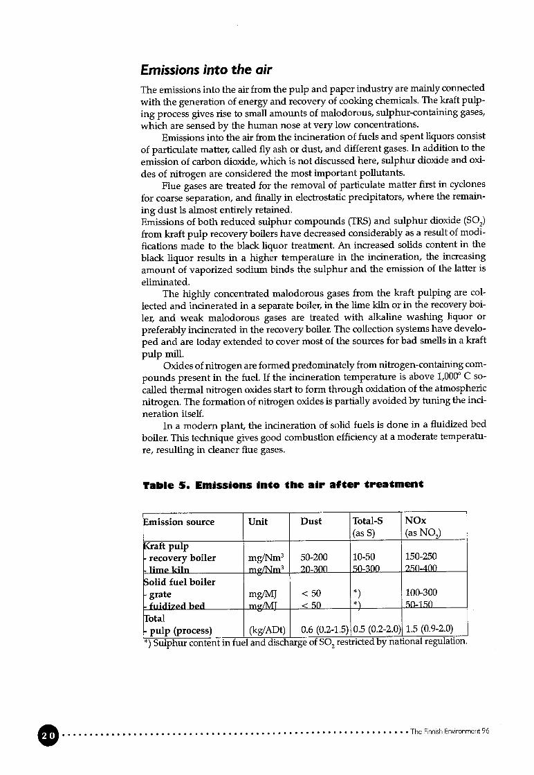
Table 5. Emissions into the air after treatment
mission source Unit Dust Total-S NOx(as S) (as NO2)
(raft pulprecovery boiler mg/Nm3 50-200 10-50 150-250Ilme kun mgfNm3 20-300 50-300 250-400
o1id fuel boilergrate mg/MJ < 50 *) 100-300
fuidized bed mg/MJ < 50 *) 50-1.50
btalpulp (process) (kg/ADt) 0.6 (0.2-1.5) 0.5 (0.2-2.0) 1.5 (0.9-2.0)
*) Sulphur content in fuel and discharge of S02 restricted by national regulation.
O The Finnish Environment 96

Solid wasteThe production of pulp, paper and board in combination with pollution abatement gives rise to solid waste of various compositions.In general, primary sludge from effluent treatment is combined with surpius biosludge from secondary treatment, pressed to a dry-matter content sufficient fordestruction by incineration, with energy recovery.
The principal composition of the sludge depends on the type of product. Inthe case where mineral pigments are used, the ash content of the sludge can beconsiderable, making incineration uneconomical.
In the deinking of recycled fibre, the resulting sludge is combined andpressed with other sludge and burnt. The amount of solid waste can be as high as40%, by weight, of the recycled paper treated.
Solid waste from the power plants is in the form of grate and fly ash, whichare disposed of by landfilhing or used for different applications such as soil conditioning.
Ash from bark contains the inorganic trace elements from the frees and canpossibly be returned to nature as a fertilizer.
NoiseThe main sources of noise in the Finnish pulp and paper industry are wood-handling, compressors, fans and ventilators. The probiem is addressed and at millslocated in the vicinity of towns and villages the noise sources have been insulated.
Environmental control and managementThe monitoring of the emissions and the effects of the emissions on the environment are based on self-monitoring, which is carried out according to provisionsincluded in the permit or in an emission control programme approved by theregional authority.
The monitoring programmes and the reports on the emission and recipientmonitoring are available to the public. Monitoring results of emissions are regularly reported, and each mifi is obhged to submit an annual report to the authorities.
Important factors connected with the control of emissions are the flow measurement, sampling method, handling and storing of sampies, analysis methodand accuracy, and the calculation and reporting of the results. Within Finland themonitoring results are comparable, due to the use of standardised methods, practices and guidlines given by the authorities.
It is most important to note that great care has to be taken when comparingdischarge figures from different countries. Although the analytical methods arebeing internationally standardised, the methods of sampling, pre-treatment andstatistical calculation make the correct interpretation difficult. The monitoring ofemissions into the recipient should therefore be harmonized within the EU.The environmental management systems in use in the Finnish chemical forestindustry are based either on the BS 7750, the ISO 9000 or ISO 14000 series standards or the Eco-Management and Audit Scheme (EMAS), and they are usuallylinked to the quality systems of the company concerned. The effectiveness of thesystem is ensured by regular reviews and audits aiming at continuous improvement of environmental protection practices.
The Finnish Environment 96

CostsRegular investment in the modernizafion of existing mifis has enabled the industry
to maintain its competitiveness continuously, and this, too, is a guarantee of goodenvironmental performance. The impiementation of internal treatment at the source has considerably decreased the losses of raw materiais, chemicals and energy.
The external treatment of discharges and emissions, gaseous, liquid or solid,includes capital and operating costs. A new production plant is constructed according to stringent efficiency demands, and, therefore, internal measures are highlighted, resulting in less external investment.
Both the investment cost and the operating cost are, in principle, specific tothe type of treatment technology.
The technological development has brought to the market machinery whichworks at a higher efficiency than similar equipment in old milis. It is, therefore,evident that new instailations achieve a lower consumpfion of raw materiais andutilities and hence a lower primary environmental iinpact for a given production.
In every miii, modern or not, it is possible to segregate streams and integrateprocesses in order to save energy and raw material or, in other words, limit theuse of natural resources.
ConclusionsThe ultimate goal for any production is to utilize available resources in the mostefficient way. Ali Finnish pulp and paper companies have signed the documenton sustainable development issued by the ICC and they adhere to these principles in their everyday operations.
The production of pulp in Finland is normally integrated with paper andboard production in order to achieve optimization regarding the consumption of
utilities and total efficiency.In Finland the engineering and other pulp and paper-related industries ope
rating worldwide provide pulp and paper production technology, both hardwareand software, to different countries. This is one reason why Finnish industy putsbig efforts into the development of processes with a lower total water consumption in the pulp and paper production.
In addition to wood or other fibrous raw material, the use of water is necessary in the process. It is a fact that suitable water for the processes is not foundeverywhere or ali the year round. The treatment of water that has been aireadyused for reuse in the process is most important in regions where water is a limitedresource. This is not the case in Finland but, nevertheless, Finnish industry hasincorporated this important question early into the process development.
It has been pointed out that most of the dissolved pollutants are readily bio
degradable and, therefore, biological treatment, today as an external addition, can
and has to be incorporated in a system for water reuse.From the above it is evident that in pollution abatement several methods
have to be combined in order to achieve the desired resuit.The integration of processes, for instance the integrated production of pulp
and paper, which is typical of the Finnish forest industry, is an important compo
nent of high, overail efficiency, which simultanously means low pollution of the
environment.The main streams of wasted material from the process are in the form of
liquid, gaseous and solid waste. The treatment for pollution removed ftom one
fraction influences the other and, therefore, the total system has to be carefully
scrutinized for minimal environmental impact.
The Finnish Environment 96
By applying different methods and combinations of methods to segregatedstreams it is possible to optimize costs and benefits. The impiementation of thebest combination of available technology is in the interests of the industry itselfand the driving force is improved overail performance.
In the modern Finnish pulp and paper industry, process efficiency and poilution prevenfion are tightly bound together through sophisticated productionprocesses and managerial principles.
The Finnish Environment 96

General description of the pulp
and paper industry in Western
Europe.......................................................
1.1 PuIp and paper production and consumption
In developed societies the use of a multitude of paper- and board-based products
is everyday reality for most people. Paper as we know it today has been in
existence for over a thousand years, and it is stili competing very successfully with
the most modern electronic information media and the most advanced plastic
and composite packaging materiais. A look at the main functional uses of paper
and board clearly shows what versatile raw materiais they are.
Table 1.1.1 Functional use of paper and board
Functional use Typical grades Typical end products Important trends(se’ secl-inn )
Information - Newsprint - Newspapers Increased use of multicolour
- collection - Coated and uncoated - Journais printing and copying
- distribution magazine (SC and - Books Electronic media taking over
- storing LWC) - Computer printouts banking and trading documents
- Coated and uncoated - Xerographic copies Increased recyding as rawwoodfree printing - Inserts materialand writing - Illustrations Increased use of additives
Packaging - Lmer - Bags Increased use for distribution of
- transportation - Sack - Boxes food- distribution - Corrugating medium - Wrappings Regaining market from plasfics
- protection - Folding box board because of easier recyclability
- Liquid packaging board - Containers as a raw material
- Wrapping Increased use of composites
Hygienic - Tissue - Toilet tissue Use increases with general
- personal care - Towel - Diapers living standard.
- disease - Sanitary - Facial tissue End of the chain for theprevention - Industrial towels recycing of fibres
- Hospital clothingSpeciality - Official papers - Notes An ever-increasing number of
- a great variety - Filter paper - Stamps new applications
- Fire resistant papers - Air filters- Coffee filters- Baking paper
A trend not shown in table 1.1.1 is that more and more functions in many pro
ducts are combined, such as printing on packages and towels.
One of the mam reasons for the continuous use of paper and board is that
they are mainiy produced from a renewable raw material, i.e. vegetable fibres,
and that, to a large extent, these fibres are reusable over and over again. If the
fibres originate from agricultural crops, straw, bagasse (sugar cane), or grasses such
The Finnish Envwonment 96

as reed, there is a fresh supply every year, and if they are taken from trees, there isa new supply about every seven to sixty years depending on the species, growthplace and other uses of the wood.
Historically, pulp and paper mifis in Europe were, and mostly stiil are today,located close to some body of water as the availabifity of water plays a major rolein the production process. Rapids m rivers were used to generate the power needed for the pulping, and the waterways were used for the transportation of boththe raw materiais and the products. When wood became the dominating fibresource, the size of the milis started to grow, and frequently the milis were broughtas close to the raw matenal as possible. The use of market pulp and, more markedly, the increased use of recycled fibre now favour locating new mifis close to themarket for both raw-material procurement and product disposal reasons.
The European pulp and paper industry has undergone, and is stili undergomg, a major metamorphosis in that it is developing from being a major pollutant of rivers, lakes and the seato an ahnost clean industry. An outstanding exampleis the development in Finland during the last twenty years. The production ofpulp has doubled during that time, but the release of organic substances has fallento less than one- tenth of the level twenty years ago. Thus the efficiency of polluilon abatement with regard to these pollutants has improved more than twentyfold.
The consumption of paper and board is sfrongly related to living standards,and over long-term periods there is a strong correlation between the increase inthe consumption of these products and the growth in the GNP (Gross NationalProduct).
The Finnish Envonment 96

Table 1.1.1 Per capita consumption 1995(Production plus imports minus exports.Cbanges in stocks aro not taken into account)(Pulp and Paper International (PPI) ‘90)
ontinent Region Country Apparent per capitaconsumption
kg/year
urope 93
European Union 171Austria 192Beigium 237
Denmark 214Finland 304France 164Germany 194Greece 82Ireland 102Italy 140Luxembourg 168Netherlands 201Portugal 82Spain 129Sweden 210United Kingdom 194
Other Western Europe 194Eastern Europe 19
CIS1 13Czech Republic 37Estonia 67Hungary 28Poland 40
Jorth America 322Canada 230USA 332
sia 25China 22Indonesia 14Japan 239Korea 147Thailand 37Turkey 27
)ceania 152Australia 187New Zealand 213
outh America 31Brazil 35Chile 37
enlial America Mexico 36
frica 6
Egypt 9
South Africa 43
bt1 worhl 49
1) The CIS is defined as the former USSR. Estoma, Latvia and Lithuania are not included.
The Finnish Environment 96

As is shown in table 1.1.2, there is a tremendous variation in the worldwide consumption of paper per capita. Even within Europe the differences are dramatic. Asimple mathematical calculation shows that the EU countries that are now belowthe EU average would need an additional capacity of 5.9 million tonnes per yearto reach the present average. As the average is growing, it can be safely predictedthat pulp, paper and board manufacturing wffl be a growth industry for manyyears to come.
?able 1.1.3 Apparent consumption and productl.n ofpaper and board within die EU (PPI ‘96)
Country Apparent con- Production Balancesumption (1,000 tonnes) (1,000 tonnes)(1,000 tonnes)1994 1995 1994 1995 1994 1995
European Union 59,752 63,872 45,190 69,726 -14,562 +5,854ustria 1,489 1,550 3,603 3,599 +2,114 +2,049Pinland 1,357 1,552 10,910 10,942 + 9,603 + 9,3903weden 1,648 1,857 9,284 9,169 + 7,636 + 7,312rotal 64,246 68,9871) Austria, Finland and Sweden included.
When Austria, Finland and Sweden entered the European Union in 1995, the paper and board supply situation changed from a 25% deficiency to a surpius ofalmost 10%. Finland is the country showing the largest export capacity. The EU isstifi a net importer of primary fibre, as is shown in table 1.1.4.
Table 1.1.4 Apparent consumption and production ofpulp (primary fibre) (PPI ‘96)
ountry Apparent con- Production Balancesumption (1,000 tonnes) (1,000 tonnes)
______________ (1,000 to ‘es)1994 1995 1994 1995 1994 1995
luropean Union 18,791 37,351 9,493 31,835 -9,298 -5,516aistria 1,925 1,919 1,595 1,620 -330 -299in1and 8,552 8,894 9,962 10,089 +1,410 +1,195;weden 7,490 7,868 10,097 10,187 +2,607 +2,319
btal 36,758 31,147
Sweden is the Country with the highest pulp export capacity in the EU. Within theEU the countries with large forests, not only Finland and Sweden but also France,Germany and Austria as weil as the countries with large piantation forests, i.e.Portugal and Spain, are the main producers of primary fibre. The production ofrecycled fibre is large in countries with a high population density and high percapita consumption, such as Germany, France, Beigium and the Netherlands.
Table 1.1.5 shows the size of paper and board mifis as well as pulp mills forthe EU countries and some other major forest industry countries.
The Finnish Environment 96
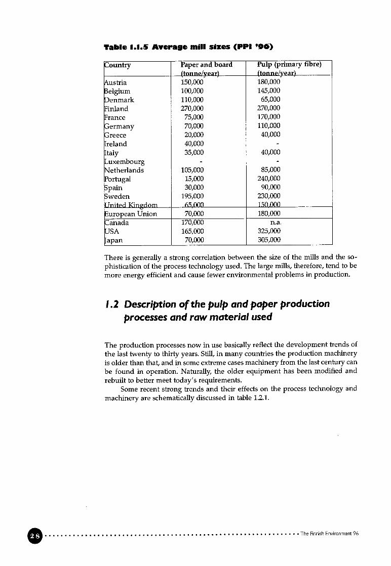
Table 1.1.5 Average miii sizes (PPI ‘96)
ountry Paper and board Pulp (primary fibre)(tonne/year) (ton n e/year)
ustria 150,000 180,0003elgium 100,000 145,000)enmark 110,000 65,000in1and 270,000 270,000rance 75,000 170,000ermany 70,000 110,000
reece 20,000 40,000reland 40,000 -
taly 35,000 40,000uxembourg - -
Jether1ands 105,000 85,0003ortugal 15,000 240,000;pain 30,000 90,000weden 195,000 230,000]nited Kingdom 65,000 150,000uropean Union 70,000 180,000:anada 170,000 n.a.JSA 165,000 325,000apan 70,000 305,000
There is generally a strong correlation between the size of the milis and the sophistication of the process technology used. The large mifis, therefore, tend to bemore energy efficient and cause fewer environmental problems in production.
1.2 Description of the pulp and paper productionprocesses and raw material used
The produclion processes now in use basically reflect the development trends ofthe last twenty to thirty years. Stiil, in many countries the production machineryis oider than that, and in some extreme cases machinery from the last century canbe found in operation. Naturally, the oider equipment has been modified andrebuilt to better meet today’s requirements.
Some recent strong trends and their effects on the process technology andmachinery are schematically discussed in table 1.2.1.
The Finnish Enronment 96

Table 1.2.1 ?rends affecting pulp and paper production
Frend s eguirements Solutinns Conseguences/Prereguisitesmproved images brightness bleaching of pulp - lower yield and higher
pollutant generation. multicolour. resolution
- higher energy consumption. combined advertising
- ower strength and stiffnessand packaging of chemical pulp
increased use of bright - less fibre in end product andadditives (fibres and higher solid waste generationpigments) in recycing
opacity additives - no change. maximum use of - increased use of externalmechanical pulps energy
smoothness, more refining of pulps - increased use of energygloss, surface increased use of surface - potentially higher pollutingstrength coatings loads
ower basis weight strength stronger chemical pulps - lower overail yield throughmore surface per more selecfive raw materialveight) usage
- more complex processesraw material stiffness increased use of refiner - increased use of externalefficiency mechanical pulps energyinvestment efficiencyreduced handling fees as above - as above
increased use of additives - higher pollution loadmultilayer forming - more complex machinery
‘&educed pollution increased yield - better raw-materialwater managementair reduced water improved dewatering - process water reusesoil and energy
- more efficient equipment andsolid waste build-up consumption processes
improved improved washing - use of new technologiesrecovery (enzymes)
- improved processmanagemnt
recycling of more efficient upgrading - increased generation of solidpaper and board of recycled paper and boarc waste
. more efficient deinkingincluding reuse of deinkingsludge
more efficient integrated and improved - use of advanced informationinternal treatment process management systemsof process water
- better training of persorinel
It can generally be said that the efforts to improve the technical performance offibres and additives tend to increase the generation of pollutants, and, therefore,more complex processes and management systems are needed to offset this effect.
TheFinnishErwironment96

The consequence is higher investment costs, which in hirn must be compensated
for by improved efficiency, such as a lower basis weight, and often by seeking
advantages from economy of scale.The basic principle for paper and board production is the same since in both
cases a siurry of fibres and additives is dewatered on a mesh wire. The “wire sec
tion” of the paper or board machine can be constructed in many different ways.
After the wire section, the saturated web is further dewatered by pressing. In
multilayer products two or more layers are formed on top of each other, as on
cylinder machines, or two or more webs are brought together, as on multi-wire
machines, before the pressing. The press section can also feature many different
constructional solutions. After the press section, the web is brought to its finaldryness of more than 90% by evaporafion in the so-called dryer section. Again,there are a number of technical solutions, but most frequently the temperature of
the web is raised by passing it over steel cylinders heated by the condensation of
steam on the inside of the cylinders. In the production of tissue the web is dried
by hot air and infra-red radiation, which are also used in the drying of coatings
applied to the surface of the paper or board.The productiviiy of the paper machine and the properties of the paper are
enhanced by additives, such as inorgamc fillers, retention aids, dry- and wet
strength resins as well as sizes in the furnish. The surface properties are mainly
modified by adding layers of coating to the paper or board either at the paper
machine itself or at off-machine coaters. After different kinds of finishing opera
tions, such as calendering for increased smoothness and gloss, the web is cut to
customer-size rolis or sheets and packed for shipping. The paper and board ma
nufacturing technoiogies are discussed in more detail in sections 3 and 4.
The overail environmental impact of the paper and board machine operation
is quite modest, aibeit there is some pollution as well as noise and steam piume
generation. As shown in table 1.2.1, the trends to upgrade the quality of the pro
ducts by increased refining of the fibres and the use of additives tend to increase
the pollutant load.The environmental impact of puiping can he serious if proper prevention
measures are not taken. Pulping can be described as walking a tightrope between
raw-material availability and properties at one end and the requirements for pa
per and board at the other. As is discussed in detail in section 3, chemical, heat and
mechamcal energy as well as any combination of these are used in the manufactu
ring of pulp. The differences bet-ween the main pulping processes are discussed in
table 1.2.2.Generaily, primary fibres are favoured in products requiring i) high clean
ness, like food packaging boards and special tissues, ii) extreme strength proper
ties, like sack and liner, iii) fauitless performance, like copy paper or iv) superior
appearance and performance, itke high quality printing papers, books and docu
ments to be kept in archives over a long period of time. Recycied fibres are mostiy
used in products with a short life span, like newspapers, cataiogues and inserts,
and also in low-cost, high-volume products, like toilet tissue, towels and materiais
for outer packaging.
O The Finnish Environment 96

H (D -n D D m 0 (D D ‘0 0’
Tab
le1.2
.1T
he
mai
npulp
ing
pro
cesses
inW
est
ern
Euro
pe
Mai
nca
tego
ryP
roce
ssR
awm
ater
ial
-Y
ield
Ene
rgy
Rem
arks
Che
mic
alpulp
Sul
phat
e(k
raft
)A
liw
ood
spec
ies
Low
(35-
55%
)M
oder
nm
ifis
The
dom
inat
ing
proc
ess
both
for
unbl
each
edan
dm
ost
non-
woo
dpr
oduc
ene
t(b
row
n)an
dbl
each
ed(w
hite
)gr
ades
.p
lan
tsen
ergy
Eff
icie
ntre
cove
ryof
proc
essi
ngch
emic
als
and
diss
oive
dm
ater
ial.
Net
ener
gypr
oduc
erfr
omburn
ing
the
diss
olve
dw
ood
mat
eria
l.C
ompi
exbl
each
proc
ess.
Hig
hfi
nal
brig
htne
ssat
tain
able
.S
uper
ior
stre
ngth
prop
erti
es.
Pol
luti
onpo
tent
ial
ishi
ghbut
isal
mos
tel
imin
ated
wit
hm
oder
nte
chno
logy
.S
oda
Mos
tly
hard
woo
d,L
ow(3
5-50
%)
Mod
ern
mill
sar
eIn
lim
ited
use
mai
nly
inde
velo
ping
coun
trie
s.an
nu
alcr
ops
self
-suf
fici
ent
Ver
ysi
mil
arto
kraf
tpu
lpin
g.
Sul
phit
eS
elec
ted
spec
ies
orL
ow(4
0-50
%)
Lim
ited
use
ofP
revi
ousl
yth
ed
om
inat
ing
proc
ess
beca
use
ave
ryco
mpl
exex
tern
alen
ergy
ofhi
ghin
itia
lbr
ight
ness
and
lim
ited
proc
ess
isre
quir
edco
mpe
titi
onfo
rth
epr
efer
red
raw
mat
eria
l.R
ecov
ery
ofpr
oces
sing
chem
icai
sis
effi
cien
tbut
com
plex
.G
ood
biea
chab
iity
,but
opac
ity
islo
w.
Str
engt
his
low
erco
mpa
red
wit
hkr
aft
pulp
s.A
irpo
llut
ion
thro
ugh
emis
sion
ofS
02
and
vola
tile
orga
nics
requ
ire
com
plex
frea
tmen
tfa
cilif
ies.
The
use
ofth
esu
lphi
tepr
oces
sha
sbe
enst
eadi
lyde
crea
sing
.
Sem
i-ch
emic
alN
SSC
(Neu
tral
Mos
tw
ood
spec
ies
Inte
rmed
iate
Lim
ited
use
ofL
imit
edst
reng
than
dop
tica
lpr
oper
ties
.pulp
sodi
umsu
lphi
te(7
5-85
%)
exte
rnal
ener
gyP
ollu
tion
load
high
,re
cove
ryis
com
plex
cook
ing)
and
expe
nsiv
e.N
one
wm
ills
are
bein
gbu
ilt
and
oper
atin
gon
esar
ebe
ing
mod
ifie
d.A
lso,
miil
sba
sed
onam
mon
ium
orm
agne
sium
base
are
inop
erat
ion.
(con
t.on
the
next
page
)

9 -1 CD 21 2 2 m 0 2 CD 2 0’
(tab
le1.
2.2
cont
.)M
ain
cate
gory
Pro
cess
Raw
mat
eria
lY
ield
Ene
rgv
Rem
arks
Sem
i-ch
emic
alS
oda
(gre
enM
ostly
hard
woo
dIn
term
edia
teL
imit
edor
noS
epar
ate
reco
very
isve
tyco
stly
but
pulp
(con
t.)li
quor
)sp
ecie
s(7
0-80
%)
use
ofex
tern
ala
favo
urab
leso
luti
onis
co-r
ecov
ery
ener
gyw
ith
akr
aft
puip
miii
.N
orm
ally
only
brow
npu
ips
for
pack
agin
ggr
ades
.P
ollu
tion
load
ishi
gh,
but
can
beco
ntro
iied
wit
hm
oder
nte
chno
logy
.M
echa
nica
ipu
lpG
roun
dwoo
dO
nly
sele
cted
woo
dH
igh
(95-
97%
)H
igh
use
ofO
nly
iow
dens
ity
soft
woo
dan
dha
rdw
ood
puip
spec
ies
exte
rnal
ener
gysp
ecie
s(s
pruc
e,as
pen)
are
norm
ally
used
.P
ine
can
bepr
oces
sed,
but
yiei
dspu
lpof
low
erqu
aiity
.T
hera
wm
ater
iai
has
tobe
inth
efo
rmof
logs
.In
itia
ibr
ight
ness
good
,bu
tii
mit
edbi
each
abili
ty.
Vet
ygo
odop
acity
,pa
per
form
atio
nan
dsu
rfac
epr
oper
ties
.W
ater
poil
utio
nis
mod
est,
but
biol
ogic
aitr
eatm
ent
ofw
aste
wat
eris
requ
ired
.A
irpo
liut
ion
depe
nds
onth
efu
elus
edin
the
gene
rati
onof
the
exte
rnai
ener
gy.
Ref
iner
As
abov
eH
igh
(92-
96%
)A
sab
ove
The
raw
mat
eria
iis
info
rmof
chip
s.m
echa
nica
ipu
ipS
tren
gth
isio
wer
than
that
ofch
emic
alpu
lps
but
bett
erth
anfo
rgr
ound
woo
d.O
ptic
aian
dsu
rfac
epr
oper
ties
siig
htly
infe
rior
togr
ound
woo
dpu
ip.
The
ener
gyus
age
ishi
gher
than
for
grou
ndw
ood,
but
ener
gyca
nbe
reco
vere
dfo
rus
ein
pape
ran
dbo
ard
prod
ucti
on.
Poi
iuti
onas
. abo
ve.
Rec
ycle
dfi
bre
Rec
ycle
dfi
bre
Sele
ctiv
eor
ali
Hig
hM
oder
ate
use
ofR
awm
ater
iai,
yiei
dan
den
ergy
usag
ear
eve
tyend
grad
esin
term
edia
teex
tern
aien
ergy
use
spec
ific
.(7
5-98
%)
Pol
lufi
onis
lim
ited
, but
the
gene
rati
onof
solid
was
tem
aybe
high
.C
hem
ical
trea
trne
ntof
was
tew
ater
ofte
nsu
ffic
ient
.D
eink
edpu
lpSe
lect
ive
As
abov
eA
sab
ove
The
dein
king
proc
ess
incr
ease
sen
ergy
usag
e.P
oliu
tion
load
incr
ease
sfr
orn
the
chem
icai
sus
edan
dso
me
diss
olvi
ngin
the
dein
king
proc
ess.
Was
tew
ater
norm
ally
requ
ires
bioi
ogic
altr
eatr
nent
.

2.1 PuIp and paper production
The pulp and paper industry is the industrial sector showing the largest net tradebalance in Finland. Further it is the heart of the so-called forest-cluster industrialsector, which is by far the most important part of the Finnish economy. The forestcluster includes, in addition, machinery for pulp, paper and board manufacturing, auxffiary equipment for the pulp and paper milis, chemicals, instrumentsand control equipment, and engineering work.
As aiready shown in section 1, Finland is the no. 2 producer of paper andboard in the EU and the no. 1 exporter of these products. It is also the no. 1 producer of pulp (primary fibre) and the no. 2 exporter of pulp. Table 2.1.1 shows theannual production of different pulp, paper and board grades in Finland.
‘rable 1.1.1 PuIp, paper and b.ard production in FnIand(Finnish Forest Indusfries Federation)
1994 1995(1,000 t) (1,000 t)
CHEMICAL PULP 5,844 5,782Unbleached kraft 687 680Bleached softwood kraft 2,831 2,928Bleached hardwood kraft 2,326 2,174
OTHER PULP 4,118 4,306( md. mechanical pulpand semi-chemical pulp)
PuIp, total 9,961 10,088
PAPER 8,546 8,595Newsprint 1,446 1,425Printing/writing 6,096 6,315
- Mechanical 4,073 4,385- Woodfree 2,024 1,929
Kraft paper 504 484Other paper 500 372
BOARD 2,363 2,346
Paper & board, total 10,909 10,942
The Finnish Environment 96
General description of the pulpand paper industry in Finland
For efficiency and environmental protection reasons, only the sulphate (kraft)pulping process is stiil used in Finland for the production of chemical pulp.
Almost 90% of the chemical pulp is bleached. Table 2.1.1 also shows the dominance of printing and writing paper grades. Finland is the worldwide technology leader and the no. 1 producer in Europe of the highest-quality magazinepaper grades (SC and LWC) as well as coated woodfree grades.
Despite a collection rate of 50-57% in Finland, the use of recycled fibre is lessthan 10% of the paper and board production because 90% of the products areexported. It makes poor sense in terms of environmental protection to try to increase the import of waste paper when there is an abundance of wood fibre available locally. The primary fibre m Finnish paper is needed to maintain sufficientquality in the recycled fibre stock in the EU countries importing paper from Finland.
The technology used in the Finnish pulp, paper and board industry isdescribed in more detail in section 3.
2.2 Finnish pulp and paper milis
The annual production of the mifis in 1995 as well as the number of fibre lines, andpaper and board machines is compiled in Appendix 3.
The Finnish pulp and paper industry is today dominated by three large ownership concentrations. The UPM-Kymmene and Metsäliitto (Forest owners)Groups, wbich are entirely privately owned, and the Enso Group, in wbich theGovernment holds a majority interest. The average capacity of the chemical pulping lines is 250,000 tonnes/year. The average capacity of the mechanical pulpinglines is 140,000 tonnes/year. The average capacity of the paper machines is 110,000tonnes/year and exduding the low-capacity tissue machines the average is 120,000tonnes/year. There are 13 machines with a capacity of over 200,000 tonnes/year.The average capacity of the board machines is 120,000 tonnes/year and there are 3machines with a capacity of over 200,000 tonnes/year.
Several of the most advanced mifis are described in detail in section 4.
2.3 Major process technology developments
There have been several major changes in the structure of and in the processtechnology used in the Finnish pulp and paper industry during the last fifty
years. Finland is a major producer of chemical and mechanical pulps. A dramaticincrease in the integrated production of pulp, paper and board has taken place,and today the Finnish pulp and paper industry’s exports of bleached kraft and
CTMP are less than 20% (in quantity) of the total pulp and paper exports. A simi
lar dramatic change has taken place in paper and board exports, where white(bleached) grades have almostfuily replaced brown (unbleached) grades with the
exception of some packaging materiais, such as liner and corrugating medium.
The above trends are the results of two major process technology changes within
chemical and mechanical pulping. In chemical pulping the conventional sulphite
pulping process has been completely replaced by the sulphate pulping method.
Both methods were invented in the second half of the l9th century. The sulphite
method was based on using calcium sulphite as the cooking chemical. The low
O The Finneh Environment 96

cooking pH of 1 to 2 produced pulps of high initial brightness, 55 to 70% ISO, fromspruce, birch and aspen. Pine could not be processed successfully because of thehigh rosin content. The good brightness made sulphite pulps the natural choicefor the production of printing and writing papers and of newsprint together withstone groundwood pulp, because sulphate pulps were very dark (brown). ThepH of sulphate cooking is 12 to 13 and the high pH causes discoloration of thewood. As long as there were no suitable bleaching methods, calcium sulphite mifiswere built to satisfy the need for bright paper-making fibres. The biggest handicap of calcium sulphite pulping is that there is no economical way of recoveringthe cooking chemicals for reuse, and for a period of time the spent cooking liquorwas discharged directly into the recipient. The last calcium sulphite mills in operation, however, had installed evaporation and burning to recover at least theheat in the dissolved organics, but the S02 generated in the burning was releasedinto the air. On the other hand, very early on there had been methods developedfor the recovery of the cooking chemicals in the sulphate process.
The competitive situation between the two pulping processes changed firstof ali with the invention of bleaching with chlorine gas, wbich made the use ofsulphate fibres possible in information paper grades. This breakthrough was thenfur-ther strengthened with the development of chlorine dioxide bleaching, whichmade it possible to bleach sulphate pulps to a very high final brightness, and thepulp could be used in the most demanding paper grades. At the same time theproblems related to the high content of extractives in hardwood pulp, whichwere harmful in the paper-making process, were solved, and birch kraft pulp became the dominant fibre source for time paper production. The second major changein the competitive situation came about when the environmental protection situa-tion forced the sulphite milis to opt for chemical recovery. In Finland costanalyses comparing the switch to sodium- or magnesium-based cooking and installing complex recovery systems always came out in favour of switching to sulphatepulping. Two very important factors favouring the sulphate process are the possibility to pulp ail wood species and the superior strength properties of the fibres.The last sulphite miil in operation, actually with a sodium base and a recoverysystem, was closed down in 1991. Today only one alkaline sulphite (SAP) line,wbich shares with chemical recovery with a sulphate mii, is in operation. Onesemi-chemical pulping line based on ammonium sulphite and another based onsodium sulphite produce corrugating medium.
The recent discussion about the discharges of chlorinated organic compounds(AOX) from the bleaching of chemical pulps appeared for a while to give thesulphite process a compefifive edge again, but within a relatively short time spanchlorine gas free (ECF) and totally chlorine free (TCF) bleaching sequences weredeveloped for sulphate pulping, eliminating the differences between the processes.
During the last twenty years the groundwood pulping processes (SGW, PGW,PGW-S) have fallen from being the only mechamcal pulping processes into second position behind refiner-based mechanical pulping (TMP). Here the two mainreasons are improved strength properties and greater raw-material versatility. Thehigher electrical energy consumption in refiner pulping has been compensatedfor by efficient heat recovery (25-50%). The recovered heat is normally used fordrying the paper.
The Finrish Enronment 96

Technical description of the most
important pulp, paper and board
manufacturin9 processes In
Finland..............................................
3.1 General
In pulp production, pulping, a siurry of individual fibres in water, is producedfrom a multitude of raw materiais holding suitable fibres i.e. wood, straws, leaves,
waste paper. In paper and board manufacturing a web is formed by dewatering asiurry of fibre on a mesh wire. The siurry can hold fibres ftom many differentpulping processes and raw materiais as well as some process or product- enhancing additives and mineral pigments.
The different types of pulps are named after the predominant form of ener
gy, chemical or mechanical, that is used to separate the fibres and/or by the rawmaterial, e.g. recycled fibre, deinked pulp, hardwood pulp. In chemical pulpingthe fibres are separated by dissolving the substance, ligriin, holding them together. In mechanical pulping the fibres are forced apart by attrition and in semichemical pu1pmg there is a combination of both chemical and mechanical action.In the pulping of waste paper the use of chemicals and mechanical energy is, bycomparison, low.
The dissolving action of the chemicals wffl naturally cause a yield loss. Thedissolved substances, as well as the used chemicals, are mostly detrimental to the
subsequent use of the fibres and need to be removed from the pulp, or the pulphas to be washed. The heat value of the dissolved organic material is normally
recovered through combustion and the chemicals regenerated. Modern chemicalpulping mifis are often self-sufficient with regard to energy. In mechanical pulping the yield loss is quite small and the energy needed to perform the mechanicalwork, electricity, is brought into the plant. In recycled-fibre pulpmg both freshchemicals and energy have to be brought into the plant. As the waste paper contains various amounts of non-fibrous material, like ffflers and pigments, which are
not recovered today, the yield in waste-paper pulping is between 60% and >90%and the generation of solid waste can, accordingly, be high.
Different pulps are mixed together according to the requirements of the end
product. The pulps are screened to remove impurities and the fibres bleached
with different bleaching chemicals to increase their whiteness. Both processes tendto reduce the yield as both suspended and dissolved orgariic material is removed
from the pulps. This yield loss is a major source of water pollution if the substan
ces are not separated from the water and properly disposed of.In kraft pulping the recovery of process chemicals and in mechanical pulp
ing the use of external energy are sources of ah pollution.The final environmental impact of any type of pulping is strictly dependent
on the combined success of internal recovery at the plant and the efficiency of the
external treatment.
O The Finnish Environment 96
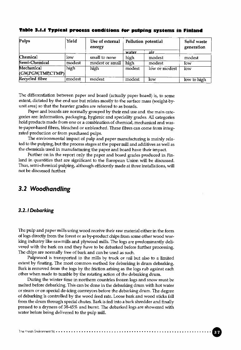
Tahle 3.1.1 Typical process conditions for pulping systems in Finland
‘ulps Yield Use of external Pollution potential Solid wasteenergy generation
water airheniical low small to none high modest modestemi-Chemical modest modest or small high modest low
vlechanical high high modest low or modest lowGW,PGW,TMP,CTMP)ecyc1ed fibre modest modest modest low low to high
The diiferentiation between paper and board (actually paper board) is, to someextent, dictated by the end use but relates mostly to the surface mass (weight-byunit area) so that the heavier grades are referred to as boards.
Paper and boards are normally grouped by their end use and the main categories are: information, packaging, hygienic and speciality grades. Ali categorieshold products made from one or a combination of chemicai, mechanical and waste-paper-based fibres, bleached or unbleached. These fibres can come from integrated production or ftom purchased pulps.
The environmental impact of pulp and paper manufacturing is mainly related to the pulping, but the process stages at the paper mifi and additives as well asthe chemicals used in manufacturing the paper and board have their impact.
Further on in the report only the paper and board grades produced in Finland in quantities that are significant to the European Union wffl be discussed.Thus, semi-chemical pulping, although efficiently made at three installations, wiIlnot be discussed further.
3.2 Woodhandling
3.2.! Debarking
The pulp and paper milis using wood receive their raw material either in the formof logs directly from the forest or as by-product chips from some other wood working industry like sawmffls and plywood mifis. The logs are predominantly delivered with the bark on and they have to be debarked before further processing.The chips are normally free of bark and can be used as such.
Pulpwood is transported to the mills by truck or rail but also to a limitedextent by floating. The most common method for debarking is drum debarking.Bark is removed from the logs by the friction arising as the logs rub against eachother when made to tumble by the rotating action of the debarking drum.
During the winter time in northern countries frozen logs and snow must bemelted before debarking. This can be done in the debarking drum with hot wateror steam or on special de-icing conveyors before the debarking drum. The degreeof debarking is controlled by the wood feed rate. Loose bark and wood sticks failfrom the drum through special chutes. Bark is fed into a bark shredder and finallypressed to a dryness of 38-45% and burnt. The debarked logs are showered withwater before being delivered to the pulp mifi.
The Finnish Environment 96
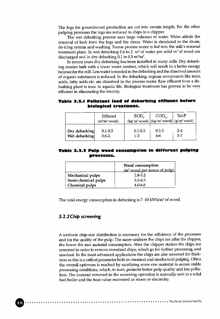
The logs for groundwood production are cut into certain length. For the other
pulping processes the logs are reduced to chips in a chipper.The wet debarking process uses large volumes of water. Water affects the
removal of bark from the logs and the drum. Water is circulated in the drum,
de-icing system and washing. Excess process water is fed into the mill’s external
treatment plant. In wet debarking 0.6 to 2 m3 of water per solid m3 of wood are
discharged and in dry debarking 0.1 to 0.5 m3/m3.In recent years dry debarking has been installed in many milis. Dry debark
ing creates bark with a Iower water content, which wil resuit in a better energy
balance for the miii. Less water is needed in the debarking and the dissolved amount
of organic substances is reduced. In the debarking, organic compounds like resin
acids, fatty acids etc. are dissolved in the process water. Raw effluent from a de
barking plant is toxic to aquatic life. Biological treatment has proven to be very
efficient in eliminating the toxicity.
Table 3.1.1 Pollutant Ioad of debarking effluent beforebioIoicaI treatment.
Effluent BOD7 CODCr Tot-P(m3/m3wood) (kg/ m’ wood) (kg/ m3 wood) (g/ m3 wood)
Dry debarking 0.1-0.5 0.1-0.5 0.2-2 2-4Wet debarking 0.6-2 1-3 4-6 5-7
Tablc 3.1.2 PuIp wood consumption in differen pulpin9processes.
Wood consuniption(m3 wood uer uu1v’
Mechanical pulps 2.8-3.2Semi-chemical pulps 3.5-4.5Chemical pulps 4.0-6.6
The total energy consumption in debarking is 7-10 kWh/m3of wood.
3.2.2 Chip screening
A uniform chip-size distribution is necessary for the efficiency of the processes
and for the quality of the pulp. The more uniform the chips are after the chipper,
the lower the raw material consumption. After the chipper station the chips are
screened in order to remove oversized chips, which go for further processing, and
sawdust. In the most advanced applications the chips are also screened for thick
ness as tMs is a critical parameter both in chemical and mechanical pulping. Often
the overali optimum is reached by sacrificing some raw material to secure stable
processing conditions, which, in turn, promote better pulp quality and less pollu
tion. The material removed in the screenirLg operation is normally sent to a solid
fuel boiler and the heat value recovered as steam or electricity.
: The Finnish Environment 96

Fresh woter
3.3 Chemical pulp
In the chemical pulping process the fibres are liberated from the wood matrix asthe lignin is removed by dissolving in the cooking chemical solution at a hightemperature. Part of the hemicellulose is dissolved as well in the cooking.
Chemical pulp is manufactured by two main pulping processes, the sulphiteprocess and the sulphate or kraft pulping process. In the sulphite process thecooking chemical is bisulphite or sulphite, and in the kraft pulp process the cooking chemicals are sodium hydroxide and sodium sulphide.
Today kraft pulping is the dominant process throughout the world for manufacturing chemical pulp. In Finland the kraft process has, in a relatively shorttime, taken over completely. In 1965 there were 19 sulphite pulp mills and 16 kraftpulp milis. OnIy3 sulphite pulp milis were left m 1985 and in 1991 the last conventional sulphite pulp miii was shut.
The main reasons for the kraft pulp process replacing the sulphite processare that
- ail wood species can be processed- kraft pulp has superior strength properties compared with sulphite pulp- the recovery of chemicals and energy is efficient.
3.3.! The kraft pulping process
A kraft pulp miii can be divided into three main parts: chemical defibration (delig—nification) with an almost completely closed chemical and energy recovery sys
The Finnish Enironment 96
Figure 3.2. 1 Wood debarking

tem, bleaching with an open water system and the process external waste watertreatment system. Another more conventional division is the fibre line, recoverysystem and external waste water treatment.
The part of the fibre line with an almost totally closed water system includescooking, pulp washing and screening and, in most mifis, oxygen delignification aswell (figure 13.1). The process liquid is led counter-current to the pulp flow. Thespent liquor (black liquor) is removed in the first pulp washing stage, concentrated and burnt. The inorganic chemicals in the black liquor are recovered aftercombustion, regenerated into cooking chemicals and returned to cooking. Theenergy produced in the combustion of the organic material dissolved in the delignification is used in the process as heat and electrical energy. In a kraft pulp miiiabout half of the raw material is converted into energy. In a modern kraft pulpmiii more energy is produced than is consumed.
If pulp with a high brightness is being produced, the pulp has to be bleachedafter cooking and washing. The filtrates from bleaching are discharged ftom theprocess into the external waste water treatment. Extensive research and development work on returning the bleaching fiitrates to the chemical recovery systemhas been going on ali over the world since the 1970s. The implementation of total
ly chlorrne free bleaching technology makes it possible to recycle the bleachingplant ifitrates without the nsk of corrosion and process upsets.
Figure 3.3. 1 Sources of discharges into water from a kraft pulp miii
Delignification, washing and screening
In the kraft process the fibres are liberated in the cooking plant by dissolving the
lignin and part of the hemicellulose in the cooking chemical solution (white li
quor), which contains sodium hydroxide and sodium sulphide as active chemi
cals. The cooking process can be performed either in batch digesters or in a confi
nuous digester. The chips are pre-heated by steam before entering the continuous
digester in order to remove air, which interferes with the impregnation. After en
tering the digester, the chips are iinpregnated with cooking liquor. After impreg
nation the temperature is raised to 165-175° C.
The Finnish Environment 96
Wood
[cQI 1Fresh water (prepcrationl
Organicsubstances
Organc substansesNutrients
Tanks
SpiIIsInorgonic substonces

The pulp coming from the cooking contains both fibres and spent cooking liquor(black liquor). About half of the wood is dissolved in the cooking. Consequentlythe black liquor contains inorganic chemicals and a large amount of organic substances. The black liquor is removed from the pulp in the subsequent washingand led to the chemical recovery system, where the cooking chemicals and energyare recovered.
If the objective is to produce pulp with a high brightness, the residual ligninhas to be removed almost completely m a bleaching plant. The amount of residualligrnn is usually reported as Kappa number. A high Kappa indicates high residuallignin in the pulp. After cooking, a typical Kappa level has been 30-34 for softwood and 18-22 for hardwood. If the Kappa is lowered further from the leveismentioned in conventional batch or continuous cooking processes, the yield andthe pulp strength properties are drastically lowered.
Several cooking modification methods have been developed with the aim ofremoving more ligriin from the wood without reducing the yield during cooking.The Kappa from the cooking of softwood can be reduced to a level of 15-25 throughextended delignification, while the yield and strength properties are stifi maintained. This means that 25-50% less lignin is left in the pulp compared with pulpthat has a Kappa of 32. The requirements for bleaching chemicals are, therefore,reduced and the effluent discharges from the bleaching plant are decreased. Comparable Kappa reductions can he achieved in the cooking of hardwood (figure3.3.2).
35
30
25
20z
16
10—*—SW. to bIeaiing
5 —&—SW, atter 02-dehgn.
0to to 0 to -
0
VEAR
Figure 3.3.2 Kappa trends in Finnish kraft pulp milis.
Extended cooking affects several elements in the kraft process:- the consumption of active alkali (NaOH + Na2S) increases- the amount of dissolved substances going to the recovery increases- heat generation in the recovery boiler increases- the demand for bleaching chemicals decreases- there is a lower pollutant load m the waste water from bleaching- in modified batch cooking the energy consumption and blow steam amount
decrease in the cooking, but the steam consumption in the evaporation of theblack Iiquor may increase.
The impact of extended cooking on production is very site specific. If therecovery system is a production bottleneck at a miil, there is a risk of a loss inproduction when the conversion is made to extended delignification.
The Finnish Environment 96
—
—O—HW. after coo}dng
—W— HW, to bleaching
——HW, after 02-dellgn.
YEAR
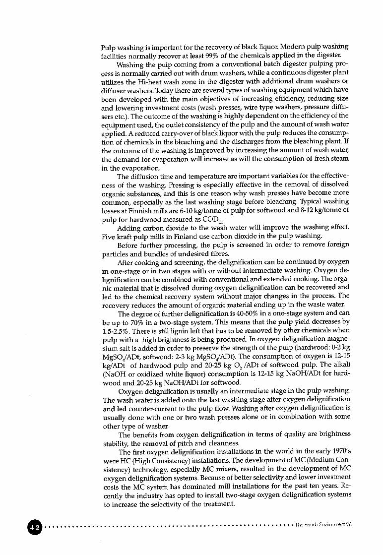
Pulp washing is important for the recovery of black liquor. Modern pulp washing
facilities normally recover at Ieast 99% of the chemicals applied in the digester.
Washing the pulp coming from a conventional batch digester pulping pro
cess is normally carned out with drum washers, while a continuous digester plant
utilizes the Hi-heat wash zone m the digester with additional drum washers or
diffuser washers. Today there are several types of washing equipment which have
been developed with the main objecfives of increasing efficiency, reducing size
and lowering investment costs (wash presses, wire type washers, pressure diffu
sers etc.). The outcome of the washing is highly dependent on the efficiency of the
equipment used, the outlet consistency of the pulp and the amount of wash water
applied. A reduced carry-over of black liquor with the pulp reduces the consump
tion of chemicals in the bleaching and the discharges from the bleaching plant. If
the outcome of the washing is improved by increasing the amount of wash water,
the demand for evaporation wffl increase as wffl the consumption of fresh steam
in the evaporation.The diffusion time and temperature are important variabies for the effective
ness of the washing. Pressing is especially effective in the removal of dissolved
organic substances, and this is one reason why wash presses have become more
common, especially as the last washing stage before bleaching. Typical washing
losses at Finnish milis are 6-10 kg/tonne of pulp for softwood and 8-12 kg/tonne of
pulp for hardwood measured as CODCrOAdding carbon dioxide to the wash water will improve the washing effect.
Five kraft pulp milis in Finland use carbon dioxide in the pulp washing.
Before further processing, the pulp is screened in order to remove foreign
particles and bundies of undesired fibres.After cooking and screening, the delignificafion can be continued by oxygen
in one-stage or in two stages with or without intermediate washing. Oxygen de
lignification can be combined with conventional and extended cooking. The orga
nic material that is dissolved during oxygen delignification can be recovered and
led to the chemical recovery system without major changes in the process. The
recovery reduces the amount of organic material ending up in the waste water.
The degree of further deligriification is 40-50% in a one-stage system and can
be up to 70% in a two-stage system. This means that the pulp yield decreases by
1.5-2.5%. There is stifi lignin left that has to be removed by other chemicals when
pulp with a high brightness is being produced. In oxygen delignification magne
sium salt is added in order to preserve the strength of the pulp (hardwood: 0-2 kg
MgSOJADt, softwood: 2-3 kg MgSOJADt). The consumption of oxygen is 12-15
kg/ADt of hardwood pulp and 20-25 kg 02 /ADt of softwood pulp. The alkali
(NaOH or oxidized white Iiquor) consumpfion is 12-15 kg NaOH/ADt for hard
wood and 20-25 kg NaOH/ADt for softwood.Oxygen delignification is usually an intermediate stage in the pulp wasbing.
The wash water is added onto the last washing stage after oxygen delignification
and led counter-current to the pulp flow. Washing after oxygen delignification is
usually done with one or two wash presses alone or in combination with some
other type of washer.The benefits ftom oxygen delignification in terms of quality are brightness
stability, the removal of pitch and cleanness.The first oxygen delignification installations in the world in the early 1970’s
were HC (High Consistency) installations. The development of MC (Medium Con
sistency) technology, especially MC mixers, resulted in the development of MC
oxygen delignification systems. Because of better selectivity and lower investment
costs the MC system has dominated mifi installations for the past ten years. Re
cently the industry has opted to install two-stage oxygen delignification systems
to increase the selectivity of the treatment.
O The Finnish Environment 96

The first installation in Finland was started up in 1988, and by the end of 1995 80%of kraft pulp was delignified with oxygen. There are four two-stage systems inoperation (1995). The oxygen is mainly purchased, but during 1996 two on-siteplants are coming into operation.
Like extended cooking, oxygen delignification affects the chemical recoverysystem, the mill’s energy balance and operating costs. There can be a slight mcrease in the generation of steam in the recovery boiler, but steam consumptionwffl increase because of the increased demand for evaporation and the oxygenstage. The consumption of electrical energy wffl increase as wffl fuel consumptionin the ilme kUn.
The reduction of the Kappa of unbleached pulp (brown stock), whether it isachieved through extended digester delignification, oxygen delignification or someother method, wffl reduce the load of bleaching-plant pollutants that enter theexternal effluent treatment system.
BleachingThe purpose of pulp bleaching is to remove the remaining lignin and impu
rities in the pulp and thus obtain certain pulp quality criteria with respect to brightness, brightness stabffit cleanness and strength. The brightness of unbleachedkraft pulp is rather low, below 30% ISO. Fuily bleached pulp has a brightness of88% ISO or higher.
Cooking and oxygen delignification cannot remove ail the lignm without adrastic loss of yield and strength. The bleaching of chemical pulps is carried out inseveral stages, usually four to five. The most commonly used chemicals are chlorine dioxide, oxygen, ozone and peroxide. Chlorine has not been used as a pulpbleaching chemical in Finland since 1993, and the use of hypochlorite ceasedbefore tilat. Smail amounts of chlorine are formed as a by-product in most of thechlorine dioxide generation systems used, and a part of this chlorine will bepresent when chlorine dioxide is used m bleaching.
Today ozone has been introduced as a very reactive bleaching agent. CMorine dioxide, oxygen and hydrogen peroxide are less reactive. Because of the different reaction mechanisms different types of bleaching chemicals are utilized in ableaching sequence. Acid and alkaline stages are used to complement each other.
Chlonne dioxide and ozone have to be produced on site. Peroxide, oxygenand alkali are delivered to the mifis. The production of bleaching chemicals on siteis discussed under the heading “Generation of bleaching chemicals on site”.
The two main types of bleaching methods are the ECF (elemental chlorinefree) bleaching and the TCF (totally chlorine free) bleaching. The chemicals usedin ECF bleaching are chlorine dioxide, alkali (NaOH or oxidized white liquor)used for the extraction of dissolved ligrnn, peroxide as weil as oxygen for the reinforcement of the extraction stages. The bleaching chemicals used in TCF bleaching are oxygen, ozone and peroxide. Alkali is used for extraction. The selecfivity isbetter in bleaching than in cooking and oxygen delignification (figure 3.3.3). Chlorine dioxide and chlorine are the most selective bleaching agents. Selectivity isimportant as far as the total yield and pulp quality are concerned because highselectivity means that the bleaching chemical is primarily reacting wmth the lignin.
The Finnish Enironment 96 O
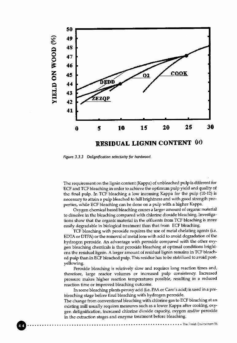
50
490”
046
Z0
44
43
42
41
o 30
RESIDUAL LIGNIN CONTENT 04)
Figure 3.3.3 Delignification selectivity for hardwood.
The requirement on the lignin content (Kappa) of unbleached pulp is different forECF and TCF bleaching in order to achieve the optimum pulp yield and quality ofthe final pulp. In TCF bleaching a low incoming Kappa for the pulp (10-12) isnecessary to attain a pulp bleached to fuil brightness and with good strength properties, while ECF bleaching can be done on a pulp with a higher Kappa.
Oxygen chemical based bleaching causes a larger amount of orgamc materialto dissolve in the bleaching compared with chlorine dioxide bleaching. Investigations show that the organic material in the effluents from TCF bleaching is moreeasily degradable in biological treatment than that from ECF bleaching.
TCF bleaching with peroxide requires the use of metal chelating agents (i.e.EDTA or DTPA) or the removal of metal ions with acid to avoid degradation of thehydrogen peroxide. Ari advantage with peroxide compared with the other oxygen bleaching chemicals is that peroxide bleaching at optimal conditions brightens the residual lignin. A larger amount of residual lignin remains in TCF bleached pulp than in ECF bleached pulp. This residue has to be stabffized to avoid postyellowing.
Peroxide bleaching is relatively slow and requires Iong reaction times and,therefore, large reactor volumes or increased pulp consistency. Increased
pressure makes higher reaction temperatures possible, resulting in a reduced
reaction time or improved bleaching outcome.In some bleaching plants peroxy acid (i.e. PAA or Caro’s acid) is used in a pre
bleaching stage before final bleaching with hydrogen peroxide.The change from conventional bleaching with chlorine gas to ECF bleaching at an
existing mifi usually requires measures such as a lower Kappa after cooking, oxy
gen delignification, increased chlorine dioxide capacity, oxygen and/or peroxide
in the extraction stages and enzyme freatment before bleaching.
The Rnnsh Enironment 96
5 10 15 20 25

The change from ECF to TCF bleaching affects the material and energy balancesof the whole miii. The consumption of wood and cooking chemicals increases,and the load of dry matter going to the recovery boiler increases due to extendeddeligriification. In particular, the consumption of electrical energy increases whenthe change is made ftom ECF bleaching to TCF bleaching with ozone. Ozone hasto be generated on site. In TCF bleaching the generation of ozone consumes about100 kWh/ADt of pulp and the overail more complex process another 100 kWh/ADtof pulp.
In 1995 ail mifis producing bleach kraft pulp in Finland used ECF bleaching.Seven mifis can produce TCF pulp. Two of these mifis produce TCF pulp usingozone. In 1995 the main part of the bleached pulp was ECF pulp (> 90%) and lessthan 10% was TCF pulp (hardwood and softwood). A new Finnish pulp miii startedup in the spring of 1996 with a production capacity of 500,000 t/a TCF bleachedsoftwood kraft pulp. The bleaching technology is based on MC ozone bleaching.The new kraft pulp miii is described in more detail in section 6.
Applications with enzyme treatment before bleaching have been in use inFinland since 1991. Enzyme treatment can be combined with different bleachingsequences. The benefits obtained from enzymes are dependent on the bleachingsequence used as weil as the residual lignin content of the pulp. Initially, enzymeswere used in chlorine bleaching in order to reduce the amount of chlorine. Lateron, enzyme treatment was combined with various TCF bleaching sequences toimprove the brightiess of the pulp or to decrease the consumption of bleachingchemicals. In bleaching with peroxide the brightness can he improved by 2-4 ISOunits. The use of enzymes causes a smafl Ioss of yield.
Chemical and energy recovery systemThe recovery system in a kraft pulp miii has three functions:
- the recovery of the morganic pulping chemicals- the destruction of the dissolved organic material and recovery of the energy
content as process steam and electrical power- the recovery of valuable organic by-products (e.g. tail oil).The fuel value of the recoverable black Iiquor is normally enough to make
the kraft pulp mifis more than self-sufficient in heat and electrical energy Organicby-products play a limited economic role in most kraft pulp mills.
The main process units in the chemical recovery system are the evaporationof the black liquor, combustion and causticizing, including ilme regeneration (figure 3.3.1).
Weak black Iiquor from the pulp washers normally has a dissolved solidscontent of 14-18%. This has to be increased considerably before the liquor can beburnt in the recovery boiler. The Iiquor is concentrated in a multi-effect evaporation plant to a dry-solids content of 65-75%.
The viscosity of the black liquor increases drastically during evaporation whenthe dry-solids content increases. When the dry-solids content is high, the liquorviscosity becomes too high for pumping. At atmospheric pressure the upper limitis about 72-74% DS. To eliminate this probiem two different prhiciples are used:
- pressurizing the liquor, which allows the temperature of the liquor to behigher, which, in turn, lowers the viscosity
- changing the liquor viscosity by altering the liquor rheology through a thermal depolymerization process.
The evaporation of the liquor can be extended to concentrations of over 80%by using heat treatment on the strong black liquor and pressurized evaporation.Heat treatment has been instailed in some Finnish milis.
The Finnish Environment 96

In heat treatment some of the combustible material separates as non-condensable
gases whlch contain TRS (total reduced sulphur). These gases are collected and
burnt together with other malodorous gases.Foul condensates (containing TRS and volatile organic compounds) from the
black liquor evaporation and the cooking plant are treated in a stripper columnthat is normally integrated with the black liquor evaporation by using secondary
steam (or primary steam). The condensate stripping makes it possible to reuse thecondensate in washing the unbleached pulp and in the causticizing plant.
The concentrated black liquor is burnt in the recovery boiler to recover thesodium and sulphur content in a suitable chemical form to regenerate the pulpmgchemicals and recover energy from the flue gases.
The increase in the dry-solids content of the black liquor from 65-70% to
80-85% changes the material and energy balances and the burnrng conditions inthe recovery boiler. The flue gas flow decreases as less water enters the furnace.By increasing the dry-solids content to e.g. over 80% an increase m production orextended delignification with more a effident recovery of the black liquor can bepossible in a mifi where the recovery boiler is the production capacity bottleneck.The combustion temperature increases because of the lower water content. Thehigher temperature causes more sodium (Na) to be vaporized, and, as vaporizedsodium reacts with sulphur, this results in a reduction of the sulphur emissionsfrom the recovery boiler to almost zero. TRS eniissions from the recovery boilerare well below 5 ppm. Steam generation wffl also increase.
The smelt leaving the recovery boiler is dissolved in water or weak whiteliquor to produce “green liquor”. The main components of green liquor are so
dium sulphide and sodium carbonate. The green liquor is clanfied and caustici
zed with ilme to produce white liquor for pulping. In causticizing Na2CO3is converted to NaOH. Ash residuals and other impurities are removed from the pro
cess (green liquor dregs). The ilme mud (CaCO3) formed in the causticizing is
separated from the white liquor, washed and calcined in a ilme kun to regeneratethe ilme. The ilme mud burning is a high-temperature, endothermic reaction, so it
is necessary to use external fuel.In the handling and burning of black liquor that has a high sulphur content,
sulphur is emitted into the air as sulphur dioxide and malodorous gases. The malodorous gases contain reduced sulphur compounds (hydrogen sulphide, methylmercapthane, dimethylsulphide and dimethyldisulphide). The non-condensiblegases from the cooking plant and the stripper gases from the steam stripping of
foul condensates ftom the evaporation plant usually contain 1-2.5 kg S/ADt.The strong malodorous gases are collected and generally burnt in a separate
burner or in the lime kiln. The practice of burning strong malodorous gases in the
lime kiln is today less favoured because it might disturb the operation of the ilmekiln. The flue gases are in most cases treated in a scrubber, and the scrubber wateris led back to the chemical recovery system. The kraft pulp mills in Finland also
coilect weak malodorous gases to a varying extent. Weak gases are emitted fromchip pre-steaming, screening, pulp washing, the smelt dissolver and tank ventila
tions etc. Weak malodorous gases contain 0.2-0.5 kg S/ADt. Weak malodorous
gases are burnt in the ilme kUn or the recovery boiler, or they are treated in a
scrubber.
O The Finnish Environrnent 96

Generation of bleaching chemicals on site
Chlorine dioxide
Chlorine dioxide can only be produced as a weak gas on site and it has to be storedas a water solufion. The solubility in water is relatively ow (8-10 g C1OJ1). A number of processes for the on-site production of chlorine dioxide have been developed, ali based on the reduction of sodium chlorate. The generation of sodium chlorate can be integrated with the C102 manufacturing on site, but most kraft pulpmilis in Finland purchase the sodium chlorate.
The overail chemical reaction for the generation of chlorine dioxide isChlorate + Reducing agent + Acid -> Chlorine dioxide + By-productsThe reducing agent and acid used have a substantial impact on the amounts
of by-product chlorine, sodium and sulphur that are produced.The overafi process flowsheet is shown in figure 3.3.4.The chlorine dioxide generation processes (chemical reactions and balances)
in use in the Fhmish kraft pulp industry are shown m appendix 2.Air emissions are usually modest, including some losses of chLorine or chlori
ne dioxide from storage tanks and scrubbers.
NaC1O3
Reducing agent(S02,NaC1, CH3OH)
Acid(H,S04,HC1)
Utilities
_____________
(water, steam, power, air)
ChlorineDioxideGenerator
C1O, solution
By-product Cl,
By-product S and Na(acid solution or crvstal)
Discharges, emissions(water. air)
Figure 3.3.4 Overali process flowsheet for chlorine dioxide generatiorl.
If aH the by-product sodium and sulphur could be taken into the kraft pulp miii asmake-up chemicals, there would be very little or no effluent, but if the sodium orsulphur by-product production is in excess of the mffl’s make-up requirements,these by-products have to be removed from the process. The by-product sodiumand sulphur amounts produced in different chlorine dioxide generation processes are shown in the following table.
Table 3.3.1 By-product sodium and sulphur generationin some cfllorine dioxide processes (based onCI0 use of 00 k5 act. CI/ADC .1 pulp).
1O2 process MATHIESON(kg/ADt) 17.1
Na (kg/ADt) 8.6
R3 R3H R5 K6 R7 R812.1 6.0 0 0 8.6 7.317.0 8.4 8.6 0 12.5 7.8
In the R6 process NaC1O3manufacturing is integrated with the R5 process.
The Finnish Enironment 96 O

Ozone generation
Because of its poor stability and the low concentration of ozone in the gas, ozone
is produced from oxygen or dry air on site. The ozonator consists of an alternatingvoltage (10,000-20,000 V) applied across two electrodes separated by a dielectric
gas gap. The ozone yield and overali power efficiency are functions of the oxygenconcentration of the feed gas, temperature, pressure, peak voltage and frequency.Literature data indicates that the power demand is 10-12.5 kWh/kg 03 at concentrations of 7-10%.
Because of the low concentration of 03 in the exit gas ftom the ozonator, thequantity of unreacted oxygen is stiil very large (ozone dosage: 7kg OJADt of pulpwffl give 70-120 kg OJADt of pulp). This quantity is too large to be fully utffized hia kraft pulp mifi (in e.g. oxygen deligriification, the oxidation of white liquor or foruse in the activated sludge treatment). The oxygen gas that is not utilized in theseprocess units is, therefore, returned to the ozonator.
3.3.2Effects of process solutions in the kraft pulping process
The impact of the different process solutions discussed in section 3.3.1 on discharges into the recipient, chemical and energy consumption, and the process andmifi performance are summarized in the following table.
O The Finnish Environment 96

•1 D D :3-
m D 0 D 3 CD 0
Table
3.3
.1Im
pac(
of
pr.
cess
solu
tions.
(‘+
‘=
incre
ase,
‘-‘
=decre
ase,
‘nc’
=no
ch
an
e)
Pro
cess
measu
reD
iseh
arges
and
emis
sions
fto
mth
eC
hem
ical
con
sum
pti
on
Ener
gy
co
nsu
mp
tio
nP
roce
ss,
pro
cess
mii
iper
form
ance
Wat
erA
irS
oli
dw
aste
Ex
ten
ded
coo
kin
g-
conti
nuou
s(c
)/
bat
ch(b
)-
CO
D/T
OC
+sm
eli
+co
okin
g(+
)co
ok
ing
(c)
+en
ergy
gen
erat
ion
-A
OX
-bie
achin
g-
coo
kin
g(b
)+
finaI
pu
lpyie
ld+
lim
ed
em
an
d(+
)ev
apora
tion
(+)
lim
ekil
nIm
pro
ved
wash
ing
-w
ash
pre
ss-
CO
D/T
OC
-bie
achin
g+
was
hin
g(e
i)-
cookin
g*)
alt.
dec
reas
esw
ash
wat
er-C
02
wash
ing
-*)
-bie
achin
gco
nsu
mp
tio
nan
d-
cookin
gev
apora
tion
dem
and
02
deli
gnif
icati
on
-+
02-s
tage
+0
2-s
tag
e(e
i+st
eam
)(+
ener
gy
gen
erat
ion)
-ble
achin
g+
whit
eli
q.o
xid
atio
n+
cau
stic
.&
iim
ekun
Ozo
ne
stag
ean
dre
cover
yof
fiit
rate
-+
03-s
tage
+0
3-s
tag
e,-
finai
bie
achin
g+
03
gen
erat
ion
-bie
achin
gE
CF
->T
CF
CO
D/T
OC
-p
ulp
yie
id(a
tsa
me
inco
min
gK
app
a)-
AO
X
-N
(chel
at.
agen
t)E
nzy
me
treatm
en
tin
bie
achin
g-
CO
D/T
OC
+en
zym
e-
bie
achin
gch
emic
aln
cfi
nal
pu
lpbri
ghtn
ess
-A
OX
-bie
achin
gg
ener
atio
n
(co
nt.
)

0co
nt.
(Tab
le3.
3.2
Impa
ctof
proc
ess
solu
tion
s.(‘
+‘
=in
crea
se,
‘-‘
decr
ease
,‘n
c’=
noch
ange
)
-1 •1 D m D 0 D 3 0 ‘0 0’
Pro
cess
mea
sure
Dis
char
ges
and
emis
sion
sfr
omth
eC
hem
ical
con
sum
pti
on
Ene
rgy
con
sum
pti
on
Pro
cess
,pr
oces
sm
iii
perf
orm
ance
Wat
erA
irS
olid
was
te
-hea
ttr
eatm
ent
(LH
T)
ofst
rong
+T
RS
form
.->
-ev
apor
atio
n,if
DS
mak
eshi
ghD
Spo
ssib
lebla
ckli
qu
or
(+)
TR
Sem
iss.
incr
ease
df
evap
orat
ion,
ifD
Sm
akes
high
DS
poss
ible
-pre
ssuri
zed
evap
ora
tion
incr
ease
d-
S(r
ec.
boil
er)
-S
rnak
e-up
dem
and/
+pr
oduc
tion
capa
city
-hig
hD
Sco
nte
nt
toth
e+
Sex
cess
+en
ergy
gene
rati
onre
cove
ryboil
erH
and
lin
gof
mal
odoro
us
gase
s-
stro
ngga
ses
-T
RS
-S
mak
e-up
dem
and/
fh
and
lin
gsy
stem
+en
ergy
gene
rati
on+
Sex
cess
(met
hano
lburn
ing
-w
eak
gase
s-
TR
S1-
han
dli
ng
syst
emw
ith
hea
tre
cove
ry)

3.3.3 Raw materiais, pulp yield
Ali wood species can be used as raw material in the kraft pulp process, and thewood does not necessarily have to be as clean as that required for sulphite pulpsand mechanical pulps. Logging and sawmill residues can also be pulped with thekraft pulp process. However, as with any production, the best results are obtainedwith first-class raw materiais. Fresh, well-barked wood of good quality and homogeneously chipped to optimal chip size is required especially when the aim isminimum environmental impact and minimum energy consumption and at thesame time the production of high-quality pulp.
In Finland about 60% of the wood raw material is softwood (pine and spruce) and 40% hardwood, mainly birch.
The yield of bleached pulp is dependent on the selectivity in delignificationand bleaching, see figure.
3.3.4 Energy consumption
The major part of heat energy is consuined for heating different fluids and forevaporating water. Heat energy is also used to accelerate or control chemical reactions. Electrical energy is mostly consumed for the transportation of materiais.
The manufacturing of bleached kraft pulp consumes 10-14 GJ/ADt of heatenergy (steam for the production of electrical power not included). The consumption of electrical energy is 600-800 kWh/ADt, including the drying of pulp. Theenergy consumption for pulp drying is about 25% of the heat energy and 15-20%of the electrical energy. Over 50% of the elecfrical energy consumption is used forpumping.
The energy consumption depends on the process configuration, processequipment and process control efficiency.
The energy self-sufficiency of a kraft pulp mifi is mainly the resuit of efficientenergy recovery by burmng 50% of the incoming wood in the recovery boiler.Secondary energy is recovered in- the flue gas scrubber in the recovery boiler- the flue gas scrubber in the lime kiln- the surface condenser in evaporation- the secondary condensate m evaporation- the cooking plant (75-150° C)- the vents from pulp drying- the bleaching filtrates- the blow steam
as warm and hot water (40-80° C).The overail energy aspects are discussed in section 3.8.The average electrical energy consumption in the manufacture of bleaching
chemicals is presented in table 3.3.3.
The Finnish Environment 96

Table 3.3.3 Averae electrdcal enery consumpti.n inthe manufacture of bleaching chemicals.
:hemical and Electrical energyleaching stage code consumption
(kWh/kg cheniical):hlorine dioxide (D) 10)xygen (0) 0.4)zone (Z) 10‘eroxide (P) 3.5Ukali (E) 1.6
3.3.Slnternal pollution control
Ali the steps from wood debarking and chipping through ali the delignificafionstages are important and affect the quality of the final product, the environmentalimpact and the efficiency of raw-material and energy usage.
Since the middle of 1980’s the focus has been on a further decrease in thedischarge of organic substances, especially chlorinated ones from bleaching. Themost important measures to reduce discharges from bleaching are- a reduced ligriin content m the pulp entering the bleaching- efficient washing of unbleached pulp- improved process control.
Measures that reduce in particular AOX discharges from chlorine chemicalbleaching are- efficient chemical mixers in ali stages- oxygen and peroxide reinforced extraction stages- enzyme treatment before bleaching.
The charge of active chlorine (as C102) can be further reduced by increasingthe temperature in the oxygen- and/or peroxide-reinforced extraction stage from65-70 to over 900 C. A high temperature in the extraction stage may require the useof additional steam.
The key operations in the production of low-impact ECF and TCF pulps are- good debarking efficiency- chipping and chip screening for uniform quality- uniform cooking to the lowest acceptable Kappa (TCF) for low amount of
screen rejects- the brown stock screen-room operation- control of the operation.
3.3.6Discharges and emissions into water and the air, generation ofsolid waste
The production of chemical pulp causes the discharge and emission of pollutantsinto water and the air, and the generation of solid waste. Waste water from pulpand paper production contains dissolved organic and inorganic substances andsuspended solids. The organic substances are mainly dissolved wood and resi
The Finnish Enwonment 96

dues of chemicals used in the process for different reasons. The quantity andquality of the organic material in the waste water are dependent on the pulping,bleaching sequence etc.
The dissolved inorganic compounds are process chemical residues and compounds dissolved from the wood. The main components of the suspended solidsin the waste water comirig from the kraft pulp process are fibre, bark particles andinsoluble inorganic material.
Emissions into the air are dust and different gases. The most important p01-luting gases are sulphur dioxide, malodorous gases and nitrogen oxides (figure3.3.5).
Figure 3.3.5 Sources of emissions into the air from the kraft pulp process.
The main effluent streams from the kraft pulp process are (figure 3.3.1)- waste water from debarking- part of the condensates from cooking and evaporation- ifitrates from bleaching- black liquor residues (washing losses) ftom the handling of unbleached pulp- spffls from different process departments
The emissions from debarking are discussed in chapter 3.2.Most of the pollutants come from bleaching (Table 3.3.4). The Ioad is depen
dent on the ligiiin content (Kappa no.) and on the carry-over of dissolved orgamcsubstances with the puip coming for bleaching. The discharge of AOX is also dependent on the chlorine chemicals used and the chemical charge in the bleaching.
The Finnish Environment 96
Malodorous Malodorouscompounds compounds
Wood
Chlorine Chlorinecompounds compounds
Malodorouscompounds
1Tanks 1

Table 3.3.4 COD discharge from different departmentsin a kraft pulp miii before external treatment (k9 CODCr IADt of bleached pulp)
Debarking 1-10Condensate 2 - 8Spills etc. 4 - 10Washing loss 8 - 12Bleaching 30 - 65
Total 45 -105
The cumulative distribution of specffic discharges into the recipient after externaltreatment from Firmish milis producing unbleached and bleached kraft pulp in1995 (the kraft pulp production of integrates is included) is shown in figures 3.3.6-3.3.14.
The external waste water treatment is discussed in section 3.7.The production of kraft pulp generates solid waste like sludges, ashes, re
jects, dregs and lime mud. Some wood residues are also transported for landfill(table 3.3.5).
Dregs and lime mud are separated from the chemical recovery cycle in orderto keep the amount of inert material and non-process chemicals in the cycle at anacceptable level and thus secure high reaction rates in the chemical recovery system.
Sludge generated in waste water treatment (primary and biosludge, bark sludge etc.) is normally burnt with a mixture of bark and wood residues (see section3.2). Sludge burriing reduces the quantity of waste considerable, but the inorganicmaterial stifi remains as ash.
Wood ash from bark boilers contains nutrients taken from the forest with thewood raw material. The ash is, therefore, suitable as a fertilizer. About 35% of thewood ashes are utilized for soil conditioriing.
Tabie 3.3.5Soiid waste from Finnish kraft pulp miiis(incIudin the interates) in 1005.
Solid waste(t dry solid)
Waste water treatment sludge 55,000Wood ash 50,000Other ashes 80,000Fibre and coating waste 27,000Wood waste 34,000Hazardous waste 1,400
Total 247,400“wood ash” is fly ash and dust from the bu iing of wood material (e.g. from the
bark boiler)“other ashes” are ashes from fueis used in energy production other than wood
and black liquor“wood wast” is bark, chips, sawdust, wooden packages, building and demolition
material etc.
TheFinnishEnvironment96
CODC,(kg/ADt)

IIII0 10 20 30 40 50 60 70 80 90 100
Cumulative Production, %
Figure 3.3.6 Cumulative distribution of specific discharge of total suspended solids,after external treatment, into the recipient from Finnish milisproducing unbleached and bleached kraft pulp in 1995 (the kraft pulpproduction ofintegrates is included).
o io 20 30 40 50 60 70 80 90 100CumuIatve Production, %
Figure 3.3.8 Cumulative distribution of specific discharge of CODCI, after externaltreatment, into the recipient from Finnish milis producing unbleachedand bleached kraft pulp in 1995 (the kraft pulp production of integrates isincluded).
TheFinnishEnvironment96
650
c). 30)(1)
• 10
141210
R60
0
0 10 20 30 40 50 60 70Cumulative Production, %
80 90 100
Figure 3.3.7 CumulatWe distribution of specific discharge of BODr after externaltreatment, into the recipient from Finnish milis producing unbleachedand bleached kraft pulp in 1995 (the kraft pulp production ofintegrates isincluded).
100
40
(3
0

Figure 3.3.9 Cumulative distribution of specific discharge of tot-R after externaltreatment, into the recipient from Finnish milis producing unbleachedand bleached kraft pulp in 1995 (the kraft pulp production ofintegrates isincluded).
800
600
400
- 200
00 10 20 30 40 50 60 70 80 90 100
0 10 20 30 40 50 60 70 80 90 100
Cumulative Production, %
Figure 3.3.11 Cumulative distribution of specific discharge of AOX, afterexternal treatment, into the recipient from Finnish milis producing
unbleached and bleached kraft pulp in 1995 (the kraft pulp production
ofintegrates is included).
The Finnish Environment 96
100
•80
60
400
0
0 10 20 30 40 50 60 70 80 90 100
Cumulative Production, %
Cumulative Productbn, %
Figure 3.3.10 Cumulative distribution of specific discharge of tot-N, afterexternal treatment, into the recipient from Finnish milis producingunbleached and bleached kraft pulp in 1995 (the kraft pulp production
ofintegrates is included).
0.7•0.6
0.4
>c:• 0.30.2
0.10
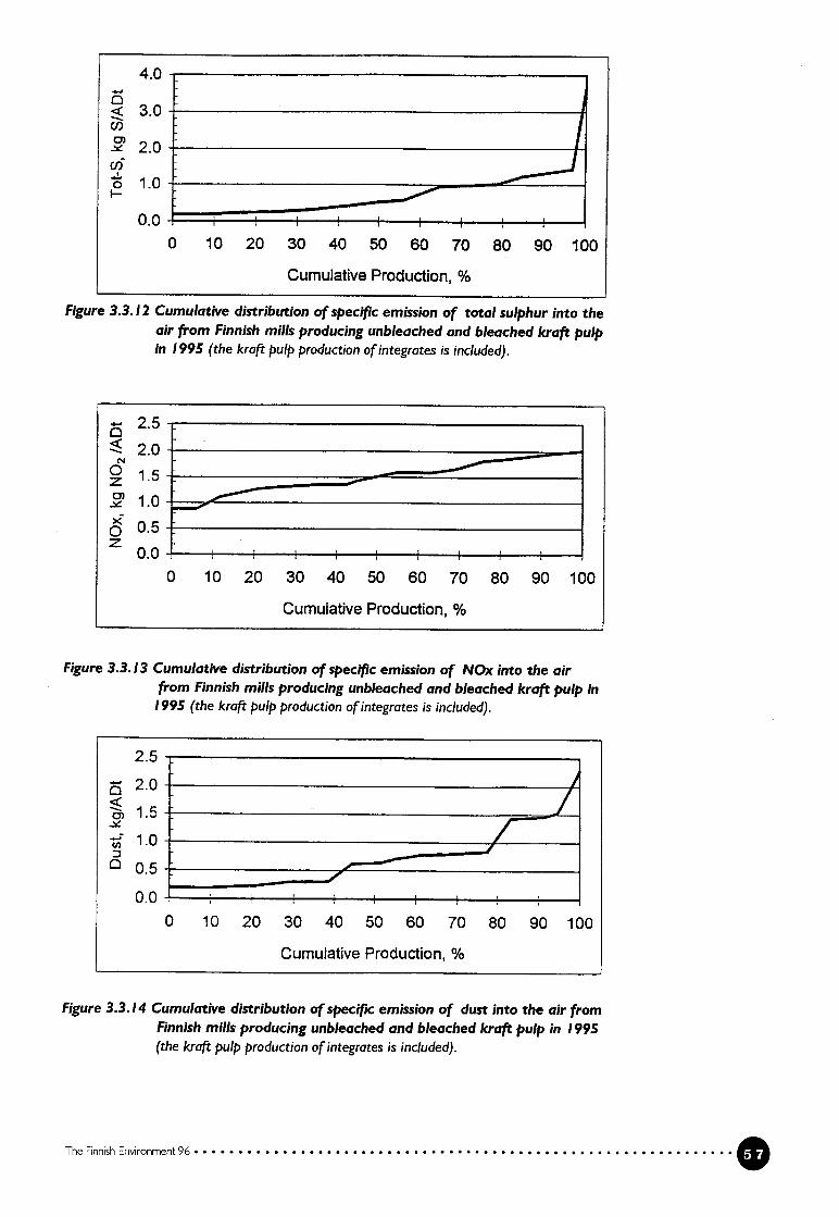
Cumulative Production, %
Figure 3.3.12 Cumulative distribution of specific emission of total sulphur into theair from Finnish milis producing unbleached and bleached kraft pulpin 1995 (the kraft pulp production ofintegrates is included).
2.5
2.00z0).
xo 0.5
0.0
Figure 3.3.13 Cumulative distribution of specific emission of NOx into the airfrom Finnish milis producäng unbleached and bleached kraft pulp in1995 (the kraft pulp production ofintegrates is included).
The Rnnish Environment 96
(1)0)
0
4.0
3.0
2.0
1.0
0.00 10 20 30 40 50 60 70 80 90 100
0 10 20 30 40 50 60 70 80 90 100
Cumulative Production, %
2.5
2.0
0)
1.0
0.5
0.0
0 10 20 30 40 50 60 70
Cumulative Production, %
80 90 100
Figure 3.3.14 Cumulative distribution of specific emission of dust into the air fromFinnish mills producing unbleached and bleached kraft pulp in 1995(the krcift pulp production ofintegrates is included).

3.4 Mechanical pulp
In mechanical pulping the wood fibres are separated from each other by mechanical energy. The action of forces creating a strain on the wood matrix causes thebonds between the fibres to break graduafly and fibre bundies, single fibres andfibre fragments to be released. It is the mixture of fibres and fibre fragments thatgives mechanical pulp its favourable printing properties. The wood matrix hasviscoelastic properties and the softness can be influenced by chemicals and/or anincreased temperature. A softer wood wffl release more intact fibres. The moisturecontent in the wood is of major importance for the pulp properties as it ffifluencesthe softening of the wood. If the fibres are liberated before the ligrdn is soft enough,the fibres are easily damaged and resuit is a pulp with short fibres, a high contentof fines and limited strength properties. If the moisture content in the wood islow, the temperature in the wood can rise S0 high that the wood changes colour -
the wood burns. To prevent the wood burning, process water has to be added tocool the process.
There are two main types of equipment, grinders and disc refiners, used formechanical pulping. In the grinders the wood is in the form of logs and in the discrefiner it is in the form of chips. The use of chips makes the refiner-based pulpingsomewhat more versatile with regard to the supply of the raw material and different types of pre-treatment of the wood before pulping.
The elements causing the mechanical action, grits on a pulp stone in the grinder and bar edges on a steel disc in the refiner, wiIl give the resulting pulps atypical blend of fibres and fibre fragments. The groundwood pulp coming fromthe grinders wffl hold a higher proportion of fine material and damaged fibres.This gives the pulp good optical and paper-surface properties, which is valuablem low grammage printing papers. The more gentle treatment in the refiners produces a higher yield of intact long fibres. This gives the pulp higher strength,which is valuable in furnishes for products with a high requirement on runnability.
In the refiners and grinders the applied energy is converted through the friction created into heat. In the refiner the released heat vaporizes part of the waterpresent and the process heat is recovered in the form of steam, which is used fordrying the paper or board.
The characteristics of the pulp can he affected by increasing the processingtemperature and, in the case of refining, by the chemical beatment of the chips.Both steps will increase the energy consumption as well as the pollutant levelbecause of a lower pulping yield.
Spruce is the favoured raw material for mechanical pulping in Finland. Lately there has been increasing interest in the use of aspen because of the favourableoptical and paper-surface properties of aspen pulps.
3.4.! Mechanical pulping processes
Groundwood Pulps (GW, TGW, PGW, PGW-S)
In the conventional groundwood process debarked wood logs are pressed against
a grinding stone in a grinder at atmospheric pressure. The mechanical work is
mainly transformed into heat and the temperature of the wood rises. The Iignin
O The Finnish Environment 96

softens and the bonds holding the individual fibres together weaken. The highamount of shower water used results in a consistency close to 1 to 2% after thegrinder. The temperature of the shower water is normally 70•800 C.
By increasing the pressure in the grinder it is possible to raise the grindingtemperature. Due to the higher temperature the wood is softer in pressurisedgrinding (PGW, PGW-S) than m conventional grinding (GW) and the fibres areless damaged.
Grinder-based pulps are divided into two main types, as shown in table 3.4.1,on the basis of the grinding pressure and shower water temperature.
?able 3.4.1 Main types of groundwood pulp
oundwood pulps Abbreviation Shower water Pressuretemperature( °C) (bar)
roundwood GW 65-75 0Chermo groundwood TGW 70 - 80 0.02-0.03‘ressure groundwood PGW 70 - 100 2-3uper pressure groundwood PGW-S 95 - 125 4-4.5
In the PGW process low-pressure steam is generated when the pulp siurry flashesin the blow cyclone. The recovered low pressure steam is mainly used for theproduction of warm process water.
Refiner Mechanical Pulps (RM TRM TNI PRM CRM CMITMR CTMP)
In refiner mechanical pulping, chips are ground between steel discs with bar patterns in a refiner. Depending on the quality, the refining can be repeated in asecond-stage and sometimes even a third-stage refiner. The forces from the impact of the bars causes the chips to break down into fibre bundies, individualfibres and fibre fragments. With the progressing treatment the impact also modities the walls of the individual fibres. Most of the applied energy (fiction work)transforms into heat which flashes part of the moisture in the chips. To preventthe wood from burning in the refining zone, cooling (dilution) water has to beadded. The refiners normally operate at a high discharge consistency (25-50%).The large quantity of steam released in the refining process is normally capturedin a heat recovery system for further use.
In the original refiner pulping process (RMP) chips were refined at atmospheric pressure. Because of the low temperature the process produced a high amountof damaged fibres. The optical properties of the RMP pulp were relatively good.RMP systems have not been installed in Finland since the early 1970’s.
To improve the pulp quality, process modifications aiming at increased softness of the wood in the refining zone have been applied. These included the preheating of chips (TRMP and TNP) or pressunzation of the refiner (PRMP). Theseprocesses produce pulps of slightly higher strength and reduced shive level atalmost unchanged optical properties.
A more dramatic strength improvement and shive reduction is gained in theTMP process, where the chips are heated under pressurised condifions and therefining is also pressurised. Because of the pressurised conditions the released
The Finnish Environment 96 O

steam can be used for the generation of steam that can be used in the drying of
paper. The increased refining temperature has an adverse effect on the optical
properties and increases the consumption of electrical energy.
Mild chemical pre-freatment of the chips also enhances the softening of the
wood and improves the properties of pulp produced by refining at atmospheric
pressure (CRMP) or pressurised refining (CTMP). In most cases chemical pre
treatment increases the energy consumption. The generation of pollutants also
increases as a consequence of the yield loss caused by the chemical treatment.
Different kinds of treatment are used for different wood species. Sodium sulphite
is mostly used for softwoods, and lately alkaline peroxide has been predominant
ly used for hardwoods. The alkaline peroxide treatment reduces the energy con
sumption. These methods produce clean pulps of sufficient strength and accep
table optical properties and can be used as the main fibrous component in printing paper, packaging board and hygienic paper furriishes.
With stronger chemical treatment and refining at atmospheric pressure, pulps
(CMP) with high-sfrength properties can be produced from both softwood and
hardwood. Optical properties are drastically reduced and CMP can only form a
minor part of the furnish for printing papers. In CMP pulping the yield can falibelow 90%. Both the increase in the refimng temperature and the use ot chemicals
have increased the generation of pollutants in mechanical pulping. The main fea
tures of the refiner pulping processes are shown in table 3.4.2.
Table 3.4.2 Main types of refiner mechanical pulpS
efiner mechanical pulp Abbreviation Chip Refining Energypre-treatment pressure recovery
potential
efiner Mechanical Pulp RMP None Atmospheric Low
‘hermo Refiner Mechanical Pulp TRMP Steam at Atmospheric Low
atmospheric
pressure
‘hermal None Pressurised TNP Steam at elevated Atmospheric Low
pressure
:hemi Refiner MechanicaL PuIp CRMP Chemical Atmosphenc Low
lemi Mechanical Pulp CMP Heavy Chemical Atmospheric Low
+ pressurised
heating
ressurised Refiner Mechanical PRMP None Elevated Moderate
‘ulp pressure
‘hermo Mechanical Pulp TMP Pressurised Elevated Moderate
heating pressure
hemi Thermo Mechanical Pulp CTMP Mild Elevated Moderate
chemical and pressure
pressurised
heating
The Finnish Environment 96
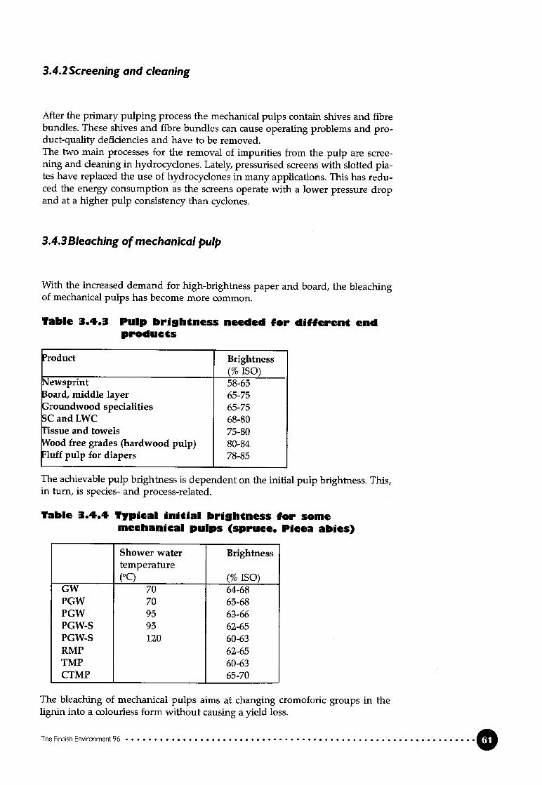
3.4.2 Screening and cleaning
After the primary pulping process the mechanical pulps contain shives and fibrebundies. These shives and fibre bundies can cause operating problems and product-quality deficiencies and have to be removed.The two main processes for the removal of iinpurities from the pulp are screening and cleaning in hydrocyclones. Lately, pressurised screens with slotted piates have replaced the use of hydrocyclones in many applications. This has reduced the energy consumption as the screens operate with a lower pressure dropand at a higher pulp consistency than cyclones.
3.4.3 Bleaching of mechanical pulp
With the increased demand for high-brightness paper and board, the bleachingof mechanical pulps has become more common.
Table 3.4.3 PuIp brih(ness needed for different endproducts
‘roduct Brightness(% ISO)
Jewsprint 58-65oard, niiddle layer 65-75roundwood specialities 65-75
C and LWC 68-80issue and towels 75-80Vood free grades (hardwood pulp) 80-841uff pulp for diapers 78-85
The achievable pulp brightness is dependent on the initial puip brightness. This,m turn, is species- and process-reiated.
Tabio 3.4.4 Typical initial bri9htness for somemechanical pulps (spruce, Picea abies)
Shower water Brightnesstemperature(°C) (% ISO)
GW 70 64-68PGW 70 65-68PGW 95 63-66PGW-S 95 62-65PGW-S 120 60-63RMP 62-65TMP 60-63CTMP 65-70
The bleaching of mechanical pulps aims at changing cromoforic groups m thelignin into a colourless form without causing a yield loss.
The Finnish Environment 96

There are two main chemicals used in the bleaching of mechanical pulps, dithio
nite and peroxide. Ditbionite bleaching is a reductive method, while peroxidebleaching is oxidative needing a high pH environment.
Dithionite bleaching
In dithiomte bieaching organic material is not dissolved from the pulp.The maximum econonucal charge of dithionite is 8 to 12 kg per tonne of pulp. A
higher dosage does not increase the brightness. The brightness is increased fromthe initial brightness level of 58-70% ISO to 70-76% ISO. In most mifis a metalchelating agent (e.g. EDTA, DTPA) is used. The consistency m conventionai hydrosulphite bleaching is 3-5%. Medium consistency (MC) pumping has made itpossible to bleach at a 10-12% consistency with increased efflciency.
Peroxide bleaching
The yield drop m peroxide bleaching is approximately 2%, mainly due to thealkalinity during the bleaching. This irifluences the pulp properties: in additionto the increase in brightness, the strength of the puip improves, the content ofextractives is reduced and the water uptake capacity improves.
A higher final brightness can be reached with peroxide bleaching than withdithiomte bleaching but the consequence is reduced opacity. The maximum ef
fect of peroxide bieaching changes from the initial brightness 58-70% ISO to afinal brightness 78-84% ISO. The maximum economical amount of peroxide is 3-4% of the amount of pulp.
The pH is adjusted with sodium hydroxide. Sodium silicate is added (1.5-
4% of the amount of pulp) to buffer the pH and stabiise the peroxide. Chelatingagents (e.g. EDTA, DTPA) are used to form complexes with heavy metais (Fe, Mn,Cu, Cr), which prevents the pulp from discoiouring and the peroxide from decomposing. The dosage of chelating agents is about 5 kg per tonne of pulp. EDTAand DTPA contain nitrogen, which wffl show up in the waste water. The bleachedpuip is finally acidified with sulphuric acid or sulphur dioxide to a pH of 5-6.
Modern peroxide bleaching is conducted at a consistency level of 25-35%.
3.4.4PuIp properties and end-users of mechanical pulps
Mechanical pulps do not have the same strength as chemical pulps, but recentdevelopments have led to considerable improvements. Mechanical fibres do notform fibre bonds to the same extent as chemical fibres. This gives the paper betteroptical characteristics, i.e. higher opacity.
Mechanical puips are often characterised by their drainage properties. Aftequently used measurement is the Canadian Standard Freeness, CSE A iow
freeness vaille indicates a siow draining pulp with a high degree of fibrfflation.Such a pulp has been produced using a high energy input in the grinding or
refining.The paper and board in which mechanical pulp is used determine the requi
rements for freeness, brightness and other pulp properties. Today mechanicaland chemi-mechanical puips are produced in different commercial processes in a
very wide freeness range for a variety of paper and board grades. Wood contai
0 The Finnish Envjronment 96

ning printing paper, e.g. LWC, SC magazine paper (freeness 20-60 ml CSF) andnewsprint (freeness 80-150 ml CSF) are the most common end products. The pulpsare also used in paper board (fteeness 450-750 ml CSF), absorbent products, e.g.tissue (300 ml CSF) and fluff (700 ml CSF), and hardwood grades iii fine paper.
Pulps intended for different end uses have a distinct distribution of longfibre, middle and fine fractions. The distribution between long fibres and finematerial in a specific pulp is, besides the degree of softening of the wood, controlled by the energy input. Generally, ground wood pulp has a lower long fibrecontent and strength, but a higher fines content than refiner pulp. Groundwoodpulp gives the paper good optical properties.
3.4.5Raw materiais, pulp yield and energy consumption
To obtain a product of optimum quality, it is necessary to have access to the besttype of wood for a certain application. This wffl be of special importance in theyears to come, when the quality demands on the high-yield pulps wffl increaseconsiderably. Mechanical pulping is more restrictive in terms of the wood typesthat can be used as a raw material than chemical pulping.
The best wood raw material for mechanical pulping processes is spruce andaspen. Norwegian spruce (Picea abies) is one of the best raw materiais for bothgrinding and refining. The brightness in aspen ground wood is good but thestrength of the pulp is lower compared with spruce pulp. One reason for developing chemi-mechanical pulping processes was a higher-strength pulp.
The yield from mechanical pulps varies between 92% and 97% and withoutchemical treatment the yield is above 94%. The reduction of the pulp yield inperoxide bleaching is 1-2%.
The specific energy consumption iii mechanical pulping is dependent onthe pulping process, the properties of the raw material and, to a large extent, thequality demands on the pulp set by the end product. The freeness value is usually used for specifying the quality of the pulp. For the manufacturing of a pulpwith better strength (low freeness) the energy consumption is increased.
Only a portion of the mechanical work put into the grinder or refiner is usedto liberate the fibres in the wood. The rest of the work is turned into heat. Theheat that is released can be recovered for other usages such as the drying of thefinal product. Typical recovery rates are shown in table 3.4.6. The lower figures inthe energy usage range are for high-freeness pulps used in boards, and the higherfigures are for low-freeness pulps used in high-quality printing papers.
The consumption of energy in screening, cleaning, reject handling, postrefining and bleaching is dependent on the quality demands set by the products.
The Finnish Environment 96

Table 3.4.0 Ener9y consumption and reeovery ofenergy in mechandcal pulping.
vlechanical pulp and Energy Recoverable energyreeness, ml CSF consunlption
as hot water as steam(kWh/t of pulp) (%) (%)
W 350-40 1,100-2,000‘GW 350-40 1,300-2,300 30‘GW-S 350-40 1,300-2,300 30{MP 350-30 1,500-3,000 70MP 400-30 1,800-3,000 20 60TMP 700-40 1,000-3,300 20 60
3.4.6Discharges and emissions into water and the air, generationofsolid waste
A yield of 92-97% means that 30-80 kg /tonne of the wood are lost in the water
phase in the form of dissolved and dispersed organic substances. The yield isdependent on the energy mput and the temperature in the process and on the
use of chemicals. Wood species and seasonal variations also influence the amount
of dissolved solids. During mechanical pulping, the stability of the cellulose and
the lignin is not affected, but simple carbohydrates, extractives, proteins and in
organic substances mcluding nitrogen and phosphorus are dissolved and dis
persed in the process water.With a decreasing yield the BOD7of the water from pulping increases. Typi
cal specific loads measured such as BOD7,CODCr and nutrients (phosphorus and
nitrogen) for different pulps are listed in table 3.4.7.
Table 3.4.1 I’ypical specifdc Ioads such as BOD,,COD and nutrents in water from themechanical puIpin of Norwegian spruce(Plcea abies) before external treatment.
‘ulping process Yield BOD7 CODCr Nitrogen Phosphorus
(%) (kg/t) (kg/t) (g/t) (g/t)W 96-97 10-12 20-30 80-100 20-25
‘GW 95-96 12-15 30-50 90-110 20-30‘GW-S 95-96 13-16 45-55MP 95-96 12-17 40-60 90-110 20-30[MP 94-95 15-25 50-80 100-130 30-40TMP 92-94 20-35 60-100 110-140 35-45
The discharge of nitrogen in mechanical pulping onginates from the wood and
chelating agents (e.g. EDTA; DTPA) used in bleaching. A dosage of 2-3 kg EDTA/torme of pulp results in an additional discharge of 150-220 g nitrogeriJtonne of
pulp. The discharge of phosphorus depends on the wood.The yield loss in connection with peroxide bleaching is 15-30 kg/tonne cor
responding to an additional load of approximately 10-30 kg OJtonne measured
as BOD7and CODCr respectively. The steam released in mechanical pulping pro
cesses is contaminated with volatile wood components. The amount of steam,
Ø

dependent on the specific energy consumed, is some 2 tonnes per tonne of pulpat a pressure of 2 to 4 bar. The contaminated condensate can be treated separate
‘YO
In a typical mtegrated board or paper mifi that uses mechamcal pulp highpressure steam is generated in a power plant. The energy is partially transformedinto electricity in a back pressure turbo-generator and the rest is used in paper orboard drying.
The fueis used are coal, bark, oil and natural gas. Approximately 20% of theelectricity requirement at the miii is covered. The power plants have electrostaticprecipitators for the removal of particulates from the flue gases. The emission ofsulphur dioxide is limited by using selected fueis.
The solid primary waste removed from the mechanical pulping processesconsists of bark and wood residues from the debarking, fibre rejects, ash fromenergy production and sludges from external waste water treatment (see section3.2 and 3.7).
3.5 Recycled fibre
The use of recycled fibre in paper and board manufacturing is increasing rapidly.After deinking, recycled fibre can be used in tissue paper, newsprint and evenfine paper. Recycling waste paper reduces the amount of solid waste going forlandfill although the deinking of recovered waste paper generates a considerableamount of deinking sludge that usually goes for landfffl.
In Finland the use of waste paper was about 5% of the raw material used inpaper and board production in 1994 and 1995 (472,300 and 492,000 tonnes respectively). The recovery of the total paper and board consumed in Finland in1995 was 58% of the recoverable paper and board consumption. The Finnish useof recycled fibre cannot be increased without increasing the import of waste paper or recycled fibre because about 90% of the total production of paper andboard is exported.
Most of the recycled fibre originates from household waste paper, consisfingof newspapers (65-70%), magazines (20%), leaflets and other paper products(10-20%).
Recycled fibre is used in newsprint (33%), tissue (24%) and as a raw materialfor different board grades (37%), replacing mechanical pulp. Newsprint can bemade of 100% recycled fibre, but the average in Finnish newsprint is lower. Intissue paper the use of recycled fibre varies between 0 - 100%. Recycled fibre thatis not deinked is used in the middle layer of multi-layer board and in core board.A small amount of recycled fibre is also used in magazine paper. Recycled fibresftom brown packaging grades are reused in siniilar grades.
3.5.! Recycled fibre processes
Recycled fibre processes can he divided in two categories:- processes with only mechanical cleaning- processes with mechanical and chemical cleaning.
The target in recycled fibre pulping is to minimize the content of ail kinds ofcontaminants in the pulp and to preserve the strength of the pulp.
The Finnish Environment 96

The quality, cleanness and brightness requirements for the recycled fibre used asa fibre raw material vary widely with different paper and board grades. In manyboard grades deinking is not required, but for high speed paper machines manufacturing high-brightness paper very efficient multi-stage processing is normallyrequired.
The main stages included in the recycled fibre processes are:- coarse classification- repulping of waste paper- removal of mechanical impurities- removal of chemical impurities- mechanicaVchemical dispersion of remaining contaminants- bleaching
Deiriking is necessary for grades where brightness is important such asnewsprint, printing and writing paper, tissue, and the top and bottom layers inmulti-layer white boards.
Deinking is based on washing the pulp in order to remove the printing mk.A deinlcing plant includes the following urut operations : repulpmg, prescreening for the removal of coarse contaminants, the chemical treatment of thepulp, deinking by fiotation and/or washing, fine screening, cleaning and dewatering. The order of the unit operations may vary and some of the steps may berepeated either with the same or different types of equipment. Typicai chemicaldoses in the deinking process are shown in table 3.5.1.
Table 3.5.1 Chemicals in deinkin
hemical Use(kg/tonne of pulp)
odium hydroxide 10-20odium silicate 20 - 30oap 5- 8
EaIc 10-15Iydrogen peroxide 5 - 25Ielating agent (DTPA) 2 - 3odium dithionite 6 - 10ulphuric acid 8 - 10
The yield of deinked pulp is 60-90%.There are four deinking plants in Finland. The largest plant has an annual
capacity of 100,000 tonnes. The raw material is unsorted household waste paper.The pulp is used for the on-site production of newsprint.
The amount of deinking sludge from the fiotation unit is about 65 kg/tonneof recycled fibre. The deinlcing sludge and the reject from fine screening are burnt
in the power plant. The process water is freated by dissolved air fiotation (DAF)before external biological treatment. The punfied water is not recirculated intothe deinking process. The water used in the process is mainly white water fromthe newsprint paper machine.
Two deinldng plants produce recycled fibre for tissue papers (capacity 60,000
tonne/a and 45,000 tonne/a). The raw material is not only household waste paper
but also white woodfree and wood containing office paper depending on thequality requirements of the end product. The amount of deinking sludge varies
considerably depending on the waste paper quality, and it can be as high as 240kg/tonne of recycled fibre.
The Fjnneh Environment 96

One plant produces market pulp. The annual capacity is about 60,000 tonnes.The raw material is household waste paper. The pulp is mainly used in manufact-uring newsprint, magazine paper and tissue. The deinking generates about 85kg of deinling sludge per tonne of recycled fibre. The deinking sludge is dewatered by centrifugation to 40-50% dryness. Ali rejects and deinking sludge go forlandfill. The process water is internally treated by DAF and partially reused.
3.5.2 PuIp properties and end use
Recycled fibre has conventionally been used mostly in packaging and some othercardboard grades. Deinking is not usually necessary for these grades. Deinkedpulp is mostly used in tissue and newsprint and in smaller amounts in printingpaper grades of a higher quality.
The use of recycled fibre instead of primary fibre in most cases weakens thequality of the paper. For example, recycled fibre decreases the stiffness of theboard. To compensate for tKis, more pulp is used in the board (up to 30%). Due tothe higher grammage the energy consumption of the board machine increasesand production efficiency decreases.
Relatively high amounts of bacteria have been found in packaging materiais containing recycled fibre.
3.5.3 Energy consumption
The consumption of electrical energy is approximately 300 kWh/tonne of pulp.The use of waste paper has risen simultaneously with the increase in the demands for quality placed on the end products. Small amounts of recycled fibrecan be used in more demanding paper grades like LWC and SC. This requiresadditional cleaning stages and the electrical energy consumption wffl increase to500 kWh/tonne.
Pumping consumes almost half of the energy, screening and dispersing aboutone third and pulping, agitation and venifiation take up the remaimng 20%.
The consumption of heat energy in the processing of recycled fibre is 1.1-2.4GJ/tonne.
3.5.4 Discharges and emissions into water and the air,generation of solid waste
Because of different quality requirements the recycled fibre processes are designed in various ways. The composition of the waste water is dependent on theoperating principle of the deinking process, raw material and the quality requirements on the produced pulp. Three of the Finnish deinking plants were investigated in 1991. In stable process conditions the primary discharge of organic substances was 30-35 kg as CODC/ADt of pulp. The average discharge of phospho
The Rnrush Environment 96

rus and nitrogen varied between 20-60 g/ADt and 175-400 g/ADt respectively.
Fatty and resin acids occurred only in small amounts. The amount of AOX was 5-
10 g/ADt. The content of heavy metais was low.Waste water sampies were taken after fiotation but before external biological
treatment.The use of recycled fibre to replace mechanical pulp in paper or board mc
reases the amount of solid waste generated. Depending on the waste paper qua
lity and the requirements for the recyded fibre, the amount of solid waste varies
considerably (10-40% of the raw material). About 10% are rejects such as metal,
sand, plastics etc. The amount of deinking sludge is 50-250 kg dry matter/tonne of
recycled fibre.
3.6 Paper and boardThis section describes Finnish paper and board production. The discussion is iimited to grades in which Finland plays a major role within the EU.
3.6.1 General
Production processes
Traditionally the production has been divided into integrated or non-integrated
production depending on whether the main raw material, pulp, has been produ
ced at the same site.Almost ail types of paper and board-making processes have the following
basic units:- stock preparation- a paper or board machine consisting of
- a wire section- a press section- a drying section- a reelerDependmg on the paper and board grade there are additional process units,
like calenders, coaters, a coating colour kitchen, winders, rewinders and a roll
wrapping station.In the stock preparation the pulp might be refined, and before being pum
ped to the paper machine it is cleaned for the removal of impurities. Frequently
centri-cleaners and screens are used in series.The fibre suspension is diluted before the inlet to the paper machine (head
box) to a consistency of 0.2-1.5% in order to obtain a uniform fibre distribution in
the web formed on the wire. In the wire section the pulp suspension is dewate
red to a consistency of about 20% by ifitration. The fiitrate called “white water” is
valuable because of its fibre, fiiler and heat content. The white water is collected
and reused for pulp dilution before the paper machine. This circulation of white
water is called “the short circulation”.The retention of suspended solids on the wire varies 50-80% depending on
the paper grade being produced. For paper grades contairiing mechanical pulp
and fifier the first-pass retention is usually lower than for grades made ftom che
mical pulp.
The Finnish Enwonment 96

In the press part the pulp is further dewatered to a 35-52% consistency and in thedrying section the paper web is dried to 90-95%. The total amount of water entering the wet end always exceeds the amount of water needed for the short circulation dilution. The excess water is collected, treated and reused for the dilution(long circulation) of the pulp in different parts of the process. Clean, fresh wateris used for shower water in the wire and press sections and for sealing and lubrication. This fraction of the fresh water leaks into the white water system, givingrise to excess white water, which is normally extracted as a clear filtrate. The freshwater used for cooling and sealing the vacuum system remains unpolluted andis, therefore, returned to the fresh water system or discharged, by-passing anytreatment. The total consumption of fresh water is 15-50m3/tonne of paper. Theexcess white water is treated for fibre recovery. A typical water circulation systemfor a newsprint machine is presented in figure 3.6.1.
In the process some paper, broke, not approved for shipping is generated. Thebroke nevertheless contains some valuable raw material and is, therefore, returnedto the process.
Energy consumption
About 90% of the heat energy is used for drying of the paper and the rest is usedfor heating the process and the building. Paper machines integrated with TMPproduction use steam from the heat recovery of the TMP plant. Part of the electricity needed is produced in back pressure turbines; the rest is purchased. Specificenergy consumptions typical for different paper grades are given in table 3.6.1.
The Hnnish Environment 96
Figure 3.6.! Block diagram of a newsprint miii

The average distribution of electrical energy consumption in Finnish paper mifis
is- pumping of raw materiais and water 25%- vacuum system, ventilation, pressurised air 25%- drives, refiners, screens 38%- electrical - IR drying 9%- lighting and other uses 3%
Tablc .6.I Typical average specific energyconsumption figures for differentpaper grades (1992).
‘aper grade Consumption of Consumption ofelectrical energy heat energy(kWlVtonne of paper) (GJ/tonne of paper)
Jewsprint 600 5.3‘Vood containing paperSC 700 5.3LWC 700 5.3
Fine paper 750 7.5Sack paper 1100 6.9White board 800 7.2Liner and fluting 520 5.7Tissue 1000 6.9
The figures do not include the energy consumption in the pulp production.
Internal pollution control
The main principles for internal process measures are the reduction of fresh wa
ter consumption by recyding the process water, the reduction of fibre and otherraw-material losses and the separation of uncontaminated water from contaminated. Excess white water is clarified before being partially discharged. The reuseof a clear ifitrate replacing ftesh water is common practice in several applications.However, the separation of suspended solids alone is not sufficient in cases where, for instance, slime growth causes disturbances.
Steps typically taken to reduce the fresh water consumption at the paper
and board machines include the segregation of contaminated and clean streamsand the reuse of the clean water fraction in the first place. On many machines SO
called save-ail filters have been installed with which valuable material is recovered from the white water, and a clear fraction, free of suspended solids, is obtamed. This clear filtrate can be used to replace fresh water in showers and in the
pulp miii. Any excess filtrate is discharged into the external treatment system.This maintains the balance of dissolved solids in the water system.
Lower fresh water consumption results in lower volumes going to the exter
nal waste water treatment, lower water costs and higher temperatures in the pro
duction system, which leads to lower steam consumption in the paper-dryingsection.
Spills, overflows of pulp and white water into the sewers occur in the opera
tion of a miii. The effects and frequency of the spffls can he reduced by the design
and control of the white water system, the production system and by training the
personnel.
O The Finnish Environment 96

Discharges and emissions into water and air, generation ofsolidwaste
The main types of process water discharged from a paper machine are rejectsfrom pulp cleaning and excess white water. Temporary discharges and spills (overflows of tanks, spent wash water from cleaning equipment and flushing waterfrom flushing floors etc.) occur intermittently.
The spent cooling water and the vacuum-system sealing water are generallyclean and can be recycled to some extent. Clean cooling water should he keptseparate from polluted effluents in order to minimize the hydraulic load m theexternal treatment plant.
The amount of suspended solids primarily discharged from the process depends on the internal measures taken at the paper miii and on accuracy of operation. The main sources are cleaner rejects, occasional spffls and excess white water. Most of the discharged suspended matter is separated in the primary treatment and the separated sludge is dewatered and disposed of.
The dissolved orgamc matter discharged from the paper production systemconsists of substances carried over from the integrated pulp miii or, m the case ofpurchased pulp, from refining the pulp and from chemical additives at the papermiii. The amount of organic substances generated at the paper miii normally corresponds to 1-5 kg/tonne and 2-10 kg/tonne of paper measured as BOD7 andCODCrY respectively, before external treatment.
The degree of closure of the white water system normally has only a minorinfluence on the amount of discharged organic matter. The amount of water to hedischarged wiII decrease with a higher closure degree and, therefore, the concentration of organic matter in the effluent wffl increase. With increased concentration there is a risk of a carry-over of organic matter from the process water tothe finished paper if no internal water treatment is used.
The emissions into the air from paper mifis consist of moist air from the dryingsection and flue gases from the energy production at the mifi.
The main types of solid waste in connection with paper production are rejects, sludge and ashes. Other solid waste like metal, plastics, glass, chemicals,coating residues etc. are generated in smaller quantities.
Cleaning the pulp before pumping into the paper machine generates rejectsthat contain impurities like shives bark, sand, fibres etc. The dry solid content ofthe rejects is low (1-2%), and the rejects are normally discharged into the effluentcollection system. In an integrated miii the screening reject may be recycled intothe pulp miii. Most of the rejects end up in the sludge from the effluent treatmentsystem.
Coating colour residues contain expensive components such as pigmentsand binders. The recovery of waste from the coating colour preparation is economically feasihle. Furthermore, due to the high content of inorganic pigments thewaste is less suitable for mixing with fibrous sludge meant for incineration.
3.6.2 Newsprint
The fact that a newspaper becomes old in one day and is then recycled or disposed of makes it possible and necessary to use cheap mechanical pulp and demked recycled pulp as the fibre raw material. The basis weight of newsprint hasbeen decreased from 52 g/m2to 45 and even 40 g/m2 during the Iast two decades.
The Finnish Environment 96

More printing area is gained but simultaneously the importance of sufficient opa
city has grown. This demand is met by a high proportion of mechanical pulp in
the furnish.Traditionally, newsprint has been made of 70-85% groundwood pulp, the
rest being chemical pulp. With the development of strong TMP pulps, newsprint
production without chemical pulp has become possible during the last decade.
Newsprint is now manufactured from TMP and /or deinked recycled fibre and
only in the lightest grades is a small amount of chemical pulp used.One of the main disadvantages of mechanical pulp is the strong yellowing
that turns the paper yellow in a very short time when it is left in the daylight. But
as the lifetime of a newspaper is short, this is of less importance. The initial brightness of mechanical pulp is normally 60-65% ISO, which is high enough fornewsprint. Hydrosulphite bleaching is sometimes used, but peroxide bleaching
is too expensive for normal newsprint grades. Some high brightness specialnewsprint paper grades are produced ftom peroxide bleached mechanical pulp.
Some chemicals are used in the production of newsprint, like dyes for shading, and in some cases ffllers (5-10%), retention aids and slimecides.
Ali newsprint milis are integrated with mechanical and/or deniked pulpmg.
The white water system of the paper machine is integrated into the process water
system of the pulping. The effluent load from the paper machine and from thepulp production cannot, therefore, be separated. The waste water can be dischar
ged from both departments, but since most of the organic substances are dissol
ved during the pulp producfion, fresh water should be used at the paper machi
ne and Ied counter-current to the pulp and discharged from the pulping plant.
The total ftesh water consumption m a modern newsprint miii is 15 -20m3/tonne
of paper. In older milis the water consumption can be up to 40m3/tonne of paper.
A block diagram of a typical newsprint miii is shown in figure 3.6.1.
3.6.3Magazine paper
There are two main grades of magazine paper, uncoated supercalendered (SC)paper and light weight coated (LWC) paper. The basis weight is in the range of40-70 g/m2 for SC paper and 50-70 g/m2 for LWC paper. The basis weight of the
base paper in LWC paper is 30-45 g/m2 and the paper is coated on both sides (7-15
g/m2).The pulp raw matenal in SC paper is bleached mechanical pulp and bleach
ed chemical pulp. A typical furnish for SC paper is 50-60% mechanical pulp, 10-
25% chemical pulp and fifier clay 15-35%. The surface is finished by supercalen
dering.The base paper furnish for LWC paper is mechanical pulp 40-60% and 30-
50% chemical pulp. Ffflers are not usually used. The coating is composed of pig
ments, latex and starch binders. The coating is 15-35% of the final LWC paper
weight. The paper is coated on- or off-machine. The paper is finished by superca
lendenng.The mechanical pulp is, in most cases, bleached with peroxide.
The Finnish Environment96

Stock preparation and paper machine
The stock preparation for SC paper includes two (or more) pulp lines, one formechanical pulp and the other for chenucal pulp, a broke handling system andfacilities for the preparation and dosage of fillers.
A simple block diagram of an SC paper mifi is shown in figure 3.6.2.The stock preparation for LWC paper includes two pulp lines, two broke
handling systems and a preparation and dosage system for coating agents. A simple block diagram of an LWC paper miil is shown in figure 3.6.3.
The coating is prepared in the coating kitchen.Retention aids, slimicides and dyes are added at the paper machine wet
end. Starch is often added to improve the strength properties.
The Finnish Enronment 96
Figure 3.6.2 Biock diagram ofan SC paper miii
Frcsh water
Figure 3.6.3 Biock diagram ofan LWC paper miii

3.6.4 Woodfree printing and writing paper
Paper used for documents archived for a iong period of time has to retain its
coiour and integrfty. For these reasons woodfree paper, also called fine paper, is
made from bleached chemical pulp with the addition of a filler. Fine paper grades
are sized, both internally and on the surface, in order to achieve low mk penetra
tion. To achieve improved printability the paper is coated.
Fine paper is used for printing, writing and copying. Fine paper mostly con
tains 20-30% filler clay. In neutral and alkaline paper-making calcium carbonate
is used.The basis weights vary m the range of 40-200 g/m2 depending on the purpo
se for which the paper is used. The basis weight of copy paper is 75-80 g/m2.Art
paper, which is used for high-quality books and advertising publications, is co
ated twice or even three times. Up to 40% of the dry content of the final paper
consists of coating in a double coated paper. The basis weight of art paper is 80-
200 g/m2.Hydrophobic sizing is used to prevent liquid penetrating the paper. Almost
ail fine papers undergo surface sizing, which increases the stiffness, surface st
rength and internal bonding. Surface sizing is performed in a size press. Surface
sizes are starch-based, which is important in terms of the effluent composition
and discharges.Sizes (starch or synthetic), dyes, retention aids, slimecides etc. are used at
the paper machine wet end.Fine paper milis can be non-integrated or integrated with a chemical pulp
miii. In Finland ali the fine paper mifis are integrated. Even if a fine paper mii is
integrated with a puip mifi, no white water from the paper miil is used in the
pulp production. This means that the paper mill’s water balance is influenced by
the amount of water accompanying the puip at the pumping consistency. The
effluent from an mtegrated paper miii is 15 - 30m3/tonne of paper and 10 - 20 m3/
tonne of paper for a non-integrated paper miii. As far as the total water consump
tion is concerned, it would be most feasible to return an equal amount of clear
white water filtrate to the pulp mifi to compensate for the loss of process water
that normally consumes fresh water. A block diagram for a typical fine paper miiiFigure 3.6.4 Block d:ag-5 shown in figure 3.6.4.ram ofa fine paper miii
Fresh water
To effluent trectment
To effluent treotment
The Finnish Envronment96
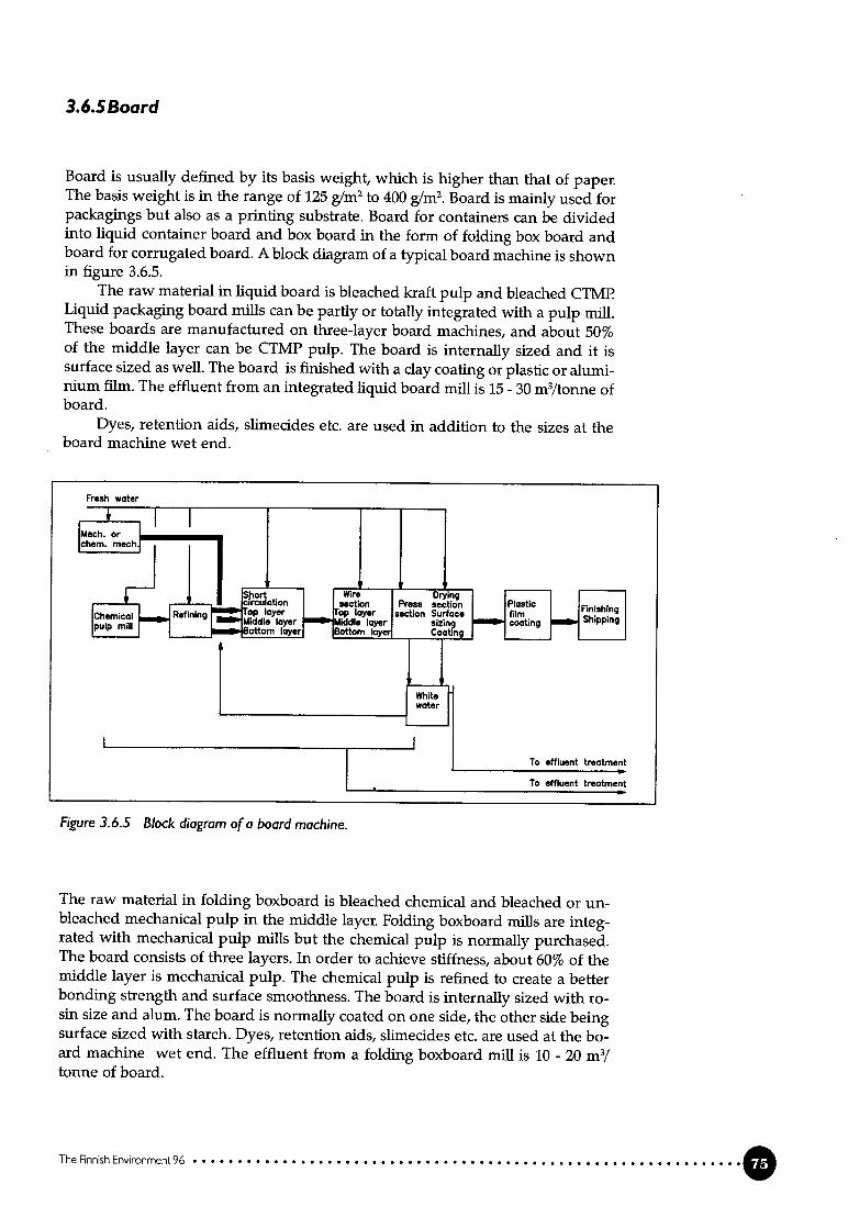
3.6.5 Board
Board is usually defined by its basis weight, which is higher than that of paper.The basis weight is in the range of 125 gIm2 to 400 g/m2.Board is mainly used forpackagings but aLso as a printing substrate. Board for containers can be dividedinto liquid container board and box board in the form of folding box board andboard for corrugated board. A block diagram of a typical board machine is shownin figure 3.6.5.
The raw material in liquid board is bleached kraft pulp and bleached CTMPLiquid packaging board mills can be partly or totally integrated with a pulp miii.These boards are manufactured on three-Iayer board machines, and about 50%of the middle layer can be CTMP pulp. The board is internally sized and it issurface sized as well. The board is finished with a clay coating or plastic or aluminium film. The effluent from an integrated liquid board mii is 15 - 30m3/tonne ofboard.
Dyes, retention aids, slimeddes etc. are used in addition to the sizes at theboard machine wet end.
The raw material in foiding boxboard is bleached chemical and bleached or unbleached mechanical pulp in the middie iayer. Folding boxboard milis are integrated with mechanical pulp mills but the chemicai pulp is normally purchased.The board consists of three iayers. In order to achieve stiffness, about 60% of themiddle layer is mechanical puip. The chemicai pulp is refined to create a betterbonding strength and surface smoothness. The board is internally sized with rosin size and alum. The board is normally coated on one side, the other side beingsurface sized with starch. Dyes, retention aids, slimecides etc. are used at the board machine wet end. The effluent from a foiding boxboard miil is 10 - 20 m3/tonne of board.
The Finnish Environment 96
Fresh water
Figure 3.6.5 Block diagram ofa board machine.
To effluent treatment
lo etf)uent reotment

The two components in corrugated board, the kraftliner and the fluting, are pro
duced in separate milis as the raw material and pulpmg process differ from each
other. The kraftliner production is normally integrated with the kraft pulp mifi.
The raw material in krafifiner is unbleached kraft pulp for the bottom layer and
bleached or unbleached kraft pulp for the top layer. No recycled fibre is used in
kraftliner production in Finland. The pulps are refined for better strength pro
perties and internally sized with rosin size. The board can be surface sized withstarch or coated. Slimecides and retention aids are used at the wet end. The effluent from a kraftliner mifi is 15-20m3/tonne of board.
In Finland the raw material in the fluting corrugated board is semi-chemical
pulp from hardwood. The board machine is integrated with the pulp miil. Norecycled fibre is used in the production of fluting in Finland. The effluent from a
fluting miil is 4 - 10 m3/tonne of board because paper machine white water isused in washing the pulp.
3.7 External treatment of discharges and emissions,solid-waste handling
In modern pulp and paper mifis a number of internal measures are taken in or
der to minimize the discharge of pollutants. Today’s technology allows, in theory,
for a complete closure of the miii’ s water system, and the breakthrough aliowing
for closed loop operation is around the corner. The combination of biological andphysico-chemical treatment methods is feasible when a wide variety of substances, as in the process water of pulp and paper milis, have to be removed from the
system in order to ensure uninterrupted production effidency and product quality.
The pulp and paper industry discharges and emits waste products in the
form of gas, liquids and solids into the air and water and for landfill. The pollu
tants in the discharges and emissions originate from the wood raw material, the
chemicals used in the process and their reaction products.Energy production is the main source of ah pollution due to flue gases from
the incineration of different fueis.The production process is a balance where ail inputs leave the process as
products, waste or energy.
3.7.! Waste water treatment
The instaliation of external waste water treatment in the Finnish pulp and paper
industry, which began in the early 1970’s, has had a significant effect on the deve
lopment of production. The impiementation of mechanical treatment reduced
the discharge of suspended solids. A minor decrease in measured COD and BOD
was noted in connection with the separation of suspended soids.
In the late 1970’s biological treatment methods were implemented in the
form of aerated lagoons in order to reduce the discharge of dissolved organic
substances. In 1984 the first activated sludge plants in the Finnish pulp and paper
industry came into operation, and today almost ali production sites are equipped
with this efficient effluent treatment system (28 plants in 1995 ). The difficulties
in operation that occurred at the beginning have been solved, and the efficiency
has been increased through greater experience.
The Finnish Environment96

Waste water treatment in aerated lagoons is in operation at three mifis in Finland(spring 1996). The average efficiency is lower than for activated sludge treatment,partly due to low operating temperatures during winter time. Anaerobic treatment is implemented at two mifis in Finland for certain waste water fractions. Inthese mifis the treated effluent fraction is combined with the remaining effluentand treated aerobically before it is discharged.
The waste water’s characteristics, which are process dependent, and the permit limits for the discharges into the recipient are the factors determining whichtreatment method/meffiods are the most suitable.
The effluent treatment implemented in the pulp and paper industry consists of primary or mechanical treatment, and secondary or biological treatment.Tertiary treatment is implemented when permit limits are exceeded or when thesecondary treatment is interrupted.
Chemical coagulation and flocculation can be used to remove residual colloidal and suspended solids either as a tertiary step, or if biological freatment isnot necessary, as an amplified primary step.
In general, effluent and water treatment produce sludge, wbich has to befurther treated and disposed of. Sludge handling is discussed in section 3.7.3.
Mechanical treatment
The first step in the effluent treatment sequence in which suspended solids (fibres, bark particles and inorganic material such as fillers) are removed is calledprimary treatment. The separation of suspended solids is generally carried outby mechanical means such as sedimentation, fiotation and ifitration.
Mechanical treatment is always used before the biological treatment of fibrecontaining effluents.
The efficiency of mechanical treatment depends on the characteristics of thewaste water and the suspended material. The separation of total suspended solids (TSS) is high, >90% . The reduction of dissolved organic substances measured as the BOD and COD are low. It is worth noting that organic suspendedsolids consume the reagent in the analysis and are therefore included in the totalCODcr . The difference in the COD number before and after the separation step isoften considerable and unfortunately misinterpreted as a real improvement ofthe water quality. The reductions in nitrogen and phosphorus vary between 0and 40%. Chemical coagulation reduces phosphorus effectively.
The sludge separated from primary treatment (primary sludge) is relativelyeasy to dewater to a 25-40% dry-solids content.
Waste water from debarking is generally treated in a separate unit for solidsremoval. Part of the treated water is recirculated. The amount of bark sludge istypically 0.5 kg dry matter/m3of wood in dry debarking and varies between 2and 8 kg/m3m wet debarking, depending on the time of year and the wood species.
Chemical treatment
The efficiency of both primary and secondary clarification is improved by theaddition of coagulants and flocculants. Chemical treatrnent is applied to ail kindsof water, from fresh to waste water. The stability of suspended particles, colloidalsand certain dissolved substances in the water is disturbed by the addition of acoagulant, generally a multivalent cation. The destabffized particles are boundinto large agglomerates using a flocculant and separated from the water by standard technology.
The Finnsh Environment 96 Q

There are three main types of chemicals used:- metaffic salts- organic polyelectrolytes- adsorbing materiais
The most commonly used metallic salts are Al-salts, but also ferric salts and
lime can be used. Organic polyelectrolytes improve the flocculation of fine par
ticles. Polyelectroiytes may be used together with coagulants to increase floc si
zes, thus making the separation more efficient.A significant removal of organic substances measured as COD can be achie
ved wiffi chemical treatment provided that the colloidal and dissolved substan
ces are affected by the coagulant or adsorbent. Simple carbohydrates and carboxylic acids are examples of substances which are not removed by chemical treatment.
Chemical treatment is used as the only treatment method in some paperand board mills in Finland and is weII suited to treating special fractions such aswaste water from coating. The chemical treatment of ail the waste water or fractions of it is in use at 13 milis in Finland.
Biological treatment
Biological treatment utilizes the natural biological process, where micro-organisms
use dissolved organic material in the water as a source of energy. In biological
treatment the biodegradable dissolved and colloidal organic substances are frans
formed partly into a solid cell substance and partly into methane, carbon dioxide
and water (anaerobic) or into carbon dioxide and water only (aerobic). The bios
ludge is separated before the water is discharged.The micro-organisms need nitrogen and phosphorus for proper growth. In
pulp and paper miii effluents the amount of nutrients is low compared with the
amount of organic substances. It is, therefore, necessary to add phosphorus and
nitrogen to the waste water to achieve efficient treatment. Waste water from the
production of bleached kraft pulp usually contains enough phosphorus, and only
nitrogen is added.The waste water is neutralized pnor to biotreatment by using CaO, Ca(OH)2,
NaOH or H2S04.The temperature of the waste water influences the functioning of the biolo
gy. The temperature must not exceed 30-35° C in aerobic processes and cooling
can become necessary. Temperatures below 20° C should be avoided as the bio
activity decreases considerably.Lignin, which is dissolved during the pulping and is, to some extent, pre
sentin the effluent, is only partially degraded in biological treatment. The remai
ning lignin fractions give the treated water a brown colour at a neutral pH.
Two main types of biological treatment are used:- aerobic treatment with micro-organisms requiring oxygen
- anaerobic treatment with micro-organisms requiring an oxygen-free envi
ronment
Aerobic treatmentThe aerobic tTeatment methods that are in use in the pulp and paper industry in
Finland are activated siudge (AS) and aerated lagoon (AL). AS treatment has
been installed m most of the pulp and paper miils. AL treatment is used at three
milis, one of which is now instaffing activated sludge treatment (1996).
A scheme for activated sludge treatment, in principle, is shown in figure
3.7.1
0 The Finnish Envwonment 96

5
1 Effluent inlet 5 Outlet2 Primary clarification 6 Return sludge3 Aeration 7 Excess sludge4 Secondary clarification
The reduction of easily degradable organic material measured as the BOD7 isvery fast in AS treatment due to the high concentration of micro-organisms. TheBOD load and the hydraulic load can, therefore, he kept high. The sludge generation in activated sludge treatment is relatively high (0.4-0.7 kg DS/kg BOD-reduced) because approximately 40-50% of the organic carbon is converted into biosludge. The retention time is relatively short (10-24 h), and no minerallzation ofbiosludge occurs as in aerated lagoon treatment. For the best possible resuit theaddition of nitrogen and phosphorus is necessary. The addition of nutrients iscontrolled in proportion to the amount of biodegradable substances in the irilet,which is estimated by the BOD analysis. Overdosing is avoided by monitoringthe concentration of the nutrients in the outlet.
The efficiency of the treatment varies, depending on the type of effluent.Typical reduction rates in kraft pulp effluents and paper miii effluents are showniri table 3.7.1 and table 3.7.2.
In AL treatment the biosludge production is relatively low (0.1-0.3 kg DS/kgBOD-reduced). The reduction of organic substances is lower than in AS treatment (table 3.7.1 and 3.7.2). In the summer the reduction rate is moderate, but inthe winter when the temperature drops in the lagoon the efficiency decreasesbecause of the low outside temperature and the long retention time in the lagoon(3-10 days).
The Finneh Enronment 96
7
Figure 3.7.! Activated sludge treatment plant.
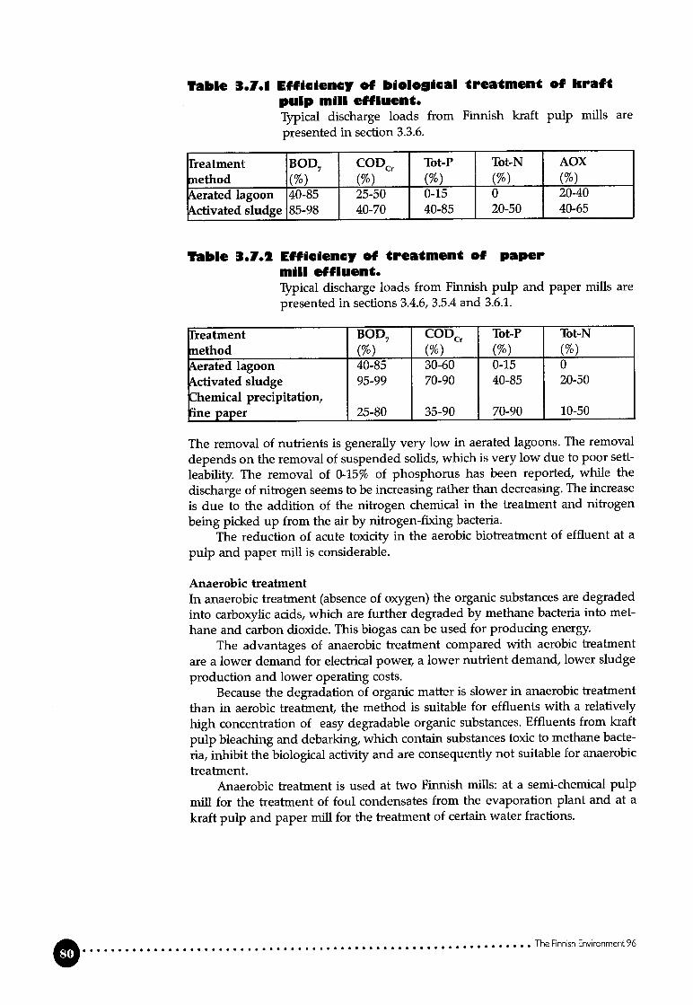
Table 3.1.1 Efficiency of bioioical frcatment of kraftpuip miii effluent.Typical discharge loads from Finnish kraft pulp milis are
presented in secfion 3.3.6.
Efficiency of reatment ofmiii effiuent.Typical discharge loads from Finnishpresented in sections 3.4.6, 3.5.4 and 3.6.1.
rreatment BOD7 CODCr Tot-P Tot-Nnethod (%) (%) (%) (%)erated lagoon 40-85 30-60 0-15 0ctivated sludge 95-99 70-90 40-85 20-50Ienilcal precipitation,jne paper 25-80 35-90 70-90 10-50
The removal of nutrients is generally very low in aerated lagoons. The removal
depends on the removal of suspended solids, which is very low due to poor sett
leability. The removal of 0-15% of phosphorus has been reported, while the
discharge of nitrogen seems to be increasing rather than decreasing. The increase
is due to the addition of the nitrogen chemical in the treatment and nitrogen
being picked up from the air by nitrogen-fixing bacteria.The reduction of acute toxicity in the aerobic biotreatnient of effluent at a
pulp and paper miil is considerable.
Anaerobic treatmentIn anaerobic treatinent (absence of oxygen) the organic substances are degraded
into carboxylic acids, which are further degraded by methane bacteria into met
hane and carbon dioxide. This biogas can be used for producing energy.
The advantages of anaerobic treatment compared with aerobic treatment
are a lower demand for electrical power, a lower nutrient demand, lower sludge
production and lower operating costs.Because the degradation of organic mafter is slower in anaerobic treatment
than in aerobic treatment, the method is suitable for effluents with a relatively
high concentration of easy degradable organic substances. Effluents from kraft
pulp bleaching and debarking, which contain substances toxic to methane bacte
ria, inhibit the biological activity and are consequently not suitabte for anaerobic
treatment.Anaerobic treatment is used at two Finnish mills: at a semi-chemical pulp
mii for the treatment of foul condensates from the evaporation plant and at a
kraft pulp and paper miii for the treatment of certain water fractions.
TheFinnishEnvronrnent96
?able 3.1.1 paper
pulp and paper mifis are

Other treatment methods
Contaminated water can be treated by ifitration. Filtration is applied to a widevariety of water. Decreasing the size of holes or pores in the filtermg mediummakes the separation of suspended solids more effective. The application of tightfilter mediums enabies parficles the size of an atom to be separated. The tighterthe medium, the higher the pressure needed to force the water through and thesmaller the flow for a given area.
Membrane fiitration and ultrafiltration are methods where water contaimngsuspended impurities is forced to pass through a membrane with very small holes. The method is used for the recovery of expensive pigments and polymericsubstances with a high molecular weight.
One paper miii uses membrane ifitration for the treatment of white waterthat is put to further use in showers, and another for coating effluents. Thecoating components are reused.
A recently implemented treatment is evaporation, also known as distullation.As it applies low pressure, the energy consumption is moderate.
Sludge handling
Mechanical, biological and chemical water treatment generate sludge that is separated by sedimentation, fiotation or filtration. The dry-solids content of the separated sludge is very low (1-3%). The sludge has to be dewatered before it canbe disposed of. Sludge handllng is dealt with in greater detail in section 3.7.3.
Energy consumption
External treatment normally consumes energy. Anaerobic treatment is an exception if the energy content in the generated biogas is recovered by burning.
The consumption of electrical energy in activated sludge treatment is in therange of 1.2-2 kWh!kg of reduced BOD (aeration and pumping), which is theequivalent of 1 -1.5 kWh/ m3.
The energy consumed in ifitration is dependent on the drop in pressureacross the medium. For example, the ultraffltration of coating waste water consumes 3-5 kWh/m3.
Evaporation at low pressure using mechanized vapour recompression consumes 5 - 15 kWh/m3.
Typical energy consumption figures are presented in figure 3.7.3.
Table 3.1.3 Typical power consumption for differenwas(c watcr treatment methods.
Type of miii Power- treatment method consumption
(kWh/t of product)Bleached kraft- mechanicai treatment 3- activated sludge 46Paper miii- mechanical treatment 1.5- activated sludge 15
The Finnish Environment 96 0

3.7.2 Treatment ofemissions into the air
The emissions into the air from the production processes and energy production
are externafly treated. Today the emissions from the point sources (recovery boi
ler, Ilme kiln and auxiliary boilers) are relatively low due to the effectiveness of
both the process control and the internal measures and external treatment. The
reduction in the diifuse emissions of reduced sulphur compounds is stili a chal
lenge at some kraft pulp milis.The air pollutants that are removed by external treatinent are in most cases
separated as solid waste (dust) or absorbed in a washing solution ( dust, sulphur
and chlorine compounds). The separated flow is returned to the process (kraftpulp) or disposed of. Increasingly stringent environmental protection requirements and more closed process water systems are resulting in increased difficulties in managing the sodium-sulphur balance in the kraft pulp process. Sulphuraccumulates in the process, as does sodium at some kraft pulp milis. Excess sulphurresults in increased sulphidity in the cooking liquor, which affect the quality ofthe pulp. The recirculation of the used washing solution into the process resultsin an increased load of inert inorganic material and an increased consumption ofalkali.
At a kraft pulp mii most of the dust is emitted with flue gases from the reco
very boiler, the lime kiln and the bark boiler.The emission of dust from the recovery boiler is reduced in two stages. In
the first stage the main part of the fly ash is removed from the flue gases in ash
pits. The second stage is the electrostatic precipitator. The separated ash is taken
to the black liquor. Ali the recovery boilers in Finland are equipped with electrostatic precipitators. The reduction of suspended particles is over 99% and the
concentration in the flue gases is normally 50-200 mg/m3n (0.1-0.7 kg/ADt).The dust emitted from the lime kun is generated by two main mechanisms.
One part of the ilme mud is not transformed into calcium oxide, which results in
dust being formed. The other mechanism is vaporization of the sodium that is
present due to poor washing of the lime mud. To control these emissions the flue
gases from the lime kiln are treated in an electrostatic precipitator and/or a was
her. The emission concentration is 20-300 mg/m3n(<0.1-0.3 kg/ADt). The separated dust is normally returned to the lime mud system, but occasionally it has to be
discarded as solid waste.The emission of dust from power plant boilers is controlled most effectively
with electrostatic precipitators. The concentration of TSP (total suspended parti
culates) can he reduced to less than 50 mg/m3nand for some boilers the emissioncan even be beiow 10 mg/m3n. The combustion of coal tends to lead to largeremissions of dust than the combustion of other fueis. This has to he considered in
the design of the electrostatic precipitator.The emission of chlorine compounds in vent gases from the bleaching of
kraft pulp and chlorine dioxide generation is controlled initially by managing the
process efficiently and then, if necessary, reduced further in a washer with sulphur
dioxide solution being used as the absorption liquor. Typical emissions of chlorine
compounds into the air are 0.05-0.3 kg Ci/ADt pulp.Nitrogen oxides are formed during the combustion of the nitrogen in the
fuel and by thermai oxidation of the combustion air. The formation of thermal
NOx is low under normal circumstances. The reduction of the NOx emission
from a boiler can, to some extent, be controlled by the distribution of the combus
tion ait This measure has aiready been implemented in kraft pulp recovery boi
lers in Finland. The formation of thermal NOx is smaller in the recovery boiler
0 The Finnish Environment 96

and the ilme kiln than in power plants in general due to the lower combustiontemperature. Typical emissions from the recovery boiler are 150-250 mg NOJm3n(0.8-1.3 kg NOJADtI < 100 mg NOJMJ) and from the lime kiln 250-400 mg NOJm3n (02-0.3 kg NOJADt, 150-200 mg NOJMJ). The emission of NO from generalbark boilers is relatively low (100-300 mg NOJMJ) compared with the emissionfrom coal fired boilers (300-500 mg NOJMJ).
If the emission of sulphur dioxide is not reduced enough by internal measures or by changing to a low-sulphur fuel, a desulphurization method has to beadopted. The most common method is based on absorption in an alkaline solution. The reduction of S02 varies between 80 and over 95%, depending on whatalkali is used. The highest reduction rates are reached with a soluble alkali suchas sodium hydroxide or carbonate.
Most of the recovery boilers are equipped with scrubbers to reduce the S02content of the flue gases. In mifis tilat burn black liquor with a high dry-solidsconcentration (>75% DS) the emission of S02with the flue gases is very low (practicaily zero) and the use of a scrubber is not as essential as for recovery boilers thathum black liquor with a lower dry-solids concentration (65-70%).
The scrubber is normaily divided into three zones: the chloride zone,washing zone and heat recovery zone. In the chloride zone chloride is absorbedin cold water and in the washing zone S02 and dust are removed. H2S is alsoremoved. The reduction of the S02 emission is about 90%. In the heat recoveryzone hot water is produced for e.g. pulp washing in the bleaching plant.
Typical emissions of S02 from a recovery boiler equipped with a scrubber are0.05-0.3 kg S/ADt.
The sulphur dioxide in ilme kUn flue gases originates from the fuel and fromthe malodorous gases if these are burnt in the ilme kiln. The binding of sulphurto calcium oxide is Iimited. Sodium carbonate is more effective for binding sulphur.This is, however, only an impurity resulting from poor washing of the lime mudand the binding is, therefore, limited. The emission of sulphur dioxide can becontroiled by sulphur coming into the ilme kiln or the recovery of sulphur in aflue gas scrubber. The emission of sulphur is highly dependent on the handlingsystem for strong malodorous gases. It can be kept relatively low if strong malodorous gases are not burnt in the lime kun (<0.05 kg S/ADt) or, if they are burntin the ilme kiln, by instaffing a scrubber (0.1-0.3 kg S/ADt). The sulphur content ofthe strong malodorous gases can be reduced by washing with oxidized whiteliquor before burnrng.
The amount of reduced sulphur compounds formed in and emitted fromthe kraft pulp process is influenced by several internal process conditions (combustion conditions, sulphidity, heat treatment of black liquor, lime mud wash etc.).The handling of malodorous gases is discussed in section 3.3.1.
Air pollution prevention measures increase the energy consumption to arelatively moderate extent.
3.7.3Handling of solid waste
Solid waste is a matenal or an object that is removed from use and disposed of.Bark and wood residues from woodhandling should be considered as waste onlywhen they go for permanent landfuliing. Sludge from waste water treatment isburnt and the energy content is recovered, leaving ash as a solid waste.
The Rnnish Enrment 96 O

The Finnish pulp and paper industry has 46 landfffls of its own (1994). Over 90%
of solid process waste is transported to these Iandfffls. The waste transported for
landfill consists of wood and bark residues, ashes, ilme mud, dregs from causti
cizing, rejects, fiiler and latex waste, coating waste, waste water treatment sludge,
plastics, scrap and building waste.In 1995 the Finnish pulp and paper industry disposed of 220,000 tonnes of
ashes, 150,000 tonnes of waste water treatment sludge, 56,000 tonnes of fihre and
coating sludge, 45,000 tonnes of deinking sludge and 47,000 tonnes of waste wood
at Iandfill sites. The waste quantities are given as dry solids.
Sludge from waste water treatment is one of the main groups of solid waste.A large amount of sludge is generated in primary treatment and in biological
treatment with the activated sludge method. Aerated lagoons generate only smail
amounts of excess sludge. The generation of sludge in anaerobic treatment is also
moderate. Chemical flocculation generates a considerabie amount of sludge. Demking sludge from the processing of recycled fibre is often handled together with
sludge from effluent treatment.Biological and chemical sludges have poor dewatering properties. Normally
they are mixed with primary sludge and bark sludge before dewatering.The sludge is usually thickened before being dewatered in a filter press,
screw press or on a vacuum filter.Inorganic and/or organic chemicals are used to improve the dewatering of
sludge by forming larger flocs. Mixed sludge can he dewatered to a 25-35% dry
ness with filter presses and to 40-50% with a screw press using steam in the pre
treatment stage.In Finland dewatered sludge is burnt or sent to a Iandfffl (60:40). In sludge
burning the net energy production is about zero or negative, if the dry-solids
content m the sludge is below 40% and if the sludge contains a high amount of
inorganic material. To maintain good burning conditions the use of auxiliary fuel
is necessary. If the sludge is mixed with bark and other wood waste material no
auxffiary fuel is generaily needed. Burning reduces the quantity of waste consi
derably. The inorganic content remains as ash, which is normally transported to a
landfill site. For sludge with a low net heat value landfilling can be a better alter
native than burning as far as air emissions are concerned. For a paper muU ma
king coated paper grades the ash content of the primary sludge can be 35-60%.Chemical sludge cannot be incinerated alone without the use of auxiliary
fuel because of the high content of inorganic matter and water. The sludge is,
therefore, normally transported to a landfill site. Sludge from flocculation with
only synthetic organic polyelectrolytes is mostly incinerated.In the Finnish pulp and paper industry about 60% of the generated waste
water treatment sludge is burnt, normally together with bark in a bark boiler.
Burning in a fluidized bed furnace with other solid fueis is common practice.
One kraft pulp muU mixes biosludge and another fiotation foam from resin remo
vai with the biack liquor and burns it in the recovery boiler.One muU incinerates deinking sludge, but the other three mifis producing
deinked pulp dispose of the sludge at a landfffl site.The amount of soild waste for landfill is considerably reduced by sludge
burning, but there is stiil a large amount of ash that has to he disposed of.
Most of the ash going for landifil is furnace ash and fly ash from the produc
tion of energy in auxiliary boilers.Most of the generated ash (65%) is transported to a landfffl site. Boiler ash
can be used in cement and concrete and as a soil conditioner. The ashes reduce
the acidity in the soil because of their high allcalinityIn 1995 about 2,000 tonnes of hazardous waste were transported to a special
waste disposal plant for destruction or returned to the manufacturer for reuse.
0 The Finnish Enronrnent 96
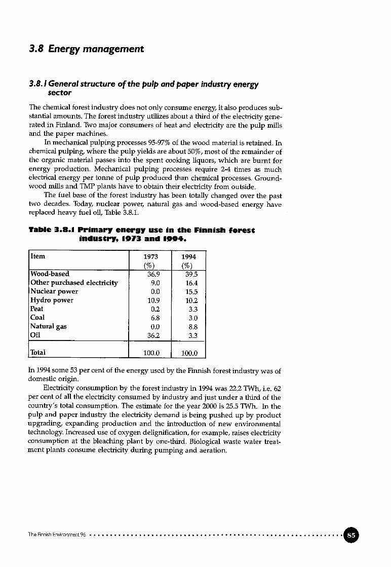
3.8 Energy management
3.8.! General structure of the pulp and paper industry energysector
The chemical forest industry does not only consume energy, it also produces substanfial amounts. The forest industry utilizes about a third of the electricity generated in Finland. Two major consumers of heat and electricity are the pulp mifisand the paper machines.
In mechanical pulping processes 95-97% of the wood material is retained. Inchemical pulping, where the pulp yields are about 50%, most of the remainder ofthe organic material passes into the spent cooking liquors, which are burnt forenergy production. Mechanical pulping processes require 2-4 times as muchelectrical energy per tonne of pulp produced than chemical processes. Groundwood milis and TMP plants have to obtain their electricity from outside.
The fuel base of the forest indusfry has been totally changed over the pasttwo decades. Today, nuclear power, natural gas and wood-based energy havereplaced heavy fuel oil, Table 3.8.1.
Table 3.8.1 Primary eneruy use in the Finnish forestindustry, 1973 and 1994.
Item 1973 1994(%) (%)
Wood-based 36.9 39.5Other purchased electricity 9.0 16.4Nuclear power 0.0 15.5Hydro power 10.9 10.2Peat 0.2 3.3Coal 6.8 3.0Natural gas 0.0 8.8Oil 36.2 3.3
Total 100.0 100.0
In 1994 some 53 per cent of the eriergy used by the Finnish forest industry was ofdomestic origin.
Electricity consumption by the forest industry iii 1994 was 22.2 TWh, i.e. 62per cent of ail the electricity consumed by industry and just under a third of thecountTy’s total consumption. The estimate for the year 2000 is 25.5 TWh. In thepulp and paper industry the electricity demand is being pushed up by productupgrading, expanding production and the infroduction of new environmentaltechnology. Increased use of oxygen delignification, for example, raises elecfficityconsumption at the bleaching plant by one-third. Biological waste water treatment plants consume electricity during pumping and aeration.
The Finnish Enironmerit96

3.8.2Specific characteristics of the pulp and paper industry energysector
Examples of energy consumption in the production of pulp and paper are pre
sented in table 3.8.2. These values represent the use of modern technology under
Finnish circumstances.
Tabio 3.8.2 Computed typical specific net eneryconsumptdon by pulp and paper milisappIyin modern technoIoy (pulpproduction included for paper rades) (ref.Kestävä paperi-research programme)
Heat Electricity TotalProduct [GJ/tJ [MWh/t [MWh/tJMF newsprint (100% TMP) -1.33 2.19 1.82SC-magazine (100% TMP) -0.25 2.06 1.99LWC-magazine 0.40 2.19 2.30Fine paper 4.72 0.53 1.84Coated fine paper 4.76 0.79 2.11
Coated box board 4.61 0.86 2.14Bleached hard wood kraft 0.12 -0.33 -0.30Bleached soft wood kraft -0.88 -0.38 -0.62
(- ) indicates ä surpius -
In 1994 the total energy consumption in the Finnish forest industry was 360 PJ.
Of the fuel used about two-thirds are renewable fueis (black liquor and wood
waste). The annual total consumption of electrical energy is about 20 TWh (1994,
22.2 TWh). The production of mechanical pulp consumes about 8 TWh/a and the
production of paper and board about 7 TWh/a. The manufacturing of chemical
pulp consumes about 5 TWh/a. On the other hand, kraft pulp mills produce about
6 TWh/a of electrical power. So the chemical pulping plants are self-sufficient in
electrical energy.One characteristic of the energy-intensive forest industry is the production
of electrical power in back-pressure power plants directly connected to the pro
duction processes. About one-third of the total electrical energy is back-pressure
power (table 3.8.3). The energy content of the fuel is very efficiently utilized in a
back-pressure power plant. The high-pressure, superheated steam generated in
the boiler is utilized for power generation in the back-pressure turbine, and the
steam leaving the turbine at a Iower pressure is utilized in the process as heat
energy. The ratio of electrical effect/heat effect is, usually, 0.2-0.3.
Tabio 3.8.3 Supply of electrical power for the Finnishforest industry.
Electrical power (GWh)1991 1992
Back-pressure power 5,943 6,080Nuclear power 5,479 5,490
Hydro power 4,034 4,650
Condensing power 2,707 1,970
Purchased electrical power 848 1,100Gas turbine 45 90
Total 19,056 19,380
0 The finnish Enwonmenz96

The total energy consumption in the Finnish forest industry is presented in table3.8.4.
Table 3.8.4 Total enery consumption in the Finnishforest industry.
Item 1991 1994(PJ) (Pfl
Peat 11.2 11.9Wood-based fuel 113.4 142.8Oil 11.3 10.8Natural gas 28.8 31.8Coal 14.2 11.9Own nuclear power 55.6 56.0Own hydro power 41.0 36.6External electrical pnwer 36.1 59.3Total 311.6 361.1Fuel, total 179 209Wood-based fuel, share of total, (%) 36 40Peat, share of total, (%) 4 3Consumption of electrical power, (TWh) 19.1 22.2
In kraft pulping biofueis are generated as by-products. These are bark and woodresidues from wood handling and black liquor ftom cooking. These biofueis areused initiallyto cover the energy demand and, if they are not sufficient, the shortage is covered with steam produced from purchased fuel. In a modern kraftpulp miii the heat energy production from the recovered bark and black liquorexceeds the energy demand. Fossilized fueis are used mainly as support fuel. Thetraditional use of oil in the lime kiln has decreased substantially.
The conventional power plant configuration in a non-integrated kraft pulpmiii is a recovery boiler and a bark boiler feeding a back-pressure turbine withintermediate steam tapping and, possibly, condensing. Malodorous gases are collected and burnt, mainly for environmental protection reasons as there is no/littlenet energy generation.
In an integrated pulp and paper mifi the excess heat produced by the pulpmiii is not quite enough to cover the energy consumption of the paper production. The additional demand for heat has to be produced in woodjbark boilersand auxffiary boilers. Fossffized fuel is used as support fuel in bark and sludgeboilers and as the main ftiel in auxiliary boilers. The fueis used in the powerstations at paper milis are mainly fossil fueis, especially in non-integrated papermills.
Peaks in energy consumption are often satisfied by using a small boiler forfossil fuel. CHP (combined heat power) plants based on gas turbine in combination with a steam boiler and steam turbine are very efficient and a few instailations have been made.
Nowadays some Finnish paper and pulp milis have made energy supplyagreements with energy production companies. This allows the miii organizafion to concentrate, technically and financiaily, on its core business. These newpower plants are owned and maintained or only operated and maintained bythe energy supplier.
The emissions from power production are dependent on the fuel, the fuelmixture and the unpurities content. 011 and coal contain sulphur but natural gasdoes not.
The Finnish Environment 96 O

A noticeable factor concerning the total discharges from the pulp and paper in
dustry in Finland is the large share of bark used as power plant fuel. As bark does
not contain sulphur, there wil be no sulphur dioxide emissions, and the emission
of nitrogen oxides wffl also be lower than in the burning of other kinds of fuel
due to the low combustion temperature. When bark is being burnt together with
fueis that contain sulphur, the alkaline bark ash binds some of the sulphur and
thus reduces the discharge. This cannot be fully utilized, because at paper mifis
which predominantly consume fossil fueis the generation of bark waste is gene
rally small.
3.8.3BoiIers used in energy production
Recovery boiler
A recovery boiler is essential for producing energy at a kraft pulp muU. The recovery boiler acts as a back-pressure power station where the black liquor separated in the pulping process is burnt. The cooking chemicals are recovered as asmelt from the bottom of the boiler and the heat generated is utilized for thegeneration of high-pressure, superheated steam. Part of the energy content in
the high- pressure, superheated steam is utffized for generating power in a backpressure turbine. Medium- pressure steam (1.0-1.3 MPa) extracted from the turbi
ne and low-pressure exit steam (0.3-0.4 MPa) are utilized for covering the heat
energy demand in the kraft pulp process.Process modifications (e.g. extended delignification, oxygen delignification,
water system close up) alter the properties of the black liquor. The development
of black liquor properties is presented m table 3.8.5.
Table 3.8.5 Properties of black Iiquor
Black liquor 1982 1992 2002estimate
Dry-solid content [tDS/ADt pulpi 1,700 1,680 1,840Dry-solid content [% 64 72 80Calorific value, low [GJ/ADt] 15 13.9 13
Steam boilerHigh-pressure steam for electrical power is normally produced at a paper or
board muU. The low- pressure steam after the turbo generator is condensed on the
paper machine to dry the product. The fueis used in the boilers are coal, peat,
wood waste in the form of bark and fibrous sludge from effluent treatment.
Most of the coal and wood-waste boilers are circulafing or fluidized bed boi
lers. These boilers offer the opportunity to use a wider range of fueis and give off
lower emissions from the burning of peat and biofueis than the oider grate boi
lers.Fluidized bed combustion was developed in the 1970’s especially for diffi
cult fueis with a low heat content and widely varying properties such as wood
waste, peat, water treatment sludges as well as other industry and municipal
waste.High efficiency, low emissions, mixed fueis and a flexibility in different load
situations are typical characteristics of fluidized bed combustion, which is the only
practical way of burning sludges and other waste with high water content.
Although the combustion temperature is relatively low (800-950° C), the combus
0 The finnish Environment 96

tion efficiency is high due to the very effective mixing of the materiais and heattransfer between the soild material and the flue gases. The formation of thermalNO is low and the NO emissions are relatively low due to the low combustiontemperature. If the fuel contains sulphur, sulphur emissions can be prevented bythe addition of ilme to the bed. At temperatures below 9000 C sulphur reacts withlime or calcium in the bark and the sulphur dioxide emissions are reduced considerably.
Combined heat power plants (CHP)By utilizing gaseous fuel, like natural gas, it is possible to combine a gas turbogenerator with a steam turbo-generator and produce more electricity than heat.Combined heat power plants consist of a gas turbine, a steam boiler and a steamturbine. CHP plants are used when the need for electrical energy at a paper mifiis high. The electrical effectjheat effect ratio is usually 0.8-0.9. Lately several newCHP plants have been installed by the Finnish forest indusfry.
3.9 Monitoring of discharges and emissions into waterand the air, enWronmental management
Monitoring requirements are determined by the information required by the authorities and by the process control.
The statutory monitoring of discharges and emissions from Finnish industryand the effects of the emissions on the environment is based either on the Court’sor municipal authority’s decision or the statement given by the Regional Environment Centre. The monitoring is based on self-monitoring and it is carried outaccording to a programme approved by the authority. The monitoring programme is drawn up specifically for each milj. The monitoring programmes, monitoring results as well as the effluent and recipient monitoring reports are availableto the public. The results of monitoring emissions are regularly reported (once amonth, four times a year, once a year) and, furthermore, each mifi is obliged tosubmit an annual report to the authorities. Ali the monitoring results are comparable within Finland.
Important factors connected with the monitoring of discharges and emissions are the flow measurement, sampling method, handling and storing of samples, analysis method and accuracy, and the calculation and reporting of the results.
It is most important to note that great care has to be taken when a comparison is made with the discharge and emission figures in reports ftom differentcountries. Variations in the methods of sampling, pre-treatment and analysis ofthe sample, calculational and reporting practices make it difficult to interpret correctly.
3.9.1 Discharges into water
Normaily there are no instructions about how to measure the flow in the monitoring programme.
The milis choose the flow-measurement method themselves. The appliedmethods for waste water vary from open systems (e.g. Venturi fiumes) to magnetic flow meters.
The Rnnish Envronment 96 O
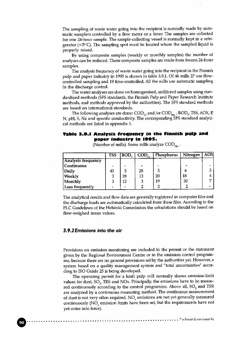
The sampling of waste water going into the recipient is normally made by auto
matic samplers controlled by a flow meter or a timer. The sampies are collected
for one 24-hour sample. The sample-collecting vessel is normally kept in a refri
gerator (<5° C). The sampling spot must be located where the sampled liquid is
properly mixed.By using composite sampies (weekly or monthly sampies) the number of
analyses can be reduced. These composite sampies are made from frozen 24-hour
sampies.The analysis frequency of waste water going into the recipient in the Finnish
pulp and paper industry in 1995 is shown in table 3.9.1. Of 46 mifis 27 use flowcontrolled sampling and 19 time-controlled. Ali the mifis use automatic sampling
in the discharge control.The water analyses are done on homogenised, unffltered sampies using stan
dardized methods (SFS standards, the Finnish Pulp and Paper Research Institutemethods, and methods approved by the authorities). The SFS standard methods
are based on international standards.The following analyses are done: CODCr and /or CODMfl, BOD7,TSS, AOX, P,
N, pH, S, Na and specific conductivity. The corresponding SFS standard analytical methods are listed in appendix 1.
Table 3.0.1 Analysis frequency an the Finnish pulp andpaper industry in 1005.(Number of mills). Some mifis analyze CODMfl.
TSS BOD7 CODcr Phosphorus Nitrogen AO)
Analysis frequency —
Continuous - - - - - -
Daily 41 5 28 5 6 3
Weekly 2 28 13 20 18 4
Monthly 3 12 3 19 20 7Less frequently - - 2 2 2 -
The analytical results and flow data are generally registered in computer files and
the discharge loads are automatically calculated from these files. According to thePLC Guidelines of the Helsinki Commission the calculations should be based on
flow-weighed mean values.
3.9.2Emissions into the air
Provisions on emission monitoring are included in the permit or the statement
given by the Regional Environment Centre or in the emission control program
me, because there are no general provisions set by the authorities yet. However, a
system based on a quality management system and “total uncertainties” accor
ding to ISO Guide 25 is being developed.The operating permit for a kraft pulp mifi normaily shows emission-limit
values for dust, S02, TRS and NOx. Principally, the emissions have to be measu
red continuously according to the control programme. Above ail, S02 and TSR
are analyzed by a continuous measuring method. The continuous measurement
of dust is not very often required. NO emissions are not yet generally measured
continuously (NOX emission limits have been set, but the requirements have not
yet come into force).
0 The Finnish Environment 96

General requirements for continuous monitoring systems are that the samplingplaces should be representative and that the monitoring equipment should besuitable for the concentrations to be monitored and the prevailing circumstances.The emission-control data system should preferably be part of the process controlsystem.
The continuous measurement system is generally validated by an authorized laboratory or a laboratory accepted by the authorities.
In Finland emission limit values are set per energy input for boilers (mgpollutanl/MJ) or per tonne of the end product (kg pollutant/torme product). It is,therefore, necessary to measure the concentration as well as the gas flow.
Because of the water content, solid particles and aggressive substances inthe flue gas there can be a probiem in taking a representative sample of the fluegas into the measuring instrument. Before the analysis, solid particles are removed by fflters and moisture is removed by condensing. There are several methodsfor removing the moisture without at the same time removing the componentsthat are to be analyzed. One solution is to dilute the gas (20-40 times) with dryand clean air so that the moisture content no longer interferes with the analysis.This method is often used in Finland. Experiences with methods where the sampleis dried have mostly been negative in Finnish mifis, especially in cases wheresulphur concentrations are low and the sample contains particulate matter.
Different pollutants require different kinds of control and monitoring strategies. In a kraft pulp miii dust and NOx are emitted from a few sources and it is,therefore, easy to decide where to measure and what kind of system to use.
Monitoring the total emissions of TRS and S02 is more complicated. Sulphurcompounds are discharged into the air from different sources such as the recovery boiler, lime kun, burner of malodorous gases and diffuse sources. At some mifisthe emission of S02 is predominant, while at others mills it is the TRS emission.The diifuse emissions of sulphur represent a large part of the total sulphur emission. In order to monitor the total sulphur emission it is necessary to carry outmeasuring campaigns that cover the whole miii to determine the most importantemission sources and what compounds dominate the total emission. The assessment of these results and a sulphur balance calculation are the basis for the decision concerning where continuous measurements are necessary and what kindof analyzer should be used and, on the other hand, where periodical measurements are valid.
3.9.3Environmental mancigement systems
The environmental management systems for the Finnish chemical forest industryare based on the BS 7750 and the ISO 9000 and ISO 14000 series standards, andthey are usually linked to the quality systems of the company concerned. Theeffectiveness of the system is ensured by regular reviews and audits aiming at thecontinuous improvement of environmental protection practices.
In 1995 the first environmental management systems complying with the BS7750 standard were certified at five milis. Seven mufis incorporated environmentai protection into their ISO 9000 series quality systems, in addition to the threemilis which had aiready done so.
Environmental management systems in accordance with the ISO 14000 se-ties are being developed at 15 mifis (beginning of 1996).Two mifis announced thatthey wffl develop their systems to comply with the EU regulation on environmental management and auditing, EMAS.
The Finnish Envronment 96 0

Rcference MilisO..OOOO...OOOO.OOOOOOOOOOOOOOOOOOOOOOOOOOOOOOOOOOOOOOO
The reference mifis are Finnish mifis that where visited in 1996 for review of the
operation and interviews with the personnel.
4.! Newsprint
4.1.1 General
The mifi produces newsprint and other wood-containing papers on three paper
machines.In 1995 the total production of paper was 500,000 tons, 370,000 tonnes of
which was newsprint and the rest SC magazine printing paper.The mechanical pulp for newsprint is produced at TMP plant no. 2. The rest
of the mechanical pulp is produced at TMP plant no.1 and two groundwood
plants. The wood raw material is Norwegian spruce. Round wood logs are debar
ked and chipped on two debarking lines. The newsprint at PM3 is produced en
tirely from TMP without any kraft pulp or filler. For the other paper grades pro
duced the miii uses SGW and kraft pulp purchased from Finnish mifis and filler
clay.The miii is located inland by a river. The mifi takes fresh water from the river
and discharges treated effluent and warm cooling water back into the river. To
gether with the municipahty the mii owns an energy production company ope
rating a big solid waste and biofuel boiler.
4.1.2 Debarking
Spruce logs are debarked on site. The total use of wood in 1995 was 1,170,000 m3,
about 250,000 m3 of which was purchased from sawmffls as chips. The debarking
is wet. Water is pumped into the drums, and water helps to remove bark through
the bark chutes. The bark is pressed and sold to the energy company for fuel.
Warm clear ifitrate from the paper miii is used as the process make-up water.
In the winter time the filtrate is further heated with excess energy ftom the pul
ping deparbnent. Circulating water in the debarking plant is clarified. Sludge is
pumped into the mill’s sludge dewatering plant. Part of the overflow is taken to
the biological treatment plant. The effluent data is shown in table 4.1.1.
0 The Finnish Environment 96

Table 4.1.1 CIarfied debarkin9 effluent.
The miii is currently modernizing the debarking plant. De-icing wffl be done on ade-icing conveyor with steam. The COD load from debarking is expected to decrease by 20% before the effluent treatment plant. The debarking wffl be dry andthe effluent flow is expected to be about 0.2 m3per m3 of wood.
4.! .3Stock preparation for newsprint production (PM3)
The TMP line (TMP2) produces pulp for PM3. The plant includes three two-stagerefiner lines (totaffing 83 MW of motor power). In 1995 the production was about180,000 tonnes of pulp. The newsprint production of PM3 was 203,000 tonnes in1995. The rest of the mechanical pulp was taken from the other TMP line andftom the groundwood lines. The refined TMP is screened before it is stored at aconsistency of about 4%. Rejects from screening are refined in reject refiners (4MW each). The freeness of the pulp is 100 to 110 ml CSE The pulp can be bleached with dithionite, if needed.
TMP2’s energy consumption is about 2.5 MWIiIt of pulp, 1.05 MWIVt (about40%) of which is recovered as steam. The recovered heat energy is used for paperdrying and represents about 65% of the steam used for newsprint drying at PM3.
The process water used on the TMP2 line is filtered white water from PM3.The only effluent discharged from the TMP2 line ts about 10 l/s from chipwashing.
4.I.4Paper machine PM3
PM3 produces newsprint from TMP and some groundwood pulp. No chemicalpulp or fuller clay are used. The production in 1995 was 203,000 tonnes. PM3 doesnot have a size press and the paper is finished by an on-machine calender. Thepaper is then rewound and packed.
Retention chemicals, dyes and some slimecides are used at the wet end ofPM3.
PM3 consumes about 13 m3 of mechanically treated fresh water/ tonne ofpaper and together with the TMP2 line about 14 m3/ton of paper. The water ismainly used in wet end showers and for diluting the wet end chemicals. In thewinter time the cooling water is reused as vacuum pump sealing water and inwet end showers. In the sununer, however, the cooling water is replaced by freshwater. Excess process water is discharged as a clear ifitrate from a disc ifiter atPM3.
PM3 consumes about 0.5 MWh of electrical energy per tonne of paper andabout 1.6 MWh of heat per tonne of paper for drying the paper. About 1.05 Mwh/t of this comes from the TMP plant.
The Finnish Environment 96

4.1.5 Energy production
The heat energy is produced by the energy company m a boiler using peat (75-
80%) and biofueis such as bark, sludge and wood waste (table 4.1.2). The boiler
steam firstly passes a back-pressure steam turbine, and the steam is then used for
drying the paper and for district heating. In 1995 the production of back-pressure
electricity was 419 GWh. The production of elecffical energy is 30% of the mffl’s
total consumption. The rest of the electrical energy used is purchased from other
producers. The steam production and energy for disfrict heating were 530 GWh/a and 272 GWh/a respectively. About 30% of the mffl’s total heat consumption issteam from the two TMP lines; the rest is produced in the boilers.
Tabio 4.1.1 Fuel consumption in 1905.
Fuel(t!a)
Peat 435,270Bark and sludge 255,000CoaI 3,120Oil 140
4.1.6 External treatment. Discharges and emissions into water andthe air, solid waste
Effluent discharged into the external treatment plant is presented in table 4.1.3.
Table 4.1.3 Estima€ed effluent discharges and loadsfrom TMPI and PM3 goin for effluenttreatment (winter timo from Nov. to Feb.1904/05).
Effluent flow TSS CODCr BOD7(m3/t of paper) (kg/t) (kg/t) (kg/t)
Discharge 14 4 40 20
The mffl’s effluent is treated in an activated sludge freatment plant (AS). The
amount of effluent is 18,000 to 25,000 m3 per day (about 13 to 16 m3 per tonne of
paper). Fibre-containing effluents are directed to sedimentation, where > 90% ofthe suspended solids are separated. The sludge is pumped to sludge handling.
The clarified effluent is mixed with the clear ifitrate from the paper mifi and trea
ted in the activated sludge treatment plant. The reduction efficiency is 96 to 98%measured as 80D7and 87 to 91% measured as CODCrO The biosludge is separated
by sedimentation and the excess sludge is mixed with sludge from primary sedi
mentation and pressed. The sludge is delivered to the energy company for bur
ning.
The F(nnlsh Environment 96

Tabio 4.1.4 Total effiuent discbares from the miiiin 1995
Emissions ii-ito the air from the mifi originate almost totally from the energy production of the big boiler. The flue gases are treated in electrostatic precipitators.
Volatile organic compounds (VOC) can occur in vents coming from the TMPand groundwood plants. VOC emissions have not been measured. The emissions that can be allocated to the newsprint production at PM3 are shown in table4.1.5.
Table 4.1.5 Emissions int, the air in 1995.(PM3 emissions are allocated from the total figures of the muU).
Emission Emissiontotal PM3(t/a) (kg/t of paper)
S02 (as S) 525 1.05NOx (as NO2) 760 1.5Dust 154 0.3C02 fossil 552,150 1,104
Most of the solid waste that is transported to a landifil site is ashes from the boilers. Some sand is transported from the debarking plant, the rest being sludgeand mixed waste.
Bark, wood residue and sedimentated sludges are ail sold to the energy company as fuel.
Table 4.1.0 Material forfor iandfiii
(as dry matter).
incineration and solid waste
Paper miii Energyproduction
incinerated for landfill for landfffl(tla) (t/a) (tla)
Bark 155,530 4,900Sludge 41,880 2,900Ash 19,400Others 25
The Hnnjsh Environment 96 0
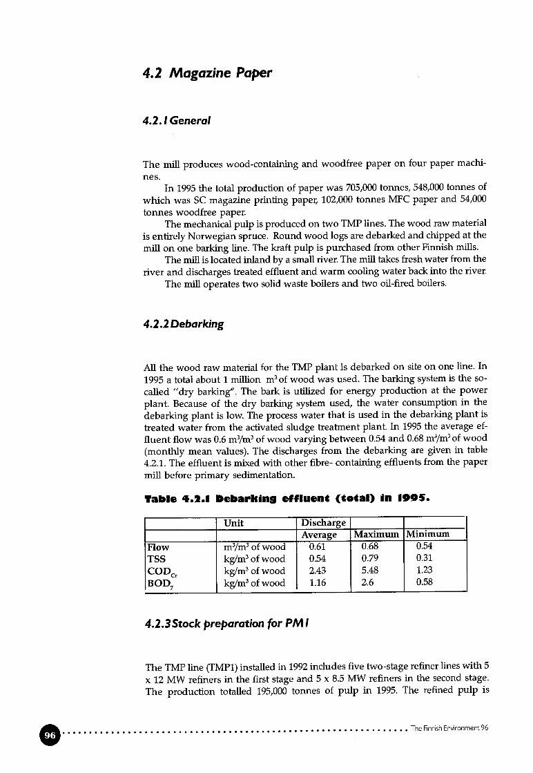
4.2 Magazine Paper
4.2.! General
The miii produces wood-containing and woodfree paper on four paper machi
nes.In 1995 the total production of paper was 705,000 tonnes, 548,000 tonnes of
which was SC magazine printing paper, 102,000 tonnes MFC paper and 54,000tonnes woodfree paper.
The mechanical pulp is produced on two TMP lines. The wood raw material
is entirely Norwegian spruce. Round wood logs are debarked and chipped at themiii on one barking line. The kraft pulp is purchased from other Finnish milis.
The miil is located inland by a small river. The miii takes fresh water from theriver and discharges treated effluent and warm cooling water back into the river.
The miii operates two solid waste boilers and two oil-fired boilers.
4.2.2 Debarking
Ali the wood raw material for the TMP plant is debarked on site on one line. In
1995 a total about 1 million m3 of wood was used. The barking system is the so
called “dry barking”. The bark is utilized for energy production at the power
plant. Because of the dry barking system used, the water consumption in the
debarking plant is low. The process water that is used in the debarking plant is
treated water from the activated sludge treatment plant. In 1995 the average ef
fluent flow was 0.6 m3/m3of wood varying between 0.54 and 0.68 m3/m3of wood
(monthly mean values). The discharges from the debarking are given in table
4.2.1. The effluent is mixed with other fibre- containing effluents from the paper
miil before primary sedimentation.
Table 4.2.1 Debarking effIuen (total) in 1905.
Unit DischargeAverage Maximum Minimum
Flow m3/m3of wood 0.61 0.68 0.54TSS kg/m3of wood 0.54 0.79 0.31
CODC kg/m3 of wood 2.43 5.48 1.23
BOD7 kg/m3of wood 1.16 2.6 0.58
4.2.3Stock preparation for PM 1
The TMP line (TMP1) installed in 1992 includes five two-stage refiner lines with 5
x 12 MW refiners in the first stage and 5 x 8.5 MW refiners in the second stage.
The production totalled 195,000 tonnes of pulp in 1995. The refined pulp is
Q The Finnish Environment 96

screened and cleaned before it is stored at a consistency of about 4% in two storage towers. Screening and cleaning rejects are refined in four reject refiners (8.5MW each). The puip is bleached with dithionite.
The energy consumption in TMP1 is 3.1-3.6 MWh/tonne of pulp, over 40%of which is recovered as steam. The heat energy is reused for heating on the TMPline and in the paper production.
The process water used in TMP1 (7-8 m3/t of pulp) is entirely ffltered whitewater from the paper machine. The process water is discharged from pulpwashing into the effluent treatment plant.
The purchased kraft pulp is slushed and diluted in the white water from thepaper machine and refined before being mixed with the other paper furnish components.
The ffflers come to the mifi with a 90% dry-solids content and are diluted toa 50% consistency before use.
4.2.4Paper machine (PM 1)
PM1 produces SC magazine printing paper. The furnish is TMP (50-60%),bleached kraft pulp (10-25%) and talc and clay fillers (35-45%). In 1995 the production was 326,000 tonnes of paper. PM1 was installed in 1992.
PM1 does not have a size press. The paper is finished by off-machine supercalenders. The paper is then re-reeled and wrapped.
Talc and kaolin are used as fillers. Other chemicals like retention chemicals,slimicides, dyes etc. are also used at PM1.
PM1 consumes about 11 m3 of chemically treated fresh water/tonne of paper.The water is mainly used in the wet end showers and some is used for dilutingthe wet end chemicals. Filtered fresh water is used for cooling purposes. Theconsumption of cooling and sealing water is a minimum of about 11 m3/t of paperin the winter time (monthly mean value) and a maximum of about 19 m3It ofpaper in the summer time. In the winter time part of the cooling water can bereused as raw water for the manufacturing of chemically purified process water.In the summer time ail the cooling water is discharged into the receiving waterthrough the clean water sewer.
A white water filter produces a clear ifitrate that is used in the TMP plant.
4.2.5 Energy production
The heat energy is produced for the whole paper mii in two boilers using biofuel(fluidized bed: 80 MW and 67 MW) and two oil-fired boilers (62 MW and 28 MW).About 90% of the heat energy is produced in the two fluidized bed boilers andabout one-third is produced with biofueis (table 4.2.2).
In 1995 the electrical energy production was 105 GWh in the mffl’s ownpower plant and 9 GWh were produced by water power. The rest (1,612 GWh)was purchased. A heat excess of 49 GWh was sold outside the miil for districtheating.
The Finnish Environment 96

Tabio 4.2.2 Fueis used at the power plant.
Fuel Heat energy production
(%))iI 13.9iludge 4.53ark 23.5‘eat 53.8hips and wood waste 4.4
[‘otal 100
4.2.6External treatment. Discharges and emissions into water andthe air, solid waste
Waste water is discharged at several points of the process. The main dischargesare a clear filtrate from TMP1 and PM1 and rejects from TMP1 and PM1 (table4.2.3)
Table 4.2.3 Effluent discharges from TMPI and P1119odng for effluent treatment.
Discharge Effluent flow TSS CODCr B007(m3/t of paper) (kg/t) (kg/t) (kg/t)
Clear fiitrate 4.7 0.26 5.9 2.4Reject from PM1 1.9 28.0 2.1 1.0Miscellaneous 4.1 9.5 5.0 2.4Total 10.7 37.8 13.0 5.8Analytical methods see table 4.2.7.
The effluents are treated m an activated sludge treatment plant (AS) with fiotafion as the post- treatment. The activated sludge treatment plant was installed in1990. Fibre-containing effluents are led to sedimentation, where 95-96% of thesuspended solids are separated from the effluent and led to the sludge handling.The primary treated effluent is mixed with fibre-free effluents and treated in the
activated sludge treatment plant. The reduction rates in the AS plant are shownin table 4.2.4.
Table 4.2.4 Reduction rates in the activated sludgetreatment plant in 1995.Average and variation of monthly mean value.
Reduction (%)Average Variation
BOD7 99 98.3-99.4
COD 91 88.5-93.9Tot-P 74 15-90Tot-N 46 0-75
The secondary sedimentation is divided into two lines. Occasional interruptions
in the effluent treatinent are taken care of by using tertiary treatment before
discharge.
Q The Finnish Envwonment 96
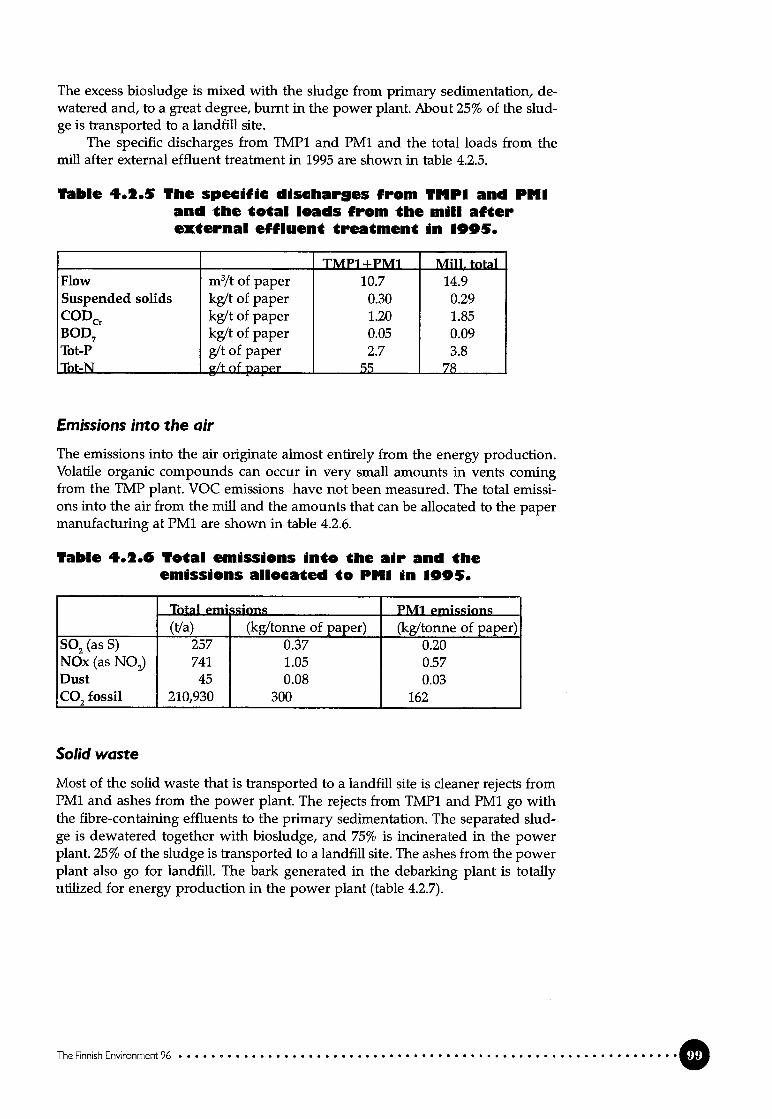
The excess biosludge is mixed with the sludge from primary sedimentation, dewatered and, to a great degree, burnt in the power plant. About 25% of the sludge is transported to a landfill site.
The specific discharges from TMP1 and PM1 and the total loads from themifi after external effluent treatment in 1995 are shown in table 4.2.5.
Table 4.2.5 The specific discharges from TMPI and PItIand the total Ioads from the miii afterexternal effluent treatment in 1905.
____________
TMPI +PM1 Miii. totalFlow m3/t of paper 10.7 14.9Suspended solids kg/t of paper 0.30 0.29CODcr kg/t of paper 1.20 1.85BOD7 kg/t of paper 0.05 0.09Tot-P g/t of paper 2.7 3.8Tot-N g/t of paper 55 78
Emissions into the air
The emissions into the air originate almost entirely from the energy production.Volatile organic compounds can occur in very small amounts in vents comingfrom the TMP plant. VOC emissions have not been measured. The total emissions into the air from the mifi and the amounts that can be allocated to the papermanufacturing at PM1 are shown in table 4.2.6.
Table 4.2.0 Total emissions into the air and theemissions ailocated te PItI in 1005.
Total emsions PM1 emissions(t/a) (kg/tonne of paper) (kg/tonne of paper)
S02 (as S) 257 0.37 0.20NOx (as NO2) 741 1.05 0.57Dust 45 0.08 0.03C02 fossil 210,930 300 162
Solid waste
Most of the solid waste that is transported to a landifil site is cleaner rejects fromPM1 and ashes from the power plant. The rejects from TMP1 and PM1 go withthe fibre-containing effluents to the primary sedimentation. The separated sludge is dewatered together with biosludge, and 75% is incinerated in the powerplant. 25% of the sludge is transported to a landfffl site. The ashes from the powerplant also go for landfill. The bark generated m the debarking plant is totallyutilized for energy production in the power plant (table 4.2.7).
The Finnish Environment 96 1 1

Table 4.1.1 SIud8e to incineration and solid waste forIandfiii (as diy matter).
Total miii TMP1 and PM1(t/a) (Va) (kg/tonne of paper)
incinerated landfffl incinerated landfill incinerated landfill
Sludge 25,028 8,252 9,532 3,143 29.2 9.6Ash 17,100 7,795 23.9Total 33.5
4.2. 7Monitoring of discharges
The monitoring of discharges into the receiving water is based on the Water Actand the consent given by the Water Court in August 1993. The analysis listed mtable 4.2.8 is stipulated in the monitoring programme.
Table 4.1.8 AnaIyss used in monitoring ddschargesinto water.
Anaiysis Analyticai methodpHConductivityTSS SFS 3037
COD SFS 5504BOD7 SFS 3019Tot-P SFS 3026 and KCL 228:8Tot-N SFS 5505
Besides the analysis listed above, dissolved phosphorus,P04-phosphorus, dis
solved nitrogen andN03-nitrogen are also analyzed.The monitoring of emissions into the air is based on the Air Pollution Cont
rol Act and the provisions given in the decision made by the Regional Environment Centre. Emissions of dust, NO and S02 are measured according to the standard methods listed in Appendix 1 and reported as mg/MJ.
4.3 Bleached kraft market pulp
4.3.1 General
The mifi is a non-integrated kraft pulp miii producing bleached ECF and TCF
pulp.In 1995 the total production of bleached pulp was 478,830 tonnes, one-third
of which was softwood pulp and the rest hardwood (birch) pulp. Most of the
pulp was ECF-.bleached. 2% of the production was TCF-bleached hardwood pulp.
The kraft pulp miil has two fibre lines and one chemical recovery line. The
pulp mifi, which has been producing pulp since 1967, was completely moderni
zed in 1992. The old fibre line was modernized and supplemented with oxygen
delignification. The other fibre line and the chemical recovery were newly built.
The Finnish Enronment 96

A new external treatment plant was started up half a year before the restart of thepulp miii.
One important principle of the company’s environmental policy is the implementation of the most advanced technology. Dry debarking, extended cooking,efficient washing, oxygen delignification and modern bleaching with the possible use of TCF were essential components m the choice of the technology for themodernized mifi.
The old pulp mill’s recovery boiler was reconstructed into a fluidized bedboiler for the burning of wood waste, bark and waste water treatment sludge.
4.3.2 Debarking
Round wood logs are debarked on two debarking lines, one for pine and one forbirch. Dry debarking is used on both lines. Some steam is used in the thawingconveyor only in the winter. After the barking drums, the Iogs are washed. Thebark is pressed and burnt in the bark boiler.
The water consumption in the debarking is 10 l/s per barking line (0.3 m3 ofwater/m3of wood). The waste water from the debarking plant is Ied to the wastewater treatment plant. Measured data about the pollution load from the debarking plant is not obtainable separately. Only the total effluent going to the wastewater treatment is regularly analyzed.
In 1995 the total wood consumption was about 2.4 million m3 (65% hardwood, 35% softwood), about 385,000 m3 of which was sawmffl chips. The specificwood consumption was 6 m3 unbarked wood/ADt of softwood pulp and 4.5 m3/ADt of hardwood pulp.
4.3.3 Process description
The pulp miil includes two fibre lines (figure 4.3.1). The oider fibre line with acapacity of 600 ADI/d is mainly used for the production of softwood pulp. Theother fibre line is mainly used for the production of hardwood pulp with a capacity of 1,100 ADt/d. The joint batch cooking plant includes 10 batch digesters.Oxygen deligriification is done in one stage on both fibre lines. The delignification of softwood pulp is extended to a Kappa of 20-22 in cooking, and after oxygen delignification the Kappa is 14-16. The Kappa leveis for hardwood pulp are17-19 and 12-13 respectively. After oxygen delignification the pulp is washed intwo wash presses.
The pulp miil produces ECF and TCF bleached softwood and hardwoodpulp on both fibre lines. ECF bleaching is performed in four (softwood) or five(hardwood) stages with oxygen- and hydrogen peroxide-reinforced alkali stages.In TCF bleachirtg the pulp is bleached solely with hydrogen peroxide. A chelating agent is used in TCF bleaching to avoid decomposition of the hydrogen peroxide.
After bleaching the pulp is dried, cut and packed into bales for transportailon.
The Finnish Environment 96

soooo
Figure 4.3.1 Block diagram of the bleached kraft pulp miii
The weak liquor from pulp washing is evaporated in a 6-effect evaporation pknt
(capacity: 600 t H20/h) and concentrated to a 72% dry-solids content and then
burnt in the recovery boiler (capacity: 2,800 t DS/d).The smelt ftom the recovery boiler is dissolved and pumped into the causti
cizing plant to regenerate the white liquor (6,000 m3 white liquor/d). The lime
mud is burnt in the ilme kiln (450 t CaO/d).Strong malodorous gases are collected from the cooking plant and the eva
poration plant and burnt in a separate burner. If the gas burner is out of operati
on, the strong malodorous gases are burnt in the lime kun.Weak malodorous gases from the cooking plant are burnt in the recovery
boiler as tertiary ak Weak malodorous gases from the evaporation plant are burnt
as combustion air in the gas burner for strong malodorous gases; weak malodo
rous gases from causticizing are burnt as combustion air in the lime kun.Because of the very low sulphur emissions, which are the resuit of the effi
cient internal and external recovery of the sulphur, the sulphidity in the white
Iiquor tends to rise to a high level (above 40). There is also an excess of sodium in
the chemical recovery system. The sulphur and sodium content in the system are
balanced by taking out white liquor from the system. The white Iiquor is sold to
other milis. Another way of taking out the sulphur and sodium from the system is
to eject into the sewer flue gas scrubbing washing liquor that contains Na2SO4
and waste acid from the tail oil plant.Non-process compounds are taken out of the process chemical circulation
with dregs and lime mud from the causticizing plant. The dregs and ilme mud
are transported to a landfffl with a 45-50% dry-solids content. A large amount of
phosphorus is also taken out of the system in this way. The phosphorus content
in the waste water from the process is low (see table 4.3.1), due to extended delig
nification before bleaching and because a relatively small alkali demand for the
neutralisation of the acid bleaching effluent makes it possible to use chemicals
The Finnish Environment 96
SOFTW000750.000
1.450.000w000

(e.g. CaO) other than ilme mud in the neutralization. The phosphorus content inthe waste water is further reduced in the external treatment plant before it isdischarged into the recipient.
4.3.4Energy production and consumption
The pulp mifi consumed 700 kWh/ADt of electricai energy and 13 GJ/ADt of heatenergy (in 1995).
Heat energy is produced in the recovery boiler and the barkboiler. The electrical energy is produced in a turbine with back-pressure steam. In 1995 the totalproduction of electrical energy was 631 GWh and the total production of heatenergy was 2,115 GWh in the recovery boiler and 627 GWh in the bark boiler(including the steam energy used for electrical energy production). No excessheat energy is sold, but excess eiectrical power is sold to the national net (about600 kWh/ADt in 1995).
About 30% of the fossil fuel used in the ilme kiln is repiaced by tail oil andmethanol from the condensate handling. Soap is also partly burnt in the recoverybofier. AH the tail oil and soap is burnt on site.
4.3..5External treatment. Discharges and emissions into water andthe air, solid waste
Discharges into water
The main discharge from the process into water is the bieaching waste water. Alithe waste water is biologically treated before bemg discharged into the recipient.The polluting load coming from the pulp miil for external treatment is shown intable 4.3.1.
Table 4.3.1 Total dischar9e from the process oing tothe external waste water treatment in1905.
Process discharge(t/d) (kg/ADt)
COD 76.2 58BOD7 28.5 22Tot-P 0.059 0.045Tot-N 0.191 0.145AOX 0.88 0.67
The acid waste water from bleaching is neutralized before being mixed with other waste water. After pre-screening the waste water is pumped to the primaryclarffler. Clarified waste water flows to an equalization basin equipped with mixers.
The biological treatment takes place in an extended aeration (iow organicloading) activated sludge treatment plant (retention time about 1 day). Beforeactivated sludge treatment the pH and the nutrient content (phosphorus andnitrogen) of the waste water are adjusted and the water is cooled below 40° C.After biological treatment the waste water flows through an ecological pond be
0The Finnish Environment 96

fore it is discharged into the receiving water. The ecological pond is an aerated
pond into which fish and plants have been intioduced. The retention time is 3-5
days.The reduction rates of pollutants in the waste water treatment plant is shown
in table 4.3.2.If there is a larger accidental spill at the pulp miii that would cause damage
to the biological treatment, the waste water is directed to the spffl pond, where it
is stored until it can be pumped to the activated sludge treatment at a flow rate
which does not affect the biological activity.Primary sludge and biosludge are thickened and then dewatered in a beit
press to a 20% dry-solids content. The sludge is mixed with bark and burnt in thebark boiler.
Table 4.3.2 Reductdon rates in the waste watertreatment plant (1995)(mean value of monthly average).
Primary Activated sludge Ecological pond Totalsedimentation treatment
(%) (%) (%) 21CODC 23 71 6 79BOD7 39 98 0 99Tot-P 13 88 7 90Tot-N - 47 22 40AOX 37 65 4 79
The specific discharges into the receiving water in 1994 and 1995 are shown in
table 4.3.3.
Table 4.3.3 Specific dischares into water in 1994and 1995(mean value of monthly average).
________
199 1994Flow m3/ADt 43 49TSS kg/ADt 0.2 0.3
CODcr kg/ADt 13 14BOD7 kg/ADt 0.2 0.3Phosphorus gfADt 5 6Nitrogen g/ADt 87 130AOX kg/ADt 0.14 0.14
The installed power of the treatment plant is 2 MWThe annual operating costs are FIM6 million.
Cooling water and other clean water are discharged separately (about 150
m3/ADt).
The Finnish Enironment 96

Emissions into the air
Four parallel three-field electrostatic precipitators separate the fly ash from theflue gases of the recovery boiler. The reduction rate of the dust is >99%. The flyash is returned to the black liquor. The flue gases from the recovery boiler arefurther treated in a scrubber to absorb the S02. If the pH of the washing liquor iswell above neutral, the reduction in S02 wffl he about 90%.
The flue gases from the lime kiln are treated in an elecftostatic precipitator (2parallel 2-field). The bark boiler is also equipped with an electrostatic precipitator.
The malodorous gas burner is equipped with a scrubber to reduce the S02and TRS.
The vents from the smelt dissolver are treated in an alkali scrubber beforethey are led to the recovery boiler scrubber. The vents from the tail oil plant aretreated in a separate scrubber.
Vents from the bleaching that contains some chlorine chemicals in gas formare treated by alkaline scrubbing.
The emissions into the air in 1995 are shown in table 4.3.4.
Table 4.3.4 Total and specific emissions into the airin 1905.
Dust NOx S02 TRS CI(as NO2) (as S) (as S)
Recovery boiler (tla) 68 667 5 3Lime kun (tja) 3 50 15 1TRS-gas burner (tla) 45 23Barkboiler (t/a) 24 134 10OthQr sources (tla) 17 0.1 64 192Total (t/a) 112 896 53 68 192Spec. discharge (kg/ADt) 0.24 1.91 0.11 0.14 0.4
Solid waste
The solid waste disposed of at landfffl sites is mainly ashes from the boilers, causticizing dregs, wood and bark waste and rejects (table 4.3.5.). In 1995 the amountof hazardous waste was 57 t (oils, solvents, paints, glue etc.).
Over 95% of the bark and wood waste from woodhandling ( 135,000 t DS in1995) is burnt in the bark boiler together with primary and biosludge from thewaste water treatment (5,740 t DS).
Table 4.3.5 The main types of soldd waste for Iandfiiiin 1905.
Solid waste(tonnes of 100% DS) (kg DS/ADt)
Ashes 8,704 18.2Dregs 4,662 9.7Bark, wood waste etc. 4,420 9.2Rejects 413 0.9
The Rnnish Enronment 96
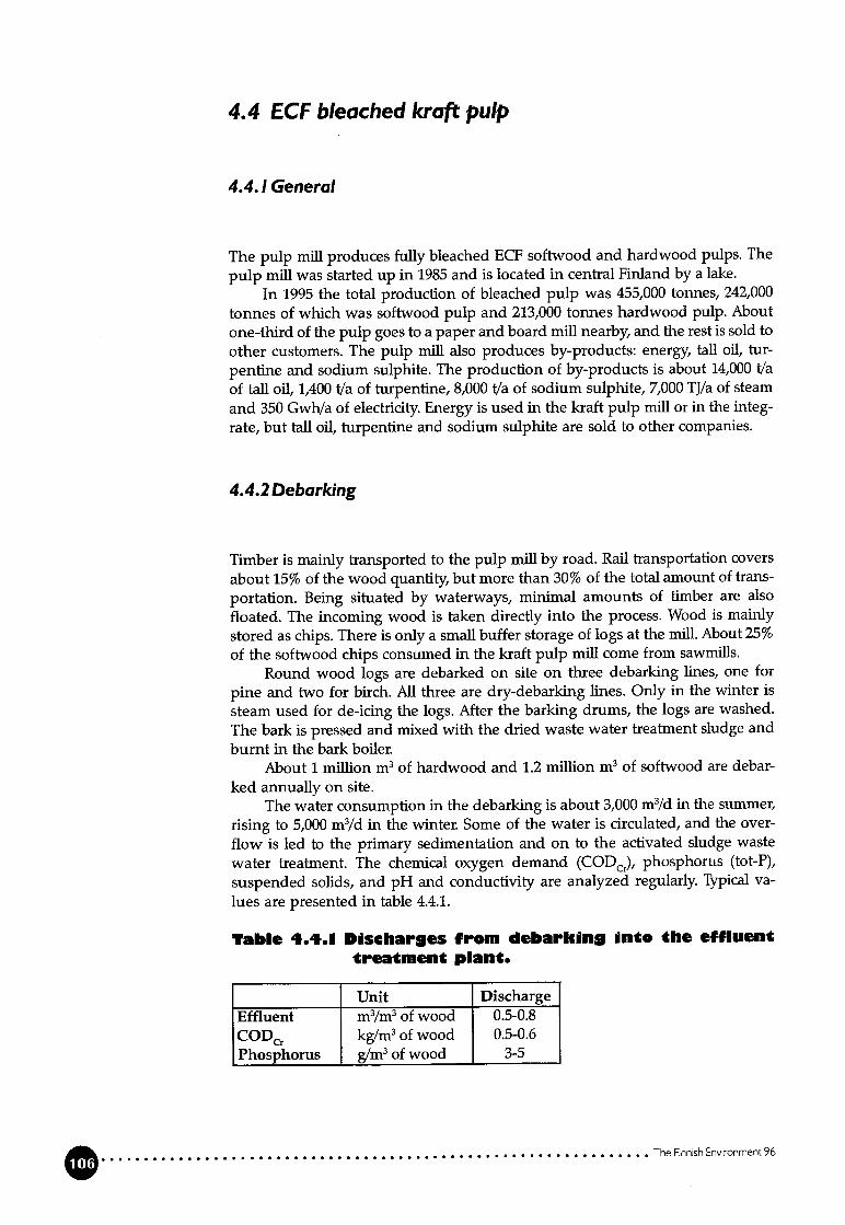
4.4 ECF bleached kraft pulp
4.4.! General
The pulp miii produces fully bleached ECF softwood and hardwood pulps. The
pulp miii was started up in 1985 and is located in central Finland by a lake.In 1995 the total production of bleached pulp was 455,000 tonnes, 242,000
tonnes of wKich was softwood pulp and 213,000 tonnes hardwood pulp. Aboutone-third of the puip goes to a paper and board mifi nearby, and the rest is sold toother customers. The pulp miii also produces by-products: energy, tail oil, turpentine and sodium sulphite. The production of by-products is about 14,000 t/aof tail oil, 1,400 Va of turpentine, 8,000 t/a of sodium sulphite, 7,000 TJ/a of steamand 350 GwhJa of electricity. Energy is used in the kraft pulp miii or in the integrate, but tail oil, turpentine and sodium sulphite are sold to other companies.
4.4.2 Debarking
Timber is mainly transported to the pulp miii by road. Rail transportation covers
about 15% of the wood quantity but more than 30% of the total amount of frans
portation. Being situated by waterways, minimal amounts of timber are also
floated. The incoming wood is taken directly into the process. Wood is mainly
stored as chips. There is only a small buffer storage of logs at the miil. About 25%of the softwood chips consumed in the kraft pulp mifi come from sawmffls.
Round wood logs are debarked on site on three debarking lines, one for
pine and two for birch. Ali three are dry-debarking lines. Only in the winter issteam used for de-icing the logs. After the barking drums, the logs are washed.
The bark is pressed and mixed with the dried waste water treatment sludge andburnt in the bark boiler.
About 1 miifion m3 of hardwood and 1.2 million m3 of softwood are debar
ked annually on site.The water consumption in the debarking is about 3,000 m3/d in the summer,
rising to 5,000 m3/cI in the winter. Some of the water is circulated, and the over
flow is led to the primary sedimentation and on to the activated sludge waste
water treatment. The chemical oxygen demand (COD), phosphorus (tot-P),
suspended solids, and pH and conductivity are analyzed regularly. Typical va
lues are presented in table 4.4.1.
Table 4.4.1 Diseharges from debarking into the effluenttreatment plant.
Unit Discharge
Effluent m3/m3of wood 0.5-0.8
COD kg/m3 of wood 0.5-0.6Phosphorus g/m3 of wood 3-5
0 The Finnish Environment 96

Ail the wood coming to the mifi either in chip or log form is weighed at the miii todetermine the quantity. Quality inspection covers identification of the wood spedes, size, moisture content and the degree of possible fungal detoriation. For sawmiil chips particle size distribution is ari essential part of the quality control.
4.4.3Kraft puip miii
Fibre lineThe pulp miii is a single line miii. There is one fibre line and one chemical recovery line (figure 4.4.1). The pulp miil produces ECF bieached softwood (pme) andhardwood (birch and aspen) pulp. Softwood and hardwood pulp is producedalternately at intervais of a few days.
Figure 4.4.! The kraft pulp miii
Production ofpulping chemccIs
The cooking method is the so-called extended continuous cooking, which makesit possible to cook to a lower lignin content than with conventional processes.Consequently, the puip needs less bleaching and the effluent load is substantiallyreduced. The chips are cooked in a Kamyr continuous digester with pre-impregnation to a Kappa of 25-27 for softwood pulp and 15-17 for birch and aspen pulp.The wood consumption is about 6 m3/ADt for softwood and 4.5m3/ADt for hardwood.
After Hi-Heat and two-stage diffuser washing the pulp goes through knotscreening to the screening plant. Knots are returned to the cooking. The screenedpulp is washed further on a two-stage washing ifiter.
After the washing and screening, the pulp is delignified in an oxygen stageto a Kappa of 15-17 for softwood pulp and 12-13 for hardwood pulp. The pulp iswashed before the five-stage bleaching in a press washer using evaporation condensate as the wash liquid. The process water flow is led counter-current fromthe washing stage after oxygen delignification to the beginning of the washing,where the liquor is separated and led to evaporation in the chemical recoverysystem.
The Rnnish Environment 96
Wood 1 Pulpinghondling 1 IWashing
IScreeningOxygen Stcige
Water stotion
1 Production of I1 blecching
chemicals
Bleaching 1 Drying Storoge
____________
BaIing 1 1 LoodingPulping
Activotedsludge plont
Sodium
__________
suIpiite
Recovery Plont— evoporotion— recovery boiler— energy
productionjToII ei)

During the bleaching, lignin and other impurities remaining in the pulp are removed. The bleaching chemicals used are oxygen, hydrogen peroxide and chlorine dioxide. Sodium hydroxide is used in the extraction stages. Chlorine dioxideis generated from sodium chlorate on site by the R3H process. The bleacbingsequence is: - E0 - - E() - D2.
Both softwood and hardwood pulps are always avaflable due to the integration with the paper and board mifi. The pulp that is sold outside the integrate isdried to a 90% dryness, cut and baled before shipping.
The total specific water consumption is 75 m3/ADt of bleached pulp and thespecific process effluent flow is 28 m3/ADt.
Recovery processThe weak black liquor from cooking is concentrated to a 75-80% dry-solids content by evaporation. The black liquor is thermaily cracked to a lower viscosityafter the first evaporation stage. Simultaneously volaffle sulphur compounds areremoved. This black liquor heat treatinent (LHT) results in lower sulphur dioxideemissions from the recovery boiler.
The concentrated black liquor is mixed with soda ash from the electrostaticprecipitators and burnt in the recovery boiler. The organic material burns intocarbon dioxide, while the inorganics are obtained as a smelt, which is dissolved inweak liquor from the causticizing plant to form green liquor. The high-pressuresteam generated m the recovery boiler is used in a 52 MW back-pressure turbogenerator, after which the low pressure steam is used as a source of heat whereneeded in the mifi.
Before causticizing, the green liquor is clarified and variations in the concentration are leveiled m a buffer tank. The green liquor is converted (causticized) into white liquor by the addition of ilme. The white liquor formed is thenfiltered and stored for reuse as cooking liquor.
The ilme mud is washed using secondary condensate from the evaporation.The lime mud washing ifitrate is used for smelt dissolving. The washed lime mud,calcium carbonate, is burnt in the ilme kiln to form CaO. Oil is used as fuel in theilme kIIn. Concentrated malodorous gases are oxidized to S02 in the lime kiln.The sulphur in the flue gases is recovered in the scrubber as sodium bisulphite,which is used in the bleaching plant.
4.4.5 Energy production
Energy is produced in the recovery boiler, a bark boiler of the fluidized bed typeand two oil-fired boilers for both the pulp miii and the paper miii. A new auxiliary boiler is being instailed in 1996.
4.4.6 External treatment. Discharges and emissionsinto water and the air, solid waste
Discharges into waterThe process waste water from the kraft pulp miii is treated m an activated sludgeplant together with waste water from the debarking plant and the adjacent papermifi. The effluents containing suspended solids are clarified before the activatedsludge treatment. The nitrogen content and pH in the waste water are adjusted
0 The Rnnish Enronment 96

before aeration. Ali the waste water going to the aeration is equalized in a lagoonof 25,000 m3. Ari additional pond is available in case of an emergency. The excessbiosludge from the secondary clarifier and the primary sludge are mixed, dewatered and burnt with the bark in the bark boiler.
Specific discharges are presented in table 4.4.2. The effidency of the treatment is shown in table 4.4.3, where reduction rates are reported based on inletand outlet numbers.
About 1,000 m3/d, or 3% of the effluent flow, and about 10% of the CODCrload going to the activated sludge treatment plant come from the paper miii.
Cooling water is discharged into the recipient in a separate “clean water”sewer.
Table 4.4.2 Specific ddschar9es into the receivingwater January - June 1996.
Process TSS BOD7 CODCr Tot-P Tot-N AOXeffluent(m3/ADt) (kg/ADt) (kg/ADt) (kg/ADt) (g/ADI) (g/ADt (kg/ADt)
Kraft pulp miii 28 1.15 0.43 21 10 210 0.32
Table 4.4.3 Poliution ioad goin9 to waste watertreatment (mainly from the kraft pulpmiii) in 1995.
(Average and min, and max. of 12 monthly mean values) and reduction rates in thewaste water treatment plant. Production average: 1,300 ADt of pulp/d.
Waste water treatment TSS BOD7 CODCr Tot-P Tot-N AOX(t/d) (t/d) (tld) (kgld) (kg/d) (tld)
In-average 8.3 22 74 100 672 1.1- (min-max) (14-38) (65-92) (90-123) (480-900) (0.8-1.4)Out-average 3.7 1.3 34 39 238 0.6• (min-max) (0.7-2.8) (30-42) (15-50) (130-375) (0.4-0.7’Reduction rates (%)- prim. sedimentation 92-95 - - - - -
- activated siudge treattnent 60-70 95-97 60-65 80-85 60-65 *) 50-55*) md. addition of N before aeration
Emissions into the airThe emission points for emissions into the air and the freatment methods areshown iii figure 4.4.2. Table 4.4.4 shows the specific emissions from the kraft pulpmifi.
Table 4.4.4 The specdfic emissdons fr.m the kraft pulpmiii in 1995.
r-”rS02 (kg S/ADt) 0.25TRS (kg S/ADt) 0.08NOx (kg NOJADt) 1.3Dust (kg/ADt’) 0.9
Ti.:i:I. muu mUl
The Finnish Enronment 96

Concentrated malodorous gases are collected and burnt in the lime kiln. Weak
malodorous gases of no heating value are collected and treated in two scrubbers.
At the bleaching plant and the bleaching chemical plant the process ventilation
exhausts are scrubbed to remove the traces of chlorine dioxide residues before
they are emitted into the air.
Solid wasteBark and other wood residues as weil as the mixed sludge from waste water tre
atment are utilized for energy production in the bark boiler. A small amount of
wood ashes was utilized as forest conditioning in 1995.The most important types of solid waste from the kraft pulp process and
energy production are lime mud and green liquor dregs, biosludge and primary
sludge, rejects from wood handling and wood ashes (table 4.4.5). The amount of
hazardous waste that was transported to a plant for the handling of hazardous
waste was 59 t m 1995. The specific amount of total solid waste for landfill was 43
kg/ADt of bleached pulp.
Tabio 4.4.5 SoIid waste for Iandfill in 1995.
Solid waste(tonnes. as 100% DS)
Lime mud 4,392Green liquor dregs 3,678Bio- and primary sludge 3,931Reject (woodhandling) 944Wood ashes 1,794Other 4,754
Hazardous waste 59TOTAL 19,552
The Finnish Environment 96
Figure 4.4.2 Emissions into the air and treatment methods.

4.4. 7Water supply and treatment
The raw water used at the pulp miil is pumped from the lake nearby. Mechanically treated raw water is used as the process water. Make-up water for the recoveryboiler and bark boilers is treated separately. The mechanically treated water ischemically treated by aluminium precipitation. Most of the chemically treatedwater is used for the final washing of the bleached pulp in the drying machine.
4.4.8Monitoring of discharges
The discharges into the recipient are monitored according to a momtoring programme confirmed by the authorities. The suspended solids, COD and conductivity are analyzed daily and the BOD, tot-P and tot-N are analyzed twice a week.The sampies are collected over a 24-hour period. AOX is analyzed once a monthfrom a composite sample of 24-hour sampies. Ali the analyses are based on homogenized and unffltrated sampies in accordance with standard methods.
S02emissions from the lime kiln and the recovery boiler are monitored continuously as well as dust and NO emissions from the recovery boiler. Detailed,manual monitoring of sulphur emissions (md. “diffuse” emissions) is carried outonce a year.
4.5 Integrated bleached kraft pulp and woodfreepaper
4.5.1 General
The miil produces bleached kraft pulp and coated woodfree paper on one papermachine. A new paper machine is scheduled to start up in the spring of 1997.
In 1995 the production of ECF bleach pulp was 324,740 tonnes (capacity370,000 tonnes/a), 28% of which was hardwood (birch) pulp and 72% softwoodpulp. The kraft pulp mifi produces no TCF pulp. Today about 40% of the pulpproduction goes to the paper mifi and the rest is sold to other paper mifis. In 1995the paper production was 250,000 tonnes of coated paper.
The miil is located by the estuary of a river. The mifi takes fresh water fromthe river and discharges treated effluent and warm cooling water back into theriver.
Energy for the kraft pulp mii and the paper mii is produced in the recoveryboiler, in a common wood-waste boiler and the boiler for malodorous gases at thekraft pulp mii, and occasionally in an oil-fired boiler.
The waste water from the kraft pulp mii is treated in an activated sludgetreatment plant and the waste water from the paper mii is treated in a chemicalfiotation plant. Non-contaminated cooling and cleaning water is discharged intothe recipient in separate sewers.
The Finnish Environment 96
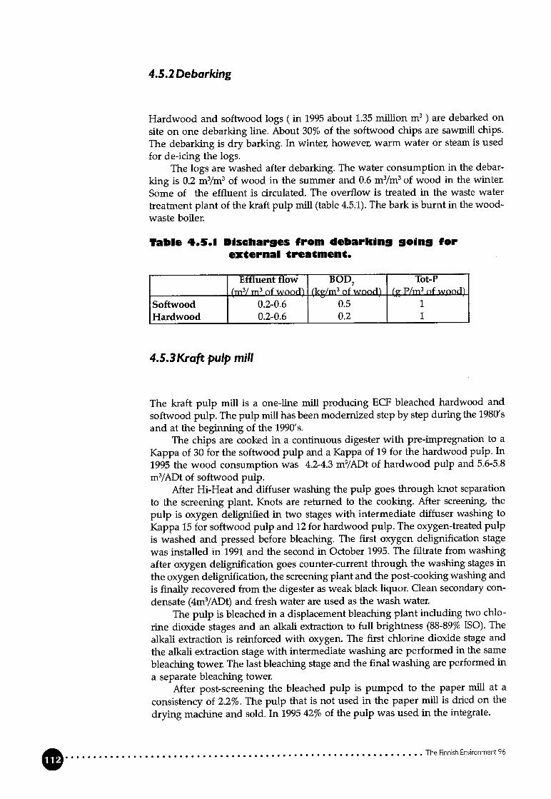
4.5.2 Debarking
Hardwood and softwood logs (in 1995 about 1.35 mullion m3) are debarked on
site on one debarking line. About 30% of the softwood chips are sawmull chips.
The debarking is dry barking. In winter, however, warm water or steam is used
for de-icing the logs.The logs are washed after debarking. The water consumption in the debar
king is 0.2 m3/m3 of wood in the summer and 0.6 m3/m3of wood in the winter.
Some of the effluent is circulated. The overflow ts treated in the waste water
treatment plant of the kraft pulp mifi (table 4.5.1). The bark is burnt in the woodwaste boiler.
Table 4.5.1 Discflares from debarkdng 9oin9 forextcrnal treatment.
Effluent flow BOD7 Tot-P(m3/m3 of wood) (kg/m3of wood) (g P/m3 of wood)
Softwood 0.2-0.6 0.5 1Hardwood 0.2-0.6 0.2 1
4.5.3Kraft puip miii
The kraft pulp miii is a one-line miii producing ECF bleached hardwood and
softwood pulp. The pulp miii has been modernized step by step during the 1980’s
and at the beginning of the 1990’s.The chips are cooked in a continuous digester with pre-impregnation to a
Kappa of 30 for the softwood pulp and a Kappa of 19 for the hardwood pulp. In
1995 the wood consumption was 4.2-4.3 m3/ADt of hardwood pulp and 5.6-5.8
m3/ADt of softwood pulp.After Hi-Heat and diffuser washing the pulp goes through knot separation
to the screening plant. Knots are returned to the cooking. After screening, the
pulp is oxygen delignified in two stages with intermediate diffuser washing to
Kappa 15 for softwood pulp and 12 for hardwood pulp. The oxygen-treated pulp
ts washed and pressed before bleaching. The first oxygen delignification stage
was installed in 1991 and the second in October 1995. The ifitrate from washing
after oxygen delignification goes counter-current through the washing stages in
the oxygen delignification, the screening plant and the post-cooking washing and
is finally recovered from the digester as weak black liquor. Clean secondary con
densate (4m3/ADt) and fresh water are used as the wash water.The pulp is bleached in a displacement bleaching plant including two chlo
rine dioxide stages and an alkali extraction to fuil brightness (88-89% ISO). The
atkali extraction is reinforced with oxygen. The first chlorine dioxide stage and
the alkali extraction stage with intermediate washtng are performed in the same
bleaching tower. The last bleaching stage and the final washing are performed in
a separate bleaching tower.After post-screening the bleached pulp ts pumped to the paper mifi at a
consistency of 2.2%. The pulp that ts not used in the paper miil is dried on the
drying machine and sold. In 1995 42% of the pulp was used in the integrate.
The Finnish Environment 96

Weak black liquor is concentrated in a multi-stage evaporation plant to a 67%dry-solids content and burnt in the recovery boiler (capacity 2,000 t DS/d). Thesmelt is dissolved in weak white liquor. The cooking chemicals are regenerated inthe causticizing and returned to the cooking. The ilme mud is washed with warmwater. The ilme for causticizing is regenerated in the Ilme kiln. The mud is predned with kun flue gases.
Foul condensates from evaporation and the cooking plant are treated in astripper for methanol separation. The methanol is burnt in a separate burner. Thetreated condensate, when contaminated, is discharged into the activated sludgetreatment plant.
In 1994-1995 the specific consumption of electrical energy was 650 kWh/ADtand heat energy 10 GJ/ADt in the kraft pulp mifi (including the activated sludgetreatment).
In 1994-1995 the specific process water consumption was 68 m3/ADt (including some cooilng water) and the cooling water consumption was 47m3/ADt.
4.5.4Paper miii
The paper mifi produces multi-coated fine paper on one paper machine with anoff-machine coater. The coated paper is super- or soft-calendered and deliveredto the dients either as sheets or as reels. The paper mii obtains electrical and heatenergy from the energy production on site, and the required additional electricalenergy is purchased from the national grid.
In 1995 the production was 250,000 tonnes of paper (nominal capacity 330,000tonnes of paper), consisting of 55% bleached kraft pulp and 45% coating pigments and fillers.
Softwood and hardwood pulp is pumped from the kraft pulp mifi at a 2.2%consistency. The chemical pulp is refined in the stock preparation plant.
The process water consumption is 17 m3/ADt of paper (13-23 m3/ADt of paper) and the consumption of cooilng water is 12m3/ADt of paper (11-21 m3/ADt ofpaper).
In 1994-1995 the specific electrical energy consumption (including coatingand and the coating kitchen, and cutting) was 920 kWh/t and the specific heatenergy consumption was 6.3 GJ/t. In addition, 4,000 tonnes of liquefied petro.leum gas (0.73 GJ/t) are used to generate hot air for drying at the coating machine.
4.5.5 Energy production
Energy for the pulp and paper mifi is produced in the recovery boiler, a boiler forburning malodorous gases, a wood-waste boiler and occasionally in an oil-firedboiler (table 4.5.2). The wood-waste boiler is a rebuilt old recovery boiler. Thewood-waste boiler will be replaced by a new fluidized bed boiler for wood wasteand peat in the spring of 1997. In 1994-1995 96% of the energy was producedfrom renewable fuel resources (table 4.5.3).
The Finneh Environment 96
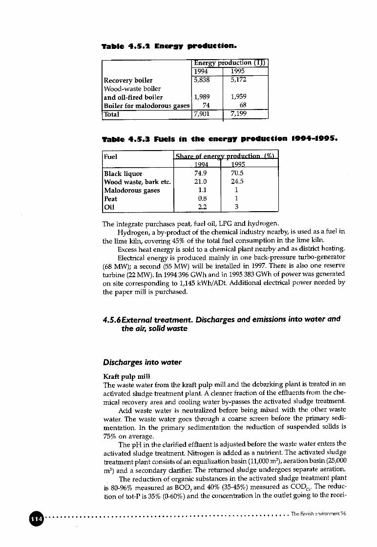
Table 4.5.2 Energy production.
Energy production (TJ)1994 1995
Recovery boiler 5,838 5,172
Wood-waste boilerand oil-fired boiler 1,989 1,959Boiler for malodorous gases 74 68Total 7,901 7,199
Table 4.5.3 Fueis in the energy production 1904-1995.
Fuel Share of enerv production ()1994 1995
Biack iiquor 74.9 70.5Wood waste, bark etc. 21.0 24.5Malodorous gases 1.1 1Peat 0.8 1Oil 2.2 3
The integrate purchases peat, fuel oil, LPG and hydrogen.Hydrogen, a by-product of the chemical industry nearby, is used as a fuel in
the ilme kiln, covering 45% of the total fuel consumption in the ilme kun.
Excess heat energy is sold to a chemical plant nearby and as district heating.
Electrical energy is produced mainly in one back-pressure turbo-generator
(68 MW); a second (55 MW) wffl be instailed in 1997. There is also one reserve
titrbine (22 MW). In 1994 396 GWh and in 1995 383 GWh of power was generated
on site corresponding to 1,145 kWhIADt. Additional elecfrical power needed by
the paper miii is purchased.
4.5.6External treatment. Discharges and emissions into water andthe air, solid waste
Discharges into water
Kraft pulp miiiThe waste water from the kraft pulp miii and the debarking plant is treated in an
activated sludge treatment plant. A cleaner fraction of the effluents from the che
mical recovery area and cooling water by-passes the activated sludge treatment.
Acid waste water is neutralized before being mixed with the other waste
water. The waste water goes through a coarse screen before the primary sedi
mentation. In the primary sedimentation the reduction of suspended solids is
75% on average.The pH in the clarified effluent is adjusted before the waste water enters the
activated sludge treatment. Nitrogen is added as a nutrient. The activated sludge
treatinent plant consists of an equalization basin (11,000 m3), aeration basin (25,000
m3) and a secondary clarifier. The returned sludge undergoes separate aeration.
The reduction of organic substances in the activated sludge freatment plant
is 80-96% measured as BOD7and 40% (35-45%) measured as CODCrO The reduc
ilon of tot-P is 35% (0-60%) and the concentration in the outlet going to the recei
The Finnish Environment 96

ving water is 1.0 mg tot-P!1 (0.6-1.6 mg/1). The mean tot-N reduction is about 30%,but the reduction varies over a wide range. The concentration in the outlet isabout 5 mg tot-N/1 (3.5-10 mg tot-N /1).
The excess biosludge is thickened and mixed with the primary sludge beforebeing dewatered in two parallel filter beit presses. The mixed sludge is burnt inthe wood-waste boiler.
The total discharges from the kraft pulp miii into the receiving water areshown in table 4.5.4.
Tabi. 4.5.4 Total specific dischar9es from tbe kraftpulp miii into the recipient in 1094-1995.
Flow TSS BOD7 CODCr Tot-P Tot-N AOX(m3/ADt) (kg/ADt) (kg/ADt) (kg/ADt) (g/ADt) (g/ADt) (kg/ADt)
Activated sludg 36.5 2.0 1.2 28 37 200 0.37Recovery area 30.5 0.1 0.9 3 3 70 -
Total 67.0 2.1 2.1 31 40 270 0.37
The energy consumption of the waste water treatment is 0.54 kWFVm3’includingpumping, aeration and sludge handling.
The annual operatirLg costs are about FIM 2 million, including energy, chemicals, operating and maintenance.
Occasional and accidental spffls are collected from the chemical recoveryarea and returned to the chemical recovery system. Smaller spffls are led to thewaste water treatment plant.
Paper miiiThe waste water from the paper muU, including the paper machine clear filtrate,rejects from stock preparation and broke handling, waste water from the coatingkitchen and size preparation, is treated with chemical precipitation. Fibre andsuspended solids containing waste water are pre-treated in a primary clarifierbefore being mixed with the clear ifitrate, pH acljustment chemicals and flocculating chemicals, and the sludge is separated by fiotation in two parallel tanks. Thechemical sludge is taken either directly to sludge handling or to the primary ciarifier and then together with the primary sludge to siudge handling. The mixedsludge is conditioned with a poiymer and then dewatered in a filter beit pressbefore it is transported to a iandfffl site. The ifitrate from the ifiter press is returned to the primary clarifier.
The discharges from the chemical treatment plant into the receiving waterin 1994-1995 are shown in table 4.5.5.
The reduction of suspended solids in the waste water treatment exceeds 99%.A typical reduction for BOD7 is 80-85%, for CODCr 90-95%, for phosphorus 90%and for nitrogen 70-80%.
Tabie 4.5.5 Specific dischar9es from the paper miiiafter chemical treatment 1994-1005.
DischargeFiow (m3/t of paper) 17TSS (kg/tofpaper) 0.8BOD7 (kg/t of paper) 1.3CODcr (kg/t of paper) 2.2Tot-P (g/t of paper) 2.8Tot-N (g/t of paper) 46
The Finnish Environment96

Emissions into the air
Kraft pulp miiiStrong malodorous gases are collected from the cooking plant (condenser, tur
penfine decanter) and the evaporation plant and burnt in a separate boiler. Theflue gases have a high concentration of S02.The sulphur is recovered in a washer
as sodium bisulphite. The treated flue gas goes further to the flue gas scrubber at
the recovery boiler. The amount of bisulphate generated is enough to replace theS02-water amount earlier used in the washing of the bleaching plant vents andfor acidification of the bleached pulp.
Weak malodorous gases are coilected from black liquor tanks in the evaporailon plant, soap tanks and washer in the tail oil plant, condensate tanks and tanksin the causticizing plant. The weak malodorous gases are burnt in the recoveryboiler mixed with tertiary combustion air.
The smelt dissolver is equipped with a separate scrubber. The vents are further treated m the recovery boiler scrubber.
The recovery boiler is equipped with an electrostatic precipitator (two parallel) and a scrubber. The treated flue gases from the boiler of malodorous gasesand the treated smelt dissolver vents are also treated in the same scrubber. Thegases are washed with sodium hydroxide, and in the second stage the rest of theheat in the flue gases is recovered as warm water.
The flue gases from the lime kun are treated in an electrostatic precipitator.The emissions of H2S and S02 from the recovery boiler and the ilme kiln are
monitored continuously.The wood-waste boiler is also equipped with an electrostatic precipitator.In 1994-1995 the total emission of sulphur into air from the kraft pulp pro
cess was 0.65 kg S/ADt (table 4.5.6) and from additional energy production 0.18kg S/ADt
Table 4.5.0 Emissions into the air.
S02 TRS Totai - S NOx Dust(kg S/ADt) (kg S/ADt) (kg S/ADt) (kg NO,/ADt) (kg /ADt)
Recovery boiler 0.13 0.02 0.15 0.88 0.72Lime kun - 0.01 0.01 0.27 0.02Other 0.19 0.30 0.49Process, total 0.32 0.33 0.65 1.15 0.74Energyproduction 0.18 - 0.18 0.75 0.01
Puip and paper,kotal 0.50 0.33 0.83 1.90 0.75
Paper miiiThe main polluting emissions into the air caused by the production of paper comeftom the production of the energy used at the paper mifi. These emissions are
discussed above under the heading “Kraft pulp miil” (see table 4.5.6).
Solid waste
The generation of solid waste in 1995 is shown m table 4.5.7. Bark and wood
waste are utilized for energy production in the wood-waste boiler (125,170 ton
nes, calculated as dry matter). Primary and biosludge from the activated sludge
freatment plant are also burnt in the waste-wood boiler (3,786 tonnes, calculated
as dry matter). The ashes from the waste-wood boiler are transported to a landfill
The Finnish Environment 96

site. The sludge from the paper mffl’s waste water treatment is landfilled. Theamount of waste from the cores used in the paper reels totalledl,068 t. This wasteis returned to Finnish milis that produce core board.
Table 4.5.1 SoIid waste going te a landfiii site from thepulp and paper miii in 1095 (as diy solid).
Soiid waste(t) (kg/ADt)
Kraft puip miiiDregs 2 760 8.5Rejects 150 0.5
Paper miiiWaste water siudge 18 500 74
Energy productionWood ashes 2 747Peatashes 203
4.6 Integrated bleached pulp and wood-containingpaper
4.6.1 General
The integrate produces bleached pulp and coated wood-containing paper. Thereis also a sawmill and a plywood mifi on the site. A new softwood kraft pulp lineand a modernized hardwood kraft pulp line and chemical recovery line wffl comeinto operation at the end of 1996. The situation in 1995 is primarily presentedhere. The modernization of the kraft pulp mifi is presented in brief in section4.6.7.
In 1995 the kraft pulp miii produced 455,000 tonnes of ECF bleach pulp, 55%of which was hardwood (birch) pulp and 45% softwood pulp. The kraft pulp mifiproduced 7,000 tonnes of TCF softwood pulp. About 30% of the kraft pulp production was used in the paper miil and the rest was sold to other paper milis. In1995 the paper production was 466,000 tonnes of coated wood- containing paper.
The miil is located iriland by a large lake. The miii takes raw water from thelake and discharges treated effluent and warm cooling water back into the lake.
Energy for the kraft pulp miii and the paper miii is produced in the recoveryboiler and the boiler for malodorous gases at the kraft pulp mifi, in two bark boilers and a natural gas-fired gas turbine with a waste heat boiler.
The waste water from the kraft pulp mifi and the paper mifi is treated in anactivated sludge treatment plant. Clean effluent and the cooling water are discharged into the recipient in a separate sewer.
The Finnish Environment 96

4.6.2 Debarking
There are two debarking plants, one for the kraft pulp mifi and one for themechanical pulp production.
Hardwood and softwood Iogs for the kraft pulp miii are debarked on separate debarking lines (in 1995 about 1.6 mihlion m3). The debarking is dry. In thewinter warm water is used for de-icrng the logs. The kraft pulp miil uses an additional 0.7 million m3 of chips and sawdust from the sawmffl and the plywood
plant.Wood (spruce) for the mechanical pulp production is debarked in a separate
debarking plant (about 0.4 million m3 of wood in 1995) using wet barking.The total waste water flow from the debarking plants is 1,700 m3/d (annual
average). The effluent from the two debarking plants is treated for the separation
of suspended solids in a sedimentation basin. The overflow is treated further inthe activated sludge treatment plant. The clarified effluent from the sedimentati
on is not monitored. The sedimentation sludge is dewatered and transported to a
landfili site or mixed with the bark, which is burnt in the bark boilers or frans
ported to a landfill site.
The Finnish Environment 96
Production Industriol wood PuIp to Paper424.000 m other miHs 466.000
329,000
Figure 4.6.! Fibre material balance

46.3Kraft pulp miII
The kraft pulp mifi has separate fibre liuies for hardwood and softwood. Sawdustand smafl-size chips are cooked in a separate continuous digester. This pulp ismixed with the hardwood pulp after cooking. Process chemicals and energy arerecovered on a joint recovery line. The mifi produces ECF bleached hardwoodand softwood pulp and TCF bleached softwood pulp. The pulp miii is being modernized (1995-96) and the modernization is planned for completion by the endof 1996. The modernization is discussed in section 4.6.7. The miii configurationand the data presented relate to the process situation in 1995.
Pulp cooking on the hardwood fibre line takes place in five batch digesters.The wood consumption is about 4.3 m3/ADt of pulp (3.2 m3/ADt debarked andchipped on site and 1.1 m3/ADt from the sawmffl and plywood mifi). The Kappaafter cooking is 19.
The pulp is washed ii two parallel four-stage DD-washers, screened andthickened before oxygen delignification in two stages to Kappa 14. The oxygendelignified pulp is washed in a two-stage DD-washer, and the washing filtrate isIed counter-current through the pulp washing to the chemical recovery system.The washed pulp is stored in a high-consistency tower and once again washedbefore bleaching.
On the softwood fibre line pulp cooking takes place in four batch digesters.The softwood consumption is about 5.8 m3/ADt of pulp (3.6 m3/ADt debarkedand chipped on site and 2.2m3!ADt sawmffl chips). The softwood pulp is cookedto Kappa 27-28.
The hardwood and softwood pulp is bleached with chlorine dioxide in separate five-stage bleaching plants with filter washing. The alkali extraction is reinforced with oxygen and peroxide. The pulp is finally treated with sulphur dioxide water or a bisulphite solution to remove residual chlorine dioxide. Hardwoodpulp is bleached to 89-90% ISO and softwood pulp to 86% ISO. The chlorinedioxide is produced on site using the ERCO R8 process.
Small amounts of TCF bleached pulp are also produced (7,000 ADt of softwood pulp in 1995). TCF pulp is produced on the hardwood fibre line. The pulpis oxygen-delignified to a lower Kappa level than normal. The pulp is then treated with an enzyme and a chelating agent (EDTA) before being bleached withoxygen and peroxide (bleaching sequence QX EOP P P P).
Ail the bleached hardwood pulp is dried and sold to other mifis in Finlandand abroad. Most of the bleached softwood pulp is pumped to the paper miii.The rest is dried and sold to other paper milis. In 1995 65% of the ECF softwoodpulp was used in the integrate.
The chemical recovery system was modernized in 1991 (7-stage evaporationplant, recovery boiler (capacity 2,700 t DS/d), turbo-generator and a system forcollecting and burning malodorous gases). The strong black liquor is evaporatedto a 75-76% dry-solids content before it is fed into the recovery boiler. The causticizing of cooking chemicals and regeneration of lime in the two Ilme kilns followthe conventional technique. Foul condensates from evaporation and the cookingplant are treated for the separation of methanoi and malodorous compounds.The methanol and weak malodorous gases from the recovery plant are burnt inthe burner for malodorous gases.
The net specific consumption of electrical energy is 770 kWh/ADt and heatenergy 13.2 GJ/ADt in the kraft pulp miii (annual average 1995).
The specific process water consumption was 73 m3!ADt and the consumption of sealing and cooling water was 72 m3/ADt.
The Finnish Environment 96

4.6.4Paper miii
The paper muU produces coated LWC paper on two lines. In 1995 the production
was 235,000 and 230,400 tonnes of paper respectively. The paper furnish is
approximately 35% mechanical pulp, 30% chemical pulp, the rest being coatingpigment, binders and additives. The electrical and heat energy consumed is
partially supplied by the energy production on site. Additional electrical energyis purchased. Softwood pulp ts pumped from the kraft pulp mifi and coatingagents are purchased.
The main process units are the groundwood mifi, the base paper macbines,coating kitchen, off-machine coaters, calendenng of coated paper, and cuttingand wrapping (figure 4.6.2).
The groundwood pulp is produced at a two-line groundwood plant. Theprocess steps at the groundwood plant are grinding, coarse and fine screening,centri-cleaning, thickening, post-refining, peroxide bleaching and pulp storage.The production capacity of the four grinders on line 1 is 260 tonnes of GW pulp/d and that of the two PGW grinders on line 2 is 170 tonnes of pulp/a. The totalannual production capacity is 150,000 t/a. In 1995 the production of mechariicalpulp was 142,600 tonnes. 78% of the mechanical pulp was peroxide bleached.
The production capacity of paper line 1 is 250,000 tonnes of paper/a (700 I/d)and the basis weight is 60-80 g/m2 (single coated) and 75-100 g/m2 (doublecoated). The production capacity of line 2 is 240,000 tonnes of paper/a (675 t/d) in
the grammage range of 35-70 g/m2 (smgle coated paper grades). In 1995 the total
production was 466,000 tonnes of paper.
Figure 4.6.2 Principal flow diagram of the paper miii.
The Finnish Environment 96
Wood
Groundwood Stock preparation andmiii paper machines
Main rnaterial flow
Effluent
Re—ree)ers Coaters Re—reelers Super— Winders Wrappingcalenders machine
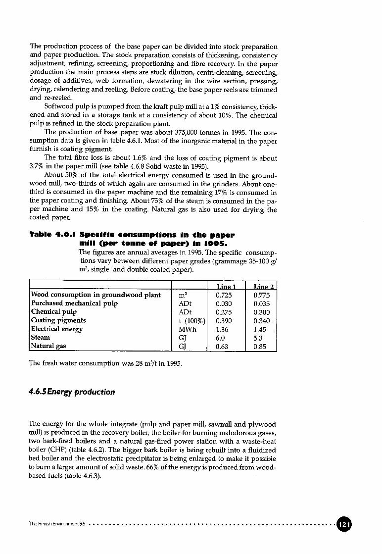
The production process of the base paper can be divided into stock preparationand paper production. The stock preparation consists of thickening, consistencyadjustment, refining, screening, proportioning and fibre recovery. In the paperproduction the main process steps are stock dilution, centri-cleaning, screening,dosage of additives, web formation, dewatering in the wire section, pressing,drying, calendering and reeling. Before coating, the base paper reels are trimmedand re-reeled.
Softwood pulp is pumped from the kraft pulp mii at a 1% consistency, thickened and stored in a storage tank at a consistency of about 10%. The chemicalpulp is refined in the stock preparation plant.
The production of base paper was about 375,000 tonnes in 1995. The consumption data is given in table 4.6.1. Most of the inorganic material in the paperfurnish is coating pigment.
The total fibre loss is about 1.6% and the loss of coating pigment is about3.7% in the paper miii (see table 4.6.8 Solid waste in 1995).
About 50% of the total electrical energy consumed is used in the groundwood miii, two-thirds of which again are consumed in the grinders. About onethird is consumed in the paper machine and the remaining 17% is consumed inthe paper coating and finishing. About 75% of the steam is consumed m the paper machine and 15% in the coating. Natural gas is also used for drying thecoated paper.
Table 4.0.1 Specific consumptions in the papermdli (per tonne of paper) in 1995.The figures are annual averages in 1995. The specific consumptions vary between different paper grades (grammage 35-100 g/m2, single and double coated paper).
_______
Line 1 Line 2Wood consumption in grotmdwood plant m3 0.725 0.775Purchased mechanical pulp ADt 0.030 0.035Chemical pulp ADt 0.275 0.300Coating pigments t (100%) 0.390 0.340Electrical energy MWh 1.36 1.45Steam GJ 6.0 5.3Natural gas GJ 0.63 0.85
The fresh water consumption was 28 m3/t in 1995.
4.6.5 Energy production
The energy for the whole integrate (pulp and paper mii, sawmffl and plywoodmiii) is produced m the recovery boiler, the boiler for burning malodorous gases,two bark-fired boilers and a natural gas-fired power station with a waste-heatboiler (CHP) (table 4.6.2). The bigger bark boiler is being rebuilt into a fluidizedbed boiler and the electrostatic precipitator is being enlarged to make it possibleto burn a larger amount of solid waste. 66% of the energy is produced from woodbased fueis (table 4.6.3).
The Finnish Envwonment 96
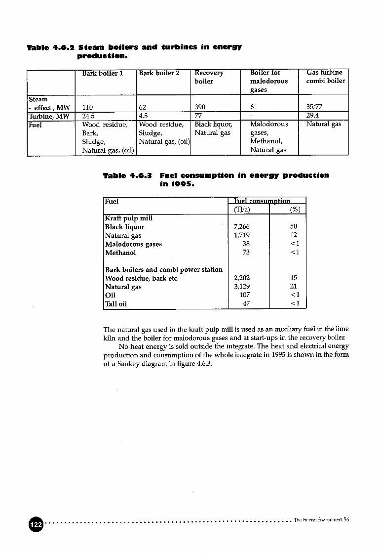
Table 4.0.1 Seam boilers and turbines in eneryproduction.
Bark boiler 1 Bark boiler 2 Recovery Boiler for Gas ttirbine
boiler malodorous combi boiler
gases
Steam
- effect,MW 110 62 390 6 35/77Turbine, MW 24.5 4.5 77 - 29.4
Fuel Wood residue, Wood residue, Black liquor, Malodorous Natural gas
Bark, Sludge, Natural gas gases,Sludge, Natural gas, (oil) Methanol,
Natural gas, (oil) Natural gas
Table 4.0.3 Fuel consumption in energy produetionin 1905.
Fuel Fuel consu iption
(TJ/a) (%)Kraft puip miii
Black liquor 7,266 50Natural gas 1,719 12
Malodorous gases 38 <1
Methanoi 73 <1
Bark boiiers and combi power station
Wood residue, bark etc. 2,202 15Natural gas 3,129 21Oii 107 <1
Tali oli 47 <1
The natural gas used in the kraft pulp mifi is used as an auxiliary fuel in the limekiln and the boiler for malodorous gases and at start-ups in the recovery boiler.
No heat energy is sold outside the integrate. The heat and electrical energyproduction and consumption of the whole integrate in 1995 is shown in the formof a Sankey diagram m figure 4.6.3.
The Finnish Environment 96

Natural gai4,848 TJ —34%
Figure 4.6.3 Heat and electrical energy balance for the integrate in 1995.
In 1995 the electrical power generation on site was 642 GWh, 385 Gwh of whichwas generated m the turbo-generator of the kraft pulp miii. Additionally, 455GWh of electrical power needed by the paper mifi was purchased (figure 4.6.3).
4.6.6 External treatment. Discharges and emissions into water andthe air, solid waste.
Discharges into water
Kraft puip miiiThe waste water from the kraft pulp miii and clarified waste water from the debarking plants are treated in the activated sludge treatment plant together withwaste water from the paper miil. Clean effluents (sealing and cooling water)from the kraft pulp miii, energy production and the paper mifi are dischargeddirectly into the recipient.
The waste water going for activated siudge treatment is neufralized beforeprimary sedimentation. The concentration of suspended solids after primary sedimentation is 35 mg/1 (annual average), giving an average reduction of 90%.The reduction of organic substances measured as BOD7and CODCr is not registered regularly.
After primary sedimentation, the waste water flows into an equalization pond.If there is an occasional discharge of waste water which differs in quality considerably from the normal situation, an emergency pond is available, from wherewater is pumped into the equalization pond. Nitrogen is added and the pH isadjusted before aeration in the activated sludge treatment. Normally, no phosphorus is added. The aeration pond in the activated sludge treatment plant is divided into three sections, in which the oxygen and sludge concentration can becontrolled separately. The retention time in the aeration is approximately 24 h. In
The Finnish Enronment 96
Paper miii 28%Puip miii 64%Saw miii 5%Piywood miii 1%Other, 2%
Oil 107 Ti —1%
Eiectricity1,098 CWh
Paper miii 60%Puip miii 33%Saw miii 3%Plywood miii 1%Ottieri 3%
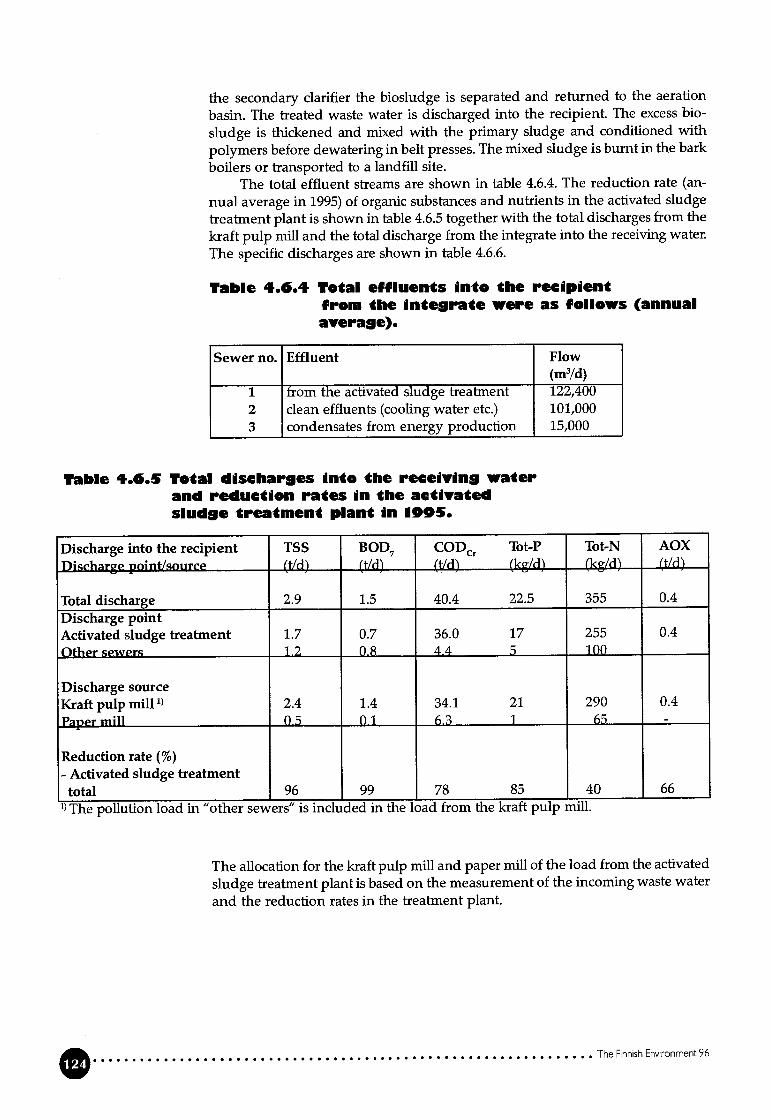
the secondary clarifier the biosludge is separated and returned to the aeration
basin. The treated waste water is discharged into the recipient. The excess bio
sludge is thickened and mixed with the primary sludge and conditioned with
polymers before dewatering in beit presses. The mixed sludge is burnt in the bark
boilers or transported to a landfill site.The total effluent streams are shown in table 4.6.4. The reduction rate (an
nual average in 1995) of organic substances and nutrients in the activated sludgetreatment plant is shown in table 4.6.5 together with the total discharges from the
kraft pulp miii and the total discharge from the integrate into the receiving water.
The specific discharges are shown in table 4.6.6.
Table 4.0.4 Total effluents into tbe recipdentfrom the dnterate were as follows (annualaverage).
Sewer no. Effluent Flow(m3/d)
1 ftom the activated sludge freatment 122,4002 ciean effluents (cooling water etc.) 101,0003 condensates from energy production 15,000
Table 4.0.5 Total discliarges into the receivin waterand reduction rates iii tbe activatedsIude treatment plant in 1995.
Discharge into the recipient TSS BOD7 CODC Tot-P Tot-N AOX
Discharge pointlsource (tld) (t/d) (t!d) (kg/d) (kg/d) (t/d)
Total discharge 2.9 1.5 40.4 22.5 355 0.4
Diseharge pointActivated sludge treatment 1.7 0.7 36.0 17 255 0.4
Othr sewers 12 0.8 4.4 5 100
Discharge sourceKraftpulp mi11’ 2.4 1.4 34.1 21 290 0.4
Papr miii ft5 0.1 6.3 1 65 -
Reduction rate (%)- Activated sludge treatmenttotal 96 99 78 85 40 66
The pollution load in “other sewers” is included in the load from the kraft pulp miil.
The allocation for the kraft pulp mifi and paper miil of the load from the activated
sludge treatment plant is based on the measurement of the incoming waste water
and the reduction rates in the treatnient plant.
The Finnish Enronrnent 96
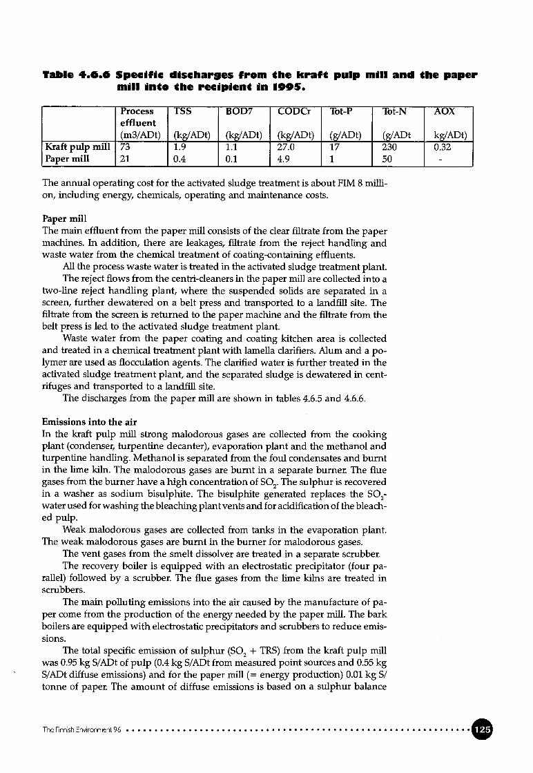
Tabi. 4.0.0 Specific dischares from the kraft puip miii and the papermiii into tbe recipient in 1095.
Process TSS BOD7 CODCr Tot-P Tot-N AOXeffluent(m3/ADt) (kg/ADt) (kg/ADt) (kg/ADt) (g/ADt) (g/ADt kg/ADt)
Kraft puip miii 73 1.9 1.1 27.0 17 230 0.32Paper miii 21 0.4 0.1 4.9 1 50 -
The annual operating cost for the activated sludge treatment is about FIM 8 million, including energy, chemicals, operating and maintenance costs.
Paper miiiThe main effluent from the paper mifi consists of the clear fflfrate from the papermachines. In addition, there are leakages, filtrate from the reject handling andwaste water from the chemical treatment of coating-containing effluents.
Ali the process waste water is tTeated in the activated sludge treatment plant.The reject flows from the centri-cleaners in the paper mifi are collected into a
two-line reject handling plant, where the suspended solids are separated m ascreen, further dewatered on a beit press and transported to a landfffl site. Theifitrate from the screen is returned to the paper machine and the ifitrate from thebeit press is led to the activated sludge treatanent plant.
Waste water from the paper coating and coating kitchen area is collectedand treated in a chemical treatment plant with lamella clarifiers. Alum and a p0-lymer are used as flocculation agents. The clarified water is further treated in theactivated sludge treatment plant, and the separated sludge is dewatered in centrifuges and transported to a landfffl site.
The discharges from the paper miil are shown in tabies 4.6.5 and 4.6.6.
Emissions into the airIn the kraft pulp miil strong malodorous gases are collected from the cookingplant (condenser, turpentine decanter), evaporation plant and the methanol andturpentine handling. Methanol is separated ftom the foul condensates and burntin the lime kiln. The malodorous gases are burnt in a separate burner. The fluegases from the burner have a high concentration of S02.The sulphur is recoveredin a washer as sodium bisulphite. The bisulphite generated replaces the S02-water used for washing the bleaching plant vents and for acidification of the bleached pulp.
Weak malodorous gases are collected from tanks in the evaporation plant.The weak malodorous gases are burnt in the burner for malodorous gases.
The vent gases from the smelt dissolver are treated in a separate scrubber.The recovery boiler is equipped with an electrostatic precipitator (four pa
rallel) followed by a scrubber. The flue gases from the lime kilns are treated inscrubbers.
The main polluting emissions into the air caused by the manufacture of paper come from the production of the energy needed by the paper miii. The barkboilers are equipped with electrostatic precipitators and scrubbers to reduce emissions.
The total specific emission of sulphur (S02 + TRS) from the kraft pulp mifiwas 0.95 kg S/ADt of pulp (0.4 kg S/ADt from measured point sources and 0.55 kgS/ADt diffuse emissions) and for the paper miii (= energy production) 0.01 kg S/tonne of paper. The amount of diffuse emissions is based on a sulphur balance
The Finnish Environment 96

calculation, which is based on an analysis of sulphur in the incoming raw mate
rial and sulphur in flows going into water and for landfffl, in products and in
measured emissjons into the air. The difference between these measured inco
ming and outgoing quantifies is defined as “diffuse emission into the air”.
The specific emission of NO from the kraft pulp mifi was 2 kg N02/ADt and
the emission of dust 0.5 kg/ADt. The NOx emission from the energy production
at the paper miii was 1 kg NOjtonne of paper.The concentrations of TRS, S02 and NO in the flue gas from the recovery
boiler are measured continuously.
Solid wasteWood waste is utulized for energy production in the bark boiler (151,670 tonnes in1995, calculated as dry matter), and rejects from the groundwood plant are fedinto the sawdust digester in the kraft pulp miii Mixed sludge from the activatedsludge treatment is burnt in the bark boilers. The rest of the sludge and the cenfticleaner rejects from the paper mifi are transported to a landfill site. The ashesfrom the bark boilers and the chemical sludge from the treatment of coating-containing waste water in the paper miii are also transported to a landfffl site.
The solid-waste quantities transported to a landfffl site in 1995 are shown intable 4.6.7.
Tabie 4.0.7 Soiid waste 9oinS for Iandfiii from the puIpand paper miii in 1095 (dry matter).
Solid waste(t)
Ashes 4,230Recaustisizing dregs 15,330Rejects, fibre sludges 8,430Waste water treatment sludges 22,550Other solid waste 35,715
4.6.7Modernization of the kraft pulp miii
The kraft pulp miii is being moderriized, and it is planned that the new depart
ments wffl come into operation at the end of 1996. The new departments areshown in Figure 4.6.4.
The new softwood pulp line (1,160 ADt’d) includes eight batch digesters,two DD-washers, two-stage oxygen delignification and ECF[fCF bleacbing with
DD washers and a washing press. Before bleaching, the pulp can be acid-washed
or treated with chelating agents to remove heavy metais in order to avoid peroxi
de degradation m the bleaching. One drying machine (DM2) is being replaced by
a new drying machine (DM4). Oxygen will be generated on site.
The recovery line is being modernized with a new causticizing plant and a
new lime kiln, and the efficiency of the evaporation plant is being increased. The
coilection system of malodorous gases is being enlarged to include strong gases
from the new cooking plant and weak gases from the cooking plants, washing
and screening plant and the causficizing plant. The strong gases wiil be burnt in
the existing burner for malodorous gases, and the weak gases wiIl be burnt in the
new ilme kiln, in the recovery boiler and in the burner for malodorous gases.
The Finnish Environment96

With the new system for monitoring emissions into the air, NO, S02 and TRS aremeasured continuously m the flue gases from the lime kiln, the recovery boilerand the burner for malodorous gases. Furthermore, dust is also measured continuously in the flue gases from the ilme kiln and the recovery boiler. The new limekiln is equipped with two electrostatic precipitators.
Figure 4.6.4 Block diagram of the modernization of the kraft puip miii
The process water consumption is expected to decrease from about 80m3/ADt to30-40 m3/ADt because of an estimated reduction in the fresh water needed in thesoftwood bleaching from 60 m3/ADt to 8-12 m3/ADt (ECF) and 8 m3/ADt (TCF).The estimated changes in the discharge into the recipient are shown in table 4.6.8.
Table 4.0.8 Discbares 1995 and estimated dischargesfrom the new kraft pulp miii.
Unit Discharge Estimated discharge1995 1997
Discharges into waterTSS kg/ADt 1.9 1.9BOD7 kg/ADt 1.1 0.3-0.5CODC kg/ADt 27 10-15AOX kg/ADt 0.3 0.1-0.15Tot-P g/ADt 17 10Tot-N g/ADt 230 200Process watr m3/ADt 73 30-40Emissions into airTot-S kg S/ADt 0.95 0.7NO kg NOJADt 2.0 2.5Dust kg/ADt 0.5 0.3
The Finnish Environment 96
Evaporation Recovery boiler Reeausticizing Lime kun680 tH,0/h 3,3001 DS/d 8,000 m3 liq. 650 t CaO/d
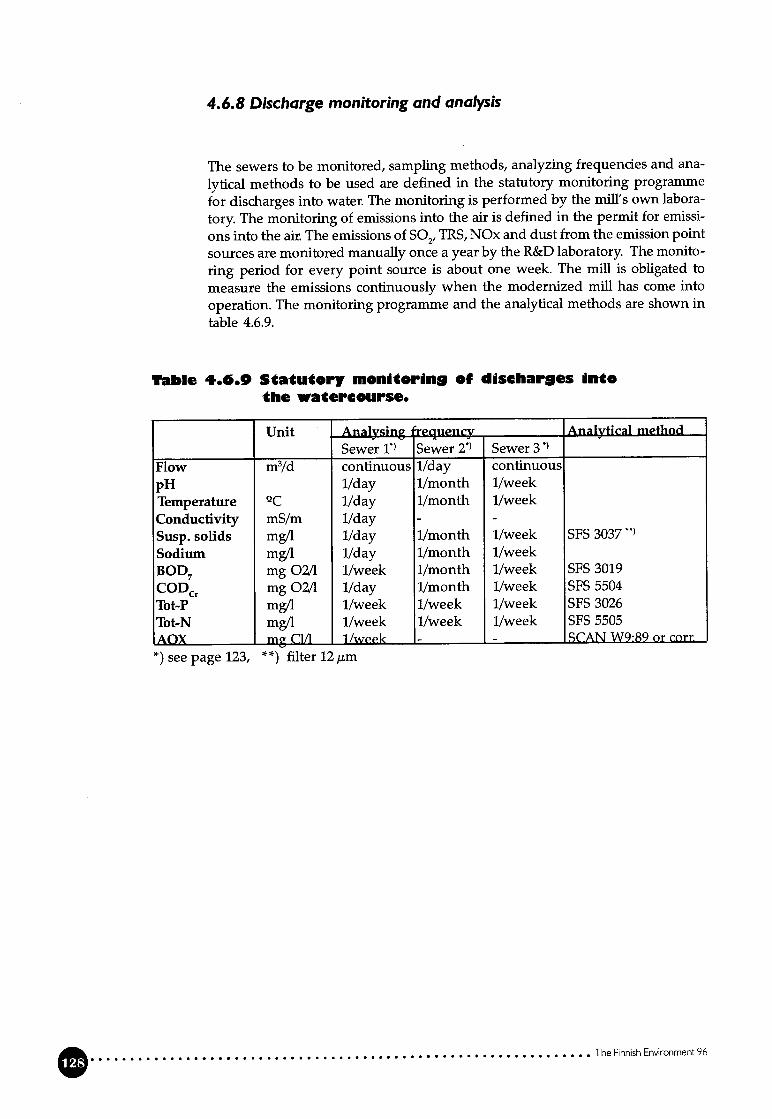
4.6.8 Discharge monitoring and analysis
The sewers to be monitored, sampling methods, anayzing frequencies and ana
lytical methods to be used are defined in the statutory monitoring programme
for discharges into water. The monitoring is performed by the mffl’s own labora
tory. The monitoring of emissions into the air is defined in the permit for emissi
ons into the air. The emissions of S02,TRS, NOx and dust from the emission point
sources are monitored manually once a year by the R&D laboratory. The monito
ring period for every point source is about one week. The muU is obligated to
measure the emissions continuously when the modernized mifi has come into
operation. The monitoring programme and the analytical methods are shown intable 4.6.9.
Table 4.6.0 Statutory mondtorin9 of discharges intothe watercourse.
Unit Analysing eguency Analytical niethod
Sewer Sewer Sewer 3 ‘
Flow m3/d continuous 1/day continuous
pH 1/day 1/month 1/weekTemperature 2C 1/day 1/month 1/weekConductivity mS/m 1/day - -
Susp. solids mg/1 llday 1/month 1/week SFS 3037”
Sodium mg/1 1/day 1/month 1/weekBOD7 mg 02/1 1/week 1/month 1/week SFS 3019
CODCr mg 02/1 1/day 1/month 1/week SFS 5504
Tot-F mg/1 1/week 1/week 1/week SFS 3026
Tot-N mg/1 1/week 1/week 1/week SFS 5505AOX m C1/1 1/week -_______ - SCAN W9:89 or corr.
*) see page 123, **)fflter 12 m
The Finneh Environment 96

This section discusses the costs of updating the process technology to achieveresource savings and reduced environmental impact.
The financial impact of different process techniques depends on the capitalinvestment required and on the operating cost. The operating cost depends one.g. the total costs of chemicals, energy, personnel, wood raw material and maintenance. A very important factor that affects the financial situation is the qualityrequirements of the final product.
5.1 Investment costs
The total investment costs for implementing a new process teclmique at an existing mifi is very much dependent on how the new process section fits into theexisting process configuration. Modernization in one process department maycreate the need for process modifications in other departments. In a totally newmiii ail the sections of the process are planned to give sufficient quality and withoptimal financial results.
Table 5.1.1 gives a summary of the investment costs for different processmeasures that have been discussed in chapter 3.3. The large ranges for the invest—ment costs are due to variations in the configurations of existing milis and theneed for additional modifications to the process.
5.2 Operating costs
The operating costs depend on the process configuration as a whole, on the properties and quality of the final product and, naturally, on how efficiently the process is operated. The applicafion of a new technique/piece of equipment at anexisting miii incurs installation and operation costs, but these costs may be recouped through savings (e.g. reduced raw material consumption, reduced waste generation, increased energy generation).
Because of the many factors that affect the operating costs, and the largedifferences in these factors between mifis, a more accurate picture of the impact isobtained by calculating the costs and the savings on a case-by-case basis than ifthe costs are generalized. Only in this way can special situations (e.g. limitingfactors like bottlenecks in the process) that may have a dramatic impact on theoperating costs be considered. An overail calculation of the material and energybalance of the process/the miii in the new situation is the basis for calculating thecosts accurately.
The Finnish Environment 96
Costs

Table 5.1.1 InvesCment costs for different processmeasures for a kraf( pulp miii
(production capacity 300,000 ADt/a, one-line mifi).
Investmentcosts1FIM mi11rrn
Dry debarking and modern chip-handling- a new complete plant 180-190- modernization of existing plant 30-90
Extended cooking (batch / continuous)- a new complete plant (batch - cont.) 230-300- modification of existing conventional plant toextended cooking (cont. - batch) 80-200
Brown stock washing- a new complete washing plant 80-140- additional washing stage iii existing washingplant 20-60
- C02-washing 0.1
Oxygen delignification before bleaching- 1-stage delignification 80-90- 2-stage delignification 90-100Enzyme treatment 0.5-1
Bleaching- a new complete TCF bleaching plant 220-300
(with peroxide - with ozone stage)
- additional bleaching stage- chelating stage 35-55- pressurised EOP-stage 50-60- ozone stage 70-90
Evaporation of BL- a new complete plant 100-120- additional high-density concentrator 20
Handling system for malodorous gases- strong gases 25-35-weak pss 15-20
The Finnish Environment 96

This section describes a newly built kraft pulp miii applying the most recent technologies to produce pulp with high-quality properties for a specfflc end use of thepulpO
6.1 General
The new kraft pulp mifi producing totally chlorine free pulp (TCF) started up inMarch 1996. The production capacity is 500,000 tonnes of bleached softwoodpulp (to be 600,000 tonnes by the end of the 1990’s). It is the largest one-line miiiin Finland. The consumption of wood wffl be about 3 million m3/a (80% pine, 20%spruce).
The mifi is situated adjacent to a paper miii, which currently produces 670,000tonnes of SC and LWC paper. A new LWC machine is scheduled to start up in1998.
The main product of the kraft pulp miil is bleached TCF softwood reinforcement pulp, which is used in the manufacture of wood-containing printing papers. The miii wffl also produce TCF pulp bleached to a higher brightness for usein the manufacture of woodfree fine papers.
The goal is to close the mull’s water cycles gradually by using bleaching fiitrates in pulp washing, which wffl resuit in a considerable reduction in effluentsfrom the mifi and m the consumption of fresh water. The kraft pulp mii has aclosed cooling water system because the availabifity of fresh water is limited, andit is the first kraft pulp miii in Finland to apply cooling tower technology.
High efficiency, not only in energy generation but also in the use of energy,has been one of the main rules in the design work. The pulp mffl’s energy surpiusis sold to the paper miii.
Part of the pulp production and the whole energy system are integratedwith the existing paper miii. The two milis utilize a joint raw water supply and anew chemical raw water purification and desalination plant. The existing activated sludge treatment was expanded at the beginning of the 1990’s to treat thewaste water from both mufis.
Up to 40% of the pulp production will be dewatered to a dryness of about30% and transferred to the paper mifi. The rest of the pulp production wffl bedewatered, dried in an airborne pulp dryer and transported to other paper milisin Finland or sold as market pulp in Europe.
The paper mifi is erecting a new fluidized bed power boiler in order to beable to burn the growing amount of biofuel available at the two mills. The backpressure power plant wffl generate power for mechanical pulping and steam forthe paper machines at the paper miil as weil as hot water for municipal districtheating.
The Finnish Environment 96
A new kraft puip miii

6.2 Process description
A block diagram of the kraft pulp miii is shown in figure 6.2.1.
Both the kraft pulp mifi and the paper mifi are committed to decreasing their
nominal water consumption. The starting level for the kraft pulp miil is 15 m3 of
fresh water per tonne of bleached pulp. The aim is to reduce the water consumption to 5-10m3/tonne of pulp by the end of the 1990’s.
The fresh water consumption has been minimized and water is recycled
wherever possible, starting with dry debarking in two drums. The bark is dried
by pressing, shredded and utilized as biofuel.The mifi is designed to receive wood both as logs and as sawmill chips. The
chippers, screening and reclaiming of chips are designed to produce uniform
chips from batch to batch. Uniform chips reduce the need for chemicals and the
cooking and bleaching conditions can be kept more stable. This helps to maintain
fibre strength. Screemng rejects, sawdust and large pieces of wood are removed
and used as biofuel. No water is used in the chip handling.The cooking plant consists of ten batch digesters. The cooking process is of
SuperBatch type. After chip fihling, the chips are impregnated with black liquor.
The organic substances dissolved in the cooking liquor are displaced from the
digester with washing-plant fiitrate, and the hot liquor is led to the black liquor
accumulators. The pulp is pumped into the discharge tank. Hot liquor from theaccumulators is utilized in the next cooking and for white liquor heating. Finally,
the black liquor is cooled to below 1000 C before it is pumped to the evaporation
plant. The heat exchangers supply most of the hot water required in the mifi.
Delignification in cooking is extended (Kappa —20) to meet the requirements
of TCF-bleaching. The well-performed impregnation of the chips guarantees a
low Kappa variation and low shive content in the brown stock. Because chips are
The Finnish Enqronment 96
EDTA- jSO4. H2S04- Peroxide 0x J Ozonestation 1 station station station station generation
T 7
Alkaline fiitrate
Figure 6.2.1 Block diagram of the kraft pulp miii
FibreWaterChem. rec. - - - -
ChemicalEnergy — - -
Waste waterGases

cooled to below boiling point before being pumped from the digester to thedischarge tank, the fibres are not damaged, the flashing of hot liquors is minimized and the liberation of malodorous gases is under control.
The washed and screened pulp is oxygen-delignified in two stages to a Kappa of < 10 and bleached. Only oxygen chemicals are used as bleaching chemicals(oxygen, hydrogen peroxide and ozone). Chelating agents and an acid wash areused in the bleaching to remove metais and prevent the hydrogen peroxide fromdecomposing. The alkaline bieaching ifitrates are led counter-current towardsthe brown stock washing. Acid ifitrate cannot yet he recovered because of themetal content and is discharged into the effluent treatment. The bieaching is totally based on the medium- consistency technique. The pulp is bleached to between 85 and over 88% ISO brightness.
The weak biack liquor from the cooking piant is evaporated in a seven-effectevaporation plant and concentrated to a dry-solids content of over 80%. The highdry-solids content facilitates the controi of the combustion tri the recovery boilerand keeps the emissions of S02very low.
The nominal capacity of the recovery boiler is 3,000 tonnes of dry solids perday and the steam capacity is 120 kg/s.
Three parallel three-field electrostatic precipitators separate the fly ash fromthe flue gases prior to venting into the air via the central stack (120 m).
The recovery boiler operates at an eievated pressure and temperature compared with conventional recovery boilers. The pressure has been eievated to 90bars and the temperature of the superheated steam to 490° C. The high pressuremaximizes energy efficiency in the generation of power.
The turbine generator (92 MW installed) generates excess power comparedwith the eiectrical power consumed at the puip miii. The surpius is estimated tobe in the range of 50% of the total generation. The major part of the back-pressuresteam is used in the process and the rest is sold to the paper miii.
The smelt from the recovery boiler is dissoived and pumped into the causticizing plant. The vent gases from the smelt dissolver are treated by aikalinewashing.
The causticizing piant is conventional, but the plant iayout allows for changes to the process. The lime mud is dried from 80% to 100% dryness before beingburnt.
Part of the sulphur in the fuel and malodorous gases that are burnt in thelime kun is bound in the lime, whereas the rest is recovered from the flue gases inthe alkaline scrubber following the electrostatic precipitator.
Soap dissolved from the wood is separated from the biack liquor at the top ofthe impregnation liquor tank and from the evaporation liquor tanks. The soap isrefined in the tali oil plant.
The pulp miil has a very comprehensive recovery system for malodorousgases. Ali the equipment and tanks which couid possibiy release malodorous gases in the cooking, brown-stock washing, evaporation and caustidzing are connected to the system. Ali strong and weak malodorous gases are burnt. Weakgases are treated in direct contact scrubbers and burnt in the recovery boiler astertiary combustion air. The strong malodorous gases from cooking and evaporation are normally burnt tri the lime kiln. The combustible malodorous gases replace part of the fuel oil, reducing the consumption of fossil fueis. Tri the situationwhen the lime kun is not in use there is a separate furnace equipped with a separate boiier. Tri the case of a breakdown in the operation of the recovery boiler,weak malodorous gases are washed with alkaline washing liquor before beingemitted into the air via the central stack.
The Rnnish Enronment 96

The old treatment plant for fresh water at the adjacent paper miii has been rebuilt
for both capacity and quality reasons. The new process is based on two-stage
flocculation with ferrisulphate and oxidizing treatment before firial sand filtrati
on.When the consumption of ftesh water is being decreased at a pulp miii, it is
essential to utilize the condensates from the evaporation of the black liquor. Clean
and foul condensates are collected separately. Foul condensates are purified by
stripping. Both condensates are used as wash water. An advantage in using condensates in TCF bleaching is the absence of metais, although they contain volaffle
organic substances. The proportion of clean condensates is high in the pulp mifidue to internal stripping and distifiation in the evaporation umts.
It is essential that secondary energy is utilized in the consumption of bothenergy and fresh water. The secondary condensate from the stripper is usedinstead of warm water in the fibre line and in the causticizing plant. Warm wateris used only in places where the water needs to be especially clean. The hot waterproduced m the process is used not only to heat the process but also to heat thebuildings m the winter.
Cooling and heating water is collected into a common network and cooledin a cooling tower. The cooling tower supplies cold water for the mifi. The additional cold water is received from the paper mffl’s water plant.
The estimated total heat consumption by the pulp mifi is below 11 GJ/tonneof pulp produced. The power consumption is estimated at 600 kWh/t.
The new circulating fluidized bed boiler at the paper mifi (start-up in the
summer of 1996) wffl use bark and wood residues from the pulp miil and the
paper miii, biosludge and, additionally, peat and coal when required. The steam
wffl be used in the paper mifi.The total investment cost of the kraft pulp miii was FIM 2.5 bilhion.
6.3 External treatment
The pulp mifi effluents are treated in an activated sludge treatment plant together with the effluents from the paper miii. The treatment plant consists of aprimary clarifier, activated sludge treatment, a secondary clarifier and sludge
treatment.Excess biosludge is thickened lii decanting tanks, mixed with priinary slud
ge and dried with screw presses to a dry-solids content of over 40%. The dewate
red sludge is burnt together with bark and other biofueis in a fluidized bed boilerat the paper mifi and later on in the new circulating bed boiler at present being
constructed for generating energy for the paper miii.
The Finnish Environrnent 96
Discussion................................................
Finland is a country distinguished by its remote location, sparse population andvast forests. A shortage of other basic raw materiais early on focussed the industrial effort on wood-based products. The relative remoteness of continental industrial centres and their supply of machinery encouraged the rapidly evolvingFinnish chemical forest (pulp, paper and board) industry to establish its ownmachine shops. Later a diverse chemical and electronics industry supplying thepulp and paper industry with agents, additives, components and control systemssprang up. Today these support industries are giobal players, supplying the mternational pulp and paper industry worldwide. Together with the basic forestindustry they form the heart of the Finnish industrial complex.
The importance of the forest industry for the development of the countrymakes its only natural that Finland has been a forerunner in forging internationalagreements that secure the well-being of the forests and the natural surroundings in general by adherence to sound environmental protection practices. Consequently, ail Finnish pulp and paper companies have signed the ICC accord onthe principles for sustainable development, and they adhere to these principlesin their everyday operations.
Forewarned by the devastating results of the uncontrolled logging practicesduring the peak of the wood tar and charcoal production era, the authorities andthe forest owners realised that controlled and systematic forestry principles hadto be applied to secure the long-term supply of the raw material. Early legislationregulates cutting rights and lays down the responsibility for regenerating harvested forests. The Finnish forests, over sixty per cent of which are owned byrelatively small private owners, are being managed by a web of voluntary forestassociations. These associations promote members’ rights and maintain a comprehensive training programme. It has, therefore, been easy to implement newforestry practices like biodiversity and landscape protection as they have emerged from new knowledge gained and society’s requests for a wide range of usesfor the forests. These new practices have also met with success. It should be remembered that in Finland “every man’s right” to move freely about in the forestand collect berries and mushrooms has been acknowledged since ancient times.Thanks to the early protective measures and the progressive forestry principles,there is today more wood in the Finnish forests than before the establishment ofthe pulp and paper industry.
Despite chaflenging adverse economic factors like generally small population centres and the long distances between them, the collection of waste paperand board and the reuse of recycled fibre are at a high level in internationalterms in Finland.
Despite the low population density and the abundant availabifity of goodquality water, the Finnish pulp and paper industry has taken a very responsiblestand on environmental issues. While doubling the production, the industry hasbeen able to reduce the discharges of pollutants into water to one- tenth of thelevel thirty years ago and the emission of sulphur into the air to a mere fraction of
The Rnnish Environment 96

the past. The present high standards of environmental protection have beenreached through an intensive investment programme in improved processes andpollution abatement techniques.
Ali Finnish pulp and paper mifis must have an environmental permit, speci
fying the limit on discharges and emissions into water and the air as well as thegeneration of solid waste. A ftuitful dialogue between the authorities and theindustry has led to a situation where Finnish industry has to meet limits that areoften very tight but attainable within reasonable costs. In Finland there is a general striving towards a more holistic view on environmental protection issues inorder to avoid the adverse situation where pollutants are transformed from oneform into another or from one receiving body into another. Finland also adheresto the principles of fi.ill openness, standardized testing procedures and reportingpractices. In Finland the compulsory discharge measurements performed by themifis are public knowledge. This allows for a fair comparison between the Finnish milis with regard to their environmental impact and the efficiency of theirpollution abatement actions.
It is most unfortunate that there stiil is a lack of international standards formaking environmental performance records public. The useful benchmarking ofthe industry’s performance in different European countries could be based onthem.
It appears that before the BAT Reference Document can be used for the European pulp and paper industry there has to be an agreement on the giobal harmonization of the procedures for sampling and testing pollutants as well as onhow to report the results and the related operating conditions. Further, there has
to be agreement or an understanding on how different geographical locationsand cimatic conditions affect factors like energy and water consumption.
In general, there is often a good correlation between efficiency, and especial
ly resource-usage efficiency, and pollution abatement. Therefore, the industryhas put m a lot of effort to bring down the specific usage of wood, additives,water and energy. The higher overail efficiency is a resuit of more functional products, improved processes and equipment, and new control and managementschemes. As a consequence, pollution abatement is increasingly moving awayfrom “end-of-the-pipe” solutions towards process internal solutions, such as ener
gy recovery and reuse, and the closed loop operation of process water systems. It
now, therefore, seems reasonable to suggest that in the establishment of a BATReference Document for the pulp and paper industry, more effort should go intospecifying the sought-for resuit, and the industry should be left with sufficientfreedom on how to reach these results.
Recently market forces in the form of consumers’ awakened interest into the
environmental impact of the producfion of the goods they use have proved to bea strong mofivator for the industry to use sound production methods. With theincreased use of Eco-labeffing of products the authorities need to provide unbi
ased information to support the consumers in their buying decisions and execute
supervision so that this market place-related positive motivator leads the deve
lopment in a direction beneficial for ail parties.The special stature of the pulp and paper industry in Finland has attracted
both good human resources and sufficient capital to support the extremely st
rong growth it has undergone during the lasI thirty years. In that time span the
producfion capacity has more than doubled, the more compefitive kraft (sulpha
te) process has entirely replaced the sulphite process in chemical pulping, ther
momechanical pulping has overtaken groundwood in mechanical pulping, and
paper and board manufacturing has moved from commodity to higher-value spe
The Finnish Environment 96

ciality grades. Today the Finnish pulp and paper industry is characterised by integrated production, large production units, specialized products, customized processes and top-class, modern equipment.
Integrated production facilitates a more complete usage of the different woodspecies as they grow in the forest. Likewise, the potential best usage of a tree fordifferent products - lumber, plywood, pulp, paper or board - can be realized.Further, the part of the wood that does not end up in a product can be used forenergy production. Actually, only the ash of the portion of the wood used forenergy production, well below one-tenth of one per cent of the original weight ofthe wood, needs to be disposed of. The ash can be brought back to the forest asfertilizer or used for soil binding purposes. In the integrated production of pulpand paper the water usage can be more efficient than in two separate installations, and naturally there wffl be a significant reduction in the cost of waste watertreatment installations. In the most usual cases excess process water in the paperor board manufacturing can be brought back and reused in the pulp making.Even greater is the synergy in relation to reduced energy usage. The excess heatand power generated in the kraft mifi is used advantageously in the paper orboard mifi as is the heat in the process steam recovered in the TMP plant. In theintegrated production plants the use of back-pressure generation, which is sotypical of the Finnish forest industry, provides great savings.
The significance of the size of the production units basically lies in reducedcapital and operating costs per unit of product. Though the cost of the main process machinery need not be lower, the cost of auxiliary equipment and supportprocesses such as pollution abatement facilities is reduced. From the simple factthat the larger units in most cases are also more modern, it follows that the largerproduction units are more efficient when it comes to both productivity and resource usage. The inherent value of the large production units is further enhancedwith the on-going mergers of the forest industry companies into larger corporations. The larger compariies can better implement marketing and sales effortsthat wil facffitate long, continuous, single grade runs on the large paper andboard machines, which wffl greatly enhance the overail efficiency.
The move towards more specialized products has been compulsory in orderto offset adverse competitive factors like distance to the market and the lack ofsufficient domestic energy resources. The Finnish industiy’s switch from being amajor supplier of market chemical pulp to a supplier of mainly paper and boardhas been a remarkable change. In addition, the remaining shipments of kraft andmechanical pulps represent products with properties taiored for specific enduses. The rapid development of new specialized products is the resuit of the advanced academic training programme in pulp and paper making m Finland andextensive research taking place in the industry’s own central Finnish Pulp AndPaper Research Institute facilities, universities, suppliers’ piot plants and, to amajor degree, also at the milis. The new products better fulifi the end users’ requirements, and this while fewer resources, with the exception of power consumption in some grades, have been used in the manufacturing stage.
The higher power consumption is a consequence of the extensive use of TMPpulping in the Finnish paper industry. The high power consumption is offset bythe reuse of the heat in the process steam efficiently recovered in the TMP plantand the better raw material efficiency stemming from the reduced use of chemical pulp iii the prinhing paper and board grades in question. It is remarkable thatboth pressurised grinding, PGW, and high-pressure refiner pulping, TME weredeveloped in Finland with its abundance of forest, when the main goal has beento reduce the use of chemical pulp.
The Finnish Environment 96

Meanwhile, there have also been great improvements in the field of chemicalpulping in Finland. Within kraft pulping the batch cooking technology has beenrevitalised to yield a process with superior heat economy and producing a longfibre pulp with unique sfrength properties. New bleaching sequences have beendeveloped so that in the most modern kraft miii the discharge of process waterfrom the bleaching plant is only 5m3/tonne of pulp. Similar spectacular developments in the chemical-recovery cycle include increasing the dry matter of theblack liquor to be fired in the recovery boiler to over eighty per cent. This hasfurther improved the favourable energy balance of modern kraft mufis and ail buteliminated the emission of sulphur compounds from the recovery boiler into theair. The coilection of malodorous gases has in several miis been taken so far thatthe remaining occasional small outbursts are no longer considered harmful to theenvironment.
One other customized process is the use of back-pressure turbines for thegeneration of power. The process takes advantages of the need for low-pressuresteam in the drying of pulp, paper and board. Lumber and plywood drying arealso frequently hooked up to the same steam supply as well as the district heatingsystem of some nearby municipality.
In the field of pollution abatement the activated sludge technology for thetreatment of discharged process waters has been refined to the point where theBOD removal efficiency is extremely high and also the removal of phosphorusand nitrogen is significant. Lately, new technologies such as membrane filtrationand vacuum evaporation have come into use in the internal purification of process waters, bringing the concept of closed Ioop operation one step nearer.The equipment used in the wood room has lately undergone a very rapid development. Today the wood room can be operated without the discharge of processwater by using the dry debarking process. The quality of the chips and, evenmore iinportant, the consistency of the quality has greatly improved the stabffityand efficiency of the downstream processes.
In the different washing operations in the pulp miii more efficient wash presses and displacement washers have been introduced. This has reduced the specific consumption of water and increased the amount of dissolved solids and chemicals being captured for regeneration and energy production. The equipmentfacffitaiing the revolutionary change to the medium-consistency pumping of pulpsiurries from the conventional low-consistency was developed by Finnish scientists. The new technology has reduced the amount of water being pumped aroundin certain pulp and paper miii departments, with a factor of four greatLy reducingthe energy consumption.
The Finnish electronics industry has developed advanced new sensors andcontrol systems for the pulp and paper-making processes, which, in turn, haveincreased the overail efficiency.
To sum up, it can be said without exaggeration that the most specialized andmodern sectors of the Finnish pulp, paper and board industry represent state-ofthe-art knowledge and technology and can well serve as an example to othersstriving for efficiency and minimal environmental impact at their own mifis.
The Finnish Environment 96

Appendix 1
Standard analytical methods
Waste water
Standard methodsSFS Corresponding method
TSS(GFA) SFS 3037BOD7 SFS 3019 SS 02 81 43 (1. ed.)
SFS 5508 SS 02 81 43 (2. ed.)
CODcr SFS 5504, Dr LangeSFS 3020 SS 02 81 42
CODMfl SFS 3036 SS 02 81 18Tot-P SFS 3026 SS 02 81 27Tot-N SFS 5505AOX SS 1)2 81 04. SCAM W9:89. DIN 38409
SFS Finnish Standards AssociationSS Swedish standard
Emissions into the air
Standard methodsSFS Corresponding methnd
Dust SFS 3866S02 SFS 5265 SS 02 84 21TRS SFS 5727 EPA nr 16ANO SS 02 84 25, ISO-CD 10849, EPA nr 7
The Rnnsh Environment 96

Appendix 2
Chlorine dioxide generation methods in use in Finland
vIATHIESON R3 R3H R5 R6 R7 R8 LURGIR6
Input chemicals(t/t C102)NaC1O2 1.75 1.68 1.68 1.75 1.68 1.65NaC1 1.15 0.35 0.03 1.08H2S04 1.30 1.73 0.80 0.40 1.10HCI 0.70 1.40S02 0.75 0.40CH3OH 0.15C12 0.80EI power (MWh) 8.50By products — — —
(tlt C102)Na2SO4 1.20 2.30 1.20 1.60H2S04 1.60Na3H(S04)2 1.30C12 0.00 0.70 0.70 0.80 0.30 0.20 0.10H2 0.05NaC1 0.95NaOH — — 0.70
The chemical reactions for chlorine dioxide generation
Generation method Chemical reactionMATHIESON S02+2NaC1O3+H2S04-> 2C102+2NaHSO4R3 NaC1O3+NaC1+H2S04-> C1O+YC12+Na2SO4+H20R3H NaC1O3+HC1+‘,4H2S04 -> C102+½C12+ VzNa2SO4+H20R5 NaC1O3+2HC1 -> C102+¼C12+NaC1+H20R6 c) NaC1O3+2HC1 -> NaC1+C102+½C12+H20
a) NaC1+3H20-> NaC1O3+3H2R6-LURGI b) H2+C12-> 2HC1R7 NaC1O3+HC1+‘AH2SO4 -> C102+‘/2C12+½Na2SO4+H20R8 6NaC1O+4H2S04+ CHOH- > 6C102+2NaH(SO4)2+5H20+ C02
The Finneh Enironment96

The Finnish pulp and paper milis 1995
Appendix 3
(Finrish Forest Industries Federation)a: number of lines, b: number of machines, c: annual production (1,000 t).
Chemical pulp Mechanical pulp Paper____ Boarda c a c b c b c
A Ahlstrom CorporationAhlstrom Alcore 1 47Ahlstrom Kauttua 4 58
Enso GroupAnjalankoski Milis 2 420 3 425 1 152Corenso/ Varkaus 1 64Corenso/Pori 1 74Heinola Miii 1 234 1 231Imatra Milis 3 671 3 238 4 703Kotka Milis 1 111 1 80 2 241Oulu Milis 1 325 1 250Summa Milis 2 339 3 412Varkaus Milis 1 181 2 270 4 480Veitsiluoto Milis 1 296 1 82 4 652Enocell Oy 2 479Kemijärven Sellu Oy 1 178Pankakoski Boards Oy 1 23 2 74Tervakoski Oy 5 99
Keräyskuitu Oy (recycled fibre) 1 60Metsä-Botnia OyAb
Kaskinen Miii 1 394Kemi Mills 2 506 1 298
Metsä-Serla OyKangas Miil 2 121Kirkniemi Mills 2 117 2 329Kyro Milis 2 82 1 81 1 73Lielahti Miil 1 106Tako Mills 1 61 3 158Aänekoski Mills 1 455 1 32 1 112 1 97Savon Sellu Oy 1 213 1 224Serla Oy 5 106
Myilykoski Paper Oy 1 220 4 479Nokian Paperi Oy 3 80Stromsdal Oy 1 19 1 40Sunila Oy 2 319UPM-Kymmene Corporation
Joutseno Puip 1 316Jämsänkoski 2 392 4 704Kaipola 340 3 603Kajaani 2 419 3 498Kaukas, Lappeenranta Milis 2 462 2 143 2 466Kaukas, Voikka mills 1 245 4 454Kymi Paper Milis 2 507 1 20 5 561Lohjan Paperi 2 52Rauma Milis 2 325 3 684Simpele Milis 1 72 1 43 1 125Tervasaari Mills 1 171 3 211Wisaforest 2 527 1 134
Total production 5898 4314 8634 2359Number of lineq and average size 24 250 30 140 2& J.i2 ZL______
The Finnish Environment 96
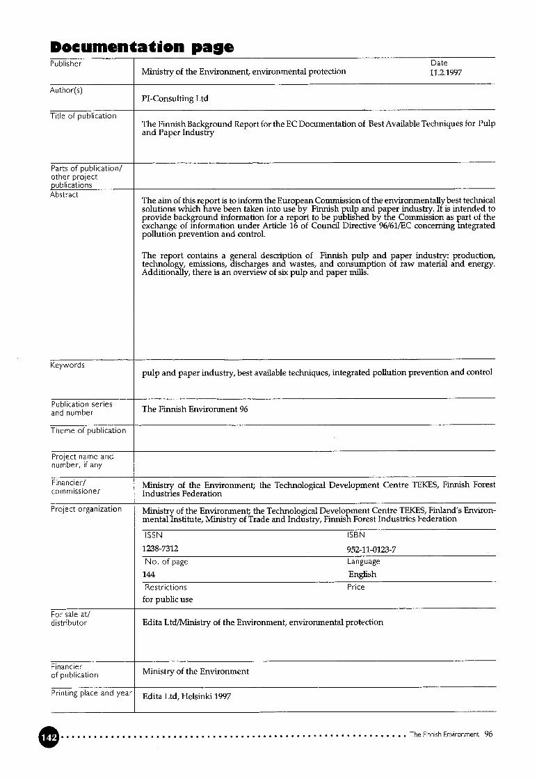
Documentaton paePublisher Date
Ministry of the Environment, environmental protection 11.2.1997
Author(s)PI-Consulting Ltd
Title of publicationThe Finnish Background Report for the EC Documentation of Best Available Techniques for Pulpand Paper Industry
Parts of publication/other projectpublicationsAbstract
The airn of this report is to inform the European Comnussion of the environmentally best techmcalsolutions which have been taken into use by Finnish pulp and paper industry. It is intended toprovide background information for a report to be published by the Commission as part of theexchange of information under Article 16 of Council Directive 96/61/EC concerning integratedpollution prevention and control.
The report contains a general description of Finnish pulp and paper industry: production,technology, einissions, discharges and wastes, and consumption of raw material and energy.Additionally, there is an overview of six pulp and paper milis.
Keywordspulp and paper industry, best available techniques, integrated pollution prevention and control
PubIicaton seriesand number The Finnish Environment 96
Theme of publication
Project name andnumber, ifany
Financier/ Ministry of the Environment; the Technological Development Centre TEKES, Finnish Forestcom m issioner Industries Federation
Project organization Ministry of the Environment; the Technological Development Centre TEKES, Finland’s Environmental Institute, Ministry of Trade and Industry, Finnish Forest Industries Federation
SSN ISBN
1238-7312 952-11-0123-7No. of page Language
144 English
Restrictions Price
for public use
For sale at/distributor Edita Ltd/Ministry of the Environment, environmental protection
tion Ministry of the Environment
Printing place and year Edita Ltd, Helsinki 1997
The Finnish Environment 96

Kuvailulelitijulkaisija julkaisuaika
Ympäristöniinisteriö, ympäristönsuojeluosasto 11.2.1997
Tekijä(t)Projekti-Insmöörit Oy
Julkaisun nimi Suomen taustaraportti Euroopan komissiolle parhaasta käytettävissä olevasta teknilkasta massa- japaperiteollisuudessa
julkaisun osat!muut saman projektintuottamat julkaisutTiivistelmä .
Taman raportin tarkoituksena on antaa Euroopan komissiolle tietoa Suomen massa- japaperiteollisuudessa käyttöön otetuista ympäristönsuojelun kannalta parhaista teknisistä ratkaisuista. Raportti on tarkoitettu taustamateriaaliksi komission toimeksiannosta laadittavalle raportille, joka on osa Euroopan Yhteisöjen neuvoston direktiivin 96/61/EY ympäristön pilaantumisenehkäisemisen ja vähentäniisen yhtenäistäminen, artikian 16 mukaista tiedonvaihtoa.
Raportissa kuvataan yleisesti Suomen massa- ja paperiteollisuutta, sen tuotantoa, teknologiaa,päästöjä veteen, ilmaan ja jäfteiksi sekä raaka-aineiden ja energian kulutusta. Ympäristönsuojelunkokonaisvaltainen tarkastelu on tehty lisäksi kuudesta tehtaasta.
Asiasanat Massa- ja paperiteoffisuus, paras tekniikka, päästöjen yhtenäinen ehkäiseminen ja vähentäminen
julkaisusarjan nimi Suomen Ympäristö 96ja numero
Julkaisun teema
Projektihankkeen nimija projektinumero
Ympäristöministeriö, Teknologian Kehittämiskeskus Tekes, Metsäteoffisuus ry
Projektiryhmään. Ympäristömmisteriö,Metsäteoffisuus ry, Suomenympäristökeskus,Teknologiankehittämiskeskus
kuuluvat organisaatiot Tekes, Kauppa- ja teollisuusministeriö
ISSN ISBN
1238-7312 952-11-0123-7
Sivuja Kieli144 Englanti
Luottamuksellisuus Hinta
Julkinen
julkaisun myynti! Oy Edita Ab/Ympäristöministeriö,ympäristönsuojeluosasto
j ulkaisun kustantaja Ympäristö mnistenö
Painopaikka ja -aika Oy Edita Ab, Helsinki 1997
Suomen yrnpä1stö 96

PresentaionsbladUtgivare Datum
Miljöministeriet, miljövårdsavdelningen 11.2.1997
Fö rfattareProjekti-Insinöörit Oy
Publikationens titelBakgrundsrapport till Europeiska Umonens kommission av bästa tillgängliga teknik inom finskamassa- och pappersindustrin
Publikationens delar/andra pubiikationerinom samma projektSam mandrag
Syftet med denna rapport är att informera kommissionen om de i miljövårdshänseende bästatekniska lösriingar som tagits i bruk i massa- och pappersindustrin i Finland. Rapporten är avseddsom bakgrundsmaterial för en rapport som kommissionen kommer att låta utarbeta som en del avinformationsutväxlingen en]igt artikel 16 i Europeiska gemenskapernas råds direktiv 96/61/EG omsamordnade åtgärder för att förebygga och begränsa föroreningar.
Rapporten innehåller en ailmän beskrivning av massa- och pappersindustrin i Finland, produktionen, tekniken, utsläppen i vatten och luft samt avfallet, vidare förbrukningen av råvara och energi.Dessutom ingår i rapporten en övergripande granskning av miljövården i sex fabriker.
Nyckelord . . . . ..
Massa- och pappersindustri, bästa tekmk, integrermg av forebyggande ochmmskning av utslappen
Publikationsserieoch nummer Fmlandsmiljo96
Publikationens tema
Projektets namn ochnummer
ivare Miljöministeriet, Teknologiska utvecklingscentralen TEKES, Skogsindustrin rf
2erMilj öministeriet, Teknologiska utvecklingscentralen TEKES, Finlands miljöcentral, Handeis- ochmdustrimmistenet, Skogsindustrm rfISSN ISBN
1238-7312 952-11-0123-7
Sidantal Språk144 Engelska
Offentlighet Pris
0ffentligBeställningar/d istribution Oy Edita Ab/Miljöministeriet, miljövårdsavdefriingen
FörläggareMiljoministenet
Trycke ri/tryckningsort och -år Oy Edita Ab, Helsingfors 1997
Miljön i Finland 96

The Finnish Environment
ENVIRONMENTALPROTECTION
The Finnish Background Report for the EC
Documentation of Best Available Techniques
for Pulp and Paper Industry
The purpose of this report is to carry out the Finnish contribution to the
exchange of information in the Council Directive 96/61/EC concerning
Intergrated Pollution Prevention and Control, article 16, and to the
preparation of the Reference Document of the European Commission on
the Best Available Tehniques for Pulp and Paper Industry.
In the report, the manufacturing of pulp, paper and board grades which
are most important for the Finnish pulp and paper industry are discussed
taking into account production capasities, the used process technoiogies
and their effects on the discharges and emissions, solid waste generation
and consumption of raw material and energy.
The general description of Finnish pulp and paper industry is
supplemented with more detailed descriptions of six Finnish pulp and
paper milis representing different types of products and production set
ups. The process technology of a new kraft pulp miii which started in the
spring of 1996 is also described.
ISBN 952-11-0123-7ISSN 1238-7312
r
r
O O 0
EDITA Ltd.P0 Box 800,00043 EDITA, telephone (09) 566 01CUSTOMER SERVICEStelephone (09) 566 0266, fax (09) 566 0380 9 789521 101236
O 0 O 0 O 0 0 0 O 0 O 0 O 0 O O O 0 O 0 0 O O
MINISTRY OFTHE ENVIRONMENT P0 Box 399, 00121 HELSINKIO