Next Gen Optical Transport: From 100 Gb/s to 1 Tb/s and Beyond

The Evolution of Next-Gen Optical NetworksTerabit Super-Channels and Flexible Grid ROADM ArchitecturesCable operators have made significant progress in migrating from 10 Gb/s optical transport waves to 100 Gb/s waves in their core networks. 100G waves allow 8 Tb/s or more of capacity to be carried on traditional fiber using the standard 50 GHz C-Band ITU-T G.694.1 grid. However, bandwidth growth projections already indicate that 8 Tb/s of capacity per fiber will be insufficient in the near future and that the operational costs of deploying so much capacity in 100G increments can be high. To address the emerging capacity requirements and to achieve better operational efficiency, next generation optical networks will utilize a flexible grid channel plan (variable-width optical super-channels) and terabit scale super-channels implemented with the appropriate modulation, depending on reach requirements, and incorporating software controlled optical switching functions.
WHITE PAPER

Page 2
The standard ITU-T grid has built-in guard bands between each optical channel to allow filtering and switching. These guard bands waste up to 25% of the fiber’s capacity. The solution to this problem is the elimination of the ITU-T grid as we know it and the migration to terabit scale super-channels, which can support up to 24 Tb/s of capacity per fiber, but which are wider than the classic fixed grid frequency slots. Using a flexible optical grid, which eliminates most of the inefficient optical guard bands and which allows optical spectrum to be allocated to waves as needed in 12.5 GHz increments, much greater spectral efficiency can be achieved on today’s fiber. Additionally, using advanced software-defined modulation techniques with coherent detection implemented in a DSP, it is also possible to provision the modulation format (BPSK, QPSK, M-ary QAM) in software on a lambda by lambda basis, allowing operators to optimize their networks in the future for reach versus total capacity.
The industry has already begun to introduce optical super-channels in which multiple coherent carriers are digitally combined on a single line card to create an aggregate channel of a higher data rate. However, managing next-generation super-channels with the existing network infrastructure is a challenge since flexible grid super-channels will occupy variable spectrums on the ITU-T grid depending upon the modulation scheme used (BPSK, QPSK, 8QAM, 16QAM, etc.). This drives the evolution of, and network migration to, flexible-grid ROADMs (reconfigurable optical add/drop multiplexers), which can switch any amount of optical spectrum in increments of 12.5 GHz.
Traditionally, optical networks have operated on the wavelength level and have used ROADMs to provide optical switching of these wavelengths. Since most client services remain at 10 Gb/s, muxponders (multiplexing transponders) are typically used to aggregate these services in a point-to-point fashion onto wavelengths. But as the line side transport migrates to super-channels, this muxponder based architecture can become highly inefficient if it lacks the capability to groom lower rate services into super-channels and hence can lead to low utilization of deployed bandwidth.
To alleviate this problem, next-generation networks will best be built with a multi-layer switching architecture (converged digital and optical switching), which integrates digital OTN switching with ODU0 (Optical channel Data Unit at ~1.25 Gb/s) granularity and super-channel based optical switching. OTN based digital switching enables efficient packing of the super-channel, reducing stranded capacity. Once filled, the optical super-channels can be switched using flexible grid ROADMs for operational simplicity and a greater degree of flexibility. A key element of this architecture is that the OTN digital switching and the ROADM super-channel switching are controlled by a unified, carrier-grade control plane.
This paper provides a technical overview of flexible grid DWDM and terabit optical super-channel implementations and explores the underlying technologies. A more in-depth discussion is presented on the various proposed super-channel implementations providing modulation, cost,

and technology timeline trade-offs. The paper then provides a technical overview of flexible grid ROADMs and converged OTN/flexible grid switching architectures in the context of transporting variable bandwidth optical super-channels.
Flexible Grid Terabit Super-ChannelsITU-T G.694.1 (Edition1) C-Band DWDM Channel Plan
To maximize the use of fiber spectral capacity and thereby lower CapEx costs, most metro and LH (long-haul) optical networks today utilize DWDM (Dense Wave Division Multiplexing, an optical version of frequency division multiplexing) to transport multiple waves over a single fiber. The ITU (International Telecommunication Union) long ago standardized a fixed DWDM channel plan for the C-Band, where most DWDM systems now operate.
The traditional ITU-T channel grid defines fixed optical channels spaced at 25, 50, and 100 GHz, typically supporting 160, 80, and 40 optical channels, respectively, in the C-Band. If each of these channels is filled with a 10 Gb/s optical signal, the C-band will support 1.6, 0.8, and 0.4 Tb/s capacity, respectively, on a fiber pair (separate TX and RX fibers). Figure 1, below, shows the standard ITU-T grid channel assignments for 25, 50, and 100 GHz channel spacings. With each successive reduction in defined channel spacing, new channels are created between the existing channels, and the spacing is reduced by one half.
Using on-off keying (OOK) modulation, where light-on encodes a digital 1 and light-off encodes a digital 0 (or vice-versa), a 10 Gb/s encoded optical signal will readily fit into even the 25 GHz spaced channel plan. However, as the industry considered migrating to 100 Gb/s optical transport waves to achieve even better spectral efficiency, OOK modulation was not an option
Page 3
Figure 1: ITU-T G.694.1 C-Band DWDM Channel Assignments
191.
6
191.
8
192.
0
192.
2
192.
4
192.
6
192.
8
193.
0
193.
2
193.
4
193.
6
193.
8
194.
0
194.
2
194.
4
194.
6
194.
8
195.
0
195.
2
195.
4
195.
6
195.
8
196.
0
40 λ - 100 GHz 80 λ - 50 GHz 160 λ - 25 GHz
40 λ
80 λ
160 λ
Frequency (THz)

due its higher spectral requirements and susceptibility to fiber impairments such as chromatic dispersion (CD) and polarization mode dispersion (PMD). Higher order modulation is required to increase the bits encoded per symbol and thereby allow the use of a lower symbol rate and hence reduce the spectral requirements. Because of its optimal balance between reach and capacity almost all 100G DWDM deployments today use PM-QPSK (Polarization Multiplexed, Quadrature Phase Shift Keying) modulation, which will support the use of 50 GHz spaced channels in the traditional ITU-T grid. At 50 GHz spacing and with 80 channels in the C-Band, a fiber pair will support up to 8 Tb/s of bi-directional transport capacity with 100G waves, a 10X improvement over 10G waves spaced at 50 GHz. Additionally, the coherent detection compensation techniques used with PM-QPSK modulation can offer significantly better optical performance than 10G OOK[1].
ITU-T G.694.1 C-Band DWDM Channel Plan Spectral Limitations
The original ITU-T C-Band channel plan was designed with built-in guard bands on the lower and upper edges of each optical channel. This was necessary to allow optical switching and multiplexing/demultiplexing of individual waves, which is essential for routing the waves to their destination as well as adding and dropping waves at their destination. However, these guard bands consume a considerable amount of spectrum, which cannot be used for actual payload transport, and this results in reduced utilization of the fiber’s inherent transport capacity.
To recover this capacity stranded in the guard bands, the industry is now migrating to optical super-channels, which are much wider than the traditional ITU-T grid channels, but which have no internal guard bands and are therefore more spectrally efficient. As an example, Figure 2, below, shows in the left diagram 1.2 Tb/s of transport capacity allocated across 12x100G waves using the standard ITU-T grid and its guard bands (the guard bands are highlighted in red). In this case, 1.2 Tb/s of transport capacity requires 600 GHz of optical spectrum for transport.
The diagram on the right side of Figure 2 shows the equivalent multi-carrier super-channel, which is in this example also implemented with 12x100G waves. Because the super-channel is always switched or multiplexed/demultiplexed as an integral whole, the guard bands between the internal waves of the super-channel are no longer needed and have been eliminated. Guard bands are now only required at the lower and upper edges of the super-channel itself. In this case, 1.2 Tb/s of transport capacity only requires 462.5 GHz of optical spectrum for transport,
Page 4
Conventional Per-ChannelDWDM Filtering
Multi‐CarrierSuper-Channel
1.2 Tb/s600 GHz
1.2 Tb/s462.5 GHz
12 x 100G Waves 12 x 100G Waves
Figure 2: DWDM Guard Bands and Spectral Requirements For Standard ITU-T Grid Channels and Multi-Carrier Super-Channels
which is a 23% reduction of required optical spectrum when compared to transmission using traditional ITU-T grid channels. From an optical channel perspective, this is a transition from 12 discrete 50 GHz channels to one 462.5 GHz super-channel. Of course, super-channels may be implemented in many different ways, and this will be discussed later in this paper.
Because super-channels are spectrally wider than the traditional ITU-T grid fixed channels, operators deploying super-channels will need to migrate to optical line systems, which support flexible-grid channel plans. Fortunately, the ITU has recently standardized such a flexible grid channel plan under ITU-T G.694.1 (Edition 2). This second edition provides reverse compatibility with the first edition, but also supports the allocation of bandwidth to flexible-width channels in 12.5 GHz increments.
Modulation Formats and Coherent Detection
Most 100G optical transport systems today use PM-QPSK modulation with coherent detection. Coherent detection is commonly used because it provides superior OSNR (Optical Signal to Noise Ratio) performance (and hence better reach) when compared to non-coherent detection. Coherent detection is typically implemented in a DSP (Digital Signal Processor), which lends itself well to providing additional signal processing functions such as electronic dispersion compensation (EDC). EDC eliminates the need for external DCMs (Dispersion Compensation Modules) and typically provides a much wider range of compensation for both CD and PMD. Of course, there is usually a tradeoff to achieve increased performance, and in this case, coherent detection is more complex to implement than non-coherent detection and requires more power as well. However, the benefits of coherent detection and enhanced EDC generally make the tradeoffs worthwhile.
PM-QPSK provides a good tradeoff between spectral efficiency and reach, especially since a 100 Gb/s wave using PM-QPSK efficiently utilizes a 50 GHz channel in the fixed ITU-T grid.
Page 5
Modulation Format
OOK / BPSK
QPSK
8 QAM
16 QAM
1
2
3
4
Bits / Symbol Constellation
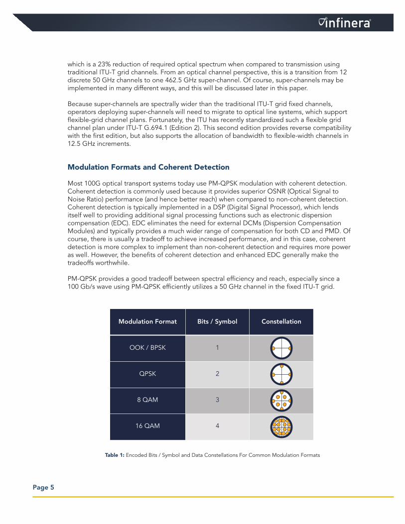
Table 1: Encoded Bits / Symbol and Data Constellations For Common Modulation Formats
However, other modulation formats can be used as well, including lower order modulation (e.g., BPSK, or Binary Phase Shift Keying) or higher order modulation (e.g., 16QAM, or Quadrature Amplitude Modulation). Table 1, previous page, shows the encoded bits per symbol and typical constellation diagrams for four common modulation formats.
For a given data rate, there are performance tradeoffs depending on the modulation format used. Higher order modulation formats, which have reduced spacing between symbol states when compared to lower order formats, are more susceptible to noise and will have a higher BER (Bit Error Rate), all else being equal. Decreased noise immunity translates to reduced transport reach for equivalent BER performance. So while higher order modulation is more spectrally efficient, its reach is shorter. For example, 16QAM with four bits encoded per symbol is spectrally twice as efficient as QPSK with two bits encoded per symbol, but its reach is about a quarter of that of QPSK.
Modern optical transport systems are capable of supporting multiple modulation formats, which can be provisioned per wave in software, and for the first time this allows cable operators to optimize their transport networks for reach versus spectral efficiency, which results in lower CapEx costs. Since the modulation format in these systems is provisionable, this implies variable bandwidth waves, with the final bandwidth determined by the modulation format selected by the operator.
For fixed-channel ITU-T grid plans, where the channel widths and assignments are fixed, this means any improvement in spectral efficiency per wave (assuming the data rate per wave remains constant) does not translate into more capacity per fiber. It does, however, provide backwards compatibility with fixed grid systems, which work efficiently for waves up to 100 Gb/s. Achieving increased fiber capacity with provisionable modulation requires a flex-grid system that supports variable bandwidth channels where bandwidth can be allocated in 12.5 GHz increments per wave and each wave’s center frequency can be assigned as needed.
Terabit Scale Super-Channel Implementation Options
Basically, a super-channel is large unit of optical transport bandwidth that is deployed, turned up, managed, and used as an integral whole. Ideally, a super-channel should be implemented in a single line card, consistent with the definition that a super-channel be managed as a whole, as this provides a significant reduction in fiber connections and significantly simplifies deployment. A super-channel is typically much wider than a traditional ITU-T grid channel to take advantage of the spectrum recovery possible when inter-channel guard bands are eliminated. For increased capacity, multiple super-channels may be deployed on a single fiber.
Within the context of the above definition, however, there are many ways to implement a super-channel. While there is no industry standard for super-channel capacity, most efforts seem to
Page 6

be focused on 400 Gb/s per super-channel or higher, with some cable operators desiring to move immediately to 1 Tb/s or higher. As shown in Figure 3, above, super-channels may be implemented as a single ultra-wide wave, or as two or more waves collected together in a multi-carrier super-channel. The examples below assume a 1.2 Tb/s super-channel with overhead included. Only the transmitter components are considered in Figure 3.
A single-wave super-channel is shown at the left of Figure 3. This approach has the advantage of being simplest to implement since it has the fewest number of components, but has the disadvantage of requiring ultra-fast silicon to support 384 Gbaud. The silicon to support this speed will likely not be available for eight years or so. Moreover, the single-wave super-channel is also quite restrictive in that it allows no flexibility in allocating or routing bandwidth with smaller granularity since it consists of a single indivisible wave.
A dual-wave super-channel is shown at the center of Figure 3. This approach has the advantage of being only moderately more complex to implement when compared to the single-wave version (2x the components), but also has the disadvantage of requiring 192 Gbaud electronics. The silicon required to support this speed will likely not be available for five years or so. The dual-wave super-channel is also restrictive in allocating or routing bandwidth, but it is capable of allowing the two waves to be configured and handled as one integrated channel or two separate channels.
Finally, a 12-wave super-channel consisting of 12 100G waves is shown at the right of Figure 3. This approach requires 12 times the components when compared to the single-wave version, but it operates at speeds that can be supported by today’s silicon technology. This approach also provides maximum flexibility for allocating and routing bandwidth since the individual waves may be combined or not in any permutation, and modulation formats can be assigned on a wave by wave basis. This will be discussed in greater detail below.
The above example of terabit scale super-channel implementation approaches suggests we have a dilemma: either wait several years for high speed silicon to become available so that a single-wave or dual-wave implementation becomes practical, or implement multi-carrier super-channels with 100G waves using extensions of today’s technology. The first approach greatly reduces the super-channel component count and design complexity, but many cable operators cannot wait
Page 7
Figure 3: Super-Channel Implementation Options
1.2 Tb/s PM‐QPSK1 laser4 modulators384 Gbaud electronics
1.2 Tb/s PM‐QPSK2 lasers8 modulators192 Gbaud electronics
1.2 Tb/s PM‐QPSK12 lasers48 modulators32 GBaud electronics
462.5 GHz 462.5 GHz 462.5 GHz
Page 8
several years for this solution because their bandwidth requirements will exceed today’s fiber capacity before this solution becomes available.
On the other hand, a 12-wave multi-carrier super-channel can be developed relatively quickly, but has the disadvantage of requiring a large number of components if implemented using discrete technology. But in its favor, the multi-carrier approach offers a much higher degree of flexibility for bandwidth allocation and routing and in the end can provide greater flexibility for network migration while reducing stranded bandwidth. Multi-carrier terabit scale super-channels are expected to be commercially available within two years and will likely leap-frog 400G super-channels much as 100G waves have done with 40G waves.
Multi-Carrier Super-Channels and Photonic Integration
Fortunately, the dilemma posed above has a technical solution that enables multi-carrier super-channels with 10 or more waves to be built on today’s 100G technology yet with a very low component count. Using photonic integration, it is possible to implement all the optics required for a terabit scale multi-carrier super-channel on a pair of monolithically manufactured Photonic Integrated Circuits (PICs), one each for transmit and receive functions. This brings the overall optical component count back in line with the single-wave implementation and brings the benefits of Moore’s Law to the super-channel domain, and indeed provides a practical path to scaling optical networks in the future.
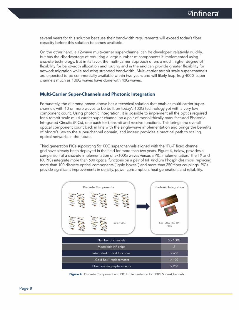
Third generation PICs supporting 5x100G super-channels aligned with the ITU-T fixed channel grid have already been deployed in the field for more than two years. Figure 4, below, provides a comparison of a discrete implementation of 5x100G waves versus a PIC implementation. The TX and RX PICs integrate more than 600 optical functions on a pair of InP (Indium Phosphide) chips, replacing more than 100 discrete optical components (“gold boxes”) and more than 250 fiber couplings. PICs provide significant improvements in density, power consumption, heat generation, and reliability.
Figure 4: Discrete Component and PIC Implementation for 500G Super-Channels
Discrete Components Photonic Integration
50 x 100G 5 x 100G TX / RXPICs
Number of channels
Monolithic InP chips
Integrated optical functions
“Gold Box” replacements
Fiber coupling replacements
5 x 100G
2
> 600
> 100
> 250

Page 9
Multi-Carrier Terabit Super-Channels
One likely super-channel implementation configuration is a 1.2 Tb/s multi-carrier super-channel based upon 12x100G waves and implemented as two PICs (TX and RX). This configuration is particularly desirable because it will allow, for example, three 400G Ethernet clients to be transported very efficiently in a single super-channel. Using 12 waves that may be individually tuned to any particular frequency in the flexible grid spectrum and that may also be individually programmed for modulation format, a flexible transport system is possible that can support the ITU-T fixed grid and flexible grid, as well as allow network optimization based upon balancing reach versus spectral capacity. Figure 5, below, shows some of the channel and tuning combinations that can be provisioned for the 12 waves supported on the PIC. Of course, any combination of tuning and channel assignments as well as modulation formats supported can simultaneously be provisioned up to the full 1.2 Tb/s of capacity of the PIC.
The left diagram in Figure 5 shows all 12 waves combined into a single 1.2 Tb/s super-channel. This super-channel may be tuned as needed anywhere in the ITU-T flexible grid. This is the most spectrally efficient configuration since it allows the closest spacing of all the individual waves, and in this case, all the capacity of the super-channel must originate and terminate at the same two endpoints.
The center diagram in Figure 5 shows the 12 waves combined into three independently tunable 400 Gb/s super-channels. This configuration will be particularly useful in supporting the emerging 400G Ethernet client interfaces, and allows the bandwidth in each 400G super-channel to be routed and add/dropped independently. This configuration is slightly less spectrally efficient than the 12-carrier super-channel previously discussed.
Finally, the diagram at the right of Figure 5 shows the 12 waves configured completely independently. This is the least spectrally efficient configuration because each wave must now have guard bands on either side, but it has the additional benefit of allowing full compatibility with the 50 GHz fixed-channel ITU-T grid.
Figure 5: 1.2 Tb/s PIC-Based Super-Channel Configuration Options
462.5GHz 162.5GHz 162.5GHz 162.5GHz 50GHz 50 GHz
1.2T PM‐QPSK 400G PM‐QPSK 400G PM‐QPSK 400G PM‐QPSK 100G PM‐QPSK 100G PM‐QPSK
12 X
1.2 Tb/sSuper‐Channel
3 x 400 Gb/sSuper‐Channels
12 x 100 Gb/sIndividual Channels

Page 10
The previous example showed various channel and wave combinations for PM-QPSK, but multiple modulation formats can be supported as well, and these can be individually provisioned on a per wave or per channel basis. Table 2, above, shows the spectral requirements, C-band capacity, and representative optical reach for various modulation formats and super-channel configurations for the same 12-wave 1.2 Tb/s PIC. Of course, reach is dependent upon many factors, including fiber type, FEC (Forward Error Correction), span spacing, and other factors.
Multi-carrier, flexible grid super-channel technology offers the fastest technology path to increasing fiber capacity. Compared to individual 100G waves transporting 9.6 Tb/s on a fiber pair, 1.2 Tb/s super-channels are capable of delivering 12 Tb/s while using the same optical modulation format, an increase of 25%.
Compared to a single wavelength, high data rate transponder, a multi-carrier super-channel offers dramatically more efficient and flexible bandwidth allocation across the network. Moreover, when implemented using VLSI (Very Large Scale Integration) PICs, these super-channels are no more complex or costly than single wavelength solutions.
Flexible Grid ROADM Architectures
Flexible Grid
As mentioned previously, traditional WDM networks rely on the fixed ITU-T grid and the spacing defined therein, but the coarse granularity of this grid leads to poor spectrum utilization. To alleviate the waste of spectrum due to guard bands in the fixed grid channel plan and to support high capacity super-channels to meet evolving bandwidth demands, ITU-T has defined a flexible grid in the latest WDM grid specification, G.694.1. The new flexible grid defines WDM channels having a frequency slot width granularity of 12.5 GHz with 6.25GHz central frequency granularity in contrast to the coarser 50 GHz width in the fixed grid. The flexible grid gives the ability
Modulation
PM-QPSK
PM-8QAM
PM-16QAM
1.2 Tb/sSuper‐Channel
400 Gb/sSuper‐Channel
100 Gb/sWave
462.5 GHz / Channel12 Tb/s C-Band
4000 km
162.5 GHz / Channel11.6 Tb/s C-Band
4000 km
50 GHz / Channel9.6 Tb/s C-Band
4000 km
312.5 GHz / Channel18 Tb/s C-Band
1800 km
112.5 GHz / Channel16.8 Tb/s C-Band
1800 km
37.5 GHz / Channel12.8 Tb/s C-Band
1800 km
237.5 GHz / Channel24 Tb/s C-Band
900 km
87.5 GHz / Channel21.6 Tb/s C-Band
900 km
37.5 GHz / Channel12.8 Tb/s C-Band
(900 km, so use 8QAM)
Table 2: 1.2 Tb/s PIC: Spectral Requirements per Channel, C-Band Capacity, and Optical Reach
Note: Figures are for a 4.8THz extended C-Band, 0.22dB/km fiber loss, and full OSNR margin.

Page 11
to define an aggregate super-channel spectral width of N × 12.5 GHz to accommodate any combination of optical carriers, modulation formats, and data rates. This supports provisionable modulation formats, which allow operators to balance their requirements for increased spectral efficiency versus extended reach of the optical signals. In addition, the flexible grid provides the capability to elastically allocate frequency slots on demand and/or modify the modulation format of optical channels according to traffic demands. This allows resources to be used efficiently in response to traffic variations. Figure 6, above, shows an example of a flexible grid spectrum allocated to 400G and 1Tb super-channels along with today’s 50 GHz 100G channels.
The main motivation for deploying flexible grid technology is to make the network future-proof by creating an optical line system that can be used for future transmission formats that may require more than 50 GHz channel spacing. Over the past two decades the bit rates and modulation formats of optical transmission systems have evolved dramatically, from 2.5 Gb/s OOK to 100 Gb/s PM-QPSK. As this progression to increased bit-rate per channel has continued, it has become increasingly difficult to increase the bit rate while maintaining spectral efficiency and reach. To space 100 Gb/s channels 50GHz apart has required the adoption of dual-polarization QPSK transmission. But to support even higher data rate super-channels, which will require spectrum to be allocated in multiples of 12.5GHz depending upon the reach and capacity requirement for that link, a flexible grid line system is ideal, and will allow operators to install line systems today that will be able to accommodate virtually any type of super-channel tomorrow.
Multi-Layer Switching
While advances in optical transport technologies enable network capacity to scale to multi-Tb/s per fiber pair, network planners need to consider not just fiber capacity, but also what mix of service types are expected to traverse the transport network. While the line side transmission rate is evolving beyond 100 Gb/s, more than 95% of the client services in the network are still 10G or less, and muxponders are typically used to aggregate these services in a point-point fashion onto 100G wavelengths.
Under these circumstances, however, many studies have shown that photonic-only switching can be inefficient, as ROADMs utilized with 100G muxponders do not provide any ability to groom or switch sub-wavelength traffic within or between wavelengths. This can lead to low utilization of deployed bandwidth and therefore over-deployment of 100G wavelengths, also termed the “muxponder tax”[2]. In addition, as network traffic volumes increase and more and more
200 GHz1Tb Super-Channel
384 Slices of 12.5GHz in 4.8THz Extended C Band
150 GHz400G Super-Channel
50 GHz100G
Channel
50 GHz100G
Channel
Figure 6: ITU-T G.694.1 Flexible Grid Architecture
wavelengths are used, it becomes increasingly difficult to find unused end-end wavelengths across the network. This creates what is called “wavelength blocking,” which can require the use of incremental and otherwise unnecessary re-gens for wavelength conversion and static grooming to eliminate the problem[3].
To alleviate this problem, the next generation optical network should support a multi-layer switching architecture in which the network nodes integrate both digital OTN switching with ODU0 granularity and super-channel based reconfigurable optical switching. This architecture combines the benefits of a digital switching architecture for sub-wavelength grooming (which greatly reduces stranded line side capacity) and super-channel optical switching for operational simplicity and a greater degree of flexibility for express traffic.
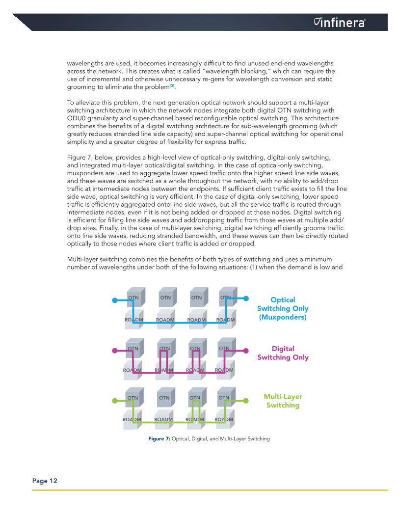
Figure 7, below, provides a high-level view of optical-only switching, digital-only switching, and integrated multi-layer optical/digital switching. In the case of optical-only switching, muxponders are used to aggregate lower speed traffic onto the higher speed line side waves, and these waves are switched as a whole throughout the network, with no ability to add/drop traffic at intermediate nodes between the endpoints. If sufficient client traffic exists to fill the line side wave, optical switching is very efficient. In the case of digital-only switching, lower speed traffic is efficiently aggregated onto line side waves, but all the service traffic is routed through intermediate nodes, even if it is not being added or dropped at those nodes. Digital switching is efficient for filling line side waves and add/dropping traffic from those waves at multiple add/drop sites. Finally, in the case of multi-layer switching, digital switching efficiently grooms traffic onto line side waves, reducing stranded bandwidth, and these waves can then be directly routed optically to those nodes where client traffic is added or dropped.
Multi-layer switching combines the benefits of both types of switching and uses a minimum number of wavelengths under both of the following situations: (1) when the demand is low and
Page 12
Figure 7: Optical, Digital, and Multi-Layer Switching
OTN
ROADM
OTN
ROADM
OTN
ROADM
OTN
ROADM
OTN
ROADM
OTN
ROADM
OTN
ROADM
OTN
ROADM
OTN
ROADM
OTN
ROADM
OTN
ROADM
OTN
ROADM
OpticalSwitching Only(Muxponders)
Digital Switching Only
Multi-LayerSwitching
Page 13
the wavelengths are not filled, and (2) when demand is high and the wavelengths can be highly filled. Multi-layer switching uses digital grooming for improved filling of individual wavelengths, while for fully-filled wavelengths, optical switching is used to express these waves through the intermediate nodes without the need for OEO (Optical-Electrical-Optical) conversions or digital switching for grooming purposes. Moreover, the multi-layer switching architecture provides the highest degree of flexibility as the network evolves and service demands change. Network studies using real-life network models have shown that such multi-layer switching can reduce the total number of WDM ports by 13-22% compared to all-optical or all-digital switching alone[4].
As optical transport evolves from single-carrier 100G waves to multi-carrier super-channels, digital grooming of every super-channel at every node may not be necessary, or desired. Firstly, once digital grooming has fully filled a super-channel, it is most cost-effective for that channel to optically express through intermediate add/drop nodes, and terminate only at its end destination. In this context, optical ROADMs enable whole super-channels to be easily switched and reconfigured in order to maximize operational flexibility, while integrated digital switching maximizes bandwidth utilization and CapEx efficiency on individual super-channels.
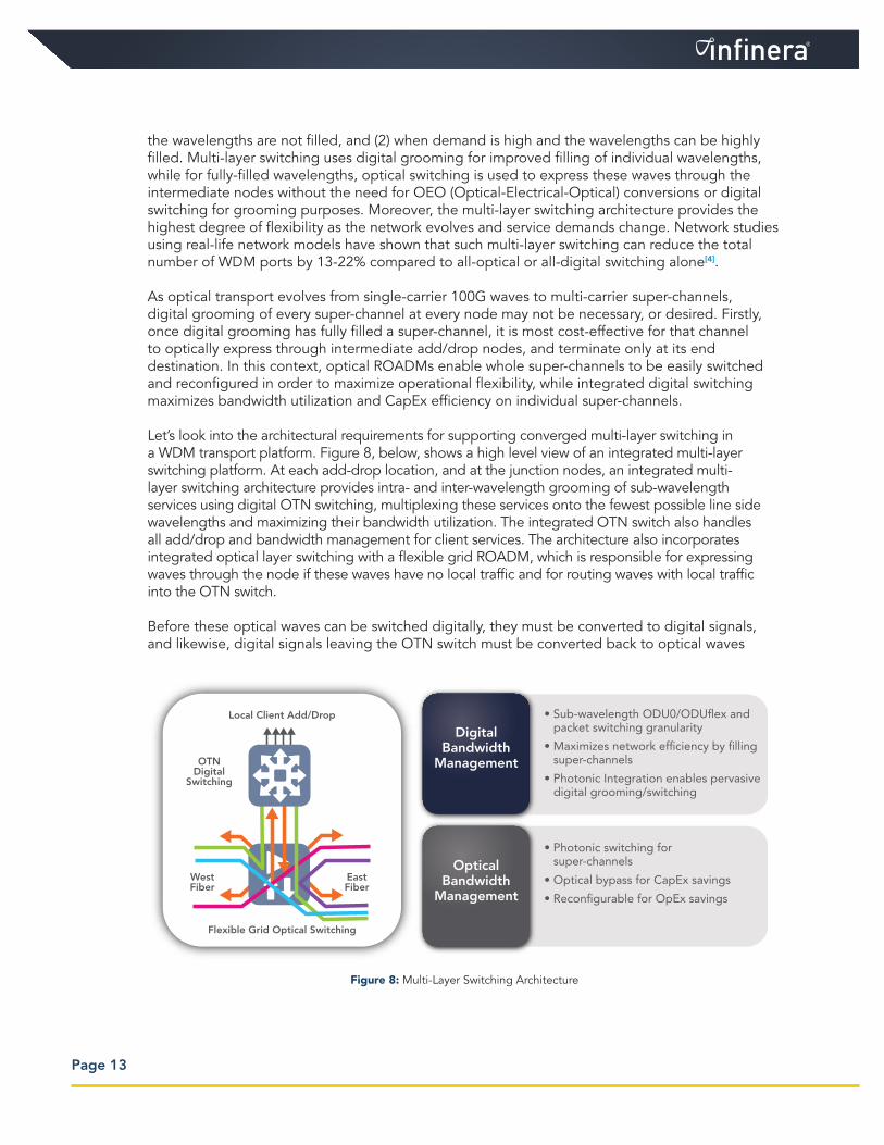
Let’s look into the architectural requirements for supporting converged multi-layer switching in a WDM transport platform. Figure 8, below, shows a high level view of an integrated multi-layer switching platform. At each add-drop location, and at the junction nodes, an integrated multi-layer switching architecture provides intra- and inter-wavelength grooming of sub-wavelength services using digital OTN switching, multiplexing these services onto the fewest possible line side wavelengths and maximizing their bandwidth utilization. The integrated OTN switch also handles all add/drop and bandwidth management for client services. The architecture also incorporates integrated optical layer switching with a flexible grid ROADM, which is responsible for expressing waves through the node if these waves have no local traffic and for routing waves with local traffic into the OTN switch.
Before these optical waves can be switched digitally, they must be converted to digital signals, and likewise, digital signals leaving the OTN switch must be converted back to optical waves
Figure 8: Multi-Layer Switching Architecture
Local Client Add/Drop
Flexible Grid Optical Switching
OTNDigital
Switching
WestFiber
EastFiber
• Sub-wavelength ODU0/ODU�ex and packet switching granularity
• Maximizes network ef�ciency by �lling super-channels
• Photonic Integration enables pervasive digital grooming/switching
• Photonic switching for super-channels
• Optical bypass for CapEx savings
• Recon�gurable for OpEx savings
DigitalBandwidth
Management
OpticalBandwidth
Management
Page 14
for transport. While it is possible to implement an integrated WDM/switch architecture using conventional optical components, which typically require one package per optical function, wide-spread adoption has been limited by the compromises in cost, power consumption, system size and reliability that happen when discrete components are used to provide digital termination of wavelengths at an OTN switch. The development and wide-spread deployment of multi-channel PIC technology has helped address these issues[5].
Since the WDM and OTN functionality is converged into a single platform, this results in reduced space, power, and complexity when compared to using stand-alone OTN switch and WDM transport platforms.
Flexible Grid ROADM
Transparent optical switching elements, in which signals are routed optically without conversion to electrical signals, are attractive to optical network operators due to the savings in equipment and consumed power, but also due to their bit rate and modulation format independence. Of the multitude of optical switching elements proposed over the years, wavelength selective switches (WSS) have proven to meet the broadest range of optical networking requirements and at a reasonable price.
These switches accept WDM traffic on their input port and can independently route individual waves to any of the output ports. The WSS functionality is used to architect ROADMs, the most common node structure of mesh networks. Traditional ROADMs are designed for the fixed grid channel plan. However, with the introduction of multi-carrier super-channels, the super-channel and its constituent sub carriers need to be provisioned, transported and switched across the network as a single entity, and hence require the ROADM to support variable bandwidth switching in multiples of 12.5GHz for super-channels of any width.
The transmission characteristics of a flexible grid ROADM require the multi-carrier super-channel to be treated homogeneously as a single entity, i.e., a group of adjacent multi-carrier channels sent to same port must form a combined passband without any gaps or amplitude dips. The primary difference between the flexible and the fixed grid ROADM is that the flexible grid ROADM supports full flexibility in bandwidth allocation and switching (within the 12.5 GHz granularity requirement), whereas the fixed grid ROADM is constrained to switching fixed bandwidth channels (typically 50 GHz). The ability to resize and groom channels is more crucial in a flexible grid network than in a fixed-grid network because the evolution of traffic demands can create stranded bandwidth slices that are too narrow to support later-arriving demands.

Page 15
Figure 9, above, shows the evolution of ROADMs from fixed to flexible grid. The key enabler of switching super-channels based on the flexible grid is LCoS (Liquid Crystal on Silicon), a cutting-edge switch technology used to produce the industry’s most feature-rich and cost-effective WSS modules. Compared to other switching technologies, such as MEMS (Micro-Electro-Mechanical Systems), the WSS platform with LCoS is highly customizable via software, allowing for true “on the fly” reconfigurability of channel bandwidth, channel location, and channel routing.
Migration to Flexible Grid
For greenfield applications, depending on the operator’s requirements, it makes sense to install a flexible grid architecture throughout the network. While a flexible grid network provides several benefits, it is unlikely in brownfield applications that the entire network needs to be upgraded to flexible grid on day one. Starting from a network with enough capacity for growth, the most likely scenario is that some links in the network will grow more quickly than others and become congested, acting as bottlenecks to future network growth. It is in these links where flexible grid will likely be first deployed to extend network capacity, and thereby delay the need for lighting up a second fiber pair.
A migration strategy is thus required so that new technology can be introduced where it has the most benefit, but without having to start with a new network build. Unfortunately, such a migration has been infeasible in the past, mainly due to the lack of interoperability between old and new line systems. There are, however, some synergies between the fixed flexible grids, mostly due to the capabilities of flexible grid WSSs. Fortunately, flexible grid ROADMS are capable of supporting fixed grid channels simultaneously with flexible grid channels, which can allow existing fixed grid waves to co-reside on a flexible grid line system with multi-carrier super-channels.
While a full description of all the steps necessary to engineer and migrate a line system from fixed to flexible grid is beyond the scope of this paper, the migration process will primarily
Figure 9: Evolution of ROADM with Flexible Grid
50GhzWSS WSS
50Ghz
50Ghz
Nx12.5Ghz
Nx12.5Ghz
Nx12.5Ghz
Fixed Grid Bandwidth Management Flexible Grid Bandwidth Management
Page 16
require traffic to be temporarily migrated off the span to be upgraded and the new flexible grid line system components to be installed. The original fixed grid traffic may then be moved back onto the original span, and any new super-channels may then be turned up. It may be necessary or desirable as the original fixed grid channels are being moved back to their original span to allocate these to new channels in the grid to maximize available bandwidth for super-channels and to minimize any engineering constraints for optical layer performance.
Summary and Conclusions
The unceasing demand for additional optical transport bandwidth is driving new technology at a very rapid pace to increase spectral efficiency and bandwidth utilization, all while lowering the overall transport cost per bit. Multi-carrier super-channels (which operate on a flexible grid channel plan that supports variable bandwidth channels) increase spectral capacity by eliminating the inefficient guard bands associated with fixed grid channel plans and by enabling provisionable modulation formats, which allow operators to configure their networks for optimum spectral capacity versus reach. 16QAM modulation can deliver up to 24 Tb/s of capacity per fiber, but at the expense of much shorter reach compared to QPSK.
Ideally, multi-carrier super-channels will support independent tuning of each wave in the super-channel, which will allow super-channel carriers to be configured as independent waves, using independent modulation techniques, or in combinations that support one or more super-channels of varying size, up to the full bandwidth of the super-channel. One likely configuration for future super-channels is a 12x100G multi-carrier channel, which will transport three 400G Ethernet services in a 1.2 Tb/s super-channel, configured either as one 1.2 Tb/s channel or as three 400 Gb/s channels. Multi-carrier super-channels offer the promise of significantly increasing transport capacity per fiber while providing greatly enhanced flexibility, both of which result in increased network efficiency.
To support multi-carrier super-channels, a flexible grid line system is required, which allows channel and switching bandwidth to be assigned as needed to each individual variable bandwidth super-channel. The flexible grid architecture supports bandwidth assignments in the C-band in 12.5 GHz increments, allowing efficient use of the C-band for both fixed and flexible grid channels.
To achieve maximum transport efficiency with super-channels, which have much higher bandwidth than 100G fixed grid waves, a multi-layer switching architecture with integrated optical and digital layer switching is required. This architecture optimizes super-channel bandwidth utilization by allowing sub-lambda OTN digital grooming within and between super-channels, and optimizes super-channel routing between destinations with flexible grid optical
Page 17
switching. The resulting “optical data plane” is also ideally suited to integrated Control Plane operation, whether that is GMPLS today, or a Carrier SDN Control Plane in the future.
With optical super-channels, flexible grid ROADMs and line systems, and integrated multi-layer optical/digital switching, all driven and coordinated by a unified Control Plane, operators will have a flexible set of tools for optical transport to ensure capacity demands can be met and at the lowest possible cost.
This paper was originally authored for and presented at SCTE Cable-Tec Expo ‘14, held in Denver, Colorado September 22-25, 2014.
Bibliography
[1] Hart, Gaylord. “Evolving Optical Transport Networks to 100G Lambdas and Beyond.” NCTA 2011 Cable Connection Spring Technical Forum Conference Proceedings. Session 27, Chicago, IL, June 15, 2011.
[2] Bertolini, M. et al. “Benefits of OTN Switching Introduction in 100Gbit/s Optical Transport Networks.” Proc. 2012 Optical Fiber Communications conference/National Fiber Optic Engineers Conference, Session NM2F, Los Angeles, CA, March 4-8, 2012.
[3] Melle, S. and V. Vusirikala. “Network Planning and Architecture Analysis of Wavelength Blocking in Optical and Digital ROADM Networks.” Proc. 2007 Optical Fiber Communications conference/National Fiber Optic Engineers Conference, Session NTuC, Anaheim, CA, March 25-29, 2007.
[4] Roy, S. et al. “Evaluating Efficiency of Multi-Layer Switching in Future Optical Transport Networks.” Proc. 2013 Optical Fiber Communications conference/National Fiber Optic Engineers Conference, Anaheim, CA, March17-21, 2013.
[5] Kish, F. et al. “Current Status of Large-Scale InP Photonic Integrated Circuits.” IEEE J. Sel. Top. Quantum Elect., Vol. 17, No. 6, Nov.-Dec. 2011.

Page 18
Abbreviations & Acronyms
Acronym Description
BER Bit Error RateBPSK Binary Phase Shift KeyingCapEx Capital ExpenditureCD Chromatic DispersionDCM Dispersion Compensation ModuleDSP Digital Signal ProcessorDWDM Dense Wave Division MultiplexingEDC Electronic Dispersion CompensationFEC Forward Error CorrectionInP Indium PhosphideITU International Telecommunication Unionλ Lambda, or one optical waveLCoS Liquid Crystal on SiliconMEMS Micro-Electrical-Mechanical SystemsODU0 OTN Optical channel Data Unit 0 (~1.25 Gb/s)OEO Optical-Electrical-OpticalOOK On-Off KeyingOpEx Operational ExpenditureOSNR Optical Signal to Noise RatioOTN Optical Transport NetworkPIC Photonic Integrated CircuitPMD Polarization Mode DispersionPM-QPSK Polarization Multiplexed QPSKQAM Quadrature Amplitude ModulationQPSK Quadrature Phase Shift KeyingROADM Reconfigurable Optical Add/Drop MultiplexerRX ReceiveTX TransmitWSS Wavelength Selective Switch

Infinera Corporation140 Caspian CourtSunnyvale, CA 94089 USATelephone: +1 408 572 5200Fax: +1 408 572 5454www.infinera.com
Have a question about Infinera’s products or services?Please contact us via the email addresses below.
Americas: [email protected] & Pacific Rim: [email protected], Middle East, and Africa: [email protected] E-Mail: [email protected]
www.infinera.com
Specifications subject to change without notice.
Document Number: WP-NGON-10-2014
Infinera® Corporation reserves the right to make changes without further notice to any products or data herein to improve reliability, function, or design.
Information furnished by Infinera Corporation is believed to be accurate and reliable. However, Infinera Corporation does not assume any liability arising out of the application or use of this information, nor the application or use of any product or circuit described herein, neither does it convey any license under its patent rights nor the rights of others.
© 2014 by INFINERA CORPORATION. All rights reserved. Infinera, Infinera DTN™, IQ™, Bandwidth Virtualization™, Digital Virtual Concatenation™, Infinera Digital Optical Network™, and Intelligent Transport Network are trademarks of Infinera Corporation in the U.S. and other countries.
Other names and brands may be claimed as the property of others