
The Engineering, Installation, Integration and Operation ... Woodward 505 Inlet Steam Pressure 30.66...
9
Proc S Afr Sug Technol Ass (2002) 76 365 THE ENGINEERING, INSTALLATION, INTEGRATION AND OPERATION OF A 20 MW CO-GENERATING TURBINE ALTERNATOR AT HIPPO VALLEY ESTATES S NDORO 1 , J GROENEWALD 2 and G WENHAM 2 1 Hippo Valley Estates, P O Box 1 Chiredzi, Zimbabwe 2 PGBI International, P O Box 2668 Rivonia, 2128, South Africa E-mail: [email protected] Abstract The installed backpressure power generation capacity at Hippo Valley Estates (HVE) comprised a number of old and small sets, which had become inadequate to reliably supply the total power requirements of the mill and estate. A new 20 MW backpressure turbine alternator (TA) was installed to satisfy the full factory demand on its own and export a surplus to the national grid. The project was completed in fifteen months and the TA was synchronised during the crushing season as planned. This article describes the benefits, identifies the issues and shares some of the lessons learned in engineering, installing and operating the largest unit of its kind in Africa. Keywords: Turbine, Alternator, Generation, Steam Introduction and rationale The power generation plant at HVE comprised an assortment of old and small, backpressure, pass- out and condensing TAs whose ages ranged from 23 to 50 years, as listed in Table 1. Table 1. HVE installed power generation plant. Unit Type Make Date of installation Installed capacity (MW) Available capacity* (MW) No 1 Back pressure English Electric 1964 3.5 3.0 No 2 Pass-out/condensing English Electric 1964 5.0 (3/2) 5.0 (3/2) No 3 Condensing Met Vick 1950 7.5 3.5 No 4 Condensing Met Vick 1950 2.0 0 No 5 Back-pressure WH Allen 1977 8.0 7.0 Total condensing (MW) 11.5 5.5 Total back pressure (MW) 14.5 13.0 * These ratings are at HVE’s high-pressure steam ranges and backpressure steam conditions. In most cases, the specific steam consumptions for these machines are significantly higher than their original ratings, largely due to turbine blade degradation. HVE’s installed backpressure capacity was 32 kW/tch, which was low compared to the South African Sugar Industry’s average of 62 kW/tch (see Figure 1) and Triangle’s 75 kW/tch (which includes an irrigation load of 8-10 MW). This disparity and the poor condition and old age of the equipment, prompted HVE to motivate the installation of new generating capacity some time ago. It was only recently, in light of power rationing and the frequent and prolonged power cuts, that the installation of new reliable capacity became imperative to secure operations and cash flow.
Transcript of The Engineering, Installation, Integration and Operation ... Woodward 505 Inlet Steam Pressure 30.66...

Proc S Afr Sug Technol Ass (2002) 76 365
THE ENGINEERING, INSTALLATION, INTEGRATION AND OPERATION OF A 20 MW CO-GENERATING TURBINE
ALTERNATOR AT HIPPO VALLEY ESTATES
S NDORO1, J GROENEWALD2 and G WENHAM2
1Hippo Valley Estates, P O Box 1 Chiredzi, Zimbabwe
2PGBI International, P O Box 2668 Rivonia, 2128, South Africa E-mail: [email protected]
Abstract The installed backpressure power generation capacity at Hippo Valley Estates (HVE) comprised a number of old and small sets, which had become inadequate to reliably supply the total power requirements of the mill and estate. A new 20 MW backpressure turbine alternator (TA) was installed to satisfy the full factory demand on its own and export a surplus to the national grid. The project was completed in fifteen months and the TA was synchronised during the crushing season as planned. This article describes the benefits, identifies the issues and shares some of the lessons learned in engineering, installing and operating the largest unit of its kind in Africa. Keywords: Turbine, Alternator, Generation, Steam
Introduction and rationale The power generation plant at HVE comprised an assortment of old and small, backpressure, pass-out and condensing TAs whose ages ranged from 23 to 50 years, as listed in Table 1.
Table 1. HVE installed power generation plant.
Unit Type Make Date of installation
Installed capacity (MW)
Available capacity*
(MW) No 1 Back pressure English Electric 1964 3.5 3.0 No 2 Pass-out/condensing English Electric 1964 5.0 (3/2) 5.0 (3/2) No 3 Condensing Met Vick 1950 7.5 3.5 No 4 Condensing Met Vick 1950 2.0 0 No 5 Back-pressure WH Allen 1977 8.0 7.0
Total condensing (MW) 11.5 5.5 Total back pressure (MW) 14.5 13.0
* These ratings are at HVE’s high-pressure steam ranges and backpressure steam conditions. In most cases, the
specific steam consumptions for these machines are significantly higher than their original ratings, largely due to turbine blade degradation.
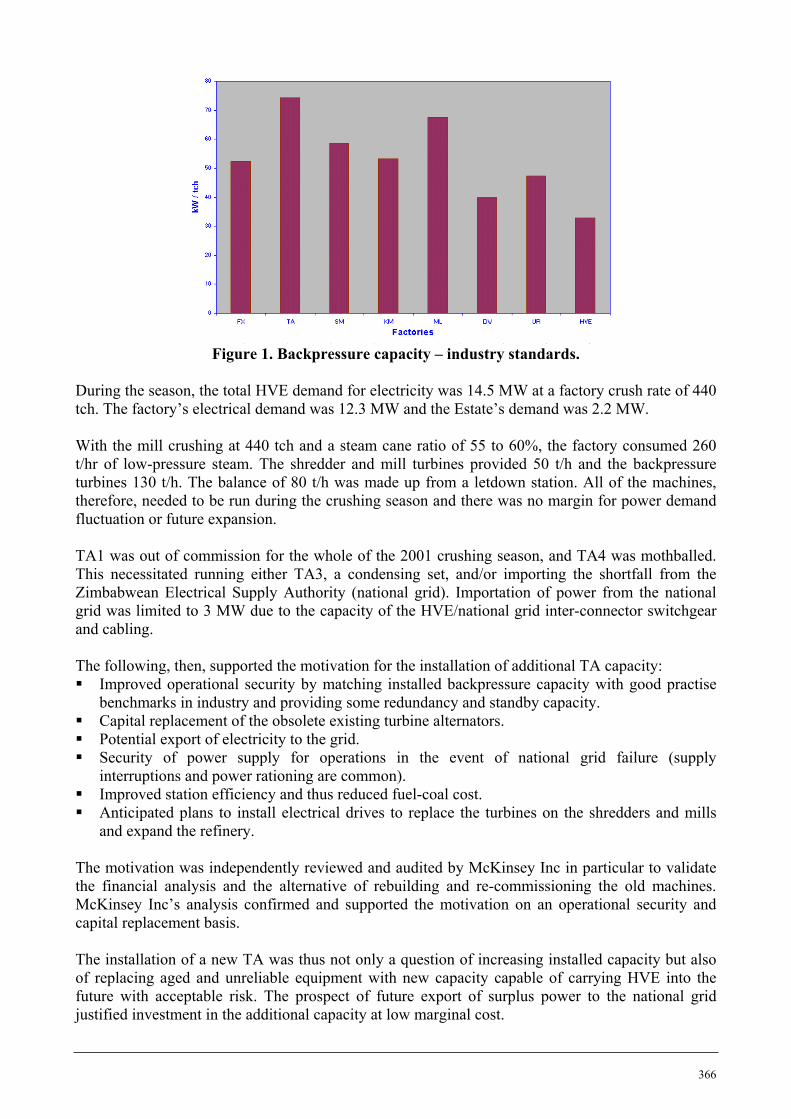
HVE’s installed backpressure capacity was 32 kW/tch, which was low compared to the South African Sugar Industry’s average of 62 kW/tch (see Figure 1) and Triangle’s 75 kW/tch (which includes an irrigation load of 8-10 MW). This disparity and the poor condition and old age of the equipment, prompted HVE to motivate the installation of new generating capacity some time ago. It was only recently, in light of power rationing and the frequent and prolonged power cuts, that the installation of new reliable capacity became imperative to secure operations and cash flow.
366
Figure 1. Backpressure capacity – industry standards.
During the season, the total HVE demand for electricity was 14.5 MW at a factory crush rate of 440 tch. The factory’s electrical demand was 12.3 MW and the Estate’s demand was 2.2 MW. With the mill crushing at 440 tch and a steam cane ratio of 55 to 60%, the factory consumed 260 t/hr of low-pressure steam. The shredder and mill turbines provided 50 t/h and the backpressure turbines 130 t/h. The balance of 80 t/h was made up from a letdown station. All of the machines, therefore, needed to be run during the crushing season and there was no margin for power demand fluctuation or future expansion. TA1 was out of commission for the whole of the 2001 crushing season, and TA4 was mothballed. This necessitated running either TA3, a condensing set, and/or importing the shortfall from the Zimbabwean Electrical Supply Authority (national grid). Importation of power from the national grid was limited to 3 MW due to the capacity of the HVE/national grid inter-connector switchgear and cabling. The following, then, supported the motivation for the installation of additional TA capacity: Improved operational security by matching installed backpressure capacity with good practise
benchmarks in industry and providing some redundancy and standby capacity. Capital replacement of the obsolete existing turbine alternators. Potential export of electricity to the grid. Security of power supply for operations in the event of national grid failure (supply
interruptions and power rationing are common). Improved station efficiency and thus reduced fuel-coal cost. Anticipated plans to install electrical drives to replace the turbines on the shredders and mills
and expand the refinery. The motivation was independently reviewed and audited by McKinsey Inc in particular to validate the financial analysis and the alternative of rebuilding and re-commissioning the old machines. McKinsey Inc’s analysis confirmed and supported the motivation on an operational security and capital replacement basis. The installation of a new TA was thus not only a question of increasing installed capacity but also of replacing aged and unreliable equipment with new capacity capable of carrying HVE into the future with acceptable risk. The prospect of future export of surplus power to the national grid justified investment in the additional capacity at low marginal cost.
367
Plant sizing and risk management schedule A 15 MW unit is adequate to provide the security necessary for power supply to the mill for cane throughputs up to 500 tch. The procurement process, however, revealed that a 20 MW set would cost only 15% more than a 15 MW unit. This prompted the thought that the surplus 5 MW could readily be sold into the national grid until such time as the crushing capacity of the mill was increased to 600 tch. A study of the technical and operational implications of designing and running such a large machine at varying loads and turndowns was necessary. Risk analyses, due diligences and quality assurance programmes were implemented to ensure that the larger unit would be responsive to HVE’s requirements once that step change design risk was acceptable. Approval to proceed with Phase 1 was given in April 2000. The approval covered the supply and installation of a new 20 MW backpressure Turbine Alternator. A second Phase would entail upgrading the existing HVE/national grid inter-connector switchgear and cabling together with the necessary protection equipment, to allow co-generation and bi-directional power flow. A contract extension for the specification and design through to commissioning and hand-over for Phase 1 on a turnkey basis was awarded to Project Management Services/PGBI Engineers and Constructors International (PGBI). A budget was approved and a completion date of the 7 July 2001 was set.
Technical details Peter Brotherhood Ltd (PBL) of the UK was selected as the TA supplier. They offered an Alstom alternator. Specification The unit’s performance characteristics are outlined below:
Turbine PBL Frame 1 – skid mounted, impulse design Power 20 MW Governor Woodward 505 Inlet Steam Pressure 30.66 bar absolute Inlet Steam Temperature 400 0C Exhaust Steam Pressure 2.22 bar absolute Speed 6000 rpm Gearbox David Brown double helical,
parallel shaft, with integrated electrically driven barring gear
Power Rating 20 MW Reduction Ratio 4 : 1 AGMA Service Factor 1.5 Alternator Alstom - Salient pole rotor – Brush-less excitation Power 25 MVA @ 0.8 pf Voltage 11 kV Frequency 50 Hz Speed 1500 rpm

368
Features Permanently fitted vibration monitoring sensors (Bentley Nevada) Top-mounted double bank alternator air coolers each rated for 80% of max load Gland steam condenser Backup cooling water provided by existing TA CW pumps Voltage control by automatic voltage regulator (AVR Basler) Alternator rated at 25 MVA fitted with diode protection Steam end pedestal supported on a ‘panting plate’ design MMI colour screen/keypad. Initiates automatic start-up with ramp up rates through critical
speed range (4000 RPM) Steam separator in the HP steam line – Kelburn
The frame size offered by PBL was for a 25 MW turbine with modified steam conditions. The number of stages is dependent on the steam inlet and outlet conditions, and at HVE, 6 stages were required. Each stage/disc is sized to suit the blade requirements and its specific steam conditions. The PBL rotor design has its blade attachment discs integral with its forged shaft. The blades are machined from solid material (instead of casting) and dovetailed for installation into the discs with an outer ring attached to the blades of the HP stages. This configuration offers a more conservative design in respect of the rotor integrity, is less prone to disc cracking, is only one harmonic frequency lower than the operating frequency and, as a result, has a longer life expectancy. The journal bearing arrangement is standard for a Frame 1 - the turbine designed to suit the increased thrust. Operational performance The machine’s operational performance parameters needed to accommodate a wide range of operating conditions. In particular, variations in efficiency and exhaust steam temperatures at low power outputs (high turn down ratios) had to be minimised. Figure 2 shows the combined efficiency of the turbine and alternator for various power outputs and the relatively flat efficiency and steam consumption curves.
0
5
10
15
20
25
0 2 4 6 8 10 12 14 16 18 20Electrical Power Output (MW)
Spec
ific
Stea
m C
onsu
mpt
ion
(t/M
Wh)
0%
10%
20%
30%
40%
50%
60%
70%
80%
90%
100%Ef
ficie
ncy
Fact
or
Specific Steam Consumption
Efficiency
Figure 2. Specific steam consumption and TA unit efficiency versus power output.
369
Technical Risk Management PBL’s previous largest similar installation was a 12 MW unit, which was installed at St Aubin Mill in Mauritius in 1997. The turbine design for HVE was a first-of-a-kind for PBL. This turbine design was a step increase (66%) from PBL’s previous experience. This necessitated implementing a programme of Technical Risk Management to address the risks associated with the step change. The issues managed, included:
The standard HP steam inlet system and casing had to accommodate the increased flow Rotor design increased from 15 MW to 20 MW design Critical speed of rotor is lower than operating speed (as was the Frame 1) Journal and thrust bearings had to be designed for the higher load ‘Black-out’ oil supply Labyrinth seals are required to accommodate a substantially larger shaft and expansions Potentially unacceptably higher exhaust steam casing velocities Emergency stop valve loads and forces at higher flow Foundation vibration tolerances Optimising blade design for varying turn-down ratios
A consolidated listing of areas of concern was identified and a formal risk management program was developed and applied. The program included:
Visits to similar units for operational experience Independent design reviews of the new PBL design HAZOP studies Manufacturing tests and inspections Training and involvement of all operating staff
Some of the more important issues resulting are shown below:
Steam inlet capacities and their resultant forces on the emergency stop valves and casing The turbine rotor design to handle the higher steam mass flow rates and critical speed
evaluations The design of the journal and thrust bearings to handle the larger loads and their associated
lubrication requirements The ability of the couplings between the turbine, gearbox and alternator to transmit the
higher torque The effect of varying turn down requirement and the effect on efficiency Control, protection and governing for co-generation operations Management of critical speed transition Black-start and lubrication implications Operating in the event of losing the large TA System stability – one large machine and five small ones Control of exhaust steam temperature at low load
Operational philosophy
Certain unique design measures had to be adopted to satisfy HVE’s operational requirements of reliable electrical power, maintaining low-pressure steam volumes and temperatures, while exporting surplus power to the national grid. Specifically, the installation had to be capable of operating in the following modes:
Island mode Load sharing mode Co-generation and export power mode
370
Island mode In this mode the mill would rely totally on the new 20 MW set for its power requirements. In the event of the TA tripping, no power would be available to operate the Auxiliary Oil Pump (AOP) and normally the turbine would run down without lubrication to the bearings. To prevent this, an overhead, run down oil tank was fitted. Its height, capacity and reticulation were designed so that it only feeds when the main pump pressure falls below the required threshold during run down. Re-starting (black start) requires national grid power to be physically reconnected to supply the power station’s boards to restart the TA auxiliaries. To maintain the process steam supply, one small boiler would have to be brought back on range, using coal. The TA could then be back in full service in 10 to 15 minutes. When operating in Island mode, a speed or frequency set point (i.e 50 Hz) is maintained by the governor. Load sharing mode A trip in island mode of operation would stop milling operations. The new TA, therefore, had to be capable of running in parallel with the existing TAs in load sharing mode. In order to ensure proper and proportional load sharing between the TAs, all governor droop settings needed to be the same (4%). The new TA’s electronic governor is programmable to match the mechanical droop setting on the other sets. If the 20 MW TA tripped out, the other set(s) would have to increase the load from an idle or low load condition to make up the deficit. Since the next biggest machine is only 7 MW, a load shedding facility had to be installed to sequentially isolate non-strategic areas of the mill until the demand is matched. Co-generation and export power mode While co-generating, the electronic governor can control the TA to maintain pre-set backpressure (backpressure mode) or power (power limiting mode) settings. In backpressure mode, the new TA’s load fluctuates as demand for LP steam changes in the factory. A ‘uni-directional Real Power Sensor’ is fitted to the alternator circuit breaker to measure the actual power and provides a feedback signal to the governor. This arrangement also protects the alternator from overloading. In power limiting mode, a fixed amount of power will be exported to the national grid with the let down station supplying any deficit. When connected to the national grid, the machine is controlled against an exhaust backpressure set point (backpressure control) as the grid is already at 50 Hz. In this case a bi-directional real power sensor monitors and measures the power imported or exported from/to the national grid and sets the governor to limit the power to the national grid. In HVE’s case the export power limit is set to 4 MW. A fixed flow rate set point for the let down station replaces its normal method of controlling the pressure in the exhaust steam range. Exhaust steam pressure is now controlled by the TA, which also limits the inefficient expansion of high-pressure steam.

371
The grid absorbs the variation in power output in this mode at a frequency of 50 Hz. In either backpressure or power limiting modes, a fault on the national grid will trip the breaker. The electronic governor is set to automatically revert to speed/frequency control and reset the let down station to control the exhaust steam range pressure.
Electrical protection Apart from the normal protection switchgear, which mill power stations employ to protect their alternators, three other principal hazards must be guarded against whilst co-generating, the possibility of:
The Power Station being ‘pulled into the grid’ if a fault occurs in the grid, which causes excessive power demand from HVE. This hazard is addressed by a bi-directional real power sensor on the national grid breaker, which feeds back to the governor and limits export power to a pre-determined set point, as well as the over current relays which are part of the production design.
The national utility closing the inter-connector without synchronization. (Unsynchronized connection between the Utility and mill power is prevented by a ‘synch check relay’.)
Losing synchronisation as a result of auto re-closing by the national utility to clear line faults. The auto re-closer locks open and can only be reconnected by adopting an agreed procedure. This hazard is currently being addressed jointly by HVE and the utility by the careful allocation of responsibilities between the parties during switching and reconnection processes. A document, ‘Joint Systems Operating Manual’ is currently being developed to formalise and entrench the procedure.
Current and future operating regimes
HVE is currently running its plant in load sharing mode as arrangements for co-generation are yet to be implemented by the utility. The planned installation includes inter-connector switchgear; protection equipment and cabling rated to handle the export power envisaged. A step up transformer has been installed within HVE’s premises to increase the voltage from the 11 kV used within the factory to 33 kV required for the national grid. Commissioning of this installation is expected in May 2002.
Installing and commissioning during milling operations The contract schedule required the project to be completed four months into the milling season. Consequently, all tie-ins for utilities and services and preparation for electrical connections had to be completed in the previous off-crop to allow seamless integration and commissioning of the new TA. Two separate units, comprising the integral turbine, gearbox and oil tank (37 tons) and the alternator (48 tons), were shipped to Durban and transported to site by road. Despite delivery delays, caused by flood damage to two bridges during Cyclone Eline, which required a detour, pre-clearance expedited the importation through the Beitbridge border post recovering the lost time and beating the original delivery schedule by 4 days.
372
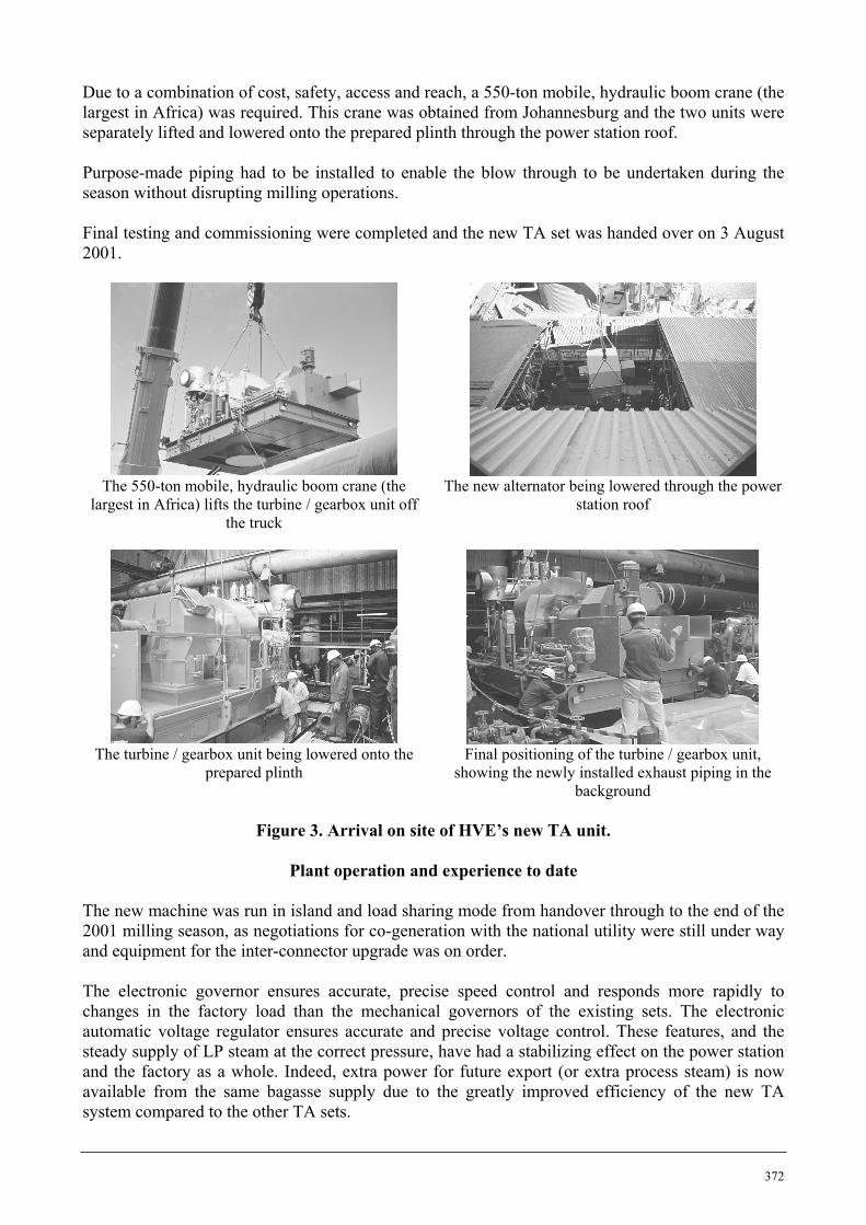
Due to a combination of cost, safety, access and reach, a 550-ton mobile, hydraulic boom crane (the largest in Africa) was required. This crane was obtained from Johannesburg and the two units were separately lifted and lowered onto the prepared plinth through the power station roof. Purpose-made piping had to be installed to enable the blow through to be undertaken during the season without disrupting milling operations. Final testing and commissioning were completed and the new TA set was handed over on 3 August 2001.
The 550-ton mobile, hydraulic boom crane (the
largest in Africa) lifts the turbine / gearbox unit off the truck
The new alternator being lowered through the power station roof
The turbine / gearbox unit being lowered onto the
prepared plinth Final positioning of the turbine / gearbox unit,
showing the newly installed exhaust piping in the background
Figure 3. Arrival on site of HVE’s new TA unit.
Plant operation and experience to date
The new machine was run in island and load sharing mode from handover through to the end of the 2001 milling season, as negotiations for co-generation with the national utility were still under way and equipment for the inter-connector upgrade was on order. The electronic governor ensures accurate, precise speed control and responds more rapidly to changes in the factory load than the mechanical governors of the existing sets. The electronic automatic voltage regulator ensures accurate and precise voltage control. These features, and the steady supply of LP steam at the correct pressure, have had a stabilizing effect on the power station and the factory as a whole. Indeed, extra power for future export (or extra process steam) is now available from the same bagasse supply due to the greatly improved efficiency of the new TA system compared to the other TA sets.

373
Performance tests were conducted shortly after handover and revealed that the turbine performance exceeded the initially stated parameters up to 14.5 MW load. As the tie-ins and upgrading of the HVE/national grid inter-connector are yet to be implemented, the machine cannot be run at its full rated capacity of 20 MW. However, current performance measurements indicate that the MCR specifications will be achieved. The machine successfully ran through to the end of the 2001 season without problem, except for a minor oil leak on the exhaust end bearing labyrinth seal.
Establishing a co-generation agreement with the national Utility
As with all utility co-generation projects, the enabling policy and agreements are fundamental to achieving success. Issues such as power quality, reliability and price require much effort to resolve and define to the parties’ mutual satisfaction. The fundamental situation remains that the sugar mill is, in essence, a competitor and obtaining and establishing practical and commercially attractive arrangements with its client, who is also a competitor, is difficult. There have been recent international initiatives to encourage power generated from clean, sustainable and renewable energy sources. The application of carbon credits and other financial incentives are gaining momentum. Utilities are, therefore, under pressure to offer attractive terms to co-generators and Independent Power Producers complying with these requirements, even when their supply is intermittent.
Conclusions The installation of large TA units in traditional sugar mill power stations, to benefit from the economies of scale and export of power, have been shown to be technically and economically feasible. Design and operational risks have, thus far, been shown to be manageable and acceptable by applying good engineering and operational management principles and experience. The statutory and regulatory issues involved in acquiring utility acceptance for co-generation are not to be under estimated.
Acknowledgements Peter Brotherhood Limited, UK for its responsiveness to design requirements and its co-operation under difficult environmental circumstances. HVE staff for the clear specification of the operational requirements and practices. PGBI Engineers and Constructors (Pty) Ltd for the overall project management, concept and engineering design, construction and integration. The Technical Management Department (TMD) of Tongaat-Hulett for its technical review of the turbine and alternator. Bosch & Associates, for its contribution to the electrical and protection integration design. All intellectual property rights with regard to the 20 MW turbine alternator discussed in this paper shall remain vested in Peter Brotherhood limited.


![]970022]9] IVleridional Velocity, Absolute Mach Number, and Absolute and Relative Flow Angle, 50% Span 77 39 Circumferential Distributions of Rotor Inlet Total Pressure, Absolute Velocity,](https://static.fdocuments.in/doc/165x107/5b2a36d67f8b9ad8298ba504/9700229-ivleridional-velocity-absolute-mach-number-and-absolute-and-relative.jpg)
