The Eight Steps to Specify a Catalyst Bed - AIChE
37
The Eight Steps to Specify a Catalyst Bed Gary Gildert for the East Tennessee Local Section of the AIChE November 4, 2014
Transcript of The Eight Steps to Specify a Catalyst Bed - AIChE

The Eight Steps to Specify a Catalyst Bed
Gary Gildert for the East Tennessee Local Section of the AIChE
November 4, 2014

2
* Before amortisation of acquired intangibles, major impairment and restructuring charges and profit or loss on disposal of businesses
and, where relevant , related tax effects.
Johnson Matthey Overview
• A speciality chemicals company and a world leader in sustainable
technologies
• Origins date back to 1817, floated 1942, FTSE 100 company since
June 2002
• £11.2 billion revenue and underlying profit before tax* of £427.3
million for year ended 31st March 2014
• Operations in over 30 countries with around 12,000 employees
• Leading global market positions in all its major businesses

Our Strategy
3
Technology leadership
forms the basis of
Johnson Matthey’s
strategy to deliver
superior long term
growth
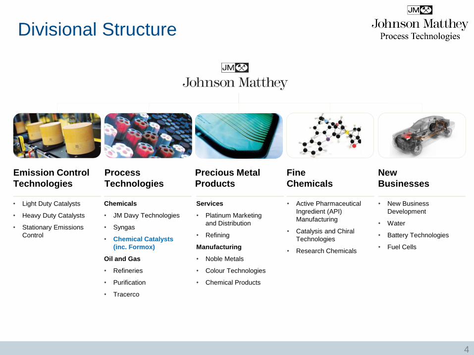
Divisional Structure
4
Emission Control
Technologies
Process
Technologies
Precious Metal
Products
Fine
Chemicals
New
Businesses
Chemicals
• JM Davy Technologies
• Syngas
• Chemical Catalysts
(inc. Formox)
Oil and Gas
• Refineries
• Purification
• Tracerco
Services
• Platinum Marketing
and Distribution
• Refining
Manufacturing
• Noble Metals
• Colour Technologies
• Chemical Products
• Active Pharmaceutical
Ingredient (API)
Manufacturing
• Catalysis and Chiral
Technologies
• Research Chemicals
• New Business
Development
• Water
• Battery Technologies
• Fuel Cells
• Light Duty Catalysts
• Heavy Duty Catalysts
• Stationary Emissions
Control

Process Technologies
Chemicals Oil & Gas
A global supplier of catalysts, licensing technologies and other services to the
petrochemical, syngas, oil refining and gas processing industries.
5

Chemical Catalysts
6
• Fixed bed supported catalysts in base metals (e.g. Ni, Cu, Co, Zn) from Oberhausen,
Emmerich (Germany) and Clitheroe (UK)
• Ni catalysts for edible oils & oleochemicals from Emmerich (Germany) and Taloja
(India)
• Sponge Metal™ catalysts from Tennessee (USA)
• Supported precious metal catalysts from Royston (UK) and West Deptford (USA)
Overview, Markets and Segments
Petrochemicals
Olefins
Alcohols
Solvents and Fuels
Fluorochemicals
Chemical Intermediates
Environmental
Oleochemicals
Fatty Acids
Edible Oils
Polyols
Natural Detergent Alcohols
Biorenewables
Formaldehyde
FORMOX™ Fe/Mo catalysts
FORMOX™ Plant Technology
Custom Catalysts

Gary Gildert
Internationally recognized expert in hydro treating with 24 patents and over 40 publications
• Bachelor of Applied Science (Ch.E.), University of Waterloo 1981
• Masters of Business Administration, Rice University in 2005
• Registered professional engineer in Ontario, Canada (1986) and Alberta, Canada (1990)
• Member of American Institute of Chemical Engineering since 1997, STS Chair 2013
• Member of American Chemical Society and South West Catalysis Society since 2005
Over 30 years of petrochemical knowledge including new process development and catalyst design and manufacture
• 11 years operations support and process design with Petrosar
• 8 years Process Development Manager Hydrogenation Technology at Chemical Research and Licensing (CDTECH) in Houston, TX.
• 6 years, Regional Sales Manager, Americas for catalysts including technical support globally for olefins purification catalysts
• Co-founder Custom Catalytic Solutions, responsible for marketing, sales, technical service, and finance.
• 5 years, Senior Principal Process Engineer, Johnson Matthey, Process Technologies with responsibilities for technical service, technical mentoring and marketing new hydrogenation catalysts.
7

The Eight Steps
Process
Configuration
Catalyst
Selection Performance
Specification
Mass
Balance
Catalyst
Volume
Cycle Length
Life
Heat
Balance
Reactor
Diameter
© G. Gildert 2006 - 2014
8

1. Performance Specification
• Feed rate + margin
Maximum rate for sizing
Normal rate for life
• Stream properties
Hydraulics
Detailed composition, or
Actual density, viscosity (gas and
liquid if 2-phase) , surface tension
• Key concentrations for bed
sizing – feed and product.
Limiting reactant
Basis for specification
• Hydrogen source Purity
Pressure
• Poisons assumptions vs. history
• Alternate cases One case governs sizing
Others do not affect result
• Units of measurement
9

Company: Date:
Location: By:
Process Information
De-ethanizer Overheads Normal Maximum Feed Contaminants
Feed rate kg/hr H2S ppm m
Composition COS ppm m
Methane mol % Arsine ppb w
Acetylene mol % water ppm m
Ethylene mol %
Ethane mol %
Propylene + mol %
Hydrogen Composition
Hydrogen mol %
Methane mol %
Carbon Monoxide mol %
Ethane + mol %
Product Specification Maximum Typical
Acetylene ppm m
Hydrogen ppm m
Application InformationAcetylene Converter, Tail-end
Application Questionnaire
10

2. Process Configuration
• Batch Reactor
• Continuous Stirred Tank Reactor
• Plug Flow Reactor
Adiabatic
Isothermal
• Fluidized Bed
11

• Discovery of most reaction chemistry
(Chemists)
• Reusable powdered catalyst
• Easily reproduced
• Easy translation to (small) commercial scale
Configuration - Batch
12
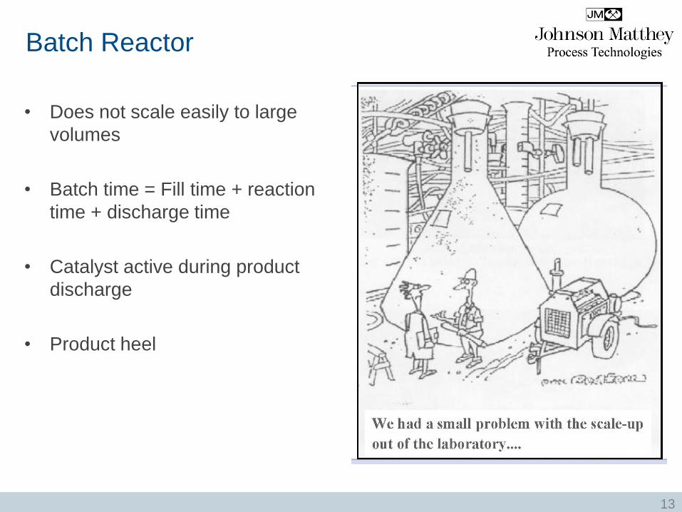
• Does not scale easily to large
volumes
• Batch time = Fill time + reaction
time + discharge time
• Catalyst active during product
discharge
• Product heel
Batch Reactor
13
We're still working out the bugs in our scale-up process
© Jerry King, chemcialprocessing.com/cartoon-caption
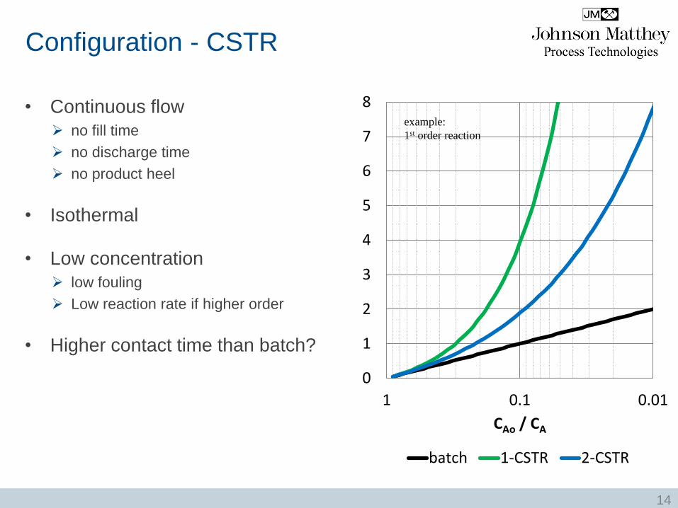
• Continuous flow
no fill time
no discharge time
no product heel
• Isothermal
• Low concentration
low fouling
Low reaction rate if higher order
• Higher contact time than batch?
0
1
2
3
4
5
6
7
8
0.010.11
CAo / CA
batch 1-CSTR 2-CSTR
example:
1st order reaction
Configuration - CSTR
14

TRACERCO DiagnosticsTM
Residence Time of Stirred Tank Reactor
Outlet Inlet
Time (s)
Ra
dia
tio
n In
ten
sit
y
STE value = 1.25
Inlet Detector
Injection
Outlet Detector
15

Configuration - PFR
• Most Common Configuration
• Vapor Phase, Liquid Phase, Trickle Bed
• Many variations
16

Two Reactor Designs
Radial Flow
Catalyst Beds
Feed
Product
Axial Flow (most common)
Sector Cylinders
Center Pipe
Product
Feed
17
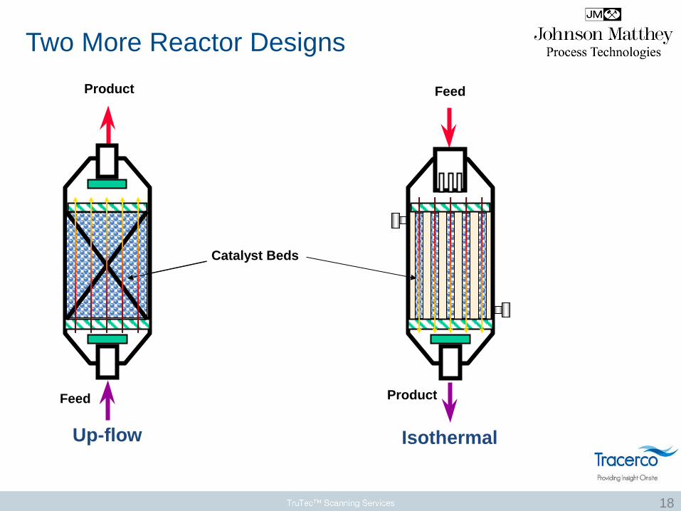
Two More Reactor Designs
Product
Feed
Up-flow
Catalyst Beds
Feed
Product
Isothermal
18

Single Bed Reactor with Spare
Feed
Hydrogen
Feed
Feed – Effluent
Exchanger
Main
Reactor
Product
Feed
Heater
Spare
Reactor Effluent
Cooler
19

2 X 2 (Two in series with two spares)
Feed
Hydrogen
Feed
Feed – Effluent
Exchanger
Main
Reactor
Product
Feed
Heater
Spare
Reactor Effluent
Cooler
Inter-
cooler
20

2 + 1 (a.k.a. Merry-Go-Round, two in series with one spare)
Feed
Hydrogen
Feed
Feed – Effluent
Exchanger
Lead
Reactor
Product
Feed
Heater
Clean-up
Reactor
Effluent
Cooler
Spare
Reactor
Inter-
cooler
21
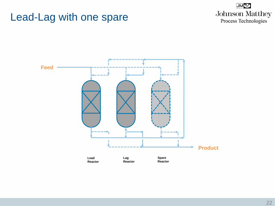
Lead-Lag with one spare
Feed
Lead
Reactor
Product
Lag
Reactor
Spare
Reactor
22

Recycle Reactor
Liquid Feed
Hydrogen
Feed
Feed
Drum
Hydrogenation
Reactor
Flash
Drum
Product
Vent
1
pf
pi
if CC
CC
CC
f
r
23

3. Catalyst Selection
1. Active metal
i.e. hydrogenations: Pd, Pt, Ni, Cu, Co, Fe
2. Promoter
Depends on the required effect: Ag, Au, Mo, W, Pb, Sn
3. Carrier (Support)
Alumina, Silica, Zeolite, Carbon
4. Shape
sphere, extrusion, tablet
5. Size
1 mm to 6 mm
• Standardized product by application
24

Catalyst Development
• In-house state of the art testing facilities
• Gas and liquid phase testing capabilities
specifically designed for different
olefin streams
• Test work uses synthetic feed blends to
mimic industrial compositions
• Dedicated development team
researching full and selective
hydrogenation catalysts for
various markets
• Proving on catalyst offerings
under customer feed blends and
process conditions
25

Catalysts for specific services
http://www.jmprotech.com/literature-downloads
26

Pyrolysis Gasoline
Market leading products to : -
• Improve induction period and colour
• Reduce gum content of gasoline blending components
• Reduce fouling in the downstream hydrodesulphurisation unit
Nickel catalysts
• sulphur and heavy metal tolerance
• preservation of aromatics
Palladium catalysts
• simple activation
• high olefin selectivity
Available in four different types to suit different activation situations
27

The Eight Steps
28
Process
Configuration
Catalyst
Selection Performance
Specification
Mass
Balance
Catalyst
Volume
Cycle Length
Life
Heat
Balance
Reactor
Diameter
© G. Gildert 2006 - 2014

4. Material Balance
• Ch.E. 101
• Moles!
• Conversion for spec component
• Account for every reaction
• Amount of “reactant” (hydrogen, oxygen, fuel)
i.e. H2:Ac, scfh per bbl
Excess reactant
% conversion
• Equilibrium limits
• Recycle composition
• Vent
• Spreadsheet
• Process simulation
29

5. Heat Balance
• Required temperature
Minimum inlet
WABT
EIT
• Heat of Reaction
Heat of formation
Heat of combustion
• Pressure Effects
Dew point
Bubble point
V / L split
• VLE Data
• Spreadsheet?
• Process simulation
30

Heat and Material Balance Issues
• Poor performance if temperature rise is greater than 75˚F (42˚C) per bed Activity & selectivity issues
Increase recycle
Add another bed in series
• Must be at least 15°C (25°F) above the dew point to prevent condensation on catalyst Feed superheat
Intercooler operation
• Hydrogen solubility issues Choose thermo package carefully
2-phase feed more complicated than single phase
• Vaporization due to heat of reaction Channeling
Hot spots
31

The Eight Steps
32
Process
Configuration
Catalyst
Selection Performance
Specification
Mass
Balance
Catalyst
Volume
Cycle Length
Life
Heat
Balance
Reactor
Diameter
© G. Gildert 2006 - 2014
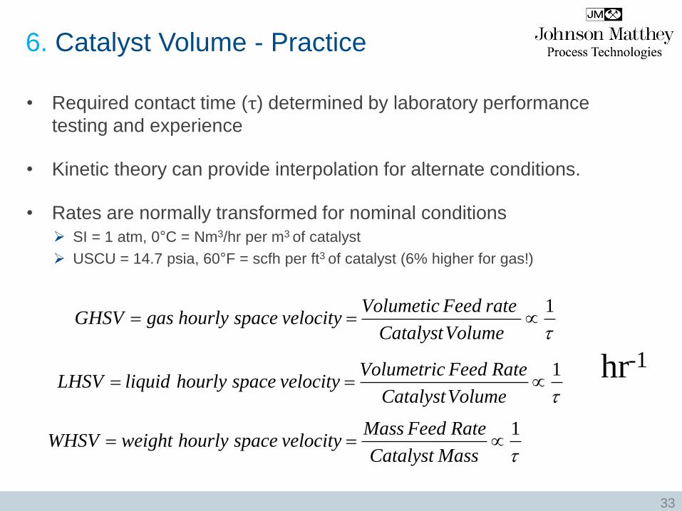
6. Catalyst Volume - Practice
• Required contact time (τ) determined by laboratory performance
testing and experience
• Kinetic theory can provide interpolation for alternate conditions.
• Rates are normally transformed for nominal conditions
SI = 1 atm, 0°C = Nm3/hr per m3 of catalyst
USCU = 14.7 psia, 60°F = scfh per ft3 of catalyst (6% higher for gas!)
1
VolumeCatalyst
rateFeedVolumeticvelocityspacehourlygasGHSV
1
VolumeCatalyst
RateFeedVolumetricvelocityspacehourlyliquidLHSV
hr-1
1
MassCatalyst
RateFeedMassvelocityspacehourlyweightWHSV
33
7. Reactor Diameter
• L/D = ½ to 5 Radial distribution of short beds
Wall effects on tall beds
• Bed Height Limits Maximum based on catalyst crush strength, loading, channeling
Minimum based on history, conversion
• Superficial Velocity Maximize for mass transfer
Limited by channeling for 2-phase systems
Turbulence via Re
Mass Transfer via Sh
• Pressure Drop / Flow Regime Process design to minimize
High cost & system limits
2-phase flow regime for improved mass transfer = reaction rate
34
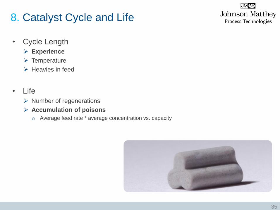
8. Catalyst Cycle and Life
• Cycle Length
Experience
Temperature
Heavies in feed
• Life
Number of regenerations
Accumulation of poisons
o Average feed rate * average concentration vs. capacity
35

The Eight Steps
36
Process
Configuration
Catalyst
Selection Performance
Specification
Mass
Balance
Catalyst
Volume
Cycle Length
Life
Heat
Balance
Reactor
Diameter
© G. Gildert 2006 - 2014