THE EFFECTS ON CRUISE DRAG OF INSTALLING LONG-DUCT REFAN ... · PDF filema —7 3 26023...
36
M7 3 26023 A — NASA CR-121218 REPORT MDC J5947 THE EFFECTS ON CRUISE DRAG OF INSTALLING LONG-DUCT REFAN-ENGINE NACELLES ON THE MCDONNELL DOUGLAS DC-8-50 AND -61 C ASE by J. T. CALLAGHAN, J. E. DONELSON AND J. P. MORELLI prepared for NATIONAL AERONAUTICS AND SPACE ADMINISTRATION NASA Lewis Research Center Contract NAS 3-16814 oou /WTCOO/V/VJEt-JL DOUGLAS, ^ https://ntrs.nasa.gov/search.jsp?R=19730017296 2018-05-01T04:48:58+00:00Z
Transcript of THE EFFECTS ON CRUISE DRAG OF INSTALLING LONG-DUCT REFAN ... · PDF filema —7 3 26023...

M 7 3 2 6 0 2 3A —
NASA CR-121218REPORT MDC J5947
THE EFFECTS ON CRUISE DRAG OF INSTALLING
LONG-DUCT REFAN-ENGINE NACELLES ON THEMCDONNELL DOUGLAS DC-8-50 AND -61
CASE
by J. T. CALLAGHAN, J. E. DONELSON AND J. P. MORELLI
prepared forNATIONAL AERONAUTICS AND SPACE ADMINISTRATION
NASA Lewis Research CenterContract NAS 3-16814
oou
/WTCOO/V/VJEt-JL DOUGLAS,
https://ntrs.nasa.gov/search.jsp?R=19730017296 2018-05-01T04:48:58+00:00Z

1. Report No.
NASA CR-1212184. Title and Subtitle
The Effects on Cruise DragRefan-Engine Nacelles on tDC-8-50 and -61
2. Government Accession No.
of Installing Long-Ducthe McDonnell -Douglas
7. Author(s)
J. T. Callaghan, J. E. Donelson, and 0. P. Morel li
9. Performing Organization Name and Address
Douglas Aircraft CompanyLong Beach, California
12. Sponsoring Agency Name and Address
National Aeronautics and Space AdministrationWashington, D. C. 20546
3. Recipient's Catalog No.
5. Report Date
May 19736. Performing Organization Code
8. Performing Organization Report No.
MDC J594710. Work Unit No.
11. Contract or Grant No.
NAS 3-1681413. Type of Report and Period Covered
Contractor Report14. Sponsoring Agency Code
15. Supplementary Notes
Project Manager, Arthur MedierosResearch Center, Cleveland, Ohio
NASA/Lewis
16. Abstract
A high-speed wind tunnel test was conducted in the NASA Ames 11-foot facility inJanuary 1973 to determine the effect on cruise performance of installing long-duct refan-engine nacelles on the DC-8-50 and -61 models. Drag data and wing/pylon/nacelle channel pressure data are presented. At a typical cruise conditionthere exists a very small interference drag penalty of less than one-percent oftotal cruise data for the Refan installation. Pressure data indicates that somesupersonic flow is present in the inboard channel of the inboard refan nacelleinstallation, but it not sufficient to cause any wave drag on boundary layerseparation. One pylon modification, which takes the form of pylon bumps, wastested. It resulted in a drag penalty, because its design goal of eliminatingshock-related interference drag was not required and the bump thus became asource of additional parasite drag.
1 7. Key Words (Suggested by Author(s) )
DC-8refanned long duct nacellehigh speedpylon modifications
19. Security Classif: (of this report)
Unclassified
18. Distribution Statement
20. Security Classif. (of this page) 21 . No. of Pages 22. Price*
Unclassified 38: For sale by the National Technical Information Service, Springfield, Virginia 22151
NASA-C-168 (Rev. 6-71)

MDC J5947
THE EFFECTS ON CRUISE DRAG OF
INSTALLING LONG-DUCT REFAN-ENGINE NACELLES
ON THE MCDONNELL-DOUGLAS DC-8-50 AND -61
by J. T. Callaghan, J. E. Donelson, and J. P. Morelli
MCDONNELL DOUGLAS CORPORATION
prepared for
NATIONAL AERONAUTICS AND SPACE ADMINISTRATION
NASA Lewis Research Center
Contract NAS 3-16814

FOREWORD
The high-speed wind tunnel test described in this report was performed by the
Douglas Aircraft Company, Configuration Design Branch - Aerodynamics of the
McDonnell Douglas Corporation. The work,sponsored by NASA Lewis and reported
herein,was performed between January and April 1973.
This report has been reviewed and is approved by:
< "O*A -, _.(_ \J — -—i-yw^ ^, .
J. E. Donelson Date S "14"NASA Refan Project Aerodynamicist
F. T. Lynch,'Chief DateConfiguration Design BranchAerodynamics
f\^m Tfr" t jTf~-~—~- ^—» ._ -75
R. B. Harris ' Date g -//' (3Chief AerodynamicsEngineer for Design
0. RT-franfi DateDirector of Aerodynamics

TABLE OF CONTENTS
1.0 SUMMARY 1
2.0 INTRODUCTION 3
3.0 SYMBOLS 5
4.0 APPARATUS AND TEST 74.1 Model Description 7
4.1.1 Basic Model 74.1.2 Nacelle Geometry 74.1.3 Nacelle Installation Comparison 34.1.4 Pylon Modifications g
4.2 Test Apparatus g4.2.1 Facility and Model Installation g4.2.2 Instrumentation g
4.3 Test Procedure and Data Accuracy g
5.0 RESULTS AND DISCUSSION 115.1 Basic Refan Installation 115.2 Pylon Modification 12
6.0 CONCLUSIONS 13
7.0 REFERENCES 15
8.0 FIGURES 17

1.0 SUMMARY
A high-speed wind tunnel test was conducted in the NASA Ames 11-foot facility
in support of the NASA refan program in order to assess the effect on cruise
performance of installing long-duct refan-engine nacelles on the DC-8-50 and
-61 models, which currently have short-duct nacelle installations. This test
was prompted by the desire to determine the feasibility of using a common
long-duct refan-engine nacelle for all DC-8 models. Since the existing long-
duct nacelles on the DC-8-62 and -63 models are farther forward of the wing
leading edge than the short-duct nacelles, the refan installation was not
considered to be a problem on those aircraft. The long-duct refan nacelle
installed, in the existing aft short-duct position of the Series 50 and 61,
however, represented a potential interference drag problem due to the position
of the nacelle relative to the wing. The purpose of this test was, therefore,
to determine if an interference drag penalty existed for the installation of
the long-duct refan nacelle on the existing Series 50 and 61 short-duct pylon,
and, if necessary, to investigate potential fixes designed to minimize or
eliminate the interference penalty. The potential fixes took the form of
pylon bumps, which were designed to improve the area distribution in the
channel formed by the wing, pylon, and nacelle.
Analysis of the results from this test leads to the following conclusions:
1. At a typical cruise condition there exists an interference drag
penalty of less than one-percent of total cruise drag for the
installation of the long-duct refan nacelle on the existing (minimum
structural change) Series 50 and 61 short-duct pylon. This very
small penalty would, however, be much more than off-set by the large
improvement, demonstrated on the existing DC-8, of a long-duct
nacelle over a short-duct nacelle.
2. At cruise conditions some supersonic flow is present in the inboard
channel of the inboard refan-nacelle installation, but it is not
sufficient to cause any wave drag or boundary layer separation. The
small interference drag penalty results from a general thickening in
the boundary layer of some of the components when they are integrated.

3. The one pylon modification tested resulted in a drag penalty, because
its design goal of eliminating shock-related interference drag was
not required and the bump thus became a source of additional parasite
drag.
4. From aircraft performance considerations, a common long-duct refan-
engine nacelle is certainly feasible for all DC-8 models.

2.0 INTRODUCTION
To determine the feasibility of a common long-duct refan-engine nacelle for
all DC-8 models, serious consideration must be given to the aerodynamic design
of the pylons for minimum interference drag. Previous wind tunnel and flight
experience (e.g. Reference 1) has shown that the cruise drag is extremely
sensitive to the placement of the nacelles and pylons on the wing. The
potential interference penalties that can occur are related to the local Mach..
numbers in the channel formed by the wing, pylon, and nacelle and are mani-
fested as a wave drag associated with shocks in the channel and/or as a drag
associated with a thickening and possible separation of the boundary layer on
the nacelle, pylon, or wing. The existing long-duct nacelle installation on
the DC-8-62 and -63 and the short-duct nacelle installation on the Series 50
and 61 models are essentially interference-drag free installations. Since the
long-duct nacelles on the Series 62 and 63 models are farther forward of the
wing leading edge than the short-duct nacelles, the refan installation is not
considered to be a problem on those aircraft. The long-duct refan nacelle
installation on the Series 50 and 61 models, however, poses a potential problem.
If the refan-engine were installed on the Series 50 and 61 as it is on the
Series 62 and 63 (nacelle well out in front of the wing), reskinning of the
wing would be required for flutter considerations. If, on the other hand, the
long-duct refan nacelle were installed in the existing aft short-duct position,
a significant interference drag might result. The reason for this concern can
be seen from the sketch below, which presents a comparison of the wing-pylon-
nacelle channel area distributions for the refan installation with those for
min
INBOARD
Severe InterferenceDrag Penalty OUTER BOUNDARY
OF CHANNEL
DC-8 Refan.
Interference FreeInstallation
PYLON STATION

an interference-drag free installation and an installation with a significant
interference penalty. The latter two area distributions are for similar
installations that were previously tested. The area distribution for the
installation with an interference penalty corresponds closely to the development
of supersonic flow and shocks measured in the channel. It can be seen from
the sketch that the convergence - divergence of the refan area distribution is
worse than that of the interference-free installation.
As a result of this concern a high-speed wind tunnel test was conducted in the
NASA Ames 11-foot transonic wind tunnel in January 1973 (Ames Test No. 11-703).
The purpose of this test was to determine if an interference drag penalty
existed for the long-duct refan nacelle installation on the existing Series 50
and 61 short-duct pylon, and, if necessary, to investigate potential fixes
designed to minimize or eliminate the interference penalty. The potential
fixes took the form of pylon bumps, which were designed to improve the channel
area distribution shown in the sketch above. Three sets of modified pylons
were designed and fabricated for this test. A sketch of the effect these
pylons will have on the channel area distribution is presented below.
min
Aft Bump
Fwd Bump
Fwd & Aft Bump
Basic Refan Pylon
PYLON STATION
The pertinent results from this test are analyzed and discussed in this report.

A .min
3.0 SYMBOLS
Ratio of local channel cross-section area to minimum value
C Drag coefficient, D/q S
ACn Incremental drag coefficient
CT Lift coefficient, L/q SL o w
C Pressure coefficient,(P - P )/qp o o
M Mach number
p Static pressure, psf
q Dynamic pressure, psf
S Wing reference area, sq ftw
n Ratio of local semi-span station to total semi-span
SUBSCRIPTS
L Local conditions
o Free stream conditions

4.0 APPARATUS AND TEST
4.1 MODEL DESCRIPTION
4.1.1 Basic Model
The model is a 3.429 percent scale representation of the DC-8 Series 50
aircraft and is designated LB-184R. The model was tested with the horizontal
and vertical tail removed. The fuselage, wing, and baseline nacelles and
pylons have been previously tested in the Ames facility. The refan nacelle
and pylon configurations were fabricated for this test program. A photograph
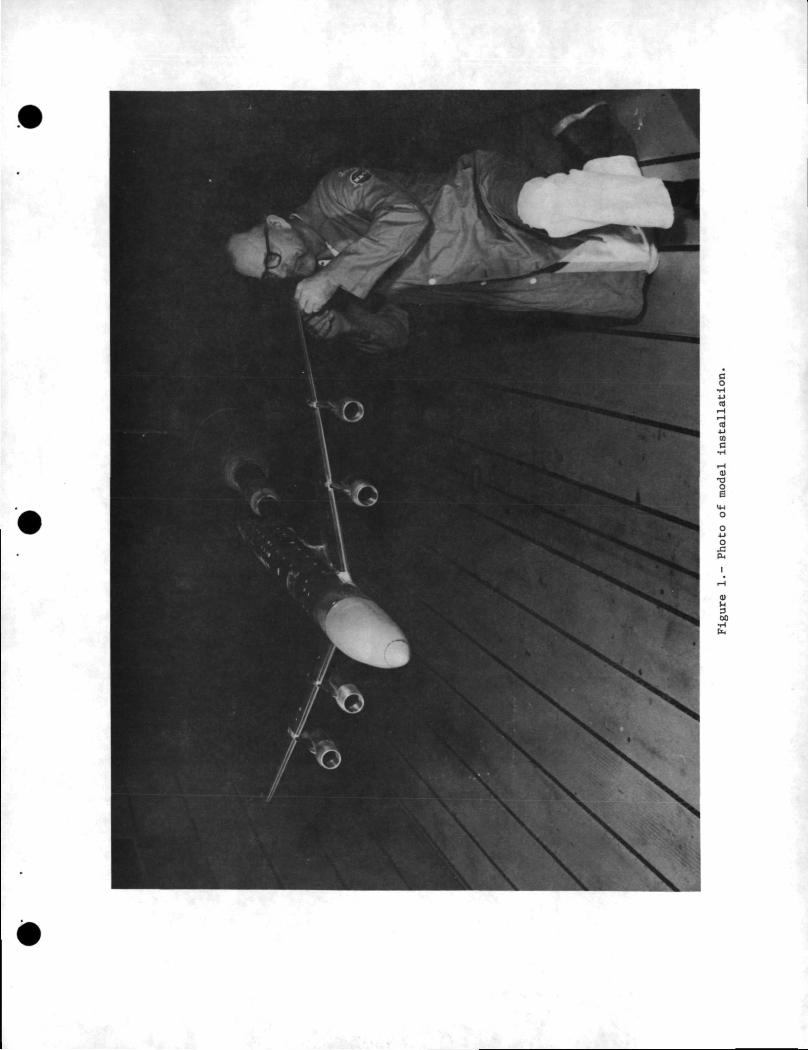
of the model installed in the Ames 11-foot transonic wind tunnel is presented
in Figure 1.
4.1.2 Nacelle Geometry
Because of the larger fan diameter of the JT3D-9 irefan engine, the nacelle
required to enclose the engine and accessories is also larger. The nacelle
geometry is consistent with the maximum-treatment configuration shown in.
Reference 2. In order to retain the proper ground clearance most of the
increased nacelle thickness is taken on the sides with larger kidney ducts,
the exception being that some increased thickness is required on the forward
upper cowling for angle of attack capability. The refan nacelle geometry has
the following characteristics:
1. The inlet length from the engine face to the highlight is 47.8 inches.
2. The maximum nacelle width is 74.3 inches (plan view).
3. The overall nacelle length is 225.5 inches.
4. The nacelle is of long duct design.
5. The afterbody boattail angle is 13.5 degrees.
6. The inlet is canted down 4 degrees relative to the engine centerline
to align it with the local flow angle at cruise conditions.
Since it is impossible to correctly simulate the short-duct fan flow of the
production DC-8-50 and -61 nacelles with flow through nacelles, another set of
JT3D long-duct nacelles was used as the baseline configuration for this. test.
A dimensional sketch of the refan nacelle compared to the baseline nacelle is
presented in Figure 2. '
7

4.1.3 Nacelle Installation Comparison
The refan-engine nacelle installation is compared to the DC-8-50 and -f»l
production short-duct nacelle installation in Figure 3. The proposed refan
pylon has been designed to be compatible with the existing short-duct pylon
structural box and with the existing pylon foot-print on the wing upper and
lower surface (i.e. the refan pylon is a minimum structural change short-duct
pylon). The refan pylon trailing edge extends beyond the existing pylon
trailing edge because of the difference in thrust reverser mechanisms for the
two installations. The bump on the leading edge of the refan pylon would be
required to house a heat exchanger for the cabin airconditioning system.
The baseline set of JT3D long-duct nacelles is mounted on contoured pylons in
an aft position like the refan nacelles and has been found from previous wind
tunnel and flight testing to be an essentially interference-drag free
installation. A comparison of the baseline and refan nacelle installations
is presented in Figure 4.
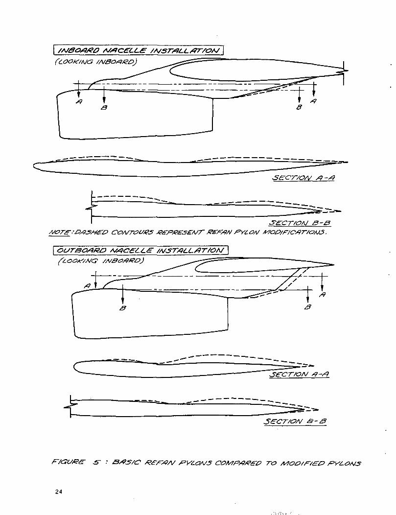
4.1.4 Pylon Modifications
Three sets of modified pylons were designed and fabricated in an attempt to
minimize or eliminate any potential interference drag penalty resulting from
the basic refan nacelle installation. The pylons were designed to improve the
channel area distribution (see the sketch on page 4). The modifications took
the form of forward and aft bumps on the inboard side of the inboard and
outboard pylons. Figure 5 presents a comparison between the basic refan pylons
and the modified pylons. The three pylon sets consist of the forward and aft
bumps individually and in combination.
4.2 TEST APPARATUS
4.2.1 Facility and Model Installation
The NASA Ames Research Center 11- by 11-foot continuous flow variable density
transonic wind tunnel was used for this test program;
The model was mounted on a 2.5-inch diameter internal strain gage balance and
installed on the Ames straight sting No. 9797-D3-6 which was mated to the Ames
straight sting No. 9797-D4-1. This assembly was inserted into the Ames straight

adapter, with 40-Inch extension, which was then mounted on the pitch pod. The
balance cavity in the fuselage center body is at a five degree angle to the
fuselage reference plane, such that, when the model is at zero angle of attack,
the balance is at +5.0 degrees angle of attack.
The model was aligned in pitch and roll by means of leveling bubbles in the
pitch and roll planes embedded in the fuselage centerbody.
A drawing of the actual model installation is presented in Figure 6.
4.2.2 Instrumentation
The force data were gathered with a six-component Mark XIA internal strain
gage balance and the pressure data were gathered with a six-valve scanivalve
module. The model angle of attack was measured by an analog signal conditioner
in the wind tunnel control room. This electronic device was connected to the
balance normal force gages and accounted for sting bend and balance deflections,
thus allowing the tunnel operator to set the desired angle. The model support
sting was instrumented to indicate contact between the fuselage and sting. No
contact was indicated throughout the test.
The location of the static pressure orifices is shown in Figure 7. There are
four rows of pressures in the inboard channel of each nacelle and two in the
outboard channel plus one row on the wing upper surface on the inboard side of
each nacelle. This instrumentation is common to all configurations.
All forces, moments and pressures were recorded on the Ames wind tunnel data
acquisition system.
4.3 TEST PROCEDURE AND DATA ACCURACY
The test was conducted at a constant Reynolds number of 7 million per foot
(5.5 x 10° on the mean aerodynamic chord) through a Mach number range from
0.70 to 0.84. The Reynolds number was held to within +100,000 and the Mach
number to within +0.002 of the specified values. The full Reynolds number
capability, 8 million per foot, was not utilized, because of the concern about
sting divergence at the higher dynamic pressures. Angle of attack was varied

at each Mach number in one-half degree increments over a range corresponding
to lift coefficients between zero and 0.5. The angle of attack tolerance is
+0.1 degree of the indicated value. Selected Mach numbers were repeated to
ensure the validity of the data. The data repeatability was excellent
throughout the test (CD repeated within +0.0001). The pressure data were
gathered at enough Mach numbers to provide the necessary information for
understanding any potential interference problems. All data were gathered
with the horizontal and vertical tails removed.
10

5.0 RESULTS AND DISCUSSION
5.1 BASIC REFAN INSTALLATION
The incremental drag difference between the refan-engine nacelle installation
and the essentially interference-drag free baseline installation is presented
in Figure 8. It can be seen that, within the data scatter, there is a drag
penalty of about two drag counts (AC]) = 0.0002) for the refan installation,
which is independent of Mach number and lift coefficient. About a quarter of
this penalty can be accounted for by the basic parasite drag difference between
the isolated nacelles and pylons. The remaining excess or interference drag
for the refan installation is thus less than 1.5 drag counts (1/2% of total
cruise drag). The magnitude of the interference drag and the fact that it is
independent of Mach number and lift coefficient suggests that this small
penalty is not a result of a wave drag and/or a boundary layer separation
associated with shocks in the wing-pylon-nacelle channel, as was originally
feared from examination of the channel area distributions, but probably results
from a general thickening in the boundary layer of some of the components when
they are integrated. Analysis of the pressure data somewhat substantiates this
conclusion.
Figures 9 and 10 present the refan nacelle, pylon, and wing pressure distri-
butions compared with the baseline distributions for the inboard and outboard
installations at a typical cruise condition (M0 = 0.82, CL = 0.4). It can be
seen in Figure 9 that there is a local region of supersonic flow which extends
across the inboard channel of the inboard installation, but does not extend
down around to the maximum half breadth of the nacelle. The flow in the
remaining three channel areas (outboard channel of inboard nacelle installation,
Figure 9, and both inboard and outboard channels of outboard nacelle instal-
lation, Figure 10) is almost entirely free of any supersonic flow.
The effect of Mach number on the channel pressure distributions is presented
in Figure 11, where it can be seen that there is no supersonic flow in the
wing-pylon-nacelle channels at M0 = 0.70. The fact that the interference drag
penalty shown in the force data (Figure 8) is independent of Mach number would
indicate that the local region of supersonic in the inboard channel of the
inboard nacelle installation at M = 0.82 is not sufficient to cause any wave
drag.
11

The effect of lift coefficient on the channel pressure distributions is presented
in Figure 12 for Mo = 0.82. The maximum local Mach number in the inboard channel
of both the inboard and outboard nacelle installations is slightly higher at
0.3 lift coefficient than it is at 0.4. Again, reference to the force data
(Figure 8) would indicate that this slight increase in local Mach number at the
lower lift coefficient is not sufficient to cause any wave drag.
A comparison of the wing upper surface pressure distributions for the two
nacelle installations is presented in Figure 13. The pressure distributions
are almost identical at both .7 and .82 Mach number.
The very small interference drag penalty (1/2% of total cruise drag) measured
in this test for the installation of the long-duct refan nacelle on the
existing (minimum structural change) Series 50 and 61 short-duct pylon would
be more than off-set by the large improvement of a long-duct nacelle over
a short-duct nacelle. This improvement has been demonstrated on the existing
DC-8 (Series 50 and 61 models compared to Series 62 and 63 models).
5.2 PYLON MODIFICATION
Three sets of modified pylons were designed and fabricated for this test. As
mentioned previously, the purpose of these pylons was to minimize or eliminate
any potential interference drag resulting from shock waves in the wing-pylon-
nacelle channel by improving the channel area distributions (see the sketches
on pages 3 and 4). Since the on-line force-data analysis at the wind tunnel
indicated that the interference drag for the basic refan nacelle installation
was quite small, only one of the modified pylons was tested.
Figure 14 presents the incremental drag difference between the refan instal-
lation with the basic pylon and with the modified pylon having only the aft-
bump. It can be seen that within the data scatter, there is a drag penalty of
over two drag counts (almost 1% of total cruise drag) for the modified pylon.
In view of the fact that the basic refan installation is free of shock-related
interference drag, this result is not suprising. Since the improved area
distribution feature of the bump is not required, it has apparently become
a source of additional parasite drag.
12

6.0 CONCLUSIONS
A high-speed wind tunnel test was conducted in the NASA Ames 11-foot facility
in support of the NASA refan program in order to assess the effect on cruise
performance of installing a long-duct refan-engine nacelle on the DC-8-50 and
-61. Analysis of the results from this test leads to the following conclusions:
1. At a typical cruise condition there exists an interference drag
penalty of less than one-percent total cruise drag for the instal-
lation of the long-duct refan nacelle on the existing (minimum
structural change) Series 50 and 61 short-duct pylon. This very
small penalty would, however, be much more than off-set by the large
improvement, demonstrated on the existing DC-8, of a long-duct
nacelle over a short-duct nacelle.
2. At cruise conditions some supersonic flow is present in the inboard
channel of the inboard refan-nacelle installation, but it is not
sufficient to cause any wave drag or boundary layer separation.
The small interference drag results from a general thickening in the
boundary layer of some of the components when they are integrated.
3. The one pylon modification tested resulted in a drag penalty, because
its design goal of eliminating shock-related interference drag was
not required and this bump thus became a source of additional
parasite drag.
4. From aircraft performance considerations, a common long-duct
refan-engine nacelle is certainly feasible for all DC-8 models.
13

7.0 REFERENCES
1. Kutney, John T. and Piszkin, Stanley P.: Reduction of Drag Rise on the
Convair 990 Airplane. J. Aircraft Vol. 1 No. 1, Jan - Feb 1964.
2. Anonymous: Program on Ground Test of Modified Quiet Clean JT3D and
JT8D Engines in their respective nacelles. DC-8-61 Engine and Nacelle/
Airframe Integration Definition. Douglas Report MDC J573.1,
10 November 1972.
15

Page Intentionally Left Blank

8.0 FIGURES
FIGURE NO^ TITLE
1. Photo of model installation
2. Nacelle geometry
3. Long-duct refan-engine nacelle installation compared to
DC-8-50/61 production installation
4. Long-duct refan-engine nacelle installation compared to test
program baseline installation
*
5. Basic refan pylons compared to modified pylons
6. Model installation drawing
7. Location of static pressure orifices
8. Incremental drag difference between refan and baseline nacelle
installations
9. Refan channel pressure distributions compared to baseline-
inboard nacelle
10. Refan channel pressure distributions compared to baseline-
outboard nacelle
11. Effect of Mach number on refan channel pressure distributions
12. Effect of lift coefficient on refan channel pressure
distributions
13. Effect of refan installation on wing upper surface pressure
distributions
14. Incremental drag due to addition of aft-bump to basic refan
pylon
17
eo
0)•aoe
oo4-1o
oo•HK

Left Blank

I
xl
I
I
21


*1M
23
TO
24

IxlNl
8I
1I
25

S3
(
(r? - . <£//)
23 (>? = . 375-} (2j^7 7
26

27

cooe
SYM
Q
or MUG i.e.4UO PYLOM £ M fUN V/fV
A14CfU£fX/T
28

COVflGUKAT/OfJ
caof
IY tA/re&recne*s of Move i.e.
Ai4CfU£ fK/r
/O
29

t&> rja &a ' £*o m>
30

QCO£FfKIEUT
.3
cooetv
LOCATION Oft/V7E#3£CTM>*/ Of <-.£.
£X/T
of tsrr caeff/c/fA/r
31

q-T-TTrr-p;
f/G</*£ /3
32


DOUGLAS AIRCRAFT COMPANY
3855 Lakewaod Boulevard. Long Beach, California 90846 12131 593-5511
MCDONNELL. DOUGLAS