The Effect of Veneering Materials on Stress Distribution in Implant...
12
COPYRIGHT © 2000 BY QUINTESSENCE PUBLISHING CO, INC. PRINTING OF THIS DOCUMENT IS RESTRICTED TO PERSONAL USE ONLY . NO PART OF THIS ARTICLE MAY BE REPRODUCED OR TRANSMITTED IN ANY FORM WITH- OUT WRITTEN PERMISSION FROM THE PUBLISHER. The International Journal of Oral & Maxillofacial Implants 571 The Effect of Veneering Materials on Stress Distribution in Implant-Supported Fixed Prosthetic Restorations Yalc¸ın C¸iftc¸i, DDS, MS 1 /S¸enay Canay, DDS, MS 2 In this study, the effect of various materials used in fabricating superstructures for implant- retained fixed partial dentures on stress distribution around implant tissues was investigated. Five different mathematical models consisting of 11,361 nodes and 54,598 elements were con- structed to study porcelain, gold alloy, composite resin, reinforced composite resin, and acrylic resin veneering materials using the 3-dimensional finite element analysis method. MARC K7.2/Mentat 3.2 software was used for the analysis. Reference points were determined on the cortical bone, where perpendicular, oblique, and horizontal forces were applied. Stress values created by oblique and horizontal forces appeared to be higher than those created by vertical forces. Stress seemed to be concentrated at the cortical bone around the cervical region of the implant. Gold alloy and porcelain produced the highest stress values in this region. Stresses cre- ated by acrylic resin and reinforced composite resin were 25% and 15% less, respectively, than porcelain or gold alloy. Porcelain and gold alloy produced stress values at the lingual implant sites that reached the ultimate strength values of the cortical bone. (INT J ORAL MAXILLOFAC IMPLANTS 2000;15:571–582) Key words: dental implant, dental materials, dental stress analysis, finite element analysis, fixed partial denture B iomechanical factors play an important role in the long-term survival of oral implants. The selection of implant positions, prosthesis design, and superstructure material is critical for the longevity and stability of the implant prosthesis. 1–7 The nature and magnitude of loads necessary to cause implant loosening are unknown, so it has been recommended that forces be kept to a mini- mum. The osseointegrated implant provides direct contact with bone and has no micromovement. Therefore, all stress waves or shocks applied are transmitted to the implants. Because of the lack of micromovement of osseointegrated implants, most of the force distrib- ution is concentrated on the crest of the ridge, and this may lead to bone resorption and subsequent loss of the implant. It has been suggested that stress-absorbing or load-dampening systems be incorporated into the superstructures supported by osseointegrated implants, so as to reduce loads on the implant that occur because of the lack of vis- coelasticity at the bone-implant interface. The IMZ System (Interpore International, Irvine, CA) has an internal shock absorber made of a medical-grade polyoxymethylene incorporated into its design. 8–10 The manufacturer of the Bråne- mark System (Nobel Biocare, Göteborg, Sweden) has recommended acrylic resin for fabrication of the occlusal surfaces of prostheses. 11 Other researchers have demonstrated that acrylic resin provides a gen- erous layer of material with sufficient cushioning effect to dampen most commonly exerted oral forces and thus acts as a shock absorber. 12–14 How- ever, acrylic resin wears at an accelerated rate when opposed by natural teeth or porcelain. 15,16 Such changes in the occlusal surfaces will reduce chewing efficiency and may alter maxillomandibular rela- tionships. 17 This has led authors to encourage the use of porcelain on occluding surfaces. 18 1 Assistant Professor, Department of Prosthodontics, Faculty of Dentistry, University of Hacettepe, Ankara, Turkey. 2 Associate Professor, Department of Prosthodontics, Faculty of Dentistry, University of Hacettepe, Ankara, Turkey. Reprint requests: Dr S¸enay Canay, Bag˘is ¸ sok. 17/10, 06660 Kocatepe Ankara, Turkey. Fax: 90 (312) 4184715. E-mail: [email protected]
Transcript of The Effect of Veneering Materials on Stress Distribution in Implant...

COPYRIGHT © 2000 BY QUINTESSENCE PUBLISHING CO, INC. PRINTING
OF THIS DOCUMENT IS RESTRICTED TO PERSONAL USE ONLY. NO PART OF
THIS ARTICLE MAY BE REPRODUCED OR TRANSMITTED IN ANY FORM WITH-OUT WRITTEN PERMISSION FROM THE PUBLISHER.
The International Journal of Oral & Maxillofacial Implants 571
The Effect of Veneering Materials on Stress Distribution in Implant-Supported
Fixed Prosthetic Restorations Yalc ın Ciftc i, DDS, MS1/Senay Canay, DDS, MS2
In this study, the effect of various materials used in fabricating superstructures for implant-retained fixed partial dentures on stress distribution around implant tissues was investigated.Five different mathematical models consisting of 11,361 nodes and 54,598 elements were con-structed to study porcelain, gold alloy, composite resin, reinforced composite resin, and acrylicresin veneering materials using the 3-dimensional finite element analysis method. MARCK7.2/Mentat 3.2 software was used for the analysis. Reference points were determined on thecortical bone, where perpendicular, oblique, and horizontal forces were applied. Stress valuescreated by oblique and horizontal forces appeared to be higher than those created by verticalforces. Stress seemed to be concentrated at the cortical bone around the cervical region of theimplant. Gold alloy and porcelain produced the highest stress values in this region. Stresses cre-ated by acrylic resin and reinforced composite resin were 25% and 15% less, respectively, thanporcelain or gold alloy. Porcelain and gold alloy produced stress values at the lingual implantsites that reached the ultimate strength values of the cortical bone. (INT J ORAL MAXILLOFAC
IMPLANTS 2000;15:571–582)
Key words: dental implant, dental materials, dental stress analysis, finite element analysis, fixedpartial denture
Biomechanical factors play an important role inthe long-term survival of oral implants. The
selection of implant positions, prosthesis design,and superstructure material is critical for thelongevity and stability of the implant prosthesis.1–7
The nature and magnitude of loads necessary tocause implant loosening are unknown, so it hasbeen recommended that forces be kept to a mini-mum. The osseointegrated implant provides directcontact with bone and has no micromovement.Therefore, all stress waves or shocks applied aretransmitted to the implants.
Because of the lack of micromovement ofosseointegrated implants, most of the force distrib-ution is concentrated on the crest of the ridge, and
this may lead to bone resorption and subsequentloss of the implant. It has been suggested thatstress-absorbing or load-dampening systems beincorporated into the superstructures supported byosseointegrated implants, so as to reduce loads onthe implant that occur because of the lack of vis-coelasticity at the bone-implant interface.
The IMZ System (Interpore International,Irvine, CA) has an internal shock absorber made ofa medical-grade polyoxymethylene incorporatedinto its design.8–10 The manufacturer of the Bråne-mark System (Nobel Biocare, Göteborg, Sweden)has recommended acrylic resin for fabrication of theocclusal surfaces of prostheses.11 Other researchershave demonstrated that acrylic resin provides a gen-erous layer of material with sufficient cushioningeffect to dampen most commonly exerted oralforces and thus acts as a shock absorber.12–14 How-ever, acrylic resin wears at an accelerated rate whenopposed by natural teeth or porcelain.15,16 Suchchanges in the occlusal surfaces will reduce chewingefficiency and may alter maxillomandibular rela-tionships.17 This has led authors to encourage theuse of porcelain on occluding surfaces.18
1Assistant Professor, Department of Prosthodontics, Faculty ofDentistry, University of Hacettepe, Ankara, Turkey.
2Associate Professor, Department of Prosthodontics, Faculty ofDentistry, University of Hacettepe, Ankara, Turkey.
Reprint requests: Dr Senay Canay, Bagis sok. 17/10, 06660 Kocatepe Ankara, Turkey. Fax: 90 (312) 4184715. E-mail: [email protected]

COPYRIGHT © 2000 BY QUINTESSENCE PUBLISHING CO, INC. PRINTING
OF THIS DOCUMENT IS RESTRICTED TO PERSONAL USE ONLY. NO PART OF
THIS ARTICLE MAY BE REPRODUCED OR TRANSMITTED IN ANY FORM WITH-OUT WRITTEN PERMISSION FROM THE PUBLISHER.
572 Volume 15, Number 4, 2000
CIFTCI/CANAY
Ceramic materials are acceptable for veneeringimplant-supported prostheses, and their use greatlyimproves the esthetics of implant restorations.19
However, porcelain is not a stress-absorbing material,so that forces developed at the occlusal level will betransmitted directly to the prosthesis, the implant, orthe bone interface unless they are mediated in somefashion.10,20 The intensity of the resulting stresseswould be a function of the physical qualities of thedifferent veneering materials used. The thickness ofthe veneering material is greatly reduced when a par-tially edentulous arch is restored. The question arisesas to whether or not resin used as a veneering mater-ial provides a significant cushioning effect.
The finite element analysis (FEA) method hasproved to be a useful tool in estimating stress levelsaround implants. It involves the development of amathematical model of a continuous structuredivided into a system of discrete components or ele-ments. These components are connected at nodalpoints, where stresses and displacements are deter-mined. The accuracy of the 3-dimensional (3-D)method is proportional to the number of nodes andelements in the mathematical model.21,22
The purpose of this study was to analyze, with the 3-D FEA method, the force-absorbingbehavior of 5 restorative materials used to veneersuperstructures that were rigidly connected toimplants.
MATERIALS AND METHODS
In this study, the FEA method was used to evaluatestresses in the mandibular posterior quadrant, wherean implant-supported fixed partial prosthesis wasfabricated with different restorative materials. Theimplants were assumed to be placed in the region ofthe second premolar and second molar, and the firstmolar tooth was assumed to be lost. The model wasprovided with 2 spline hydroxyapatite-coated cylin-dric Calcitek dental implants (Sulzer Calcitek Inc,Carlsbad, CA) 4 mm in diameter and 13 mm inheight. A 3-D mathematical model including aframework, abutments, implants, a bone-implantinterface, and a section of the mandible was con-structed, representing the anatomic geometry of themandible (Fig 1).
Figs 1a to 1d Mathematical model including implants and superstructures.
Fig 1a Section with implants and corti-cal bone.
Fig 1b Section with implants, corticalbone, and trabecular bone. C1 = crest ofcortical bone; C2 = junction between corti-cal and cancellous bone.
Fig 1c Section with implants, corticalbone, trabecular bone, and copings.
Fig 1d Section with implants, corticalbone, trabecular bone, copings, andveneering materials.
1.5 mm
C2C1
Implant 1
Implant 2
13 mm

COPYRIGHT © 2000 BY QUINTESSENCE PUBLISHING CO, INC. PRINTING
OF THIS DOCUMENT IS RESTRICTED TO PERSONAL USE ONLY. NO PART OF
THIS ARTICLE MAY BE REPRODUCED OR TRANSMITTED IN ANY FORM WITH-OUT WRITTEN PERMISSION FROM THE PUBLISHER.
The International Journal of Oral & Maxillofacial Implants 573
CIFTCI/CANAY
An actual human mandible was used in thepreparation of mathematical models. With the helpof laser scanners (3D Digitizer Model 3030 andEcho digitizing software, resolution 1 � 1 mm/30 s,Cyberware, Monterey, CA), the surface topographyof prosthetic superstructures and mandibles wasconverted into digital data. Data were convertedinto a 3-D solid mathematical model by using thesolid and crest modeling programs I-DEAS ArtisanSeries 3 (Structural Dynamics Research Corpora-tion, Milford, OH) and the MARC K7.2/Mentat3.2 FEA program (MARC Analysis Research Cor-poration, Palo Alto, CA). For the analysis, a directprofile was used. In this procedure, the cores ofshell structures were meshed with 4-node tetrahe-dron elements. The analysis program used in thestudy could easily automesh the complicated modelwhen the tetrahedron elements were used. Sincethese nodal points could move in 3 axes, theirdegree of freedom was set at 3. The displacement ofthese nodes assisted in the calculation of stress dis-tribution inside the structures.
To simulate the clinical situation, the model wasnot supported at the bottom; instead, it was fixedalong the points where the masticatory muscleswere inserted. A pilot study (ie, a trial run) showedthat the region where the analyses were done wasnot influenced by the location of the muscle inser-tions. Therefore, the mesh was refined in the areaof implant placement to provide additional stressresolution in this region. The mathematical modelwas divided into 54,598 elements connected at11,361 points, known as nodes.
Mandibular anatomy mandated placement of theposterior implant with a lingual inclination to takeadvantage of the bone height in the model, withmoderate (10-degree) inclination. The modeledsection of the mandible had an 18-mm buccolingualthickness, was 26 mm in height, and was sur-rounded by 1.5 mm of cortical bone.
A superstructure that represented the frameworkof an implant-supported fixed prosthesis was alsomodeled at 4 mm in height and 6 mm in width.The materials used as veneering materials wereType III gold alloy (Sjoding C-3); feldspathicporcelain (Vita VMK 68, Vident, Brea, CA); heat-polymerized polymethylmethacrylate resin(Biotone, Dentsply Co, York, PA); microfilled com-posite resin (Charisma, Heraeus Kulzer, SouthBend, IN); and glass-modified composite resin(Artglass, Heraeus Kulzer). Restorative materialsvaried, but the abutment designs were similar, sothat the resulting stress and stress distributioncould be attributed to the material differences. Thecement layer between the crown and abutment was
too thin to adequately model in the finite elementsimulation and was considered to be negligible.
All materials used in the models were consideredto be isotropic, homogeneous, and linearly elastic.To simulate ideal osseointegration, the implantswere rigidly anchored along their entire interface inthe bone model. Modulus of elasticity and Poisson’sratio values are presented in Table 1.
A wide range of magnitudes for chewing forces hasbeen reported in the literature. For the currentmodel, 3 forces from different directions wereselected: a horizontal bite force (Fh = 0 degrees), avertical bite force (Fv = 90 degrees), and an obliquebite force (Fo = 120 degrees). The proportion of theforce magnitude was Fh : Fv : Fo = 1 : 3.5 : 7.23 In thestudy, a vertical load of 500 N, a horizontal load of142 N, and an oblique load of 1,000 N wereapplied.24 The vertical and oblique loads were appliedequally at the 125 nodal points on the buccal inclina-tion of the lingual cusps. Hence, when the mandibu-lar implant opposes a natural maxillary tooth, the pri-mary contacting cusp becomes the maxillary lingualcusp opposing the mandibular implant crown, withthe mandibular buccal cusp of decreased height andwidth over the implant body.25 The horizontal loadswere applied to the nodal points on the buccal.
Loading forces on the models were static. Stresscontours were computed and plotted in the bone tis-sue. Then by giving a 0.1-mm displacement to thenodes defined in a specific period of time, stress dis-tributions formed on the cortical bone were analyzed.
Before loading, specific points at 2 levels alongthe bone-implant interface were selected for con-venience to directly compare models representingdifferent analysis variables.
Table 1 Mechanical Properties of Oral Tissuesand Prosthetic Materials in FEA Evaluations
Modulus ofelasticity Poisson’s
GPa ratio (v)
Cortical bone 13.7 0.30Cancellous bone 1.37 0.30Titanium 117 0.33Metal coping (Ceramco O)* 86.2 0.33Full-crown Type III gold alloy 100 0.33
(Sjoding C-3)Porcelain (Vita VMK 68) 70 0.19Glass-modified composite resin 10 0.30
(Artglass)Acrylic resin (Biotone) 2.26 0.35Composite resin (Charisma) 14.1 0.24
*Ceramco/Dentsply, Weybridge, Surrey, England.

COPYRIGHT © 2000 BY QUINTESSENCE PUBLISHING CO, INC. PRINTING
OF THIS DOCUMENT IS RESTRICTED TO PERSONAL USE ONLY. NO PART OF
THIS ARTICLE MAY BE REPRODUCED OR TRANSMITTED IN ANY FORM WITH-OUT WRITTEN PERMISSION FROM THE PUBLISHER.
574 Volume 15, Number 4, 2000
CIFTCI/CANAY
1. The crest of the cortical bone (C1). Three pointswere chosen at the buccal and lingual aspects ofboth the first and second implants, which wereplaced in the second premolar and second molarregion, as reference (Fig 1b).
2. The junction between the cortical and cancellousbone (C2). Two points were chosen for the sec-ond implant, and 3 points were chosen for thefirst implant on the buccal and lingual aspects(Fig 1b).
For an evaluation of stress distribution, the mag-nitudes of the concentrations were presented inprincipal stresses. The principal stress offers thepossibility of making a distinction between tensilestress and compressive stress. Displacement compo-nents of specific points provide information aboutthe deformation of the model and facilitate interpre-tation of the results. The magnitude of the stressesfrom these reference points was evaluated for eachof the 5 different veneering materials. Principalstress values of fragile compact bone were comparedwith the ultimate compressive strength and ultimatetensile strength values.
The use of statistical analyses was very limitedfor the FEA studies because the results of the modelobservations were invariant.
RESULTS
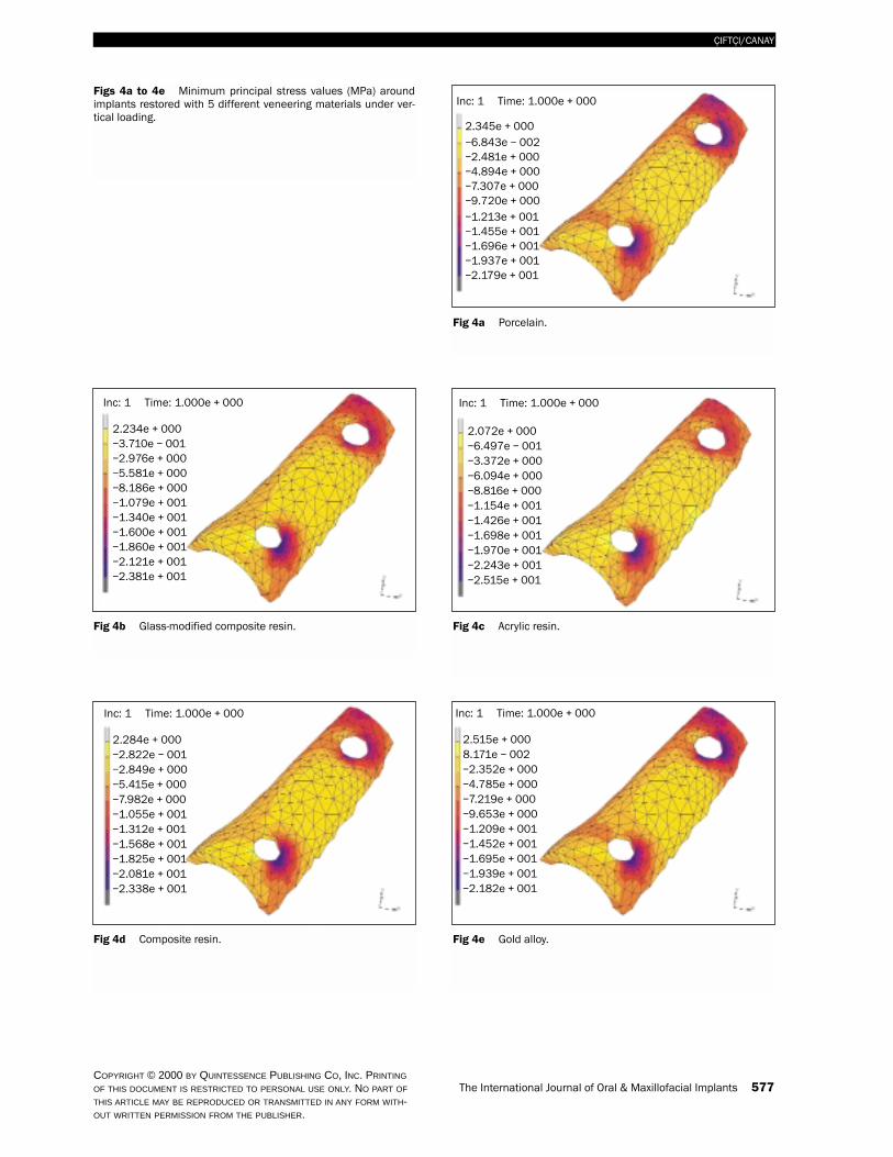
Stress patterns appeared as contour lines with dif-ferent color connecting equistress points betweencertain limits. The stress value for each contour linewas presented as a positive or negative; positive val-ues identified tensile stresses, while negative valuesidentified compressive stresses. For an evaluation ofstress distribution, the magnitude of the concentra-tions was presented in minimum (compressivestress) and maximum (tensile stress) principal stress,together with their location in relation to theimplant. Maximum and minimum principal stressvalues that resulted from vertical and oblique load-ing conditions on the bone-implant interfaces andthe cortical bone surrounding the neck of theimplants with 5 different veneering materials areillustrated in Figs 2 to 5. Stress contours werecolor-coded and were explained on the left side ofeach figure for both loading magnitudes. Table 2summarizes the magnitude and type of stresses.
The intensity of compressive stress was higherwhen vertical and horizontal loads were transferredto the upper and lower crests of the cortical bonefound at the first implant’s lingual surface. Thesevalues were highest for gold alloy and lowest for the
acrylic resin veneering material. Lower values werealso found for composite resin and glass-modifiedcomposite resin. All the stress values seen at the C2level of the cortical bone show that there was areduction in stress from the C1 level. However,when oblique and horizontal loads were transferredto the C1 and C2 level of the cortical bone on thebuccal crest, compressive stresses were more likelyto be formed.
In this study, tensile and compressive stresseswere evaluated. However, in the regions where themaximum principal and minimum principal stressvalues were similar, the stresses could not bedefined as actually tensile or compressive; there-fore the term complex or mixed stress was used. Onthe C1 level of the cortical bone, when verticalload was transferred, complex stresses were formedonly on the gold alloy and porcelain. In contrast,when acrylic resin, composite resin, and glass-modified composite resin materials were used, ten-sile stress was more likely to occur. Tensile andcompressive stresses that existed on the secondimplant’s lingual and buccal aspects were greaterthan those on the first implant’s lingual and buccalsites. This was true for all 5 veneering materialsunder all 3 loading conditions. Higher stresseswere situated in the upper cortical layer than in thelower regions. Gold alloy had the highest averagetensile stress values observed under vertical,oblique, and horizontal loads, but with porcelain,composite resin, glass-modified composite resin,and acrylic resin, this rate decreased gradually. Onthe buccal aspect of the cortical bone, stresses werecomplex in nature under vertical loading but werepredominantly tensile under horizontal andoblique loading.
Cortical Bone Displacement ResultsIn the study, static analysis findings were considered,and stress rates under applied loads were recorded.After the same amount of load was applied verticallyon the prespecified nodal points, the highest stresslevels that formed on the upper crest of the corticalbone around both implants were observed in themodels where gold alloy and porcelain were used asveneering material, and the lowest stress levels wereobserved in the model in which acrylic resin wasused. Similar conclusions were drawn for the lowercrest of the cortical bone, which showed a decreasein the stress level compared to that of the uppercrest (Figs 6 and 7).

COPYRIGHT © 2000 BY QUINTESSENCE PUBLISHING CO, INC. PRINTING
OF THIS DOCUMENT IS RESTRICTED TO PERSONAL USE ONLY. NO PART OF
THIS ARTICLE MAY BE REPRODUCED OR TRANSMITTED IN ANY FORM WITH-OUT WRITTEN PERMISSION FROM THE PUBLISHER.
The International Journal of Oral & Maxillofacial Implants 575
CIFTCI/CANAY
Figs 2a to 2e Maximum principal stress values (MPa) aroundimplants restored with 5 different veneering materials under ver-tical loading.
Fig 2a Porcelain.
Fig 2b Glass-modified composite resin. Fig 2c Acrylic resin.
Fig 2e Gold alloy.Fig 2d Composite resin.
Inc: 1 Time: 1.000e + 000
1.991e + 0011.731e + 0011.471e + 0011.211e + 0019.505e + 0006.903e + 0004.302e + 0001.701e + 000–9.008e + 001–3.502e + 000–6.104e + 000
Inc: 1 Time: 1.000e + 000
2.000e + 0011.745e + 0011.491e + 0011.236e + 0019.808e + 0007.295e + 0004.710e + 0002.161e + 000–3.877e + 001–2.937e + 000–5.486e + 000
Inc: 1 Time: 1.000e + 000
2.011e + 0011.760e + 0011.508e + 0011.256e + 0011.004e + 0017.524e + 0005.006e + 0002.488e + 000–2.954e + 002–2.547e + 000–5.065e + 000
Inc: 1 Time: 1.000e + 000
1.998e + 0011.742e + 0011.486e + 0011.230e + 0019.736e + 0007.176e + 0004.615e + 0002.054e + 000–5.061e + 001–3.067e + 000–5.627e + 000
Inc: 1 Time: 1.000e + 000
1.998e + 0011.737e + 0011.476e + 0011.215e + 0019.544e + 0006.934e + 0004.325e + 0001.716e + 000–8.932e + 001–3.502e + 000–6.112e + 000

576 Volume 15, Number 4, 2000
CIFTCI/CANAY
COPYRIGHT © 2000 BY QUINTESSENCE PUBLISHING CO, INC. PRINTING
OF THIS DOCUMENT IS RESTRICTED TO PERSONAL USE ONLY. NO PART OF
THIS ARTICLE MAY BE REPRODUCED OR TRANSMITTED IN ANY FORM WITH-OUT WRITTEN PERMISSION FROM THE PUBLISHER.
Figs 3a to 3e Maximum principal stress values (MPa) aroundimplants restored with 5 different veneering materials underoblique loading.
Fig 3a Porcelain.
Fig 3b Glass-modified composite resin. Fig 3c Acrylic resin.
Fig 3e Gold alloy.Fig 3d Composite resin.
Inc: 2 Time: 2.000e + 000
1.031e + 0029.140e + 0017.970e + 0016.801e + 0015.632e + 0014.462e + 0013.293e + 0012.123e + 0019.538e + 000–2.157e + 000–1.385e + 001
Inc: 2 Time: 2.000e + 000
8.580e + 0017.523e + 0016.466e + 0015.409e + 0014.352e + 0013.294e + 0012.237e + 0011.180e + 0011.229e + 000–9.343e + 000–1.991e + 001
Inc: 2 Time: 2.000e + 000
8.229e + 0017.193e + 0016.158e + 0015.123e + 0014.088e + 0013.052e + 0012.017e + 0019.818e + 000–5.342e + 001–1.089e + 001–2.124e + 001
Inc: 2 Time: 2.000e + 000
8.867e + 0017.791e + 0016.716e + 0015.640e + 0014.565e + 0013.489e + 0012.413e + 0011.338e + 0012.624e + 000–8.131e + 000–1.889e + 001
Inc: 2 Time: 2.000e + 000
1.058e + 0029.396e + 0018.208e + 0017.020e + 0015.833e + 0014.645e + 0013.457e + 0012.269e + 0011.081e + 001–1.066e + 000–1.294e + 001
COPYRIGHT © 2000 BY QUINTESSENCE PUBLISHING CO, INC. PRINTING
OF THIS DOCUMENT IS RESTRICTED TO PERSONAL USE ONLY. NO PART OF
THIS ARTICLE MAY BE REPRODUCED OR TRANSMITTED IN ANY FORM WITH-OUT WRITTEN PERMISSION FROM THE PUBLISHER.
The International Journal of Oral & Maxillofacial Implants 577
CIFTCI/CANAY
Figs 4a to 4e Minimum principal stress values (MPa) aroundimplants restored with 5 different veneering materials under ver-tical loading.
Fig 4a Porcelain.
Fig 4b Glass-modified composite resin. Fig 4c Acrylic resin.
Fig 4e Gold alloy.Fig 4d Composite resin.
Inc: 1 Time: 1.000e + 000
2.345e + 000–6.843e – 002–2.481e + 000–4.894e + 000–7.307e + 000–9.720e + 000–1.213e + 001–1.455e + 001–1.696e + 001–1.937e + 001–2.179e + 001
Inc: 1 Time: 1.000e + 000
2.234e + 000–3.710e – 001–2.976e + 000–5.581e + 000–8.186e + 000–1.079e + 001–1.340e + 001–1.600e + 001–1.860e + 001–2.121e + 001–2.381e + 001
Inc: 1 Time: 1.000e + 000
2.072e + 000–6.497e – 001–3.372e + 000–6.094e + 000–8.816e + 000–1.154e + 001–1.426e + 001–1.698e + 001–1.970e + 001–2.243e + 001–2.515e + 001
Inc: 1 Time: 1.000e + 000
2.284e + 000–2.822e – 001–2.849e + 000–5.415e + 000–7.982e + 000–1.055e + 001–1.312e + 001–1.568e + 001–1.825e + 001–2.081e + 001–2.338e + 001
Inc: 1 Time: 1.000e + 000
2.515e + 0008.171e – 002–2.352e + 000–4.785e + 000–7.219e + 000–9.653e + 000–1.209e + 001–1.452e + 001–1.695e + 001–1.939e + 001–2.182e + 001

COPYRIGHT © 2000 BY QUINTESSENCE PUBLISHING CO, INC. PRINTING
OF THIS DOCUMENT IS RESTRICTED TO PERSONAL USE ONLY. NO PART OF
THIS ARTICLE MAY BE REPRODUCED OR TRANSMITTED IN ANY FORM WITH-OUT WRITTEN PERMISSION FROM THE PUBLISHER.
578 Volume 15, Number 4, 2000
CIFTCI/CANAY
Figs 5a to 5e Minimum principal stress values (MPa) aroundimplants restored with 5 different veneering materials underoblique loading.
Fig 5a Porcelain.
Fig 5b Glass-modified composite resin. Fig 5c Acrylic resin.
Fig 5e Gold alloy.Fig 5d Composite resin.
Inc: 2 Time: 2.000e + 000
7.599e + 000–5.813e + 000–1.922e + 001–3.264e + 001–4.605e + 001–5.946e + 001–7.287e + 001–8.628e + 001
–1.131e + 002–9.970e + 001
–1.265e + 002
Inc: 2 Time: 2.000e + 000
1.388e + 001–1.442e + 000–1.676e + 001–3.208e + 001–4.740e + 001–6.271e + 001–7.803e + 001–9.335e + 001–1.087e + 002–1.240e + 002–1.393e + 002
Inc: 2 Time: 2.000e + 000
1.761e + 0011.163e + 000–1.528e + 001–3.173e + 001–4.817e + 001–6.462e + 001–8.107e + 001–9.751e + 001–1.140e + 002–1.304e + 002–1.469e + 002
Inc: 2 Time: 2.000e + 000
1.230e + 001–2.588e + 000–1.748e + 001–3.237e + 001–4.726e + 001–6.215e + 001–7.704e + 001–9.193e + 001–1.068e + 002–1.217e + 002–1.366e + 002
Inc: 2 Time: 2.000e + 000
7.593e + 000–5.639e + 000–1.887e + 001–3.210e + 001–4.534e + 001–5.857e + 001–7.180e + 001–8.504e + 001–9.827e + 001–1.115e + 002–1.247e + 002

The International Journal of Oral & Maxillofacial Implants 579
CIFTCI/CANAY
COPYRIGHT © 2000 BY QUINTESSENCE PUBLISHING CO, INC. PRINTING
OF THIS DOCUMENT IS RESTRICTED TO PERSONAL USE ONLY. NO PART OF
THIS ARTICLE MAY BE REPRODUCED OR TRANSMITTED IN ANY FORM WITH-OUT WRITTEN PERMISSION FROM THE PUBLISHER.
Ta
ble
2M
ag
nitu
de
an
dTy
pe
of P
rincip
al S
tresse
s a
rou
nd
the
Firs
t an
d S
eco
nd
Imp
lan
ts a
t C1
an
d C
2 L
ev
els
Maxim
um
prin
cip
al s
tress (M
Pa)
Min
imu
m p
rincip
al s
tress (M
Pa)
Typ
e o
f stre
ss
Vertic
al
Ob
liqu
eH
oriz
on
tal
Vertic
al
Ob
liqu
eH
oriz
on
tal
Vertic
al
Ob
liqu
eH
oriz
on
tal
LB
LB
LB
LB
LB
LB
LB
LB
LB
Implant 1Level C
1P
orcelain–0.60
4.55–0.20
54.100.50
64.15–17.75
–6.15–86.50
–22.75–95.80
–24.85C
MC
TC
TG
lass-modified
–0.552.75
2.4045.95
3.7055.35
–15.50–7.25
–78.05–24.50
–86.45–28.25
CC
CT
CT
composite resin
Acrylic
resin–0.45
1.955.35
40.257.10
49.10–10.55
–7.85–64.80
–21.50–74.55
–26.15C
CC
TC
TC
omposite resin
–0.503.00
1.8047.55
2.8557.00
–15.90–7.10
–79.55–26.85
–88.20–29.30
CC
CT
CT
Gold alloy
–0.554.95
–0.2055.35
0.1065.45
–18.00–6.00
–87.60–21.60
–97.00–23.45
CM
CT
CT
Level C2
Porcelain
1.334.70
9.4750.00
11.0058.50
–12.27–4.00
–66.67–17.10
–74.73–18.70
CM
CT
CT
Glass-m
odified 1.47
3.2010.13
42.5011.60
51.50–11.00
–4.70–61.53
–22.00–69.13
–24.50C
MC
TC
Tcom
posite resinA
crylicresin
1.402.30
10.2738.10
11.7345.40
–10.33–3.90
–55.60–18.70
–66.00–21.40
CM
CT
CT
Com
posite resin1.40
3.5010.07
43.8011.47
51.60–11.20
–4.60–62.40
–21.40–70.00
–23.70C
MC
TC
TG
old alloy1.27
5.0010.27
51.1011.93
59.60–12.40
–3.90–67.47
–16.10–75.60
–17.60C
MC
TC
T
Implant 2Level C
1P
orcelain2.53
10.27–2.13
63.40–9.33
76.07–20.13
–1.33–120.80
6.93–140.20
5.60C
TC
TC
TG
lass-modified
2.809.20
1.4055.00
1.0066.33
–17.87–2.93
–105.801.73
–123.130.47
CT
CT
CT
composite resin
Acrylic
resin2.00
10.93–11.27
49.67–13.47
64.33–17.60
–0.40–96.34
9.53–117.00
8.87C
TC
TC
TC
omposite resin
2.809.47
0.8056.33
0.3367.67
–18.20–2.67
–111.20–2.33
–124.80–5.07
CT
CT
CT
Gold alloy
2.407.40
–8.7364.60
–10.4076.40
–20.60–1.60
–127.138.80
–142.6010.20
CT
CT
CT
Level C2
Porcelain
3.006.50
8.4035.90
8.8043.40
–13.90–3.70
–70.80–1.40
–78.60–1.50
CM
CT
CT
Glass-m
odified 2.90
5.806.60
31.006.90
37.80–12.40
–4.60–64.20
–4.70–71.20
–4.90C
MC
TC
Tcom
posite resinA
crylicresin
3.003.47
9.8036.24
10.4031.2
–11.60–2.9
–56.40–3.1
–61.30–1.9
CM
CT
CT
Com
posite resin3.00
6.106.70
31.707.00
38.70–12.70
–4.40–65.20
–4.00–72.30
–4.20C
MC
TC
TG
old alloy3.00
6.608.70
36.809.30
44.40–14.30
–3.50–72.10
–1.10–80.00
–1.60C
MC
TC
T
L = lingual; B
= buccal; C
= com
pressive stress; T = tensile stress; M
= m
ixed stress.

DISCUSSION
This study used the 3-D FEA method to comparestress distribution in a mandibular posterior seg-ment in which an implant-supported prosthesis wasfabricated using different types of veneering materi-als. The bone quality and quantity in the cervicalregion may be critical to the long-term success ofdental implants. Its loss could endanger implant sta-bility. The type of veneering material is importantfor conducting the stress generated by static orimpact forces to the lower structures.5,12,25
Since the modulus of elasticity of the compositeresin (14.1 GPa) is higher than that of the glass-modified composite resin and acrylic resin, thismaterial is resistant to fracture during masticationand absorbs maximum energy. On the other hand,porcelain transfers nearly all of the load to the bonebecause of its higher modulus of elasticity (70 GPa).Glass-modified composite and acrylic resins, with alower modulus of elasticity (10 and 2.26 GPa,respectively), transfer minimal load to the bone andabsorb the load.
When findings from this study were analyzed, itwas seen that stress levels to the cortical bone aroundimplants were lower in the models that used acrylicresin, composite resin, or glass-modified compositeresin as veneering materials compared to those withporcelain or gold alloy. Davis and colleagues12 con-cluded that acrylic resin helps to reduce the stressesunder impact conditions, such as those that occurwhen a patient inadvertently bites on a hard object.Gracis and coworkers14 used strain gauges in theirstudy and concluded that microfilled light-cured andheat-cured composite resins and heat-cured poly-methylmethacrylate resin materials showed impactforces that were 50% lower than those of porcelainand or gold alloy. Brånemark11 recommended acrylicresin teeth for occluding surfaces of complete-archprostheses in completely edentulous patients treatedwith implants. He inferred that this material wouldcompensate for the resiliency normally provided bythe periodontium. However, other researchers con-cluded that changing the veneering material on theprosthesis had no significant effect on the stress levelor distribution at the bone-implant interface.5,26
580 Volume 15, Number 4, 2000
CIFTCI/CANAY
COPYRIGHT © 2000 BY QUINTESSENCE PUBLISHING CO, INC. PRINTING
OF THIS DOCUMENT IS RESTRICTED TO PERSONAL USE ONLY. NO PART OF
THIS ARTICLE MAY BE REPRODUCED OR TRANSMITTED IN ANY FORM WITH-OUT WRITTEN PERMISSION FROM THE PUBLISHER.
80
70
60
50
40
30
20
10
0Goldalloy
Porcelain Compositeresin
Glass-modifiedcomposite resin
Acrylicresin
59.50
24.50
56.00
23.20
40.10
17.05
36.50
15.6520.20
9.80
Str
ess
(MPa
)
C1
C2
Material
60
50
40
30
20
10
0Goldalloy
Porcelain Compositeresin
Glass-modifiedcomposite resin
Acrylicresin
39.67
15.31
37.33
14.50
26.73
10.66
24.33
9.7813.47
6.13
Str
ess
(MPa
)
C1
C2
Material
Fig 6 Normal principal stress values (for thedisplacement) around the first implant at bothC1 and C2 levels.
Fig 7 Normal principal stress values (for thedisplacement) around the second implant atboth C1 and C2 levels.
According to the present results under staticloading and impact conditions, the use of acrylicresin reduces the stress that is transmitted to theframework and the cortical bone. Another advan-tage of acrylic resin is the relative ease with which itcan be added to the framework and adjusted whennecessary. However, low resistance to abrasion andfracture are disadvantages to its use.
When the structured occlusal scheme and mor-phology cannot be maintained over time, undesir-able lateral forces may increase.17,27 Glass-modifiedcomposite resins represent an attempt to eliminatethe disadvantages of acrylic and composite resins.Glass-modified composite resins provide wear resis-tance similar to tooth enamel. Inorganic active silicaand microparticles of barium, aluminum, and siliconglass (Ba-Al-Si glass) were found among the glassparticles, which were higher in organic content.Thus glass-modified composite resin is stiffer andmore resistant to fracture.
In light of the high stress calculated for obliqueand horizontal forces in each model, it is importantto create an occlusal scheme that minimizes lateralforce components in planning and fabricating asuperstructure. Buccal cusp inclination was set at 30degrees in the present models, and force was equallydistributed at 125 predetermined nodal points onthe buccal inclination of the lingual cusps. The ulti-mate tensile and compressive strength values of cor-tical bone have been reported as 121.00 MPa and167.00 MPa, respectively.28 In models that usedmetal as the veneering material, compressive stressvalues of a maximum of 119.40 MPa were measuredon the lingual side of the cortical bone of the firstimplant and 157 MPa at the second implant. Thesevalues are very close to the ultimate strength valueof the cortical bone, which is 167 MPa.
This study has demonstrated that stress valuesfound at the C1 and C2 level of bone around theimplant are a function of the veneering material.The compressive stress values on the lingual aspectof the cortical bone around the second implant werehigher than those in the same region of the firstimplant. This may be because of the 10-degree lin-gual inclination of the second implant resultingfrom the natural angulation of the mandible.
Impact forces have more destructive effects onthe bone surrounding the implants and on thesuperstructures. Stress distribution is directlyrelated to the elastic modulus of the veneeringmaterial, ie, the stiffer the material, the more stresswill be transmitted to the bone.
A properly selected prosthetic material will mini-mize forces on implants and consequently reducestresses in the supporting bone. It is impossible to find
every desirable characteristic in a single veneeringmaterial. Acrylic resin reduces impact force; however,it absorbs water easily, which contributes to discol-oration. Porcelain has a higher modulus of elasticitythan acrylic resin, so if it is added to a framework, ascompared to acrylic resin or composite resin, morestress will be taken by the superstructure (under a sta-tic load). The greater wear resistance of porcelain,which may contribute to premature overload on theimplants over time, would indicate a need for cautioususe. Moreover, opposing dentition, as well as the per-sonal characteristics of the patient and potential para-functional mandibular movements, should be noted.
When metal alloy was used as the superstructurematerial, similar characteristics to porcelain in termsof load transfer to the implant and its surroundingswere seen; however, it is esthetically inappropriate.In contrast, composite resins or glass-modified com-posite resins allow the formation of low stress levelsin the bone around the implant, and their estheticqualities are very satisfactory. Particularly with theArtglass system, its increased bonding with themetal framework by the Kevloc system (HereausKulzer), ease of implant placement and working inthe mouth, and the present findings of minimalstress levels under all types of loading provide sig-nificant advantages. Glass particles incorporatedinto the structure add resilience. Thus, it is an alter-native material that can be used comfortably forimplant-supported fixed partial prostheses.
CONCLUSIONS
The mechanical behavior of an implant-supportedframework for which 5 different veneering materialswere used was examined using FEA. The followingconclusions were drawn:
1. For all veneering materials, stress was highestunder horizontal and oblique loading and lowestunder vertical loading.
2. For all models, the most extreme stress valueswere located within the implant collar immedi-ately below the bony crest.
3. Maximum compressive stresses were seen on thelingual aspect of the cortical bone, and these val-ues were very close to approximating the ulti-mate strength of the bone.
4. Resin materials are beneficial in reducing thestresses endured under different loading condi-tions. Acrylic resin or glass-modified compositeresin reduced the stress by 25% and 15%,respectively, when compared to equivalent thick-nesses of porcelain or metal.
The International Journal of Oral & Maxillofacial Implants 581
CIFTCI/CANAY
COPYRIGHT © 2000 BY QUINTESSENCE PUBLISHING CO, INC. PRINTING
OF THIS DOCUMENT IS RESTRICTED TO PERSONAL USE ONLY. NO PART OF
THIS ARTICLE MAY BE REPRODUCED OR TRANSMITTED IN ANY FORM WITH-OUT WRITTEN PERMISSION FROM THE PUBLISHER.

REFERENCES
1. Meijer HIA, Kuiper JH, Starmans FJM, Bosman F. Stressdistribution around dental implants: Influence of superstruc-ture, length of implants, and height of mandible. J ProsthetDent 1992;68:96–102.
2. Kregzde M. A method of selecting the best implant prosthe-sis design option using three-dimensional finite elementanalysis. Int J Oral Maxillofac Implants 1993;8:662–673.
3. Stegaroiu R, Sato T, Kusakari H, Miyakawa O. Influence ofrestoration type on stress distribution in bone aroundimplants: A three-dimensional finite element analysis. Int JOral Maxillofac Implants 1998;13:82–90.
4. Brunski JB. Biomaterials and biomechanics in dental implantdesign. Int J Oral Maxillofac Implants 1988;3:85–97.
5. Papavasiliou G, Kamposiora P, Bayne SC, Felton DA.Three-dimensional finite element analysis of stress distribu-tion around single-tooth implants as a function of bony sup-port, prothesis type, and loading during function. J ProsthetDent 1996;76:633–640.
6. Papavasiliou G, Tripodakis APD, Kamposiora P, Strub JR,Bayne SC. Finite element analysis of ceramic abutment-restoration combinations for osseointegrated implants. Int JProsthodont 1996;9:254–260.
7. Van Rossen IP, Braack LH, Putter C, Groot K. Stress-absorbing elements in dental implants. J Prosthet Dent1990;64:198–205.
8. Holmes DC, Grigsby WR, Goel VK, Keller JC. Compari-son of stress transmission in the IMZ implant system withpolyoxymethylene or titanium intramobile element: A finiteelement stress analysis. Int J Oral Maxillofac Implants 1992;7:450–458.
9. Kirsch A, Ackermann KI. The IMZ osseointegrated system.Dent Clin North Am 1989;33:733–745.
10. Chapman RJ, Kirsch A. Variations in occlusal forces with aresilient internal implant shock absorber. Int J Oral Maxillo-fac Implants 1990;5:369–374.
11. Brånemark P-I.Osseointegration and its experimental back-ground. J Prosthet Dent 1983;50:399–410.
12. Davis D, Rimrott R, Zarb GA. Studies on frameworks forosseointegrated prostheses: Part 2. The effect of addingacrylic superstructure. Int J Oral Maxillofac Implants 1988;3:275–280.
13. Hobkirk JA, Psarros J. The influence of occlusal surfacematerial on peak masticatory forces using osseointegratedimplant-supported prostheses. Int J Oral MaxillofacImplants 1992;7:345–352.
14. Gracis SE, Nicholls JI, Chalupnik JD, Yuodelis RA. Shock-absorbing behaviour of five restorative materials used onimplants. Int J Prosthodont 1991;4:282–291.
15. Mahalick JA, Razaui R, Khan Z. Occlusal wear in prostho-dontics. J Am Dent Assoc 1971;82:154–159.
16. Berge M, Silness J. The pattern and severity of wear of resinfacings in fixed prosthetic restorations in vivo. Int J Prostho-dont 1992;5:269–276.
17. Tanaka Y, Sugimoto T, Tanaka S, Hiranuma K. Develop-ment of a two-piece artificial resin tooth specially designedfor a metal occlusal surface. Int J Prosthodont 1990;3:292–298.
18. Jacobi R, Shillingburg HT, Duncanson MG. A comparisonof the abrasiveness of six ceramic surfaces and gold. J Pros-thet Dent 1991;66:303–309.
19. Tripodakis APD, Strub JR, Kappert HF, Witkowski S.Strength and mode of failure of single implant all-ceramicabutment restorations under static load. Int J Prosthodont1995;8:265–272.
20. Seghi RR, Denry I, Brajevic F. Effects of ion exchange onhardness and fracture toughness of dental ceramics. Int JProsthodont 1992;5:309–314.
21. Canay S, Hersek N, Akpınar I, Asik Z. Comparison of stressdistribution around vertical and angled implants with finiteelement analysis. Quintessence Int 1996;27:591–598.
22. Van Zyl PP, Grundling LN, Jooste HC, Terblanche E.Three-dimensional finite element model of a humanmandible incorporating six osseointegrated implants forstress analysis of mandibular cantilever prostheses. Int J OralMaxillofac Implants 1995;10:51–57.
23. Koolstra JH, Eijden JV, Weijs WA, Naeije M. A three-dimensional mathematical model of the human masticatorysystem predicting maximum possible bite force. J Biomech1988;21:563–576.
24. Malone WFP, Koth DL (eds). Tylman’s Theory and Practiceof Fixed Prosthodontics, ed 8. St. Louis: IshiyakuEuroAmerica, 1989.
25. Misch CE. Contemporary Implant Dentistry. St. Louis:Mosby-Year Book, 1993.
26. Ismail Y, Kukunas R, Pkpho D, Ibiary W. Comparative studyof various occlusal materials for implant prosthodontics[abstract]. J Dent Res 1989;68:962.
27. Ratledge DK, Smith BGN, Wilson RF. The effect ofrestorative materials on the wear of human enamel. J Pros-thet Dent 1994;72:194–203.
28. O’Brien JW. Dental Materials and their Selection, ed 2.Chicago: Quintessence, 1997:383, 387.
582 Volume 15, Number 4, 2000
CIFTCI/CANAY
COPYRIGHT © 2000 BY QUINTESSENCE PUBLISHING CO, INC. PRINTING
OF THIS DOCUMENT IS RESTRICTED TO PERSONAL USE ONLY. NO PART OF
THIS ARTICLE MAY BE REPRODUCED OR TRANSMITTED IN ANY FORM WITH-OUT WRITTEN PERMISSION FROM THE PUBLISHER.