INTERACTIONS OF WAVES Interference Refraction Diffraction Doppler Effect Polarization.
Abed et al. Iraqi Journal of Science, 2021, Vol. 62, No. 3, pp: 852-860 DOI: 10.24996/ijs.2021.62.3.16
______________________________ *Email: [email protected]
258
The Effect of Polarization Flipping Point on Polarization Dynamics by
Optical Feedback Technique
Ehsan Ali Abed
1, Jassim Mohammed Najim
2, Suaded Salman Ahmed
2
1Department of Physics, University of Anbar, Anbar, Iraq
2Department of Physics, University of Baghdad, Baghdad, Iraq
Received: 10/12/2019 Accepted: 29/5/2020
Abstract The effect of the optical feedback on the polarization flipping point and
hysteresis loop was studied. The polarization flipping occurred at all angles between
the polarizer axis and the laser polarization. The polarization flipping point changed
by an optical feedback occurred at angles from 0° to 90°. Ability of choosing or
controlling the laser polarization was determined by changing the direction of
vertical and horizontal polarization by polarizer rotation in the external cavity from
0° to 90°.
Keywords: Laser; Optical feedback; Polarization flipping point; hysteresis loop
ة تقنية التغذية العكسية البصريةتأثير نقطة تقلب الاستقطاب على ديناميكية الاستقطاب بواسط
2، سوؤدد سلمان احمد2، جاسم محمد نجم1احسان علي عبيد
قدم الفيزياء، جامعة الانبار، الانبار، العراق1 العراققدم الفيزياء، جامعة بغداد، بغداد، 2
الخلاصةتمت دراستو. تقلب الاستقطاب التأخيرالتغذية العكدية البصرية على نقطة تقلب الاستقطاب وحلقة تأثير
حدث عند كل الزوايا بين محهر المدتقطب واستقطاب الليزر. تغير نقطة تقلب الاستقطاب بهاسطة التغذية امكانية اختيار او الديطرة على استقطاب الليزر حدد 90o . الى 0oالعكدية البصرية يحدث عند الزوايا من
0Oبهاسطة تغيير الاتجاه للاستقطاب العمهدي والافقي بهاسطة تدوير المدتقطب في التجهيف الخارجي من . 90Oالى
1. Introduction
Polarization is a very fundamental property of light that is necessary to consider for the vertical
characteristics of electromagnetic waves. Many approaches in optics are decided through the
polarization states of the considered beams. Recently, studies on the polarization of light in lasers
with optical feedback have attracted remarkable attention [1-4]. Floch et al. observed polarization
switches and a hysteresis effect via changing the intracavity anisotropy values of the laser [1, 5].
Stephan et al. experimentally and theoretically studied the polarization adjustments brought about by
means of optical feedback from a polarizer that is external to the cavity [6].
With the aid of the reflecting part of the laser output back into the resonant cavity, the conduct of the
laser, in particular the static and dynamic residences, can be appreciably affected. This is called the
optical feedback effect, or self-mixing interference, which was first suggested by king and Steward
ISSN: 0067-2904
Abed et al. Iraqi Journal of Science, 2021, Vol. 62, No. 3, pp: 852-860
258
[7]. Theoretically, and to verify experimentally the polarization switching techniques happening in a
gas laser when an internal parameter along with the laser frequency as an example turned into various
[8].
This paper includes the following steps:
1. The polarization flipping point leads to the production of the hysteresis loop (HL) between the
horizontal (//) and vertical (⊥) polarization for the He-Ne laser. The HL leads to a decrease in the two
components of intensity (I// and I⊥).
2. This problem is treated by optical feedback from the external cavity or reflector (M3).
3. In previous investigations, researchers took few angles for optical feedback by polarizer rotation in
the external cavity for the treatment of this problem.
4. In our paper, we took multiple angles for optical feedback by polarizer rotation in the external
cavity. Therefore, the two components intensity values (I// and I⊥) became high and the HL size
became small. The results in our research are remarkably different from those in previous studies.
2. Experimental setup
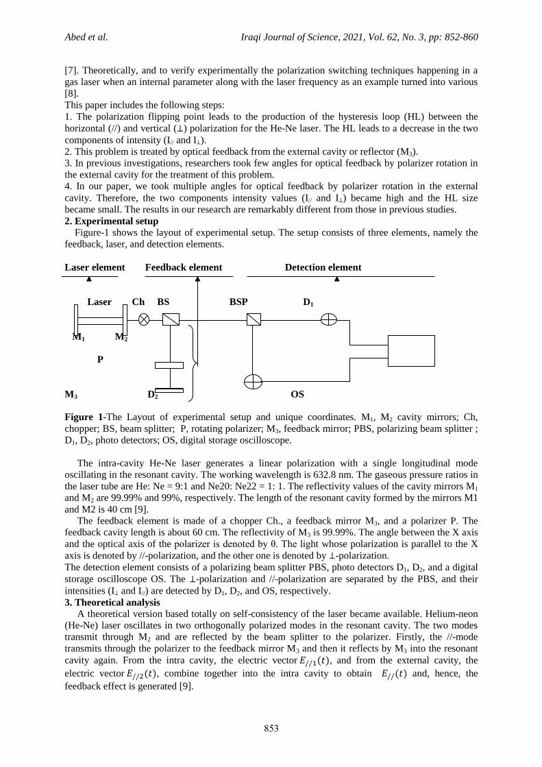
Figure-1 shows the layout of experimental setup. The setup consists of three elements, namely the
feedback, laser, and detection elements.
Laser element Feedback element Detection element
Laser Ch BS BSP D1
M1 M2
P
M3 D2 OS
Figure 1-The Layout of experimental setup and unique coordinates. M1, M2 cavity mirrors; Ch,
chopper; BS, beam splitter; P, rotating polarizer; M3, feedback mirror; PBS, polarizing beam splitter ;
D1, D2, photo detectors; OS, digital storage oscilloscope.
The intra-cavity He-Ne laser generates a linear polarization with a single longitudinal mode
oscillating in the resonant cavity. The working wavelength is 632.8 nm. The gaseous pressure ratios in
the laser tube are He: Ne = 9:1 and Ne20: Ne22 = 1: 1. The reflectivity values of the cavity mirrors M1
and M2 are 99.99% and 99%, respectively. The length of the resonant cavity formed by the mirrors M1
and M2 is 40 cm [9].
The feedback element is made of a chopper Ch., a feedback mirror M3, and a polarizer P. The
feedback cavity length is about 60 cm. The reflectivity of M3 is 99.99%. The angle between the X axis
and the optical axis of the polarizer is denoted by θ. The light whose polarization is parallel to the X
axis is denoted by //-polarization, and the other one is denoted by ⊥-polarization.
The detection element consists of a polarizing beam splitter PBS, photo detectors D1, D2, and a digital
storage oscilloscope OS. The ⊥-polarization and //-polarization are separated by the PBS, and their
intensities (I⊥ and I//) are detected by D1, D2, and OS, respectively.
3. Theoretical analysis
A theoretical version based totally on self-consistency of the laser became available. Helium-neon
(He-Ne) laser oscillates in two orthogonally polarized modes in the resonant cavity. The two modes
transmit through M2 and are reflected by the beam splitter to the polarizer. Firstly, the //-mode
transmits through the polarizer to the feedback mirror M3 and then it reflects by M3 into the resonant
cavity again. From the intra cavity, the electric vector , and from the external cavity, the
electric vector , combine together into the intra cavity to obtain and, hence, the
feedback effect is generated [9].
Abed et al. Iraqi Journal of Science, 2021, Vol. 62, No. 3, pp: 852-860
258
( ⁄ )
[ ⁄ ] )
According to the self-consistency of the laser, the following equation is produced
4)
( ⁄ ) [ ⁄
] 5)
where r1, r2, r3 and rbs are the reflection coefficient of M1, M2, M3, and the beam splitter,
respectively, t2 is the transmission coefficient of M2, and Tp and Tch are the transmissivity values of the
polarizer and chopper, respectively. is the factor brought about through Jones matrix for polarizers
[7]
…………………(6)
is the frequency of horizontal polarization (//-polarization). L and l are the laser cavity and the
feedback cavity lengths, respectively. is the linear gain per unit length due to the simulated
emission inside the resonant cavity with the availability of the external feedback.
Equations (4) and (5) can be solved to obtain [10–12]
(
) (7)
(
)
( )
where
where and represent the gain with and without feedback, respectively. When vertical
polarization (⊥-polarization) oscillates, the following equation can be obtained
where and represent the gain with and without feedback, respectively.
is the factor brought about through Jones matrix for polarizers
As illustrated in Eqs. (9) and (10), and are both modulated by θ (from the rotating
polarizer) and feedback cavity length l. Furthermore, there is a phase difference between and
due to the frequency difference between and . By supposing that is larger than ,
is denoted as which may be expressed as in eq . (12)
(
) 12)
where . is modulated by l, θ and Δν . The amplitude of is denoted as G ,
which is modulated by θ and Δν.
Abed et al. Iraqi Journal of Science, 2021, Vol. 62, No. 3, pp: 852-860
255
0 20 40 60 80 100
0.0
0.2
0.4
0.6
0.8
1.0
/degree
Fig.2. g changes along with .(throretically)
Fig.(2) gain different with theta
g
g
g
0 20 40 60 80 100
0.2
0.3
0.4
0.5
0.6
0.7
0.8
0.9
1.0
G
/degree
Fig.3 G changes along with. (theoretically)
G=g//-g
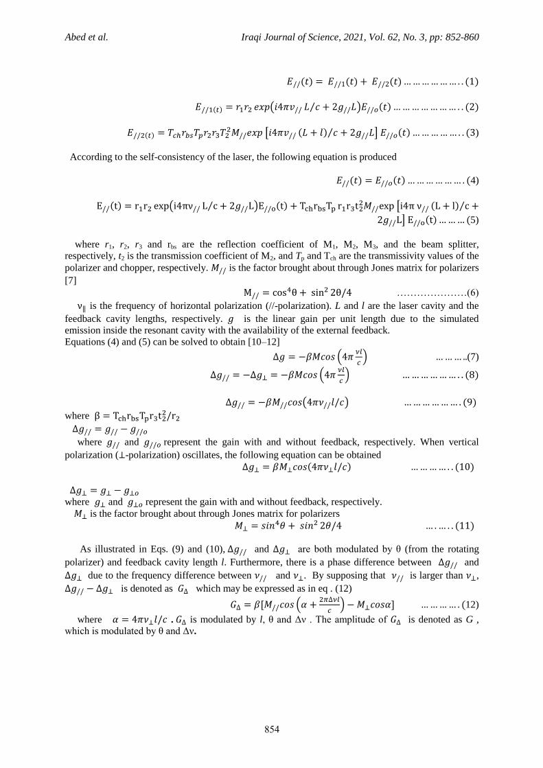
Figure 2-indicates that changes with θ from the rotating polarizer. for horizontal polarization
increases at θ=0 then decreases at θ=90. for vertical polarization decreases at θ=0 then increases
at θ=90. The polarization flipping occurs at θ=45. Figure-3 indicates that G changes along with θ.
Also, G increases with the increase of θ. There is no polarization flipping at any angle.
The laser intensity with optical feedback can be expressed as [13]
where k is a constant relating to the laser operation parameters and is the initial laser intensity
without optical feedback.
By substituting Eq. (9) and Eq.(10) into Eq.(13), the intensities of the two modes with optical
feedback can be written as
* (
)+
[ (
)]
where and are the intensities of the two polarized modes without optical feedback.
and are the intensities of the two polarized modes with optical feedback.
0 20 40 60 80 100
0.0
0.5
1.0
1.5
2.0
I/IO
degree
Fig.4 /changes along with .(throretically)
///
//
/
⊥
0 20 40 60 80 100
0
500
1000
1500
2000
2500
3000
In
te
nsity
degree
Fig. 5.Intensity changes along with (experimentally)
//
I
//I
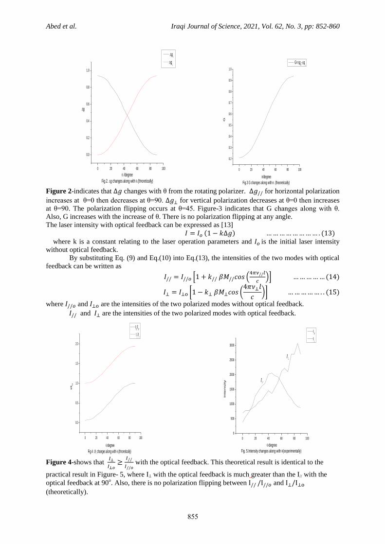
Figure 4-shows that
with the optical feedback. This theoretical result is identical to the
practical result in Figure- 5, where I⊥ with the optical feedback is much greater than the I// with the
optical feedback at 90o. Also, there is no polarization flipping between and
(theoretically).
Abed et al. Iraqi Journal of Science, 2021, Vol. 62, No. 3, pp: 852-860
258
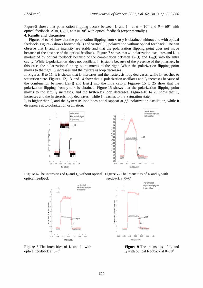
Figure-5 shows that polarization flipping occurs between I// and I⊥ at and with
optical feedback. Also, I⊥ ≥ I// at with optical feedback (experimentally ).
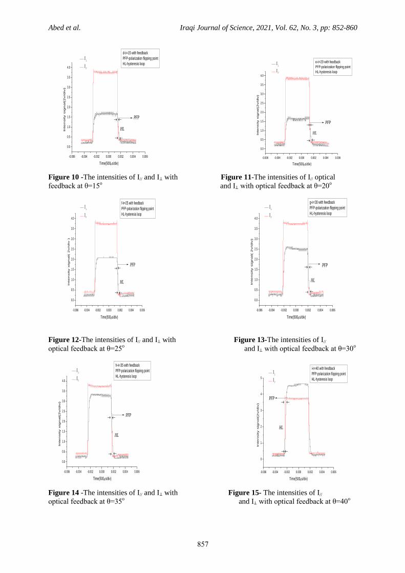
4. Results and discussion Figures- 6 to 14 show that the polarization flipping from x-to-y is obtained without and with optical
feedback. Figure-6 shows horizontal(//) and vertical(⊥) polarization without optical feedback. One can
observe that I// and I⊥ intensity are stable and that the polarization flipping point does not move
because of the absence of the optical feedback. Figure-7 shows that //- polarization oscillates and I// is
modulated by optical feedback because of the combination between E//1(t) and E//2(t) into the intra
cavity. While ⊥-polarization does not oscillate, I⊥ is stable because of the presence of the polarizer. In
this case, the polarization flipping point moves to the right. When the polarization flipping point
moves to the right, I// increases and the hysteresis loop decreases.
In Figures- 8 to 11, it is shown that I// increases and the hysteresis loop decreases, while I// reaches to
saturation state. Figures- 12, 13, and 14 show that ⊥-polarization oscillates and I⊥ increases because of
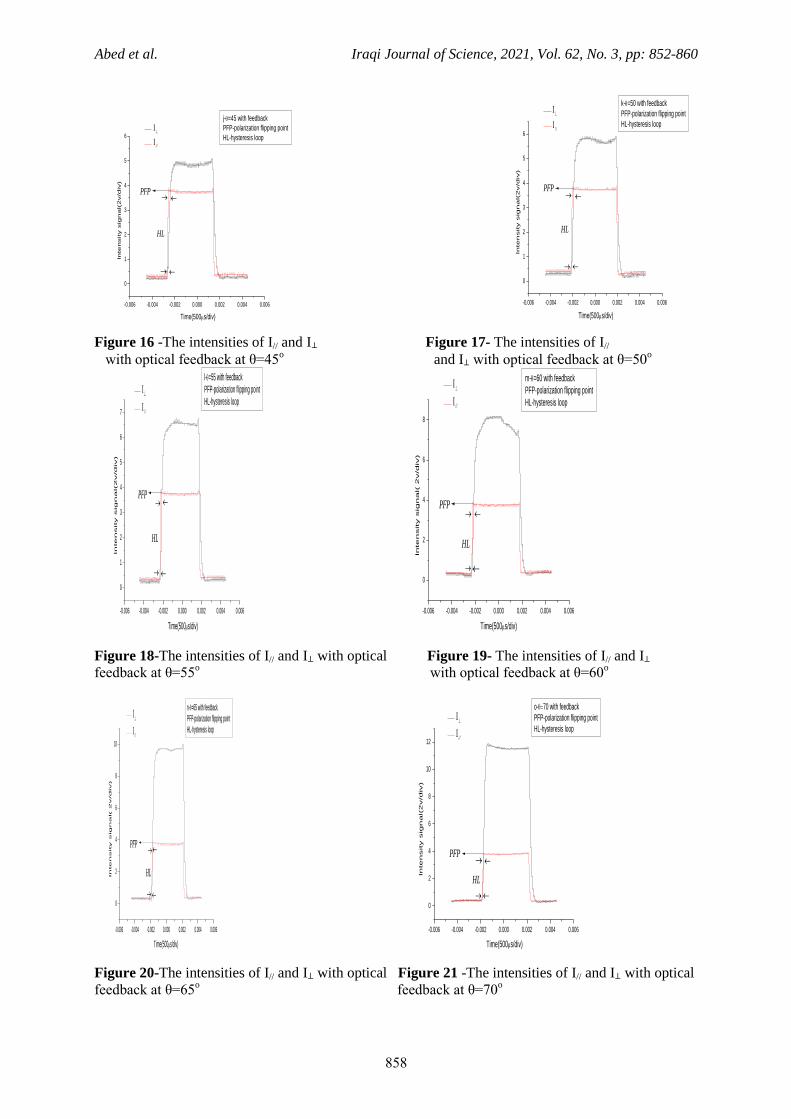
the combination between E⊥1(t) and E⊥2(t) into the intra cavity. Figures- 15 to 25 show that the
polarization flipping from y-to-x is obtained. Figure-15 shows that the polarization flipping point
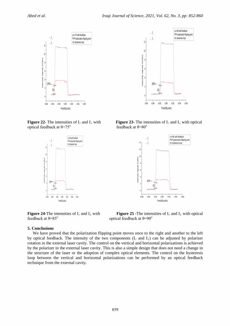
moves to the left, I⊥ increases, and the hysteresis loop decreases. Figures-16 to 25 show that I⊥
increases and the hysteresis loop decreases, while I⊥ reaches to the saturation state.
I⊥ is higher than I// and the hysteresis loop does not disappear at - polarization oscillation, while it
disappears at ⊥-polarization oscillation.
-0.006 -0.004 -0.002 0.000 0.002 0.004 0.006
0.0
0.2
0.4
0.6
0.8
1.0
1.2
1.4
1.6
In
te
nsity sig
na
l(2
v/d
iv)
Time (500s/div)
a-without feedback
PFP-polarization flipping point
HL-hysteresis loop
PFP
//
HL
-0.006 -0.004 -0.002 0.000 0.002 0.004 0.006
0.0
0.2
0.4
0.6
0.8
1.0
1.2
1.4
1.6
1.8
2.0
2.2
2.4
2.6
2.8
3.0
In
te
nsity sig
na
l( 2
V/d
iv)
Time(500s/div)
b-=0 with feedback
PFP-polarization flipping point
HL-hysteresis loop
PFP
//
HL
Figure 6-The intensities of I// and I⊥ without optical Figure 7- The intensities of I// and I⊥ with
optical feedback feedback at θ=0o
-0.006 -0.004 -0.002 0.000 0.002 0.004 0.006
0.0
0.5
1.0
1.5
2.0
2.5
3.0
3.5
4.0
In
te
nsity sig
na
l(2
v/d
iv)
Time (500s/div)
c-=5 with feedback
PFP-polarization flipping point
HL-hysteresis loop
PFP
//
HL
-0.006 -0.004 -0.002 0.000 0.002 0.004 0.006
0.0
0.5
1.0
1.5
2.0
2.5
3.0
3.5
4.0
In
te
nsity sig
na
l( 2
v/d
iv)
Time (500s/div)
c-=10 with feedback
PFP-polarization flipping point
HL-hysteresis loop
PFP
//
HL
Figure 8-The intensities of I// and I⊥ with Figure 9-The intensities of I// and
optical feedback at θ=5o I⊥ with optical feedback at θ=10
o
Abed et al. Iraqi Journal of Science, 2021, Vol. 62, No. 3, pp: 852-860
258
-0.006 -0.004 -0.002 0.000 0.002 0.004 0.006
0.0
0.5
1.0
1.5
2.0
2.5
3.0
3.5
4.0 In
ten
sity s
ign
al(
2v/d
iv)
Time(500s/div)
d-=15 with feedback
PFP-polarization flipping point
HL-hysteresis loop
PFP
//
HL
-0.006 -0.004 -0.002 0.000 0.002 0.004 0.006
0.0
0.5
1.0
1.5
2.0
2.5
3.0
3.5
4.0
In
ten
sity s
ign
al(
2v/d
iv)
Time(500s/div)
e-=20 with feedback
PFP-polarization flipping point
HL-hysteresis loop
PFP
//
HL
Figure 10 -The intensities of I// and I⊥ with Figure 11-The intensities of I// optical
feedback at θ=15o and I⊥ with optical feedback at θ=20
o
-0.006 -0.004 -0.002 0.000 0.002 0.004 0.006
0.0
0.5
1.0
1.5
2.0
2.5
3.0
3.5
4.0
In
te
nsity sig
na
l( 2
v/d
iv )
Time(500s/div)
f-=25 with feedback
PFP-polarization flipping point
HL-hysteresis loop
PFP
//
HL
-0.006 -0.004 -0.002 0.000 0.002 0.004 0.006
0.0
0.5
1.0
1.5
2.0
2.5
3.0
3.5
4.0
In
ten
sity s
ign
al(
2v/d
iv)
Time(500s/div)
g-=30 with feedback
PFP-polarization flipping point
HL-hysteresis loop
PFP
//
HL
Figure 12-The intensities of I// and I⊥ with Figure 13-The intensities of I//
optical feedback at θ=25o and I⊥ with optical feedback at θ=30
o
-0.006 -0.004 -0.002 0.000 0.002 0.004 0.006
0.0
0.5
1.0
1.5
2.0
2.5
3.0
3.5
4.0
In
te
nsity sig
na
l(2
v/d
iv)
Time(500s/div)
h-=35 with feedback
PFP-polarization flipping point
HL-hysteresis loop
PFP
//
HL
-0.006 -0.004 -0.002 0.000 0.002 0.004 0.006
0
1
2
3
4
5
In
te
nsity sig
na
l(2
v/d
iv)
Time(500s/div)
i-=40 with feedback
PFP-polarization flipping point
HL-hysteresis loop
PFP
//
HL
Figure 14 -The intensities of I// and I⊥ with Figure 15- The intensities of I//
optical feedback at θ=35o and I⊥ with optical feedback at θ=40
o
Abed et al. Iraqi Journal of Science, 2021, Vol. 62, No. 3, pp: 852-860
252
-0.006 -0.004 -0.002 0.000 0.002 0.004 0.006
0
1
2
3
4
5
6
In
ten
sity s
ign
al(
2v/d
iv)
Time(500s/div)
j-=45 with feedback
PFP-polarization flipping point
HL-hysteresis loop
PFP
//
HL
-0.006 -0.004 -0.002 0.000 0.002 0.004 0.006
0
1
2
3
4
5
6
In
te
nsity sig
na
l(2
v/d
iv)
Time(500s/div)
k-=50 with feedback
PFP-polarization flipping point
HL-hysteresis loop
PFP
//
HL
Figure 16 -The intensities of I// and I⊥ Figure 17- The intensities of I//
with optical feedback at θ=45o and I⊥ with optical feedback at θ=50
o
-0.006 -0.004 -0.002 0.000 0.002 0.004 0.006
0
1
2
3
4
5
6
7
In
te
nsity sig
na
l(2
v/d
iv)
Time(500s/div)
l-=55 with feedback
PFP-polarization flipping point
HL-hysteresis loop
PFP
//
HL
-0.006 -0.004 -0.002 0.000 0.002 0.004 0.006
0
2
4
6
8 In
te
nsity sig
na
l( 2
v/d
iv)
Time(500s/div)
m-=60 with feedback
PFP-polarization flipping point
HL-hysteresis loop
PFP
HL
//
Figure 18-The intensities of I// and I⊥ with optical Figure 19- The intensities of I// and I⊥
feedback at θ=55o with optical feedback at θ=60
o
-0.006 -0.004 -0.002 0.000 0.002 0.004 0.006
0
2
4
6
8
10
In
te
nsity sig
na
l( 2
v/d
iv)
Time(500s/div)
n-=65 with feedback
PFP-polarization flipping point
HL-hysteresis loop
PFP
//
HL
-0.006 -0.004 -0.002 0.000 0.002 0.004 0.006
0
2
4
6
8
10
12
In
te
nsity sig
na
l(2
v/d
iv)
Time(500s/div)
o-70 with feedback
PFP-polarization flipping point
HL-hysteresis loop
PFP
//
HL
Figure 20-The intensities of I// and I⊥ with optical Figure 21 -The intensities of I// and I⊥ with optical
feedback at θ=65o feedback at θ=70
o
Abed et al. Iraqi Journal of Science, 2021, Vol. 62, No. 3, pp: 852-860
258
-0.006 -0.004 -0.002 0.000 0.002 0.004 0.006
0
2
4
6
8
10
12
In
te
nsity sig
na
l( 2
v/d
iv)
Time(500s/div)
p-=75 with feedback
PFP-polarization flipping point
HL-hysteresis loop
PFP
//
HL
-0.006 -0.004 -0.002 0.000 0.002 0.004 0.006
0
2
4
6
8
10
12
In
te
nsity sig
na
l( 2
v/d
iv)
Time(500s/div)
q-=80 with feedback
PFP-polarization flipping point
HL-hysteresis loop
PFP
//
HL
Figure 22- The intensities of I// and I⊥ with Figure 23- The intensities of I// and I⊥ with optical
optical feedback at θ=75o feedback at θ=80
o
-0.006 -0.004 -0.002 0.000 0.002 0.004 0.006
0
2
4
6
8
10
12
In
te
nsity sig
na
l( 2
v/d
iv)
Time(500s/div)
r-=85 with feedback
PFP-polarization flipping point
HL-hysteresis loop
PFP
//
HL
-0.006 -0.004 -0.002 0.000 0.002 0.004 0.006
0
2
4
6
8
10
12
14
In
te
nsity sig
na
l( 2
v/d
iv)
Time(500s/div)
s-=90 with feedback
PFP-polarization flipping point
HL-hysteresis loop
PFP
//
HL
Figure 24-The intensities of I// and I⊥ with Figure 25 -The intensities of I// and I⊥ with optical
feedback at θ=85o optical feedback at θ=90
o
5. Conclusions We have proved that the polarization flipping point moves once to the right and another to the left
by optical feedback. The intensity of the two components (I// and I⊥) can be adjusted by polarizer
rotation in the external laser cavity. The control on the vertical and horizontal polarizations is achieved
by the polarizer in the external laser cavity. This is also a simple design that does not need a change in
the structure of the laser or the adoption of complex optical elements. The control on the hysteresis
loop between the vertical and horizontal polarizations can be performed by an optical feedback
technique from the external cavity.
Abed et al. Iraqi Journal of Science, 2021, Vol. 62, No. 3, pp: 852-860
288
References
1. Floch, A. L., Ropars, J. M. and Lenornamd, G. 1984. “Dynamics of laser eigenstates.” Phys. Rev.
Lett. 52: 918–921 (1984).
2. Panajotov K., Arizaleta M., Camarena M. and Thienpont H. 2004. “Polarization switching induced
by short external cavity vertical-cavity surface-emitting lasers” Appl. Phys. Lett. 84: 2763–2765.
3. Chen, Y. C. and Liu, J. M. 1984. “Temperature-dependent polarization behavior of semiconductor
lasers” Appl. Phys. Lett. 45: 731–733.
4. Seo, D. S., Park J. D., Mcinerney J. G. and Osinskia M. 1989. “Compound cavity modes in
semiconductor lasers with asymmetric optical feedback” Appl. Phys. Lett. 54: 990–992.
5. Ropars, G., Floch, A. L. and Naour, R. L. 1992. “Polarization control mechanisms in vectorial
bistable lasers for one-frequency systems” Phys. Rev. A. 46: 623–640.
6. Stephan, G. and Hugon, D. 1985. “Light polarization of a quasi-isotropic laser with optical
feedback” Phys. Rev. Lett. 55: 703–706.
7. Yun, W., Yi-Dong, T., Shu-Lian, Z. and Yan, L. 2013. “Influence of Feedback Level on Laser
Polarization in Polarized Optical Feedback” Chin. Phys. Lett. 30: 084201-1-4.
8. Ropars, G., Le Floch, A. and Le Naour, R. 1992. “Polarization control mechanisms in vectorial
bistable lasers for one-frequency systems” Physical Review A, 46: 623-640.
9. Yun Wu, Shulian Zhang and Yan Li. 2013. “The intra-cavity phase anisotropy and the polarization
flipping in HeNe laser” Optics Express, 21: 13684- 13690.
10. Acket, G.A., Lenstra, D., Boef, A.D. and Verbeek, B.H. 1984. “The influence of feedback
intensity on longitudinal mode properties and optical noise in index-guided semiconductor lasers,”
Ieee J. Qe. 20: 1163–1169.
11. Tkach, R.W. and Chraplyvy, A.R. 1986. “Regimes of feedback effects in 1.5-μm distributed
feedback lasers,” J. Lightwave Technol. 4: 1655–1661.
12. Wang, W.M., Grattan, K.T.V., Palmer, A.W. and Boyle, W.J.O. 1994. “Self-mixing interference
inside a single mode diode laser for optical sensing applications,” J. Light wave Technol. 12:
1577–1587.
13. Wei, M., Shu-Lian, Z., Lian-Qing, Z., Jun, Z. and Yan, L. 2006. “Optical feedback characteristics
is He-Ne dual frequency lasers” Chin. Phys. Lett. 32: 1188-1191.