THE EFFECT OF CRYOGENIC CUTTING TOOLS ON MACHINING ...
46
THE EFFECT OF CRYOGENIC CUTTING TOOLS ON MACHINING DIFFICULT TO CUT MATERIAL MOHD NAQIB BIN DERANI A project report submitted in partial fulfillment of the requirement for the award of the Degree of Master of Mechanical Engineering Faculty of Mechanical and Manufacturing Engineering Universiti Tun Hussein Onn Malaysia JANUARY 2012
Transcript of THE EFFECT OF CRYOGENIC CUTTING TOOLS ON MACHINING ...

THE EFFECT OF CRYOGENIC CUTTING TOOLS ON MACHINING DIFFICULT TO CUT MATERIAL
MOHD NAQIB BIN DERANI
A project report submitted in partial fulfillment of the requirement for the award of the
Degree of Master of Mechanical Engineering
Faculty of Mechanical and Manufacturing Engineering Universiti Tun Hussein Onn Malaysia
JANUARY 2012

vi
ABSTRAK
Penyelidikan bahan untuk alat pemesinan adalah satu daripada kritikal elemen dalam
pemesinan besi. Ia dikategorikan mengikut peningkatan ketahanan kehausan untuk
memotong bahan yang lebih keras, kuat atau reaktif secara kimia. Dalam proses
pemesinan, kualiti utamanya bergantung kepada permukaan bahan yang dimesin.
Untuk pemesinan bahan yang sukar dipotong, penurunan secara drastik dalam jangka
hayat alat pemesinan membuatkan proses pemesinan menjadi sukar. Inconel 718
adalah aloy yang mempunyai ketahanan termal yang tinggi. Inconel mempunyai
artikel keras yang membuatkan ianya sukar dipotong. Kesukaran pemesinan Inconel
718 menyebabkan jangka hayat mata alat menjadi rendah dan mengasilkan
permukaan yang kasar. Projek ini mengkaji kesan ‘cryogenic treatment’ kepada
kehausan mata alat dan permukaan Inconel 718. Tujuan utama projek ini adalah
untuk menganalisa perbezaan antara ‘cryogenic treated’ dan ‘untreated’ PVD
semasa pemesinan Inconel 718. ‘Flank wear’ dan ‘crater wear’ pada alat pemesinan
akan dikaji. Permukaan Inconel yang telah dimesin juga akan dianalisis. Keputusan
menunjukkan pada kelajuan pemotongan yang rendah, 20 dan 30 m/min serta pada
‘feed rate’ 0.05 and 0.08 mm/tooth, ‘non cryogenic’ PVD adalah lebih baik daripada
‘cryogenic’ PVD. Pada kelajuan pemesinan yang tinggi, ‘cryogenic’ PVD
menghasilkan permukaan yang lebih baik dan kehausan pada mata alat yang lebih
rendah. Parameter optimum yang boleh digunakan untuk memperoleh permukaan
yang baik dan kehausan mata alat yang rendah ialah pada kelajuan 40 m/min dan ke
atas.

v
ABSTRACT
Material developments for the cutting tool is one of the most critical elements in
metal cutting, have always been characterized by an increase in wear resistance to
machine harder, tougher, or chemically reactive materials. In machining processes, a
major quality related output is integrity of the machined part surface. In machining of
difficult to cut material, a drastic decrease in tool-life makes the machining process
even more difficult. Inconel 718 is a high strength thermal resistant material alloy
which was used for this project. It contains hard particles making it a very difficult to
machine. The difficulty of machining Inconel 718 leading to short tool life and poor
surface roughness. This project describes a study on the effects of cryogenic
treatment on tool wear and surface roughness of Inconel 718. The main aim of this
study is to analyze the differences in tool performance between cryogenically treated
and untreated PVD during face mill Inconel 718. The flank wear and crater wear on
cutting tool are studied for specific operating parameters. It was found that at lower
cutting speed, 20 and 30 m/min and lower feed rate, 0.05 and 0.08 mm/tooth, non-
cryogenic PVD cutting tool is better compare to cryogenic PVD cutting tool in term
of surface roughness and tool wear. At high cutting speed, cryogenic PVD produce
low surface roughness and less tool wear. The optimum parameter that can be used to
obtain low surface roughness and less tool flank wear for cryogenic PVD is 40
m/min and above.
vii
CONTENTS
TITLE i
DECLARATION ii
DEDICATION iii
ACKNOWLEDGEMENT iv
ABSTRACT v
CONTENTS vii
LIST OF TABLE x
LIST OF FIGURE xi
LIST OF SYMBOLS AND ABBREVIATIONS xiv
LIST OF APPENDICES xv
CHAPTER 1 INTRODUCTION
1.1 Introduction 1
1.2 Background of the Problem 3
1.3 Problem Statement 3
1.4 Research Justification 3
1.5 Purpose of the Study 4
1.6 Importance of the Study 4
1.7 Scope of the Study 5
1.8 Definition of Terminology 5

viii
CHAPTER 2 LITERATURE REVIEW
2.1 Introduction 7
2.2 Difficult-to-cut Material 7
2.2.1 Inconel 718 8
2.2.2 Machinability of Inconel 718 9
2.2.3 Cutting tool in machining Inconel 718 12
2.3 Machining 13
2.3.1 Cutting condition 15
2.3.2 Introduction to Milling Operation 15
2.3.2.1 Classification of Milling 16
2.3.2.2 Cutting Parameters in Milling 19
2.4 Cutting Tools 22
2.4.1 Cutting tool Classification 22
2.4.2 Cutting tool for Machining Inconel 718 23
2.4.3 Physical Vapor Deposition (PVD) 24
2.5 Cryogenic 25
2.5.1 Cryogenic Temperature 27
2.5.2 Cryogenic Treatment 27
2.5.3 Theory of Cryogenic Treatment 28
2.5.4 Cryogenic Cycle 28
2.5.5 Cryogenic Applications 30
2.5.6 Improving Tool with Cryogenic Treatment 30
2.6 Dry Condition 31
2.7 Tool Wear 32
2.8 Tool Life 35
2.9 Surface Roughness 37

ix
CHAPTER 3 RESEARCH METHODOLOGY
3.1 Research Design Principles 40
3.2 Variables
3.2.1 Cryogenic Treatment Parameters 43
3.2.2 Machining Parameters 43
3.3 Equipments used 44
3.3.1 Cryogenic Treatment Setup 44
3.3.2 Milling machine 45
3.3.3 Workpiece Preparation 47
3.3.4 Cutting Tool Preparation 49
3.4 Measuring Equipment 50
3.4.1 Scanning Electron Microscopy 51
3.4.2 Surface Roughness Tester 52
3.5 Experimental Procedure 53
CHAPTER 4 RESULTS AND DISCUSSION
4.1 Introduction 55
4.2 Surface roughness, Ra 56
4.3 Result on the flank wear 63
4.4 Result of crater wear 75 CHAPTER 5 CONCLUSIONS AND RECOMMENDATIONS
5.1 Conclusion 86
5.2 Recommendation 87
REFERENCES 89
APPENDIX 92

x
LIST OF TABLE
2.1 Boiling points of common cryogenic fluids 26
3.1 Cutting parameters for machining 43
3.2 Specification of the machine 46
3.3 Element Properties of Inconel 718 48
3.4 Typical Mechanical properties 48
3.5 Electrical Properties 49
3.6 Thermal Properties 49
3.7 Specification of PVD cutting insert 50
3.8 Specification Scanning Electron Microscope 52
3.9 Parameter for Surface Roughness Tester 53

xi
LIST OF FIGURES
2.1 Classification in Milling 16
2.2 Up milling rotating direction 17
2.3 Down milling rotating direction 17
2.4 Face milling 20
2.5 (a) A single-point tool showing rake face, flank,
and tool point; and (b) a helical milling cutter,
representative of tools with multiple cutting edges. 23
2.6 Generalize cycle of cryogenic treatment 29
2.7 Various tool wear (ISO 3685-1993) 32
2.8 Surface roughness 38
3.1 a) Schematic representation of the heat treatment
schedule consisting of hardening (Q), deep cryogenic
processing (C) and tempering (T) cycles, and
(b) typical time-temperature profile of a deep cryogenic
processing cycle. 41
3.2 Overall flowchart of the Experiment 42
3.3 Block Diagram off the Cryogenic Equipment 44
3.4 (a) Diagram off the cryogenic equipment (b) Picture of cryo box 45
3.5 Mazak Vertical Center Nexus 410A – II Milling Machine 46
3.6 Dimension of the Workpiece in mm 47
3.7 KC725M Kennametal cutting tool 50
3.8 Specification of the cutting tool 50
3.9 Scanning Electron Microscopy 51
3.10 Surface Roughness Tester 53
4.1 Surface roughness texture 57

xii
4.2 Cutting speed vs. surface roughness for cryogenic
PVD and non-cryogenic PVD cutting tool at feed
rate 0.05 mm/tooth 58
4.3 Cutting speed vs. surface roughness for cryogenic
PVD and non-cryogenic PVD cutting tool at feed
rate 0.08 mm/tooth 59
4.4 Cutting speed vs. surface roughness for cryogenic
PVD and non-cryogenic PVD cutting tool at feed
rate 0.10 mm/tooth 60
4.5 Cutting speed vs. surface roughness for cryogenic
PVD at various feed rate 61
4.6 Cutting speed vs. surface roughness for non-cryogenic
PVD at various feed rate 62
4.7 Cutting speed vs. flank wear for cryogenic and non-cryogenic
PVD at feed rate 0.05mm/tooth 64
4.8 Cutting speed vs. flank wear for cryogenic and non-cryogenic
PVD at feed rate 0.08mm/tooth 65
4.9 Cutting speed vs. flank wear for cryogenic and non-cryogenic
PVD at feed rate 0.10mm/tooth 66
4.10 Cutting speed vs. flank wear for cryogenic PVD at various
feed rate. 67
4.11 Cutting speed vs. flank wear for non-cryogenic PVD at
various feed rate. 68
4.12 Flank wear for cryogenic PVD for feed rate 0.05 mm/tooth 69
4.13 Flank wear for cryogenic PVD for feed rate 0.08 mm/tooth 70
4.14 Flank wear for cryogenic PVD for feed rate 0.10 mm/tooth 71
4.15 Flank wear for non-cryogenic PVD for feed rate 0.05 mm/tooth 72
4.16 Flank wear for non-cryogenic PVD for feed rate 0.08 mm/tooth 73
4.17 Flank wear for non-cryogenic PVD for feed rate 0.10 mm/tooth 74
4.18 Cutting speed vs. crater wear for cryogenic and non-cryogenic
PVD cutting tool at feed rate 0.05mm/tooth 75
4.19 Cutting speed vs. crater wear for cryogenic and non-cryogenic

xiii
PVD cutting tool at feed rate 0.05mm/tooth 76

xiv
4.20 Cutting speed vs. crater wear for cryogenic and non-cryogenic
PVD cutting tool at feed rate 0.08mm/tooth 77
4.21 Cutting speed vs. crater wear for cryogenic PVD cutting
tool at various feed rate 78
4.22 Cutting speed vs. crater wear for non-cryogenic PVD cutting
tool at various feed rate 79
4.23 Crater wear for cryogenic PVD for feed rate 0.05 mm/tooth 80
4.24 Crater wear for cryogenic PVD for feed rate 0.08 mm/tooth 81
4.25 Crater wear for cryogenic PVD for feed rate 0.10 mm/tooth 82
4.26 Crater wear for non-cryogenic PVD for feed rate 0.05 mm/tooth 83
4.27 Crater wear for non-cryogenic PVD for feed rate 0.08 mm/tooth 84
4.28 Crater wear for non-cryogenic PVD for feed rate 0.10 mm/tooth 85

xiv
LIST OF SYMBOLS AND ABBREVIATIONS
A - Approach distance
d - Depth of cut
D - Diameter of milling cutter, mm
f - Feed rate
L - Length
N - Spindle speed, rev/min
Ra - Surface roughness
RMR - Material removal rate
Tm - Time to mill the workpiece
T - Tool life, min
v - Cutting speed
w - width oC - Celsius oF - Fahrenheit oK - Kelvin
CNC - Computer numerical controller
ISO - International Standard of Operation
PVD - Physical Vapor Deposition
SEM - Scanning Electron Microscope
mm - millimeter
m/min - meter per minute
mm/tooth- millimeter per tooth

LIST OF SYMBOLS AND ABBREVIATIONS
A - Approach distance
d - Depth of cut
D - Diameter of milling cutter, mm
f - Feed rate
L - Length
N - Spindle speed, rev/min
Ra - Surface roughness
RMR - Material removal rate
Tm - Time to mill the workpiece
T - Tool life, min
v - Cutting speed
w - width oC - Celsius oF - Fahrenheit oK - Kelvin
CNC - Computer numerical controller
PVD - Physical Vapor Deposition
SEM - Scanning Electron Microscope
mm - millimeter
m/min - meter per minute
mm/tooth- millimeter per tooth

LIST OF FIGURES
2.1 Classification in Milling 16
2.2 Up milling rotating direction 17
2.3 Down milling rotating direction 17
2.4 Face milling 20
2.5 (a) A single-point tool showing rake face, flank,
and tool point; and (b) a helical milling cutter,
representative of tools with multiple cutting edges. 23
2.6 Generalize cycle of cryogenic treatment 29
2.7 Various tool wear (ISO 3685-1993) 32
2.8 Surface roughness 38
3.1 a) Schematic representation of the heat treatment
schedule consisting of hardening (Q), deep cryogenic
processing (C) and tempering (T) cycles, and
(b) typical time-temperature profile of a deep cryogenic
processing cycle. 41
3.2 Overall flowchart of the Experiment 42
3.3 Block Diagram off the Cryogenic Equipment 44
3.4 (a) Diagram off the cryogenic equipment (b) Picture of cryo box 45
3.5 Mazak Vertical Center Nexus 410A – II Milling Machine 46
3.6 Dimension of the Workpiece in mm 47
3.7 KC725M Kennametal cutting tool 50
3.8 Specification of the cutting tool 50
3.9 Scanning Electron Microscopy 51
3.10 Surface Roughness Tester 53
4.1 Surface roughness texture 57

4.2 Cutting speed vs. surface roughness for cryogenic
PVD and non-cryogenic PVD cutting tool at feed
rate 0.05 mm/tooth 58
4.3 Cutting speed vs. surface roughness for cryogenic
PVD and non-cryogenic PVD cutting tool at feed
rate 0.08 mm/tooth 59
4.4 Cutting speed vs. surface roughness for cryogenic
PVD and non-cryogenic PVD cutting tool at feed
rate 0.10 mm/tooth 60
4.5 Cutting speed vs. surface roughness for cryogenic
PVD at various feed rate 61
4.6 Cutting speed vs. surface roughness for non-cryogenic
PVD at various feed rate 62
4.7 Cutting speed vs. flank wear for cryogenic and non-cryogenic
PVD at feed rate 0.05mm/tooth 64
4.8 Cutting speed vs. flank wear for cryogenic and non-cryogenic
PVD at feed rate 0.08mm/tooth 65
4.9 Cutting speed vs. flank wear for cryogenic and non-cryogenic
PVD at feed rate 0.10mm/tooth 66
4.10 Cutting speed vs. flank wear for cryogenic PVD at various
feed rate. 67
4.11 Cutting speed vs. flank wear for non-cryogenic PVD at
various feed rate. 68
4.12 Flank wear for cryogenic PVD for feed rate 0.05 mm/tooth 69
4.13 Flank wear for cryogenic PVD for feed rate 0.08 mm/tooth 70
4.14 Flank wear for cryogenic PVD for feed rate 0.10 mm/tooth 71
4.15 Flank wear for non-cryogenic PVD for feed rate 0.05 mm/tooth 72
4.16 Flank wear for non-cryogenic PVD for feed rate 0.08 mm/tooth 73
4.17 Flank wear for non-cryogenic PVD for feed rate 0.10 mm/tooth 74
4.18 Cutting speed vs. crater wear for cryogenic and non-cryogenic
PVD cutting tool at feed rate 0.05mm/tooth 75
4.19 Cutting speed vs. crater wear for cryogenic and non-cryogenic

PVD cutting tool at feed rate 0.05mm/tooth 76

4.20 Cutting speed vs. crater wear for cryogenic and non-cryogenic
PVD cutting tool at feed rate 0.08mm/tooth 77
4.21 Cutting speed vs. crater wear for cryogenic PVD cutting
tool at various feed rate 78
4.22 Cutting speed vs. crater wear for non-cryogenic PVD cutting
tool at various feed rate 79
4.23 Crater wear for cryogenic PVD for feed rate 0.05 mm/tooth 80
4.24 Crater wear for cryogenic PVD for feed rate 0.08 mm/tooth 81
4.25 Crater wear for cryogenic PVD for feed rate 0.10 mm/tooth 82
4.26 Crater wear for non-cryogenic PVD for feed rate 0.05 mm/tooth 83
4.27 Crater wear for non-cryogenic PVD for feed rate 0.08 mm/tooth 84
4.28 Crater wear for non-cryogenic PVD for feed rate 0.10 mm/tooth 85

xv
LIST OF APPENDICES
APPENDIX TITLE PAGE
A Picture of flank wear 92
B Picture of crater wear 94

CHAPTER 1
INTRODUCTION
This chapter elaborates the main idea of the project including the title of the project,
background of the problem, problem statement, research justification, purpose,
important and scope. This chapter briefly explains about the guidance and information of
the project.
1.1 Introduction
Machining process is one of the oldest types of process that is being used to machine
many kinds of material in this world. It is also known as material removal process. One
of the examples of machining process is milling process. It is widely used in
manufacturing industry. Milling operation is the process of cutting away material by
feeding a workpiece past a rotating multiple tooth cutter. The cutting action of the many
teeth around the milling cutter provides a fast method of machining. The machine for
holds the workpiece, rotating the cutter, and feeding it, is known as milling machine.

This process is widely used for machining on flat surface. Milling process also can be
used for all common hole-machining operations normally done on a drill press. The
capability to do wide variety of machining operations, and its high metal removal rate,
make it very efficient and that is one of the most important machining processes used
nowadays.
Nowadays superalloy Inconel 718 has wide applications in various fields of
engineering. According to D. G. Thakur et al. (2009), approximately about 75% by
weight in the case of aerospace applications and 50% by weight in the case of modern
jet engines are the components made of Inconel 718. Other applications include marine
equipment, nuclear reactors, petrochemical plants, and food processing equipments.
Inconel 718 is a nickel-based superalloy containing niobium (columbium) age-hardening
addition that provides increased strength without decrease in ductility (M. Alauddin et
al., 1998). E.O Ezugawa et al. (2004) stated that Inconel 718 is non-magnetic, oxidation
and corrosion resistance and can be used at high temperature in the range of 217oC to
700oC and at the same time maintain very high strength to weight ratio. Refering to their
mechanical properties about 370 (HB) hardness, 1310 (Mpa) of tensile strength, 1100
(Mpa) yield strength and 11.2 (W/mK) of thermal conductivity, D. Dudzinski et al.
(2004) categorized Inconel 718 as advance material where it provide good tensile,
fatigue, creep and rupture strength. Inconel 718 provides a serious challenge as a work
material during machining due to their unique combination of properties such as high
temperature strength, hardness, and chemical wear resistance. Although these properties
are the desirable design requirements, they pose a greater challenge to manufacturing
engineers due to high temperature and stresses generated during machining. The
machinability of Inconel 718 depends on the cutting tool that been used. Therefore it is
important to choose the right cutting tool to machine this nickel-based alloy. One of a
way is to use cryogenic-treated cutting tool.

1.2 Background of the Problem
Material developments for the cutting tool is one of the most critical elements in metal
cutting, have always been characterized by an increase in wear resistance to machine
harder, tougher, or chemically reactive materials. The execution of cryogenic treatment
on cutting tool materials increases wear resistance, hardness, and dimensional stability
and reduces tool consumption and down time for the machine tool set up, thus leading to
cost reductions (Simranpreet Singh Gill et al., 2010). Although it has been confirmed
that cryogenic treatment can improve the service life of tools, the degree of
improvement experienced remains ambiguous.
1.3 Problem Statement
In machining processes, a major quality related output is integrity of the machined part
surface. In machining of difficult to cut materials, a drastic decrease in tool-life makes
the machining process even more difficult. Machining is intrinsically characterized by
generation of heat and high cutting temperature. At such elevated temperature, the
cutting tool if not enough hot hard may wear out rapidly resulting in increased cutting
forces, dimensional inaccuracy of the product and shorter tool life. In order to increase
the life of cutting tools, the cryogenic treatment was applied to the cutting tools so that it
encountered rapid tool wear when machining difficult to cut materials.
1.4 Research Justification

Conventional cutting fluids are ineffective in controlling the high cutting temperature
and rapid tool wear. Further, they also deteriorate the working environment and lead to
general environmental pollution. Over the past few years, there has been an increase in
interest in the application of cryogenic treatment on different materials. Research has
shown that cryogenic treatment increases product life (Simranpreet Singh Gill et al.,
2010). Barron, R.F. (1982), had shown a significant increase in the wear resistance for
different types of tool and stainless steels. Cryogenic treatment is a process that uses
cryogenic temperature to modify materials properties to enhance their performance.
Most of the research on cryogenic treatment in the area of machining tools and cutting
tool materials has concentrated mainly on tool steels, especially high-speed steel (Jiang
Yong et al., 2011). However, not much research has been done to study the effect of
cryogenic cutting tools on machining difficult-to-cut material especially on Inconel 718.
1.5 Purpose of the Study
The purpose of this research is to study the machining of Inconel 718 on face milling
process by dry condition by using cryogenic treated PVD and non-treated PVD cutting
tools. The specific objective of this study is to determine the effect and correlation of
cutting parameters to the surface roughness and tool wear.
.
1.6 Importance of the Study
The life of cutting tools plays a major role in increasing productivity and, consequently,
is an important economic factor. The tool may be cheap, but to turn it means to interrupt
the machining process, which costs time and, therefore, money. The execution of the
cryogenic treatment on quenched and tempered high speed steel tools increases hardness
and improves the hardness homogeneity, reduces tool consumption and down time for

the equipment set up, thus leading to cost reductions of about 50% (A. Molinari et al.,
2001). This research is important to study the effect and correlation of cryogenic cutting
tool to the surface roughness and tool wear.
1.7 Scope of Study
- To understand the concept of cryogenic treated cutting tool
- To measure various tool wears, surface roughness
- To study the effect of cryogenic cutting tool wear over non-cryogenic treated
tool.
- To study the effect of cutting parameter like cutting speed, feed rate and depth of
cut.
- Cutting velocity – 20, 30, 40, 50 m/min was used
- Feed rate – 0.05, 0.08, 0.10 mm/tooth used
- Depth of cut – 0.5 mm
- The material used is Inconel 718.
- CNC Vertical Milling machine was used to conduct the experiments and
measuring instruments like Scanning Electron Microscopy (SEM) and Surface
Roughness Tester was used to obtain results.
- PVD tool under cryogenic treated condition was used. However, this treatment
done at outside source.
1.8 Definition of Terminology
‐ Absolute zero: The lowest temperature possible at which all molecular motion
ceases. It is equal to −273°C (−459°F) (www.scienceclarified.com)

‐ Kelvin temperature scale: A temperature scale based on absolute zero with a unit,
called the Kelvin, having the same size as a Celsius degree
(www.scienceclarified.com).
‐ Superconductivity: The ability of a material to conduct electricity without
resistance. An electrical current in a superconductive ring will flow indefinitely
if a low temperature (about −260°C) is maintained (www.scienceclarified.com).
‐ Austenite: Solid solution of carbon and other constituents in a particular form of
iron known as γ (gamma) iron. This is a face-centred cubic structure formed
when iron is heated above 910° C (1,670° F); gamma iron becomes unstable at
temperatures above 1,390° C (2,530° F) (www.britannica.com).
‐ Martensite: A solid solution of carbon in alpha-iron that is formed when steel is
cooled so rapidly that the change from austenite to pearlite is suppressed;
responsible for the hardness of quenched steel (www.thefreedictionary.com)
‐ Quenching: The rapid cooling of a workpiece to obtain certain material
properties (http://en.wikipedia.org)
‐ Tempering: Process of improving the characteristics of a metal, especially steel,
by heating it to a high temperature, though below the melting point, then cooling
it, usually in air. The process has the effect of toughening by lessening brittleness
and reducing internal stresses (www.britannica.com)
‐ Cold Working: Altering the shape or size of a metal by plastic deformation.
Processes include rolling, drawing, pressing, spinning, extruding and heading, it
is carried out below the recrystallisation point usually at room temperature.
Hardness and tensile strength are increased with the degree of cold work whilst
ductility and impact values are lowered. The cold rolling and cold drawing of
steel significantly improves surface finish (http://metals.about.com)
Chapter two elaborate the meaning and the information of the project where its
inform the detail about the project and where the ideas, data and information of the
project area collect from various article and journal as a reference in order to understand
the concept of the project. The information and knowledge gain in this chapter is
discussed in the Chapter 2.

CHAPTER 2
LITERATURE REVIEW
2.1 Introduction
This chapter provides literature review of some significant contributions related to the
cryogenic cutting tool when machining difficult-to-cut material. The collection of
information are all related to cryogenically treated and non-treated PVD cutting tool on
machining Inconel 718 which will enlighten valuable information on knowledge in
terms of cryogenic, difficult to cut material, milling process, cutting tool requirements,
dry condition, tool wear, tool life, and surface roughness.
2.2 Difficult to cut material
Advanced engineering materials, such as structural ceramics, titanium alloys, Inconel
alloy, and tantalum offer unique combination of properties like high strength at elevated
temperature, resistance to chemical degradation, and wear resistance. Therefore, these

advanced materials are being used in making components for aerospace, electronics,
defense, paper and pulp, chemical processing, nuclear waste disposal, dental, orthopedic,
and sea water services. This is because of their unique combination of properties like
high strength at elevated temperatures, resistance to chemical degradation and wear
resistance. Ability to maintain these properties at elevated temperatures severely hinders
the machinability of these materials, thus they are generally referred to as difficult to cut
material. These materials are often difficult-to-cut due to their physical and mechanical
properties such as high strength and low thermal conductivity, which make the cutting
forces and cutting temperature very high and lead to a short tool life.
Because of its high thermal performance, nickel-based super alloy has been
widely applied to rocket engine parts, gas turbines, and other machinery. However, it
causes excessive wear of cutting tools during machining because of its rather high
cutting temperature caused by its very poor thermal conductivity (S. Sun et al., 2010).
Therefore, it is clear that more effective methods for enhancing separation of the chip
from the tool and cooling the cutting tool without affecting local heating of the
workpiece are required.
2.2.1 Inconel 718
Nickel-based superaloy such as Inconel 718, containing a niobium (columbium) has
been widely used in the aircraft and nuclear industry due to their exceptional thermal
resistance and their ability to retain mechanical properties at elevated temperature of
service environment over 700oC. Applications of Inconel 718 include marine equipment,
nuclear reactors, petrochemical plants, and food processing equipments. A. Jawaid et al.
(2001) classified nickel-based superaloy as difficult to cut material due to their high
shear strength, work hardening tendency, highly abrasive carbide particles in the
microstructure, strong tendency to weld and form built edge and low thermal
conductivity. They have tendency to maintain their strength at high temperature which is
generated during machining.

Inconel 718 has wide applications in various fields of engineering particularly
where properties such as high temperature resistance, corrosion resistance, creep
resistance, good ductile to brittle transition temperature during low temperature
application, and high strength to weight ratio etc. are of importance. It has been
established that Inconel 718 has good yield strength (550MPa) even an elevated
temperature (760°C). The use of Inconel 718 in such aggressive environments hinges on
the fact that it maintains high resistance to corrosion, mechanical and thermal fatigue,
mechanical and thermal shock, creep, and erosion at elevated temperatures. In aero
engines, these materials are specifically used for the manufacture of turbine blades,
which operate at high temperature and pressure. Inconel 718 retains strength over a wide
temperature range, attractive for high temperature applications where aluminum and
steel would soften.
Inconel 718 provides a serious challenge as a work material during machining
due to their unique combination of properties such as high temperature strength,
hardness, and chemical wear resistance. Although these properties are the desirable
design requirements, they pose a greater challenge to manufacturing engineers due to
high temperature and stresses generated during machining. The two basic problems in
machining of superalloy Inconel 718 are the following:
i. Less tool life due to the work hardening and attrition properties of the alloy.
ii. Metallurgical damage to the workpiece due to very high cutting forces, which
also gives rise to work hardening, surface tearing, and distortion.
2.2.2 Machinability of Inconel 718
When selecting a material, several factors must be considered, including the cost,
strength, resistance to wear, and machinability. The machinability of a material is
difficult to quantify, but can be said to posses the characteristics such as results in a good

surface finish, promotes long tool life, requires low force and power to turn and provides
easy collection of chips.
The machinability index can be significantly affected by the properties of the
material being machined, properties and geometry of the cutting tool, cutting conditions
employed and other miscellaneous factors such as rigidity of the machine tool, cutting
environment, etc. Machining productivity can be significantly improved by employing
the right combination of cutting tools, cutting conditions and machine tool that will
promote high speed machining without compromising the integrity and tolerance of the
machined components.
The machinability also can often be measured in terms of the number of
components produced per hour, the cost of machining the component, or the quality of
the finish on a critical surface. Problems arise because there are so many practitioners
carries out a wide variety of operation, each with different criteria’s of machinability. A
material may have good machinability by one criterion, but poor machinability by
another. Machinability may be assessed by one or more of criteria below:
i. Tool life – the amount of material removed by a tool, under standardized cutting
condition, before the tool performance becomes unacceptable or the tool is worn
by a standard amount.
ii. Limiting rate of metal removal – the maximum rate at which the material can be
machined for a standard short tool life.
iii. Cutting force – the force acting on tool or the power of consumption.
iv. Surface finish – the surface finish achieved under specified cutting condition.
v. Chip shape – the chip shape as it influences the clearance of the chips from the
tool, under standardized cutting condition.
Inconel 718 is widely used for many industrial applications due to its unique
properties. However, machinability of the material is considered to be poor due to its
inherent characteristics. The machinability studies of Inconel 718 had been carried out
by earlier researchers mostly at low or medium cutting speed. Machinability indices

used in such cases have the characteristics such as cutting force, surface roughness,
cutting temperature, etc (D. G. Thakur et al., 2009).
Nickel-based superalloys are widely employed in the aerospace industry, in
particular in the hot sections of gas turbine engines, due to their high-temperature
strength and high corrosion resistance. They are known to be among the most difficult to
cut materials. D. Dudzinski et at. (2004) stated that the properties responsible for the
poor machinability of the nickel-based superalloys, especially of Inconel 718 are:
i. a major part of their strength is maintained during machining due to their high-
temperature properties,
ii. they are very strain rate sensitive and readily work harden, causing further tool
wear,
iii. the highly abrasive carbide particles contained in the microstructure cause
abrasive wear,
iv. the poor thermal conductivity leads to high cutting temperatures up to 1200 °C at
the rake face,
v. nickel-based superalloys have high chemical affinity for many tool materials
leading to diffusion wear,
vi. welding and adhesion of nickel alloys onto the cutting tool frequently occur
during machining causing severe notching as well as alteration of the tool rake
face due to the consequent pull-out of the tool materials,
vii. due to their high strength, the cutting forces attain high values, excite the
machine tool system and may generate vibrations which compromise the surface
quality.
The difficulty of machining resolves into two basic problems: short tool life and
severe surface abuse of machined workpiece. The heat generation and the plastic
deformation induced during machining affect the machined surface. The heat generated
usually alters the microstructure of the alloy and induces residual stresses. Residual
stresses are also produced by plastic deformation without heat. Heat and deformation
generate cracks and microstructural changes, as well as large microhardness variations.

Residual stresses have consequences on the mechanical behaviour, especially on the
fatigue life of the workpieces. Residual stress is also responsible for the dimensional
instability phenomenon of the parts which can lead to important difficulties during
assembly. Extreme care must be taken therefore to ensure the surface integrity of the
component during machining. Most of the major parameters including the choice of tool
and coating materials, tool geometry, machining method, cutting speed, feed rate, depth
of cut, lubrication, must be controlled in order to achieve adequate tool lives and surface
integrity of the machined surface (D. Dudzinski et al. 2004).
According to D. Dudzinski et at. (2004), the mechanics of machining Inconel
718 is not sufficiently understood yet for industrial applications and machining Inconel
718 can be consider as poor machinability because:
i. This material keeps its mechanical properties at high temperature.
ii. Carbides included in the material increase greatly the abrasive wear.
iii. Low thermal conductivity leads to high temperature during machining.
iv. Nickel-based alloys have a chemical affinity giving diffusion wear.
v. Cutting forces are quite high during the machining.
2.2.3 Cutting tool in machining Inconel 718
Nowadays, the revolution in manufacturing especially in the aerospace industries was
encourage to the need for new and more developments on tool material. D. Dudzinski et
at. (2004) state that the requirements for any cutting tool material used for machining
nickel-based alloys should include:
i. Good wear resistance
ii. High hot hardness
iii. High fracture toughness
iv. High thermal shock properties
v. Adequate chemical stability at elevated temperature

vi. High yield strength at cutting temperature
Turning, milling and drilling are common operations carried out in the manufacture of
jet engine mounts and blades, while turning and drilling are the predominant machining
operations in the manufacture of disks for gas turbines. Most published work on the
machining of nickel-based alloys deal with turning, then with milling, while drilling has
received little attention (D. Dudzinski et at. 2004).
2.3 Machining
Machining can be defined as the process of removing material from a workpiece in the
form of chips. The term metal cutting is used when the material is metallic. Machining is
a family of shaping operations, the common feature of which is removal of material
from a starting work part so the remaining part has the desired geometry. In order to
increase the life of cutting tools, a common approach used in the past has been to heat
treat tool materials, which provides greater control over the range of properties for a
given tool material. In terms of annual dollars spent, machining is the most important of
the manufacturing processes. The fundamental techniques of machining were
established with the beginning of the mass production technology, pioneered by Henry
Ford’s transfer lines. Machining operations consumes a large amount of money annually
worldwide. Over US$ 100 billion is spent annually worldwide on metal part finishing
processes such as turning, milling, boring and other cutting operations.
It is also known that the machining industry converts about 10% of all the metal
produced into swarf (wastage). It is envisaged that up to 20% savings should be possible
by using the correct choice of tooling and machining conditions. The key benefits of
machining are listed below:
i. It is generally regarded as the optimum way to produce prototype or limited
number production run components.
ii. It has the least effect on the properties of materials.

iii. It can be used to generate the most conceivable surface contours, dimensional
tolerances and surface textures.
iv. It can be applied to all available materials.
The importance and versatility of machining process can be further appreciated by
the fact that nearly every device in the society has one or more machined surfaces or
holes. Typical problems that can be associated with machining operations range from
the high cost of consumable tooling and set up time for high volume production to
components often requiring several machining operations, thereby making it difficult to
effectively control the machine shop and consequently an increase in work in process.
These, in addition to the large amount of scrap produced, tend to form the basis for
continued research and development activities in this area of manufacturing technology.
Machining still remains a major industrial activity despite recent significant
developments in near-net shape forming techniques.
The machining system consist of cutting tool, workpiece and machine tool with the
cutting tool playing a major role as the cutting speed employed depend to a greater
extent on the cutting tool materials. Machinists are continually exploring a cutting tool–
machine tool–workpiece combination which will allow rapid metal removal rate for
roughing cuts with large depth of cuts at very fast speeds and will also produce required
surface finishes and dimensional accuracy associated with finishing passes. To achieve
this efforts have been made in developing cutting tool materials that can survive
aggressive conditions at the cutting edges (E.O. Ezugwu, 2005). Machining process can
be divided into three processes as below:
i. Machining – material removal by a sharp cutting tool, e.g., turning, milling,
drilling
ii. Abrasive processes – material removal by hard, abrasive particles, e.g., grinding
iii. Nontraditional processes - various energy forms other than sharp cutting tool to
remove material

2.3.1 Cutting Condition
Three dimensions of a machining process:
a) Cutting speed, v – m/min
b) Feed, f – mm/tooth
c) Depth of cut, d – mm
For certain operations, material removal rate, RMR is calculated using Equation 1.
RMR = v f d (1)
where v = cutting speed; f = feed; d = depth of cut
2.3.2 Introduction to Milling Operation
Milling is the process of cutting away material by feeding a workpiece past a rotating
multiple tooth cutter. The cutting action of the many teeth around the milling cutter
provides a fast method of machining. The machined surface may be flat, angular, or
curved. The surface may also be milled to any combination of shapes. The machine for
holding the workpiece, rotating the cutter, and feeding it is known as the Milling
machine.
The geometric form created by milling is a plane surface. Other work geometries
can be created either by means of the cutter path or the cutter shape. Owing to the
variety of shape possible and its high production rates, milling is one of the most
versatile and widely used machining operations.
Milling is an interrupted cutting operation: the teeth of the milling cutter enter
and exit the work during each revolution. This interrupted cutting action subject the

teeth to a cycle of impact force and thermal shock on every rotation. The tool material
and cutter geometry must be designed to withstand these conditions. (Groover M.P,
2007)
Milling is characterized with an interrupted cutting action where each tooth
produces a chip of variable thickness. The cutting circumstances are more adverse than
that in turning. Since nickel alloys work harden rapidly, once the milling cutter starts
cutting, it will become more and more difficult to further machining due to the
hardening effect. H.Z. Li et al. (2006) said that when the cutting edge is not sharp
enough, the metal is pushed instead of cut. This will result in higher cutting force and
higher temperature.
2.3.2.1 Classification in Milling
Figure 2.1: Classification in Milling (Kalpakjian S., Schmid S., 2006)
There are two types of milling operation that are peripheral milling and face milling. In
peripheral (or slab) milling, the milled surface is generated by teeth located on the
periphery of the cutter body. The axis of cutter rotation is generally in a plane parallel to
the workpiece surface to be machined. In this milling, the rotating direction of the cutter
distinguished two form of milling:
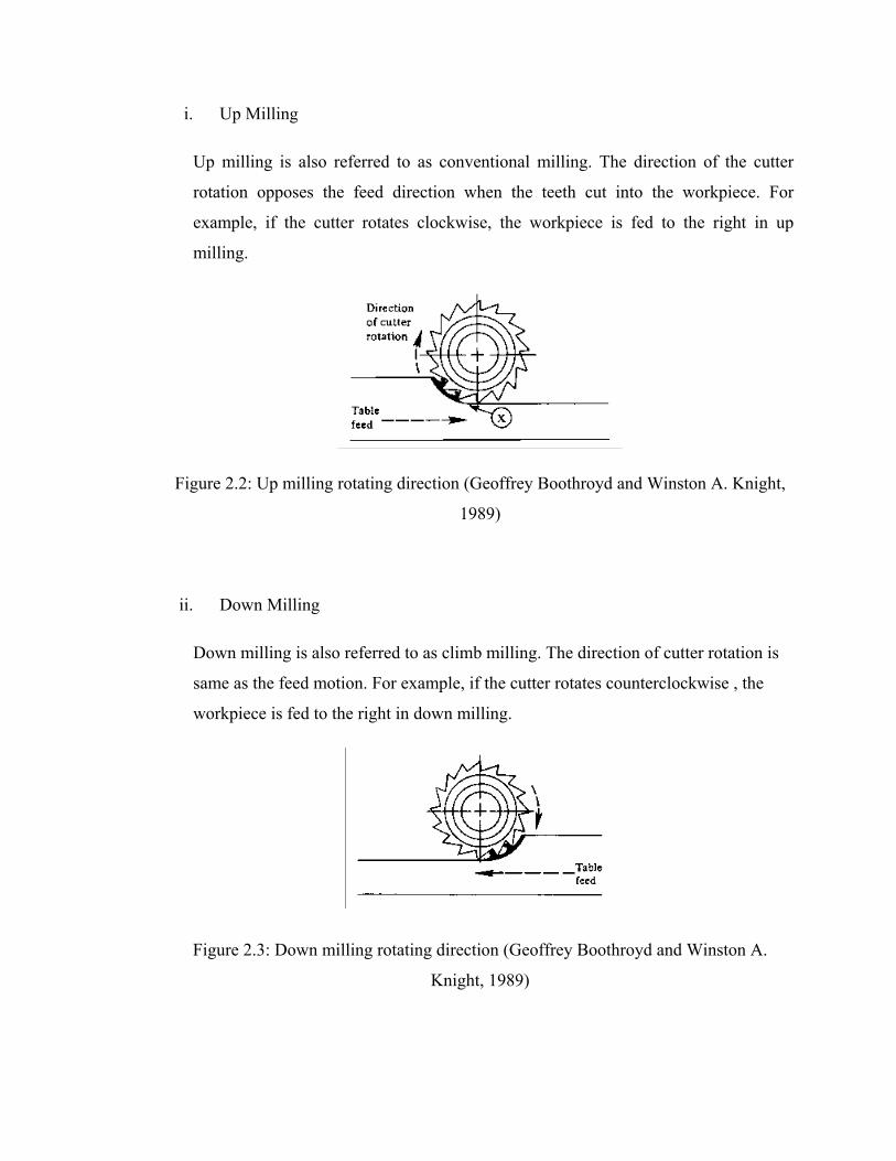
i. Up Milling
Up milling is also referred to as conventional milling. The direction of the cutter
rotation opposes the feed direction when the teeth cut into the workpiece. For
example, if the cutter rotates clockwise, the workpiece is fed to the right in up
milling.
Figure 2.2: Up milling rotating direction (Geoffrey Boothroyd and Winston A. Knight,
1989)
ii. Down Milling
Down milling is also referred to as climb milling. The direction of cutter rotation is
same as the feed motion. For example, if the cutter rotates counterclockwise , the
workpiece is fed to the right in down milling.
Figure 2.3: Down milling rotating direction (Geoffrey Boothroyd and Winston A.
Knight, 1989)

The chip formation in down milling is opposite to the chip formation in up milling. The
figure for down milling shows that the cutter tooth is almost parallel to the top surface of
the workpiece. The cutter tooth begins to mill the full chip thickness. Then the chip
thickness gradually decreases.
The experiment conducted by H.Z. Li et al. (2006) shown that the development
of flank tool wear more rapid for up milling than down milling. There were six cutting
passes performed for the down milling cases and four cutting passes performed for the
up milling cases. For the cases of down milling, the width of flank wear was about
0.1mm after the first cutting pass. After the sixth cutting pass, the width of flank wear
was about 0.3mm. The width of flank wear for up milling was over 0.2mm even after the
first cutting pass. After the fourth cutting pass, it reached as high as 0.5mm, compared
with the width of flank wear of only 0.19-0.25mm for the down milling cases after the
same cutting pass.
In face milling, the cutter is mounted on a spindle having an axis of rotation
perpendicular to the workpiece surface. The milled surface results from the action of
cutting edges located on the periphery and face of the cutter. There are several types of
face milling such as:
i. Conventional face milling – the diameter of the cutter is greater than the
workpiece width, so the cutter overhangs the work on both.
ii. Partial face milling – the cutter overhangs the work on only one side.
iii. End milling - The cutter in end milling generally rotates on an axis vertical to the
workpiece. It can be tilted to machine tapered surfaces. Cutting teeth are located
on both the end face of the cutter and the periphery of the cutter body.
iv. Profile milling – a form of end milling in which the outside periphery of a flat
part is cut.
v. Pocket milling – used to mill shallow pockets into flat parts.
vi. Surface contouring – a ball nose cutter is fed back and forth across the work
along a curvilinear path at close intervals to create a three-dimensional surface
form.

In a milling process, cyclic thermal and mechanical stress are the two effective
factors that play significant role in controlling the tool life, failure modes and wear
mechanism.
2.3.2.2 Cutting Parameters in Milling
In milling, the speed and motion of the cutting tool is specified through several
parameters. These parameters are selected for each operation based upon the workpiece
material, tool material, tool size, and more.
1. Cutting speed - The speed of the workpiece surface relative to the edge of the
cutting tool during a cut, measured in m/min.
2. Feed rate - The speed of the cutting tool's movement relative to the workpiece as
the tool makes a cut. The feed rate is measured in mm/tooth.
3. Depth of cut - The depth of the tool along the axis of the workpiece as it makes a
cut, as in a facing operation. A large axial depth of cut requires a low feed rate,
or else it will result in a high load on the tool and reduce the tool life. Therefore,
a feature is typically machined in several passes as the tool moves to the
specified axial depth of cut for each pass.

Figure 2.4: Face milling (http://www.vulcanmold.com/article/Milling.html)
The cutting speed is determined at the outside diameter of a milling cutter. This can be
converted to spindle rotation speed using formula:
N = v/πD
where
N= Spindle rotation D = diameter of milling cutter, mm; v= cutting speed, m/min
Material removal rate in milling is determined using the product of the cross-section area
of the cut and the feed rate. Accordingly, if a slab-milling operation cutting a workpiece
with width, w, at a depth, d, the material removal rate is:
RMR = wdf
This equation can be applied to end milling, side milling, face milling and other milling
operation making the proper adjustment in the computation of cross-sectional area of
cut.

The time required to milling a workpiece of length, L must account for the approach
distance required to fully engage the cutter. First, consider the case of slab milling, to
determine the time to perform a slab milling operation, the approach distance, A to reach
full cutter depth is given by:
where,
d = depth of cut, mm; D = diameter of milling cutter, mm. The time to mill the
workpiece Tm is therefore
Tm = (L+A) / f
For face milling, it is customary to allow for the approach distance. A plus an over-travel
distance, LO. There are two possible cases as shown in Figure 2.6, in both cases LA = LO.
The first case is when the cutter is centered over the rectangular workpiece, A and O are
each equal to half the cutter diameter. That is,
LA = LO = D/2
where,
D = cutter diameter,mm
The second case is when the cutter is offset to one side of the work. In this case, the
approach and over travel distance are given by
A = O =
Where w = width of the cut,mm. Machining time in either case is therefore given by:
Tm = (L+A) / f

2.4 Cutting Tools
Many types of tool materials, ranging from high carbon steel to ceramics and diamonds,
are used as cutting tools in today’s metalworking industry. It is important to be aware
that differences do exist among tool materials. The best tool is the one that has been
carefully chosen to get the job done quickly, efficiently, and economically. A cutting
tool must have the following characteristics in order to produce good quality and
economical parts:
1. Hardness — hardness and strength of the cutting tool must be maintained at
elevated temperatures, also called hot hardness.
2. Toughness — toughness of cutting tools is needed so that tools don’t chip or
fracture, especially during interrupted cutting operations.
3. Wear Resistance — wear resistance means the attainment of acceptable tool life
before tools need to be replaced.
2.4.1 Cutting Tool Classification
1. Single-Point Tools
• One dominant cutting edge
• Point is usually rounded to form a nose radius
• Turning uses single point tools
2. Multiple Cutting Edge Tools
• More than one cutting edge
• Motion relative to work achieved by rotating
• Drilling and milling use rotating multiple cutting edge tools

Figure 2.5: (a) A single-point tool showing rake face, flank, and tool point; and (b) a
helical milling cutter, representative of tools with multiple cutting edges.
2.4.2 Cutting tool for Machining Inconel 718
Success in metal cutting depends upon the selection of the proper cutting tool (material
and geometry) for a given material (E. Paul Degarmo et al., 1984). In this research,
Inconel 718 is the material that will be machined. The requirement for the tool that will
be machining Inconel 718 are wear resistance, high hot hardness, high strength and
toughness, good thermal shock properties, adequate chemical stability at elevated
temperature. According to E.M Trent (2000), cutting tools that usually used when
milling Inconel 718 are:
i. Cemented carbides
ii. Synthetic diamond and CBN
iii. Ceramics
iv. High-speed steels
v. Cermets
vi. Coated carbides

2.4.3 Physical Vapor Deposition (PVD)
The introduction of PVD for cuttings tool in the metal cutting industry is one of the main
success stories in the industrial application of modern coating technology over the last
30 years. The first PVD coating material to have a commercial application on cutting
tool was TiN in the early 1980s and since the 1990s most cutting tools are PVD coated
particularly in applications where sharp edges are required such as threading, grooving,
end-milling, etc and in cutting applications that have a high demand for a tough cutting
edge like drilling. In solid carbide cutting tools (end-mills and drills), PVD is the
standard coating technology. The TiAIN coating is currently the most widely deposited
PVD coating for cutting tools but other coatings such as TiCn and CrN offer better
solutions in certain applications.
In the areas of machining and tooling, PVD coatings are widely used to increase
the life and productivity of production cutting tools saving companies billions of dollars
worldwide. The use of PVD coatings on cutting tools saves money in three ways. Firstly
PVD coated cutting tools can be run faster reducing cycle times and enabling the
production of more components in less time. Secondly, it can reduce wear and pickup. In
metal cutting different wear processes exist depending on the workpiece material. These
wear mechanism include abrasive wear on the flank and clearance face of the cutting
tool, crater wear on the rake face, caused by the chemical interaction between the cut
chip and the tool surface, built-up edge on the cutting edge and depth-of-cut notching
caused by abrasion by the outer edge of the chip. None of these wear mechanism exists
in isolation however one usually predominates. For example when cutting low-silicon
aluminum a built-up-edge is generated that affects the quality of the finished product
whereas high-silicon aluminum causes the tool to wear predominantly due to abrasion.
PVD coatings are resistant to all forms of wear increasing the life of cutting tools
reducing tool-changing costs.
Thirdly, the PVD coatings on cutting tools reduce the need for cutting fluid.
Cutting fluids cost companies today up to 15% of their total production cost. High speed
cutting and dry machining involve extremely high temperatures at the cutting edge. PVD

89
REFERENCES
A. Altin, M. Nalbant and A. Taskesen (2007) The effects of cutting speed on tool
wear and tool life when machining Inconel 718 with ceramic tools, Material
and design Journal, 28: 2518-2522,
A. Jawaid, S. Koksal, S. Sharif (2011) Cutting Performance and Wear
Characteristics of PVD Coated and Uncoated Carbide tool in Face Milling of
Inconel 718. Journal of Material of Processing Technology. 116: 2-9.
A. Molinari et al. (2011) Effect of deep cryogenic treatment on the mechanical
properties of tool steels. Journal of Materials Processing Technology. 118:
350 355.
ASM Handbook, Volume 4 (1991) Heat Treating, Ohio: ASM International
Austenite. retrieved 07 Feb 2011 at http://www.britannica.com/EBchecked/topic/
43566/austenite
A.Y.L. Yong, K.H.W. Seah, M. Rahman (2006) Performance evaluation of
cryogenically treated tungsten carbide tools in turning. Int. Journal of
Machine Tool & Manufacture. 46:2051-2056.
Barron, R.F. (1982). Cryogenic treatment of metals to improve wear resistance.
Cryogenics 22, 409–413
Cold working. Retrieve 07 Feb. 2011 at http://metals.about.com/library/bldef-Cold-
Working.htm
Cord Henrik Surberg, Paul Stratton, Erich Lingenhole (2008) The Influence of cold
Treatment On Case-Hardened Steel. Heat treating Progress, March/April
2008
Cryogenic. Retrieved 07 Feb 2011 at http://www.scienceclarified.com/Co-
Di/Cryogenics.html
D. Das, A.K. Dutta, K.K. Ray (2009), Influence of varied cryotreatment on the wear
behavior of AISI D2 steel, Wear 266: 297–309

90
D. G. Thakur, B. Ramamoorthy & L. Vijayaraghavan (2009). Machinability
investigation of Inconel 718 in high-speed turning. Int J Adv Manuf Technol.
45:421–429
D. Dudzinski, A. Devillez, A. Moufki, D. Larrouque`re, V. Zerrouki, J. Vigneau
(2004). A review of developments towards dry and high speed machining of
Inconel 718 alloy. International Journal of Machine Tools & Manufacture.
44: 439-456
Dr. Paul Stratton (2010) Improving Tools with cold treatment. Cold Facts, SPRING
2010, Volume26, Number2, www.cryogenicsociety.org
E.M Trent (2000). Metal Cutting. Fourth ed. Woburn, Butterworth-Heinemann Ltd.
Oxford
E.O Ezugawa and J. Bonney (2004). Effect of high-pressure coolant supply when
machining nickel-base, Inconel 718 alloy with coated carbide tools. Journal
of Materials Processing Technology. 153:1045-1050.
E.O. Ezugwu, (2005), Key improvements in the machining of difficult to cut
aerospace superalloys, International Journal of Machine Tools &
Manufacture. 45: 1353–1367
E. Paul Degarmo, J Temple and Ronald A. Kohser (1984). Material and processes in
manufacturing. 7th edition, Macmillan Publishing Company.
Frederick Diekman, Rozalia Papp (2009). Heat Treating Progress. ASM Heat
Treating Society
Frederick Diekman, Rozalia Papp (2010). Cold Facts about Cryogenic Processing,
Heat Treating Process. ASM Heat Treating Society
Geoffrey Boothroyd and Winston A. Knight (1989) Fundamentals of Machining and
Machine Tools Second Edition, Marcel Dekker, Inc.
Groover, M.P (2007). Fundamental of Modern Manufacturing. Third ed. New
Jersey, John Wiley & Sons, Inc.
H.Z. Li, H. Zeng, X.Q. Chen (2006) An Experimental study of tool wear and cutting
force variation in the end milling of Inconel 718, Journal of Material
Processing Technology, 180: 296-304

91
ISO 3685:1993, Tool-life testing with single-point turning tools, 1993.
Jiang Yong, Chen Ding (2011). Effect of cryogenic treatment on WC–Co cemented
carbides, Materials Science and Engineering. 528: 1735–1739
John A. Shey. (2000). Introduction to Manufacturing Process. Third edition, Mc
Graw Hill.
Kalpakjian S., Schmid S. (2006). Manufacturing Engineering and Technology. 5th
Edition. Singapore: Pearson Education South AsiaPte Ltd.
M. Alauddin, M.A. Mazid, M.A. El baradi and M.S.J. Hashmi (1998). Cutting force
in the end milling of Inconel 718. Journal of Materials Processing
Technology. 77:153-159.
Martensite. Retrieved 07 Feb 2011 at http://www.thefreedictionary.com/martensite
Quenching. Retreive 07 Feb 2011 at http://en.wikipedia.org/wiki/Quenching
Ray Radebaugh (2002) Cryogenics. New York: The MacMillan Encyclopedia Of
Chemistry New York. http://cryogenics.nist.gov/AboutCryogenicsII.pdf
Simranpreet Singh Gill, Harpreet Singh, Rupinder Singh, Jagdev Singh (2010).
Cryoprocessing of cutting tool materials—a review. Int J Adv Manuf
Technol. 48:175–192.
S. Sun, M.Brandt, M.S.Dargusch (2010), Thermally enhanced machining of hard-to-
machine materials—A review, International Journal of Machine Tools &
Manufacture. 50: 663–680
Scanning electron microscope. Retrieve 03 Mac 2011 at http://en.wikipedia.org/wiki/
Scanning_electron_microscope
Tempering. Retrieve 07 Feb. 2011 at http://www.britannica.com/EBchecked/topic/
586727/tempering
PVD. Retreived 04 Oct. 2011 at http://www.pvd-coatings.co.uk/applications/cutting-
tools/