The Effect of a Stabilized Stone Drainage Layer on ACB ...
8
3 rd International Conference on Protection against Overtopping, 6-8 June 2018, UK The Effect of a Stabilized Stone Drainage Layer on ACB Performance in Open Channel Flow Applications 1 The Effect of a Stabilized Stone Drainage Layer on ACB Performance in Open Channel Flow Applications Jim Nadeau 1 , Bryan Wedin P.E. 2 1 ACF Environmental Inc., Richmond Virginia USA 2 Presto Geosystems, Appleton Wisconsin USA Abstract This paper will document and discuss the results of full scale flume testing of a tapered ACB system utilizing a sta- bilized stone drainage layer (Shoretec EPEC) under both steady state and hydraulic jump induced flow conditions. Articulated Concrete Block revetment systems have documented performance improvement when a stone drainage layer is included under the blocks, which was initially discovered in the late 1990’s and has largely remained an unstudied area of ACB testing for the past 25 years. In 2010 testing of a tapered ACB system was conducted in which the length of the test section was increased from 12.2 m to 21.3 m with a 10.2 cm thick stone drainage layer resulting in no apparent issues with the movement of the drainage layer. In 2013 more flume testing was conducted on a tapered ACB system in which the test section was increased from 21.3 m to 30.5 m and the stone drainage lay- er was increased from 10.2 cm to 15.2 cm. The results of this test showed significant ACB block movement at the 0.91, 1.22 and 1.62 m OT depths, in some instances exceeding 6.35 cm. In 2017 a 27.4 m test flume was construct- ed for a tapered ACB system (Shoretec EPEC) utilizing 15.2 cm of stone as a drainage layer with a 3-dimensional load platform added for stone stabilization. The results of this test run show that at 1.62 m of OT depth ACB block movement was kept to under 16 mm in the vertical and hydraulic jump stability was attained up to the maximum discharge flow of 2.579 m 3 /s/m on a 2:1 slope. Using the new design data, graphs will be presented showing the new range of hydraulic conditions now suitable for ACB tapered revetment systems with a stabilized stone drain- age layer. In addition, design criteria necessary for the successful deployment of the 3-dimensional transfer plat- form system will be presented. 1 Introduction Movement of ACB blocks tested on stone drainage layers was first documented in 2013 (Thornton et al., 2013). Upon closer examination of this result, impacts on accurately determining the Factor of Safety (FOS) of an ACB revetment were identified, as were neces- sary changes in the definition of “threshold of perfor- mance” found in ASTM 7276 and ASTM 7277. A pro- posed solution to correct the issue was developed and tested, the results of which will be presented in this pa- per along with a background discussion underscoring the importance of addressing these identified issues. ACB systems, since their introduction, have always re- lied on conservativism in their designs. The perfor- mance improvements realized with a 3 dimensionally stabilized stone drainage layer maintains this conserva- tive approach while expanding the potential range of ACB revetment applications available in practice. The confining of the stone drainage layer was accom- plished using 3-dimensional transfer platform devel- oped by Shoretec LLC and Presto Geosystems. A cross section of the flume set up is shown in Figure 1. Figure 2 shows a photograph of the EPEC ACB System as it is being installed in the flume in preparation for testing. The 3-dimensional transfer platform includes the geo- textile, a 3 dimensional physical confinement system, and geogrid which function as a single entity as out- lined in Figure 1.
Transcript of The Effect of a Stabilized Stone Drainage Layer on ACB ...

3rd International Conference on Protection against Overtopping, 6-8 June 2018, UK
The Effect of a Stabilized Stone Drainage Layer on ACB Performance in Open Channel Flow Applications 1
The Effect of a Stabilized Stone Drainage Layer on ACB Performance in Open Channel Flow Applications Jim Nadeau1, Bryan Wedin P.E.2 1 ACF Environmental Inc., Richmond Virginia USA 2 Presto Geosystems, Appleton Wisconsin USA
Abstract
This paper will document and discuss the results of full scale flume testing of a tapered ACB system utilizing a sta-bilized stone drainage layer (Shoretec EPEC) under both steady state and hydraulic jump induced flow conditions. Articulated Concrete Block revetment systems have documented performance improvement when a stone drainage layer is included under the blocks, which was initially discovered in the late 1990’s and has largely remained an unstudied area of ACB testing for the past 25 years. In 2010 testing of a tapered ACB system was conducted in which the length of the test section was increased from 12.2 m to 21.3 m with a 10.2 cm thick stone drainage layer resulting in no apparent issues with the movement of the drainage layer. In 2013 more flume testing was conducted on a tapered ACB system in which the test section was increased from 21.3 m to 30.5 m and the stone drainage lay-er was increased from 10.2 cm to 15.2 cm. The results of this test showed significant ACB block movement at the 0.91, 1.22 and 1.62 m OT depths, in some instances exceeding 6.35 cm. In 2017 a 27.4 m test flume was construct-ed for a tapered ACB system (Shoretec EPEC) utilizing 15.2 cm of stone as a drainage layer with a 3-dimensional load platform added for stone stabilization. The results of this test run show that at 1.62 m of OT depth ACB block movement was kept to under 16 mm in the vertical and hydraulic jump stability was attained up to the maximum discharge flow of 2.579 m3/s/m on a 2:1 slope. Using the new design data, graphs will be presented showing the new range of hydraulic conditions now suitable for ACB tapered revetment systems with a stabilized stone drain-age layer. In addition, design criteria necessary for the successful deployment of the 3-dimensional transfer plat-form system will be presented.
1 Introduction Movement of ACB blocks tested on stone drainage layers was first documented in 2013 (Thornton et al., 2013). Upon closer examination of this result, impacts on accurately determining the Factor of Safety (FOS) of an ACB revetment were identified, as were neces-sary changes in the definition of “threshold of perfor-mance” found in ASTM 7276 and ASTM 7277. A pro-posed solution to correct the issue was developed and tested, the results of which will be presented in this pa-per along with a background discussion underscoring the importance of addressing these identified issues. ACB systems, since their introduction, have always re-lied on conservativism in their designs. The perfor-mance improvements realized with a 3 dimensionally stabilized stone drainage layer maintains this conserva-tive approach while expanding the potential range of ACB revetment applications available in practice.
The confining of the stone drainage layer was accom-plished using 3-dimensional transfer platform devel-oped by Shoretec LLC and Presto Geosystems. A cross section of the flume set up is shown in Figure 1. Figure 2 shows a photograph of the EPEC ACB System as it is being installed in the flume in preparation for testing. The 3-dimensional transfer platform includes the geo-textile, a 3 dimensional physical confinement system, and geogrid which function as a single entity as out-lined in Figure 1.

3rd International Conference on Protection against Overtopping, 6-8 June 2018, UK
The Effect of a Stabilized Stone Drainage Layer on ACB Performance in Open Channel Flow Applications 2
Figure 1 – Flume Cross Section for Shoretec EPEC Testing
Figure 2 – EPEC System During Flume Installation
2 ACBs on Unconfined Drainage Layer Figure 3 shows the results of ACB testing on a 10.2 cm thick unconfined stone drainage layer. Changes in the surface elevation of the ACBs occur but at a rate that was not noticed with casual observation upon comple-tion of the testing. In contrast Figure 4 shows the same elevation change of the ACB surface when tested on a 15.2 cm thick unconfined stone drainage layer and the change in surface elevation is dramatically magnified, thus raising question of how to best account for this movement to have the hydraulic design parameters (threshold velocity and shear values) determined from flume testing remain conservative and produce a relia-ble FOS calculation that does not violate any of the un-derlying assumptions made in their respective devel-opments.
Figure 3 – ACB Bed Elevation Change on a 10.2 cm Uncon-fined Stone Drainage Layer
Figure 4 – ACB Bed Elevation Change on a 15.2 cm Uncon-fined Stone Drainage Layer
3 ACBs on Stabilized Drainage Layer The results of stabilizing the 15.2 cm stone drainage layer are shown in comparison to 15.2 cm of uncon-fined stone at the same slope and unit discharge in Fig-ure 5. ACB block movement was virtually eliminated when the stone drainage layer was 3 dimensionally sta-bilized leading to reliable and significant increases in ACB performance and increased potential in the range of applications for more challenging field conditions than was previously possible.

3rd International Conference on Protection against Overtopping, 6-8 June 2018, UK
The Effect of a Stabilized Stone Drainage Layer on ACB Performance in Open Channel Flow Applications 3
Figure 5 – Comparison of ACB Bed Elevation Change on a 15.2 cm Drainage Layer (Unconfined and Confined Cases)
4 Interpretation of Results 4.1 Why is ACB movement detrimental to ACB
performance?
The question of the importance of addressing the ACB movement noted during testing of systems on uncon-fined drainage layers is the crux of this paper as are the steps taking into account this recent game changing ob-servation and correction methods proposed. The 40-year history of ACB testing dating back to the FHWA study conducted in 1988 and continuing with ASTM 7276 and 7277 first introduced in 2008 and considered the industry standard today, have largely relied on the definition of the threshold of performance as being equated with the onset of erosion. If the onset of ero-sion is not reached during the flume test, the greatest flow condition is used and the hydraulic parameters are determined with this implied threshold of performance.
Movement of the ACB blocks during flow events has been documented in flume testing on unconfined drainage layers, however even with this movement, the onset of erosion has not been observed. The movement of the ACBs raises the following concerns:
1. Engagement of the cables effectively restrain-ing the ACBs from further movement until ei-ther the ACB Blocks crack or the tensile strength of the cable is exceeded, which is not accounted for in the NCMA or CSU FOS Methods. (Cox 2010, NCMA 2010). In addi-tion, without the presence of cables, it is im-possible to accurately claim if the ACB would have remained in the matrix or would have
been removed by the associated physical forces acting upon them during the flume testing.
2. Creation of projecting blocks which is also not accounted for in the NCMA and CSU FOS Methods when designing with tapered ACB systems. (Cox 2010, NCMA 2010)
The first noted occurrence of this phenomena of ACBs moving but the onset of erosion not starting resulted in the owner of the ACB system (Thornton et al. 2013) publishing the hydraulic design parameters from the test using the onset of erosion as the threshold of per-formance criteria and not a different definition as de-scribed in Section 4.2 of this paper. This leads to un-conservative and potentially faulty FOS determinations for this system and puts the entire ACB realm at risk. Consistency is needed in this arena and language changes are being proposed to ASTM 7276 and 7277 to address these issues.
4.2 How is this best addressed?
The method(s) of addressing the movement and ac-counting for them in the flume test data analysis and the FOS calculations are identified and discussed in the following sub-sections of this part of the paper. Both of the suggested methods below will produce a conserva-tive result, however the first option is probably the most practical and should be insisted upon by design engineers and regulators for any tapered ACB system submitted for use in dam overtopping, emergency spillway or other high risk applications. Use of the sec-ond option may result in an overly conservative ap-proach and might be deemed acceptable by some enti-ties.
A value needed to be set for the allowable movement in ACB elevation that was based on science, measura-ble and conservative. Initial discussions focused on set-ting the limit at 3 or more consecutive points showing an ACB block movement of 13 cm or greater. Further discussions questioned whether or not a 13 cm eleva-tion change would actually result in a projecting block as it was postulated that the movement might be in a sinusoidal wave pattern which may not result in a pro-jecting block. This same discussion lead, in conjunc-tion with the fact that broken ACB blocks were noted in the 15.2 cm thick drainage layer unconfined test re-sults, to the postulation that the damage was due to the

3rd International Conference on Protection against Overtopping, 6-8 June 2018, UK
The Effect of a Stabilized Stone Drainage Layer on ACB Performance in Open Channel Flow Applications 4
blocks being restrained by the cables which had be-come engaged.
Engagement of the cables during testing due to the un-confined stone movement was deemed to be the most reliable criteria because when this condition is reached, the threshold of performance or stability of the ACB system has been met, absent the onset of erosion, due to the cables restraining the ACB blocks which is in violation of the assumptions used in the FOS Methods, mainly that the force balance equations were developed for a single block resting on a slope (i.e. cables and any benefit they might add in keeping the revetment system together on a gross scale are not accounted for in these Methods). A value of 16 mm of allowable movement was set and the criteria of three consecutive points of movement equal to or greater than 16 mm was has been proposed to ensure consistent movement has been initiated and measurement error on a single point or two was not the cause of the threshold of performance having been met. In addition to not being accounted for in the FOS force balance analysis, cables should not be relied upon in any design considerations to increase or add to the FOS or their presence offer any false sense of security to the designer, regulator, or owner as they may become damaged and not functional over time in field installations. Potential causes for loss of function-ality of the cables over time in the field include:
1. Damage or removal during installation 2. Degradation and breakdown over time due to
environmental conditions 3. Damage due to animals (mice, moles etc…) 4. Vandalism
4.2.1 The Hydraulic Design Parameters are Based on Vertical ACB Movement Limits
When using this criterion, a point along the horizontal stationing can be determined readily where “instabil-ity” of the ACB system on the stone drainage layer has been reached. Examining Figures 3-5 the following summary of point of instability is shown in Table 1 be-low. Values in the station position are approximate as are the hydraulic design parameters used to generate Figure 4. The purpose of this exercise is to demonstrate the effect of accounting for the block movement re-
quired to maintain the conservative nature of ACB de-signs.
Table 1 – Summary Table of Point of Instability for ACB Sys-tems Tested on Stone Drainage Layer
OT Flow (m3/m/s)
Drainage Layer
Point of Instability
(Sta)
Threshold Velocity (m/sec)
Threshold Shear (N/m2)
1.837 10.2 cm Un-confined
N/A 8.38 890
0.659 15.2 cm Un-confined
N/A 5.91 541
1.069 15.2 cm Un-confined
50 7.32 655
2.579 15.2 cm 3 Dimensionally
Stabilized
N/A 10.30 1235
N/A – Point of Instability not reached
Using the above results, threshold velocity and shear values were estimated for the 0.659 m3/s/m and 1.069 m3/s/m flows at full flume length and used in the CSU Method (Cox 2010) to determine the coefficient of lift CL and subsequent FOS around Point P which is pre-sented in Figure 4. This was done for comparison pur-poses for this paper and the researcher would be using the proper analysis tools to evaluate the threshold hy-draulic parameters at each flow condition more careful-ly where “instability” was reached, (in this case the threshold would have been between the 0.659 m3/s/m and 1.069 m3/s/m flows, allowing for the maximum permissible values to be utilized for ACB design calcu-lations.
4.2.2 The Accommodation is made in the ∆Z in the FOS equations
Addition of a projection height ∆Z was included as a comparison in Figure 6. Using either the NCMA or CSU FOS Method, the required projection height is set at 0 cm for tapered ACB systems which contain a height differential of 13 mm across each block in the matrix measured in the direction of flow with the thicker portion of the ACB being oriented downstream to eliminate the potential for a projecting block. Based on the movement observed in Figure 2 at the 2.579 m3/s/m flow condition, both a 13 and 26 mm projection height was included in the FOS calculations shown in Figure 6 for comparison purposes.
3rd International Conference on Protection against Overtopping, 6-8 June 2018, UK
The Effect of a Stabilized Stone Drainage Layer on ACB Performance in Open Channel Flow Applications 5
4.2.3 ASTM Proposed Language Changes to 7276 and 7277 to Account for Drainage Layer Move-ment
Changes are being proposed and discussed within the D18.25.04 sub-committee on Block Revetment Sys-tems. ASTM is a consensus based organization which is leading to robust debate from the ACB manufactur-ers and some disagreement between them depending on the testing possessed by each and if that negatively affects them or not in the market place. The consensus process will ensure the technical merits of the proposed changes will in the end prevail, however the process through which these changes will need to go through will be time consuming. Proposed language to ASTM 7276 in Section 6.3.2.4 is as follows,
6.3.2.4 The “threshold of performance” of an ACB re-vetment system tested on a stone drainage layer and in-cluding cabling of the ACB blocks in the flume, shall have been reached if any one of the conditions in sec-tions 6.3.2.1 through 6.3.2.3 is met OR the first flow condition where three (3) consecutive measurements show a bed elevation change in the ACB blocks of 0.625 inches [16 mm] or larger. If the ACB revetment system was tested in the flume without cables, a careful assessment by the researcher needs to be undertaken after each flow condition to ensure projecting blocks have not been generated. Once a projecting block has been identified, the location of the projecting block and corresponding flow rate shall be deemed the “threshold of performance”.
Similar language is being proposed for Section 8.3.2 of ASTM 7277.
In addition to the language changes described above, a chart like that shown in Figure 3 will be a reporting re-quirement for each flow condition tested.
5 Impact on Range of Applicable Flow Conditions
The range of applicable flow conditions are addressed in two sections. Section 5.1 will address steady state overtopping / open channel flow conditions while Sec-tion 5.2 will address improvements seen in Hydraulic Jump performance on a 2:1 slope.
5.1 Steady State Overtopping Flow
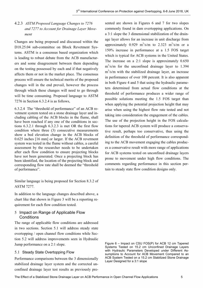
Performance comparisons between the 3 dimensionally stabilized drainage layer system and the corrected un-confined drainage layer test results as previously pre-
sented are shown in Figures 6 and 7 for two slopes commonly found in dam overtopping applications. On a 3:1 slope the 3 dimensional stabilization of the drain-age layer allows for an increase in unit discharge from approximately 0.929 m3/s/m to 2.323 m3/s/m or a 150% increase in performance at a 1.5 FOS target which is typical for ACB systems in the United States. The increase on a 2:1 slope is approximately 0.650 m3/s/m for the unconfined drainage layer to 1.394 m3/s/m with the stabilized drainage layer, an increase in performance of over 100 percent. It is also apparent in both Figure 4 and 5 that using the hydraulic parame-ters determined from actual flow conditions at the threshold of performance produces a wider range of possible solutions meeting the 1.5 FOS target than when applying the potential projection height that may arise when using the highest flow rate tested and not taking into consideration the engagement of the cables. The use of the projection height in the FOS calcula-tions for tapered ACB system will produce a conserva-tive result, perhaps too conservative, thus using the definition of the threshold of performance correspond-ing to the ACB movement engaging the cables produc-es a conservative result with more range of applications for ACB systems tested on unconfined drainage layers prone to movement under high flow conditions. The comments regarding performance in this section per-tain to steady state flow condition designs only.
Figure 6 – Impact on CSU FOS(P) for ACB 12 cm Tapered Systems Tested on 15.2 cm Unconfined Drainage Layers with Hydraulic Parameters Developed under Different As-sumptions to Account for ACB Movement Compared to an ACB System Tested on a 15.2 cm Stabilized Stone Drainage Layer Designed for a 3:1 slope

3rd International Conference on Protection against Overtopping, 6-8 June 2018, UK
The Effect of a Stabilized Stone Drainage Layer on ACB Performance in Open Channel Flow Applications 6
Figure 7 – Impact on CSU FOS(P) for ACB 12 cm Tapered Systems Tested on 15.2 cm Unconfined Drainage Layers with Hydraulic Parameters Developed under Different As-sumptions to Account for ACB Movement Compared to an ACB System Tested on a 15.2 cm Stabilized Stone Drainage Layer Designed for a 2:1 slope
5.2 Hydraulic Jump Conditions
Hydraulic Jump performance has been an elusive yet critical component of ACB performance in high veloci-ty dam overtopping and emergency spillway applica-tions. The first recorded testing of hydraulic jump sta-bility of an ACB system was in 2006 conducted at CSU in Fort Collins for Armortec (Thornton et al., 2007). This testing was conducted on an 8.8:1 slope with the ACBs (15.2 cm thick 244 kg/m2 nominal unit weight) placed on a 15.2 cm stone layer placed directly on a concrete surface (i.e. there was no soil subgrade utilized in this testing). The data generated from this first test was of limited utility as an envelope curve of Energy Ratio vs Froude Ratio was developed but was valid for slopes of 8.8:1 or flatter.
In 2010 Shoretec (Thornton et al. 2011) ran a series of hydraulic jump tests using the 30 cm tapered ACB (195 kg/m2 nominal unit weight) in a flume with a 2:1 bed slope constructed with subgrade soil, a geotextile,
a 10.2 cm unconfined stone drainage layer and a ge-ogrid layer on top of the stone. To induce the hydraulic jump a gate with a variable opening was placed in the flume 15.3 m from the top of the slope. The threshold of performance of this system was reached at a unit discharge of 0.696 m3/s/m.
Hydraulic Jump tests were also conducted on the ACB Shoretec EPEC system in 2017 on a 2:1 slope installed as shown in Figure 1. The gate was placed in the flume at the identical location as in the 2011 Shoretec hy-draulic jump testing and the ACB units were identical to those used in the 2011 test. A photograph of the 2017 hydraulic jump testing of the EPEC system is shown in Figure 8.
Figure 8 – Photo of Shoretec EPEC System Under Hydraulic Jump Test Conditions
The Shoretec EPEC ACB system withstood the maxi-mum flume discharge capacity (unit discharge of 2.579 m3/s/m) and remain stable. When compared to the pre-vious testing on a 2:1 slope and an unconfined stone drainage layer, this represents a 266% improvement in performance.

3rd International Conference on Protection against Overtopping, 6-8 June 2018, UK
The Effect of a Stabilized Stone Drainage Layer on ACB Performance in Open Channel Flow Applications 7
Hydraulic jump can be predicted with accurate hydrau-lic modeling for both location and magnitude, however there could be scenarios that develop during an over-topping event that cause a hydraulic jump such as the accumulation of debris causing a set of conditions that might induce the jump. The maximum magnitude of such an event could be estimated and compared to the hydraulic jump performance of the EPEC system as another point of analysis during the ACB design add-ing robustness to the ACB system being proposed.
Figure 9 – Comparison of Hydraulic Jump Performance Be-tween an Unconfined and a Confined Stone Drainage Layer on a 2:1 Slope
The dramatic improvements seen in hydraulic jump and steady state overtopping performance with the Shoretec EPEC system will provide for an increased range of economically beneficial and technically valid applications for ACBs in dam overtopping and emer-gency spillway applications. The data on hydraulic jump performance of ACB systems at present is empir-ical and the scientific understanding of the variables impacting performance are in their infancy. Major gains in this area of the science of hydraulic jumps and countermeasure performance will be made once a con-certed research effort is undertaken to understand hy-draulic jump from a basic science level and apply that knowledge to commercially available products.
6 3-dimensional Load Transfer Platform Installation and Design Considerations
The installation details for the load transfer platform (aka Presto Geoweb) is unique for every project and calculations and plans will need to be specifically de-veloped for each individual project as is the case with sizing the ACB blocks and the subsequent installation details. Typically, we will look at the geometry of the areas to be covered, the slope upon which the ACBs
and geoweb are to be placed, the weight of the ACB system and the length of the slope. Based on this in-formation the number of tendons and corresponding strength for each panel of geoweb are determined based upon slope length as shown in Table 2.
Table 2 – Geoweb 30V6 Components Required on 2:1 Slope
Slope Length (m)
Tendon Type
# Tendons / Panel
Clip Spac-ing
Anchor Cap (N)*
6.1 TP93 3 8 4048
9.1 TP93 3 8 5827
12.2 TP93 3 8 7829
15.2 TP93 3 8 9831
18.3 TP93 3 8 11877
21.3 TP93 4 8 10231
24.4 TP93 4 8 11743
27.4 TP93 5 8 10588
30.5 TP93 6 8 9831
38.1 TP93 8 8 9252
45.7 TP93 9 8 9831
53.3 TP93 11 8 9386
61.0 TP93 13 8 9074
∗ Per Tendon
There are more details available and industry standards upon which these calculations and installation details are developed. This information would be provided in a typical design profile and project specification but are considered to be beyond the scope of this paper.
7 Conclusions The conclusions that can be drawn from the testing conducted on the Shoretec EPEC ACB system are as follows:
1. ACB Stone movement is first noticed on a 10.2 cm thick unconfined stone drainage layer at a 1.22 m overtopping event on a 2:1 slope. Increasing the unconfined stone drainage layer thickness also in-creases the rate of onset of the ACB movement to the point where design concerns are raised if not accounted for in the flume test data analysis used to determine ACB hydraulic design parameters.
2. ACB Block movement and the subsequent associ-ated performance issues and concerns are eliminat-ed with the Shoretec EPEC (one potential means of 3 dimensionally stabilizing a stone drainage layer) system when compared to similar ACB systems tested on an unconfined stone drainage layer.
3rd International Conference on Protection against Overtopping, 6-8 June 2018, UK
The Effect of a Stabilized Stone Drainage Layer on ACB Performance in Open Channel Flow Applications 8
3. Steady state overtopping performance with the Shoretec EPEC system showed a 150% increase when applied on a 3:1 slope.
4. Hydraulic jump performance showed a 266% im-provement with the Shoretec EPEC system on a 2:1 slope.
5. Language in ASTM pertaining to the “threshold of performance” for ACB systems needs to be changed to address ACB Block movement on un-confined stone drainage layers to preserve the con-servative design practices which are the corner-stone of ACB systems.
6. Use of the 3-dimensional load platform also helps in the field installation by ensuring the correct thickness of the stone drainage layer is placed on the subgrade and also makes leveling and working on the stone drainage layer friendlier to the in-stalling contractor.
References
ASTM 7276-16 (2016) – Standard Guide for Analysis and Interpretation for Articulating Concrete Block (ACB) Revetment Systems in Open Channel Flow
ASTM 7277-16 (2016) – Standard Test Method for Perfor-mance Testing of Articulating Concrete Block (ACB) for Hydraulic Stability in Open Channel Flow
Cox, Amanda L. (2010) – Moment Stability Analysis Meth-od for Determining Safety Factors For Articulating Con-crete Blocks, PhD Dissertation Colorado State University Fort Collins Colorado June 2010
NCMA (2010) – Design Manual for Articulating Concrete Block (ACB) Revetment Systems
Thornton, Christopher I, Scholl, Bryan N., Yaw, Miles B., Youngblood, Natalie (2013) Armortec 40-T Testing Steady State Overtopping Flow Conditions
Turner, Michael D., Cox, Amanda L., Thornton, Christopher I. (2011) Shoretec SD 475-OCT Testing Steady State Overtopping Flow Conditions
Turner, Michael D., Cox, Amanda L., Thornton, Christopher I. (2011) Shoretec SD-475 OCT Testing Hydraulic Jump Flow Conditions
Thornton, Christopher I., (2018) Shoretec Testing SD-475 OCT Testing Steady State Overtopping Flow Conditions
Thornton, Christopher I. (2018) Shoretec Testing SD-475 OCT Testing Hydraulic Jump
Thornton, Christopher I., Varyu, David R., Robeson, Mi-chael D. (2007) Hydraulic Jump Data Report 2006 Test-ing for Armortec Erosion Control Solutions Inc.