The Duke Power Annual Plan November 1, 2005 page/DEC/2005 Duke...Duke Power, ("Duke Power" or "the...
104
The Duke Power Annual Plan November 1, 2005 A Duke ,,EnergVe
Transcript of The Duke Power Annual Plan November 1, 2005 page/DEC/2005 Duke...Duke Power, ("Duke Power" or "the...

The Duke Power
Annual Plan
November 1, 2005
A Duke ,,EnergVe


TABLE OF CONTENTS
EXECUTIVE SUMMARY . . . . . . . . . . . . . . . . . . . . . . . . . . . . . . . . . . . . . . . . . . . . . 3
I. INTRODUCTION. . . . . . . . . . . . . . . . . . . . . . . . . . . . . . . . . . . . . . . . . . . . . . . . . . 5
II. DUKE POWER CURRENT ST A TE . . . . . . . . . . . . . . . . . . . . . . . . . . . . . . . . . . . 5
Overview.................................................... 5
Transmission System Adequacy . . . . . . . . . . . . . . . . . . . . . . . . . . . . . . . . . . 8
Existing Generation Plants in Service . . . . . . . . . . . . . . . . . . . . . . . . . . . . . . 9
Fuel Supply . . . . . . . . . . . . . . . . . . . . . . . . . . . . . . . . . . . . . . . . . . . . . . . . . 12
Renewable Energy Initiatives . . . . . . . . . . . . . . . . . . . . . . . . . . . . . . . . . . . 12
Demand-Side Management Programs............ . . . . . . . . . . . . . . . . . 13
Curtailable Service. . . . . . . . . . . . . . . . . . . . . . . . . . . . . . . . . . . . . . . . . . . . 14
Wholesale Power Sales Commitments............................. 14
Wholesale Purchased-Power Agreements . . . . . . . . . . . . . . . . . . . . . . . . . . 15
Legislative and Regulatory Issues . . . . . . . . . . . . . . . . . . . . . . . . . . . . . . . . 17
Ill. RESOURCE NEEDS ASSESSMENT (FUTURE ST A TE). . . . . . . . . . . . . . . . . 17
Load Forecast . . . . . . . . . . . . . . . . . . . . . . . . . . . . . . . . . . . . . . . . . . . . . . . 18
Changes to Existing Resources. . . . . . . . . . . . . . . . . . . . . . . . . . . . . . . . . . . 21
(PP Contract Expirations & Retirements)
Reserve Margin Explanation and Justification. . . . . . . . . . . . . . . . . . . . . . . 22
Load and Resource Balance . . . . . . . . . . . . . . . . . . . . . . . . . . . . . . . . . . . . . 24
IV. RESOURCE ALTERNATIVES TO MEED FUTURE ENERGY NEEDS..... 28
V. OVERALL PLANNING PROCESS CONCLUSIONS . . . . . . . . . . . . . . . . . . . . 28
APPENDICES . . . . . . . . . . . . . . . . . . . . . . . . . . . . . . . . . . . . . . . . . . . . . . . . . . . . . . 30
Appendix A: Quantitative Analysis . . . . . . . . . . . . . . . . . . . . . . . . . . . . . . . 31
Appendix B: Cross Reference Table
for Annual Plan Regulatory Requirements . . . . . . . . . . . . . . . . . . . . 53
Appendix C: 2005 FERC Form 715.............. . . . . . . . . . . . . . . . . . 55
Appendix D: Curtailable Service & Demand-Side Management Data. . . . 56

Appendix E: Seasonal Projection of Load, Capacity & Reserves . . . . . . . . 63
Appendix F: Generating Units Under Construction Or Planned. . . . . . . . . 67
Appendix G: Proposed Generating Units At Locations Not Known. . . . . . 68
Appendix H: Transmission Lines And Other Associated Facilities
Planned Or Under Construction. . . . . . . . . . . . . . . . . . . . . . . . . . . . 69
Appendix I: Generation And Associated Transmission Facilities
Subject To Construction Delays.......... . . . . . . . . . . . . . . . . . 71
Appendix J: Demand-Side & Supply-Side Options Referenced In The Plan 72
Appendix K: Non-Utility Generation/Customer-Owned Generation/
Stand-by Generation . . . . . . . . . . . . . . . . . . . . . . . . . . . . . . . . . . . 78
Appendix L: 2004 FERC Form 1 pages. . . . . . . . . . . . . . . . . . . . . . . . . . . . . 86
Appendix M: Other Information ( economic development). . . . . . . . . . . . . . 95
Appendix N: Legislative and Regulatory Issues . . . . . . . . . . . . . . . . . . . . . . 96
2

, )
EXECUTIVE SUMMARY
Duke Power, ("Duke Power" or "the Company"), a division of Duke Energy Corp., is responsible for meeting its customers' energy needs in a reliable, economical manner with a least-cost mix of generation resources and demand-reduction measures. For the past 10 to 15 years, the addition of low-cost peaking generation capacity was sufficient to meet incremental near-term needs. Now, however, Duke Power faces a potential need over the next decade for additional intermediate and baseload resources to meet the growing demand for electricity.
Based on preliminary analysis from last year, the Company issued a request for proposals (RFP) for peaking and intermediate capacity. Duke Power filed preliminary information with the North Carolina Utilities Commission (NCUC) pertaining to Certificates of Public Convenience and Necessity for up to 1600 MWs of new coal generation and 600 MWs of combined-cycle generation. In addition, the Company announced its intention to prepare a cost estimate for a combined construction and operating license for a new nuclear plant. The 2005 Annual Plan process focused on verifying and refining the results of the preliminary analysis to determine appropriate next steps.
Consistent with the responsibility to meet customer energy needs in a reliable, economical manner, the Company's resource planning approach includes both quantitative analysis and qualitative considerations. A quantitative analysis can provide insights on future risks and unce1iainties associated with fuel prices, load growth rates, capital and operating costs and other variables; however it does not reflect state or national public policy trends or goals related to the energy industry. Additional perspectives such as the state of competitive markets, the impo1iance of fuel diversity, the Company's environmental profile, the stage of technology deployment and regional economic development are also important factors to consider as long-term decisions are made regarding new generation.
Company management uses all of these perspectives and analysis to ensure that Duke Power will meet near-term and long-tenn load obligations, while maintaining future flexibility to adjust to changing operating circumstances.
Planning Process Results
The Fall 2005 Forecast indicates that Duke Power has sufficient resources to meet customer demand through the end of 2006. Beginning in 2007, approximately 330 MW of additional capacity will be needed to meet planning target reserve margins. The need grows to approximately 3400 MW by 2011 and 7400 MW by 2020. The factors that influence this are:
• Future load growth projections • Reduction of available capacity and energy (resources), and • A 1 7 percent target planning reserve margin over the 15 year horizon.
3

The quantitative analysis suggests that a combination of additional baseload, intermediate and peaking generation and demand-side management (DSM) programs are required over the next fifteen years. New coal and nuclear capacity additions, complemented by natural gas combustion turbine and combined-cycle units, are attractive supply-side options under a variety of sensitivities and scenarios. In light of this analysis, as well as the public policy debate on energy and environmental issues and the state of competitive markets, Duke Power has developed a strategy to ensure that the Company can reliably meet customers' energy needs while maintaining flexibility pertaining to long-term generation decisions.
The Company will take the following actions in the upcoming year:
• Complete the RFP process to evaluate potential peaking and intermediate generation opportunities in the wholesale market.
• Continue to evaluate new nuclear generation by pursuing the Nuclear Regulato1y Commission's Combined Construction and Operating License, with the objective of potentially bringing a new plant on line by 2016.
• Continue to evaluate new coal generation, with the objective of potentially bringing additional capacity on line by 2011.
• Continue to evaluate coal and natural gas prices. • Maintain the option to license and permit a new combined-cycle facility. • Continue DSM program design and implementation. • Complete an evaluation ofrenewable teclmologies.
4

I. INTRODUCTION
Duke Power has an obligation to provide reliable, economical electric service to its customers in North Carolina and South Carolina. To meet this obligation, the Company conducted a resource planning process that serves as the basis for its 2005 Annual Plan.
This 2005 Annual Plan will discuss:
• Duke Power's current state, including existing generation, demand and purchased power agreements
• The 15-year load forecast and resource need projection • The target planning reserve margin • New generation, demand-side and purchased-power opportunities • The results of the planning process, and • Near-term actions needed to meet customers' energy needs that maintains
flexibility if operating environments change.
II. DUKE POWER CURRENT STATE
Overview
Duke Power is one of the largest investor-owned utilities in the United States, with an approximately 22,000-square-mile service area in central and western North Carolina and western South Carolina. In addition to retail sales to approximately 2.23 million customers, Duke Power also sells wholesale electricity to incorporated municipalities and to public and private utilities. The tables below show numbers of customers and sales of electricity by customer groupings.
Table 2.1 Retail Customers (1000s, by number billed)
Residential General Service Industrial Nantahala Power & Light Other
Total
2004 1,841 306
8 67 12
2,234
2003 1,814
300 8
66 11
2,199
(Number of customers is average of monthly figures)
5
2002 1,782
293 8
64 11
2,158

i
Table 2.2 Electricity Sales (GWH Sold - Years Ended December 31)
Electric Operations 2004 2003 2002 Residential 24,542 23,356 23,898 General Service 24,775 23,933 23,831 Industrial 25,085 24,645 26,141 Nantahala Power & Light 1,995 1,898 1,787 Othera 267 268 269
Total Retail Sales 76,664 74,100 75,926 Wholesale Salesb 2,037 2,359 2,048
Total GWH sold 78,701 76,459 77,974
'Other= Municipal street lighting and traffic signals b Wholesale sales include sales to Schedule 1 QA customers. Western Carolina University, City of Highlands and Catawba Owners. Shm1-term, non-firm wholesale sales subject to the 8PM sharing agreement are not included.
Duke Power meets energy demand in part by purchases from the open market, through longer-term purchased power contracts and from the following electric generation assets:
• Three nuclear generating stations with a combined net capacity of 6,996 MW (including all of Catawba Nuclear Station)
• Eight coal-fired stations with a combined capacity of7,754 MW • 31 hydroelectric stations (including two pumped-storage facilities) with a
combined capacity of3,169 MW, and • Seven combustion turbine stations with a combined capacity of 2,447 MW.
Duke Power's power delivery system consists of approximately 94,000 miles of distribution lines and 13,000 miles of transmission lines. The transmission system is directly connected to all the utilities that surround the Duke Power service area. There are 22 interconnections with eight different utilities - Progress Energy Carolinas, American Electric Power, Tennessee Valley Authority, Southern Company, Yadkin, Southeastern Power Administration (SEP A), South Carolina Electric and Gas and Santee Cooper (also known as South Carolina Public Service Authority). These interconnections allow utilities to work together to provide an additional level of reliability. The strength of the system is also reinforced through coordination with other electric service providers in the Virginia-Carolinas (V ACAR) subregion, Southeastern Electric Reliability Council (SERC) and North American Electric Reliability Council (NERC).
The following map provides a high-level view of the Duke Power system.
6

Duke Power Generating System
.. NUCLEAR @) FOSSIL
0
• HYDRO ~ RIVERS
COUNTIES
CITIES
c::::::::J SERVICE AREA
STATE LINE
HIGHWAY
..••. . •.. . .Virginia . .• ,······· ····.• Tennessee { -- --------·--· ----- -
A Duke ,,Power®

Transmission System Adequacy 1
Duke Power monitors the adequacy and reliability of its transmission system and interconnections through internal analysis and patiicipation in regional reliability groups. Internal transmission planning looks ahead 10 years at available generating resources and projected load to identify transmission system upgrade and expansion requirements. Corrective actions are planned and implemented in advance to ensure continued costeffective and high-quality service. Regional reliability groups also use Duke Power's transmission model data in their analyses.
The Company monitors transmission system reliability by evaluating changes in load, generating capacity, transactions and topography. A detailed annual screening ensures compliance with Duke Power's Transmission Planning Guidelines for voltage and thermal loading, using screening methods that comply with SERC policy and NERC Reliability Standards. The screening results identify the need for future transmission system expansion and upgrades and are used as inputs into the Duke Power Transmission Asset Management Plan (TAMP). The TAMP process evaluates problem-solution alternatives and their priority, scope, cost, and timing. The result of the TAMP process is a budget and schedule of transmission system projects.
Duke Power evaluates all transmission reservation requests for impact on transfer capability and compliance with the Company's Transmission Planning Guidelines. Studies are performed to ensure transfer capability is acceptable and exceeds V ACAR Reserve Sharing Agreement requirements. The V ACAR Reserve Sharing Agreement ensures that all V ACAR member control areas have sufficient generation to meet their largest single generation contingency. The TAMP process is also used to manage projects for improvement of transfer capability.
Lessons learned from the August 2003 blackout in the northeast United States have been incorporated into Duke Power's processes. Operators now have additional monitoring tools and training to enhance their ability to recognize deteriorating system conditions. Refined procedures have also been developed in the event a black stati is required to restore the system.
SERC audits Duke Power every three years for compliance with NERC Reliability Standards. Specifically, the audit requires Duke Power to demonstrate that its
1 NCUC Order dated Februaiy 22, 2005 in Docket No. E-100, Sub 102 requires utilities to address transmission system adequacy in annual plans and to provide FERC Form 715. Appendix C to this Annual Plan includes a copy of Duke Power's most recent FERC Form 715 with attachments and exhibits. Duke Power's FERC Fo1111 715 is confidential pursuant to N.C. Gen. Stat. § 132-1.2, and Appendix C is filed under seal as specified in NCUC Rule RS-60.
8

transmission planning practices meet NERC standards and to provide data supporting the Company's annual compliance filing certifications.
Duke Power patiicipates in a number of regional reliability groups to coordinate analysis ofregional, sub-regional and inter-control area transfer capability and interconnection reliability. The reliability groups:
• Assess the interconnected system's capability to handle large firm and non-firm transactions
• Ensure that planned future transmission system improvements do not adversely affect neighboring systems, and
• Ensure the interconnected system's compliance with NERC Reliability Standards.
Regional reliability groups evaluate transfer capability and compliance with NERC Reliability Standards for the upcoming peak season and five and ten-year periods. The groups also perform computer simulation tests for high transfer levels to verify satisfactory transfer capability.
The Company serves as Reliability Coordinator for the V ACAR sub-region. NERC conducted a readiness assessment of Duke Power's Reliability Coordinator function in June 2005 and found that V ACAR has adequate facilities, processes and procedures to perform its Reliability Coordinator functions. NERC also determined that the staff is knowledgeable and competent, and identified several "Examples of Excellence" during the assessment.
Existing Generation Plants in Service
Duke Power's generation portfolio is a balanced mix of resources with different operating and fuel characteristics. This mix is designed to provide energy at the lowest reasonable cost to meet the Company's obligation to serve customers. Duke Powerowned generation, as well as purchased power, is evaluated on a real-time basis in order to select and dispatch the lowest-cost resources to meet system load requirements. In 2004, Duke Power's nuclear ( 45.9%) and coal-fired generating units (52.2%) met the vast majority of customer needs. Hydroelectric and combustion-turbine generation and economical purchases from the wholesale market supplied the remainder.
The tables below list the Duke Power plants in service in Notih Carolina and South Carolina with plant statistics, and the system's total generating capability.
9

Table 2.3 North Carolina a,b,c,d
NAME UNITS SUMMER WINTER LOCATION PLANT CAPACITY CAPACITY TYPE MW MW
Allen 1-5 1145.0 1179.0 Belmont, N.C. Conventional Coal
Belews Creek 1-2 2270.0 2320.0 Belews Creek, Conventional N.C. Coal
Buck 3-6 369.0 377.0 Salisbury, Conventional N.C. Coal
Cliffside 1-5 760.0 770.0 Cliffside, N.C. Conventional Coal
Dan River 1-3 276.0 283.0 Eden, N.C. Conventional Coal
Marshall 1-4 2110.0 2110.0 Terrell, N.C. Conventional Coal
Riverbend 4-7 454.0 464.0 Mt. Holly, Conventional N.C. Coal
TOTALN.C. 7384.0MW 7503.0MW CONVENTIONAL COAL Buck 7C-9C 93.0 93.0 Salisbury, Combustion
N.C. Turbine ) Dan River 4C-6C 85.0 85.0 Eden, N.C. Combustion
Turbine Lincoln 1 - 16 1268.0 1488.0 Stanley, N.C. Combustion
Turbine Riverbend 8C-11C 120.0 120.0 Mt. Holly, Combustion
N.C. Turbine TOTALN.C. 1566.0 MW 1786.0MW COMB. TURBINE
McGuire 1-2 2200.0 2312.0 Huntersville, Nuclear N.C.
TOTALN.C. 2200.0 MW 2312.0MW NUCLEAR
N.C. Hydro Units 613.7 MW 613.7 MW 18 N.C. Hydro Hydro Stations
TOTALN.C. 11,763.7 MW 12,214.7MW CAPABILITY
10

• . )
Table 2.4 South Carolina a,b,c,d
NAME UNIT SUMMER WINTER LOCATION PLANT # CAPACITY CAPACITY TYPE
MW MW Lee 1-3 370.0 372.0 Pelzer, S.C. Conventional
Coal TOTALS.C. 370.0 MW 372.0MW CONVENTIONAL COAL
Buzzard Roost 6C-15C 196.0 196.0 Chappels, S.C. Combustion Turbine
Lee 4C-6C 90.0 90.0 Pelzer, S.C. Combustion Turbine
Mill Creek 1-8 595.0 739.0 Blacksburg, Combustion s.c. Turbine
TOTALS.C. 881.0MW 1025.0 MW COMB TURBINE
Catawba 1-2 2258.0 2326.0 York, S.C. Nuclear Oconee 1-3 2538.0 2592.0 Seneca, S.C. Nuclear TOTALS.C. 4796.0 MW 4918.0MW NUCLEAR
Jocassee 1-4 680.0 680.0 Salem, S.C. Pumped Storage
Bad Creek 1-4 1360.0 1360.0 Salem, S.C. Pumped Storage
TOTAL PUMPED 2040.0MW 2040.0MW STORAGE S.C. Hydro Units 515.2 MW 515.2 MW 11 S.C. Hydro Hydro
Stations TOTALS.C. 8602.2MW 8870.2MW CAPABILITY
Table 2.5 Total Generation Capability a,b,c,d
NAME SUMMER WINTER CAP A CITY CAPACITY MW MW
TOTAL DUKE GENERATING 20,366 21,085 CAPABILITY
Note a: Unit information is provided by state, but resources are dispatched on a system-wide basis.
Note b: Summer and winter capability does not take into account reductions due to environmental
II

\
emission controls.
Note c: Catawba Units 1 and 2 capacity reflects 100% of the station's capability, and does not factor in the No11h Carolina Municipal Power Agency #1 's (NCMPA#l) decision to sell or utilize its 832 MW retained ownership in Catawba.
Noted: The Catawba units' multiple owners and their effective ownership percentages are:
CATAWBA OWNER PERCENT OF OWNERSHIP Duke Power 12.5% North Carolina Electric 28.125% Membership Corporation (NCEMC) NCMPA#l 37.5% Piedmont Municipal Power 12.5% Agencv (PMPA) Saluda River (SR) 9.375%
Fuel Supply
Duke Power burns approximately 18 million tons of coal annually. Coal is procured primarily from Central Appalachian coal mines and delivered by Norfolk Southern or CSX railroads. The Company assesses coal market conditions to determine the appropriate mix of contract and spot purchases, in order to reduce the Company's exposure to the risk of price fluctuations. The Company may increase its diversity of coal supply as a result of the February 2005 RFP that will provide the ability to evaluate coal supply from throughout the United States and international sources.
To provide fuel for Duke Power's nuclear fleet, the Company maintains a diversified portfolio of natural uranium and downstream services ( conversion, emichment and fabrication) supply contracts from around the world. The majority of the energy production from Duke Power generating units has come from the coal and nuclear units (98%). Hence, the recent increases in natural gas and oil prices have had less impact on Duke Power's cost to produce energy than utilities who are more dependent upon oil and natural gas.
Renewable Energy Initiatives
Duke Power has supported development of renewable energy through:
• Financial and in-kind support of the North Carolina GreenPower program (a voluntary program that promotes the development of renewable generation resources)
• Development of a Small Customer Generator Rider, and • Existing contracts with Qualifying Facilities.
The North Carolina GreenPower Program is a statewide initiative approved by the NCUC. The mission of NC GreenPower is to encourage renewable generation
12

)
development from resources such as sun, wind, hydro and organic matter by enabling North Carolina electric consumers, businesses, and organizations to help offset the cost to produce green energy. Duke Power supports NC GreenPower by facilitating customer contributions to the program. The Company has also made direct financial contributions to the program.
Duke Power, other utilities and stakeholders worked collaboratively to develop Model Small Generator Interconnection Standards. These standards provide potential owners of small distributed generation systems, including renewable energy sources, with uniform, simplified standard criteria and procedures for interconnecting with electric utilities in North Carolina. Duke Power has filed with the NCUC, for approval, a Small Customer Generator Rider that incorporates this standardization.
Duke Power currently has purchased-power agreements with the following Qualifying Facility renewable energy providers:
• Salem Energy Systems, the Hanes Road Landfill in Winston-Salem - 3 MW • Catawba County Blackburn Landfill facility - 3 MW • No1ihbrook Carolina Hydro (5 facilities) - 6 MW • Town of Lake Lure Hydro - 2 MW • 19 hydro energy providers - 5 MW total *
* See Appendix K for further details on the 19 hydro energy providers.
Demand-Side Management (DSM) Programs
Duke Power uses DSM programs to help manage customer demand in an efficient, costeffective manner. DSM programs can vary greatly in their dispatch characteristics, size and duration of load response, ce1iainty of load response and frequency of customer paiiicipation. In general, DSM programs fall into two primary categories: energy efficiency and demand response (interruptible or time of use).
Demand Response - Load Control Curtailment Programs These programs can be dispatched by the utility and have the highest level of certainty. Once a customer agrees to participate in a demand response load control curtailment program, the Company controls the timing, frequency and nature of the load response. Duke Power's load control curtailment programs include:
• Residential Air Conditioning Direct Load Control • Residential Water Heating Direct Load Control.
13

)
J
)
Demand Response - Interruptible & Time of Use Programs These programs rely either on the customer's ability to respond to a utility-initiated signal requesting curtailment or on rates with price signals that provide an economic incentive to reduce or shift load. Timing, frequency and nature of the load response depend on customers' voluntary actions. Duke Power's interruptible and time of use curtailment programs include:
• Programs using utility-requested cmtailment signal o Interruptible Power Service o Standby Generator Control
• Rates using price signals o Residential Time-of-Use o General Service and Industrial Optional Time-of-Use rates o Hourly Pricing for Incremental Load and Hourly Pricing - Flex
Energy Efficiency Programs These programs are typically 11011-dispatchable, conservation-oriented education or incentive programs. Energy and capacity savings are achieved by changing customer behavior or through the installation of more energy-efficient equipment or structures. All effects of these programs are reflected in the customer load forecast. Duke Power's existing energy efficiency programs include:
• Residential Energy Star • Residential Service Controlled Water Heating • Existing Residential Housing Program • Special Needs Energy Products Loan Program
A more detailed description of each program can be found in Appendix D.
Curtailable Service
Duke Power offers a Curtailable Service Rider (Rider CS) to customers as a pilot program. This program mitigates the Company's financial risk of being forced, by capacity problems, to purchase power to supply native load during times of very high wholesale prices. Payments are closely aligned with market prices of energy, allowing the Company to offset high-cost energy purchases by paying participating customers to curtail load. This ultimately benefits all customers.
Wholesale Power Sales Commitments
Duke Power provides wholesale power sales to Western Carolina University (WCU), the city of Highlands and to customers served under Schedule lOA. These customers' load requirements are included in the Seasonal Projections of Load, Capacity and Reserves page 25. Under Intercmmection Agreements, Duke Power is obligated to backstand the load ofNCEMC and Saluda River, up to the amount of their ownership entitlement in
14

Catawba Nuclear Station. Those obligations are reflected throughout the 15-year planning horizon.
PMP A has served notice to end its Interconnection Agreements with Duke Power effective January I, 2006. With that termination, the Company no longer has an obligation to supply supplemental energy to PMPA or to backstand PMPA's load up to its ownership entitlement in the Catawba Nuclear Station.
The Rural Utilities Service (RUS) has issued a Request for Bid for the purchase of Saluda River's ownership interest in the Catawba Nuclear Station. If the sale is completed, Duke Power's obligation to provide backstand for load up to Saluda's ownership entitlement would change.
Beginning January I, 2005, two firm wholesale agreements became effective between Duke Power and NCMPAl. The first is a 75 MW capacity sale that expires 12/31/2007. The second is a backstand agreement ofup to 432 MW (depending on operation of the Catawba and McGuire facilities) that expires 12/31/2007. These are reflected on line 19 of the Seasonal Projections of Load, Capacity and Reserves Table on page 25.
[END CONFIDENTIAL]
Wholesale Purchased-Power Agreements
Duke Power is an active participant in the wholesale market for capacity. The Company has issued RFPs for purchased-power capacity over the past several years, and has entered into purchased-power arrangements for over 2,000 MWs over the past 10 years. In addition, Duke Power has contracts with a number of Qualifying Facilities. The table below shows both the purchased power capacity obtained through RFPs as well as the larger Qualifying Facility agreements. See Appendix K for additional information on all purchases from Qualifying Facilities.
15

Table 2.6 Wholesale Purchased-Power Commitments
SUPPLIER CITY STATE SUMMER WINTER CONTRACT CONTRACT FIRM FIRNI START EXPIRATION CAPACITY CAPACITY (MW) (MW)
Rowan County Salisbury N.C. 152 185 6/1/02 5/31/07 Power, LLC Unit 1 Progress Salisbury N.C. 153 185 6/1/07 12/31/10 Ventures, Inc. Unit 1 Rowan County Salisbury N.C. 151 184 6/1/01 12/31/05 Power, LLC Unit 2 Progress Salisbury N.C. 153 184 1/1/06 12/31/10 Ventures, Inc. Unit 2 Progress Salisbury N.C. 153 185 6/1/04 5/31/08 Ventures, Inc. Unit 3
) Progress Salisbury N.C. 153 185 6/1/08 12/31/10 ) Ventures, Inc.
Unit 3 Rockingham Wentworth N.C. 160 160 1/1/06 12/31/10 Power, LLC Cherokee Gaffney s.c. 88 95 7/1/96 6/30/13 County Co generation Paiiners, L.P. Catawba Countv Newton N.C. 0 0 8/23/99 8/22/14 .) .)
Salem Energy Winston- N.C. 3 0 7/10/96 7/10/11 .)
Svstems, LLC Salem Ecusta Business Brevard N.C. 0 0 4/15/2004 4/14/2009 .) .)
Development Center Northbrook Various Both 6 6 12/4/96 12/4/06 Carolina Hydro, LLC Town of Lake Lake Lure N.C. 2 2 2/18/99 2/17/06 Lure Misc. Small Various Both 5 5 Various Assumed Hvdro Evergreen
16

\ .
)
)
Summary of Wholesale Purchased Power Commitments (as of January 1, 2006)
Total Non-Utility Generation Duke Power allocation of SEPA capacity Total Firm Purchases
Legislative and Regulatory Issues
WINTER 05/06 831 MW
19MW 850MW
SUMMER06 726MW
19MW 745MW
Duke Power is subject to the jurisdiction of many federal agencies, including FERC and EPA, as well as state commissions and agencies. The Company can also be affected by public policy actions that states and the federal government may take. For example, Duke Power is currently implementing the North Carolina Clean Smokestacks Act to reduce sulfur dioxide (SO2) and nitrogen oxide (NOx) emissions from its generation facilities, and will also have to comply with the newly issued federal rules (Clean Air Interstate Rule and Clean Air Mercury Rule) to reduce SO2, NOx and mercury emissions.
In addition, policy debate has increased on the issue of global climate change at both the state and federal levels. There is a significant amount of uncertainty regarding future federal climate change policy, and meanwhile a patchwork of state approaches is emerging. These issues, as well as the development of competitive markets and other regulato1y matters, (See Appendix N for further discussion) could have an impact on new generation decisions.
III. RESOURCE NEEDS ASSESSMENT (FUTURE STATE)
To meet the future needs of our customers, it is necessaiy to understand the load and resource balance. For each year of the planning horizon, Duke Power develops a load forecast of energy sales and peak demand. To determine total resources needed, the Company considers the load obligation plus a 17 percent target planning reserve margin. The capability of existing resources, including generating units, demand-side management programs and purchased-power contracts, are measured against the total resource need. Any deficit in future years will be met by a mix of additional resources that reliably and cost-effectively meet the load obligation.
The following sections provide detail on the load forecast and the changes to existing resources.
17

)
. J
Load Forecast
The Fall 2005 Forecast includes projections for meeting the energy needs of new and existing customers in Duke Power's service territory. Certain wholesale customers have the option of obtaining all or a portion of their future energy needs from other suppliers. While this may reduce Duke Power's obligation to serve those customers, Duke Power assumes for planning purposes that its existing wholesale customer load ( excluding Catawba owner loads as discussed below) will remain pmi of the load obligation.
The forecasts for 2005 through 2020 include the energy needs of the following customer classes: • Duke Power retail • Nantahala Power & Light (NP&L) retail • Duke Power wholesale customers under Schedule 1 0A • NP&L wholesale customers Western Carolina University and the Town of Highlands • NCEMC load relating to ownership of Catawba
In addition, the forecast includes: • Load equating to the portion of Catawba ownership related to PMP A and the Saluda
River Electric Cooperative Inc. (SR), as well as PMPA's supplemental requirements above its ownership in 2005
• [BEGIN CONFIDENTIAL]
Notes (c), (e) and (f) on pages 20 - 21 give additional detail on how the four Catawba Joint Owners were considered in the forecasts.
The current 15-year forecast reflects a 1.8 percent average annual growth in summer peak demand, while winter peaks are forecasted to grow at an average annual rate of 0.8 percent. The forecast for average annual territorial energy need is 1. 7 percent. The growth rates use 2005 as the base year with a 17,497 MW summer peak, a 16,315 MW winter peak and a 93,099 GWH average annual territorial energy need.
Duke Power retail sales have grown at an average annual rate of 1.8 percent from 1989 to 2004. (Retail sales, including line losses, are approximately 86 percent of the total energy considered in the 2005 Annual Plan.) This 15-year period of history reflects 10 years of strong load growth from 1989 to 1999 followed by five years of very little growth from 1999 to 2004. The following table shows historical and projected major customer class growth rates.
18
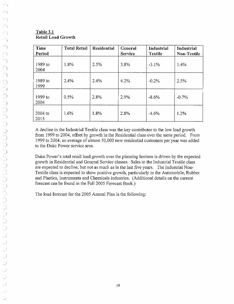
Table 3.1 Retail Load Growth
Time Total Retail Residential General Industrial Industrial Period Service Textile Non-Textile
1989 to 1.8% 2.5% 3.8% -3.1% 1.4% 2004
1989 to 2.4% 2.4% 4.2% -0.2% 2.5% 1999
1999 to 0.5% 2.8% 2.9% -8.6% -0.7% 2004
2004 to 1.6% 1.8% 2.8% -4.6% 1.2% 2015
A decline in the Industrial Textile class was the key contributor to the low load growth from 1999 to 2004, offset by growth in the Residential class over the same period. From 1999 to 2004, an average of almost 50,000 new residential customers per year was added to the Duke Power service area.
Duke Power's total retail load growth over the planning horizon is driven by the expected growth in Residential and General Service classes. Sales to the Industrial Textile class are expected to decline, but not as much as in the last five years. The Industrial NonTextile class is expected to show positive growth, particularly in the Automobile, Rubber and Plastics, Instruments and Chemicals industries. (Additional details on the current forecast can be found in the Fall 2005 Forecast Book.)
The load forecast for the 2005 Annual Plan is the following:
19

Table 3.2 Load Forecast
YEARa,b,c,d,c,f
2006 2007 2008 2009 2010 2011 2012 2013 2014 2015 2016 2017 2018 2019 2020
SUMMER (MWf 17,376 17,918 18,236 18,343 18,635 19,689 20,026 20,393 20,727 21,062 21,413 21,771 22,140 22,505 22,870
WINTER TERRITORIAL (MW)g ENERGY <GWH)g 15,425 92,333 15,815 94,865 15,934 96,348 15,878 95,789 16,001 97,479 16,936 102,556 17,119 104,388 17,301 106,208 17,497 107,973 17,602 109,745 17,758 111,662 17,957 113,629 18,116 115,625 18,273 117,636 18,381 119,707
Note a: The MW (demand) forecasts above are the same as those shown on page 29 of the Fall 2005 Forecast Book, but the peak forecasts vary from those shown on pages 24-27 of the Forecast Book, primarily because Fall 2005 Forecast Book's peak forecasts include the total resource needs for all Catawba Joint Owners and do not include the total resource needs ofNP&L.
Note b: The impact of energy efficiency DSM programs is accounted for in the load forecast.
Note c: As pai1 of the joint ownership arrangement for Catawba Nuclear Station, NCEMC and SR took sole responsibility for their supplemental load requirements beginning January I, 200 I. As a result, SR's supplemental load requirements above its ownership interest in Catawba are not reflected in the forecast. Beginning in 2009, the SR ownership po11ion of Catawba will not be reflected in the forecast due to a future sale of this interest, which will cause SR to become a full-requirements customers of another utility. SR has indicated that it will exercise the threeyear notice to terminate the Interconnection Agreement (which includes provisions for reserves) this fall, which would result in termination at the end of September, 2008.
Noted: [BEGIN CONFIDENTIAL] [END
CONFIDENTIAL]
Note e: As part of the joint ownership arrangement for the Catawba Nuclear Station, the NCMPAI took sole responsibility for its supplemental load requirements beginning January I, 2001. As a result, NCMPAI supplemental load requirements above its ownership interest in Catawba Nuclear Station are not reflected in the forecast. In 2002, NCMPAI entered into a firmcapacity sale beginning January I, 2003, when it sold 400 MW of its ownership interest in Catawba. In 2003, NCMPAI entered into another agreement beginning January 2004, when it chose not to buy reserves for its remaining ownership interest (432 MW) from Duke Power. These changes reduce the Duke Power load forecast by the forecasted NCMPA I load in the control area (988 MW at 2005 summer peak) and the available capacity to meet the load
20

, )
obligation by its Catawba ownership (832 MW). The Plan assumes that the reductions remain over the 15-year planning horizon.
Note f: The PMPA has given notice that it will be solely responsible for its supplemental load requirements beginning January I, 2006. Therefore, PMPA supplemental load requirements above its ownership interest in Catawba Nuclear Station are not reflected in the load forecast beginning in 2006. Neither will the PMPA ownership interest in Catawba be included in the load forecast beginning in 2006, because PMPA provided notice to terminate its existing Interconnection Agreement with Duke Power effective January I, 2006. Therefore, Duke Power will not be responsible for providing reserves for the PMPA ownership interest in Catawba after that date. These changes reduce the Duke Power load forecast by the forecasted PMPA load in the control area (456 MW at 2005 summer peak) and the available capacity to meet the load obligation by its Catawba ownership (277 MW). The Plan assumes that the reductions remain over the 15-year planning horizon.
Note g: Summer peak demand, winter peak demand and territorial energy are for the calendar years indicated. (The customer classes are described at the beginning of this section.) Territorial energy includes losses and unbilled sales (adjustments made to create calendar billed sales from billing period sales).
Changes to Existing Resources
Duke Power will adjust the capabilities of its resource mix over the 15-year planning horizon. Retirements of generating units, system capacity uprates and derates, purchased-power contract expiration, and adjustments in DSM capability affect the amount of resources Duke Power will have to meet its load obligation. Below are the known or anticipated changes and their impacts on the resource mix.
Purchased-Power Contract Expirations Duke Power has secured various purchased-power contracts with power marketers Progress Ventures Inc. and Rockingham Power that are currently in effect or will begin over the next three years. In 2006, the overall capability of the purchased-power contracts is approximately 618 MW. The capability in megawatts varies depending on the contract start times, their duration and capability of each contract. All contracts will expire by Dec. 31, 2010. For details, see Table 2.6, Wholesale Purchased Power Commitments, on page 16 Duke Power is currently conducting an RFP process to evaluate new intermediate and peaking resource options available beginning in 2007.
Generating Units Projected To Be Retired Various factors have an impact on decisions to retire existing generating units. These factors, including the investment requirements necessary to support ongoing operation of generation facilities, a.re continuously evaluated as future resource needs are considered. The following table reflects current assessments of generating units with identified decision dates for retirement or major refurbishment. The conditions of the units are evaluated annually and decision dates are revised as appropriate.
21

( )
Table 3.3 Projected Unit Retirements
STATION CAPACITY LOCATION DECISION PLANT TYPE INMW DATE
Buzzard Roost Hydro" 7 Channels, S.C. 6/30/2006 Conventional Hvdro Buzzard Roost 6C 22 Channels, S.C. 6/30/2008 Combustion Turbine Buzzard Roost 7C 22 Channels, S.C. 6/30/2008 Combustion Turbine Buzzard Roost 8C 22 Channels, S.C. 6/30/2008 Combustion Turbine Buzzard Roost 9C 22 Channels, S.C. 6/30/2008 Combustion Turbine Buzzard Roost l0C 18 Channels, S.C. 6/30/2010 Combustion Turbine Buzzard Roost 11 C 18 Channels, S.C. 6/30/2010 Combustion Turbine Buzzard Roost 12C 18 Channels, S.C. 6/30/2010 Combustion Turbine Buzzard Roost 13 C 18 Channels, S.C. 6/30/2010 Combustion Turbine Buzzard Roost 14C 18 Channels, S.C. 6/30/2010 Combustion Turbine Buzzard Roost 15C 18 Channels, S.C. 6/30/2010 Combustion Turbine Riverbend 8C 30 Mt. Hollv, N.C. 12/31/2010 Combustion Turbine Riverbend 9C 30 Mt. Hollv, N.C. 12/31/2010 Combustion Turbine Riverbend l0C 30 Mt. Hollv, N.C. 12/31/2010 Combustion Turbine Riverbend 11 C 30 Mt. Hollv, N.C. 12/31/2010 Combustion Turbine Buck 7C 31 Snencer, N.C. 12/31/2010 Combustion Turbine Buck SC 31 Soencer, N.C. 12/31/2010 Combustion Turbine Buck 9C 31 Snencer, N.C. 12/31/2010 Combustion Turbine Dan River4C 30 Eden, N.C. 12/31/2010 Combustion Turbine Dan River SC 30 Eden, N.C. 12/31/2010 Combustion Turbine Dan River 6C 25 Eden, N.C. 12/31/2010 Combustion Turbine
Note a: Duke Power has an operating lease for the Buzzard Roost Hydro Unit which expires June 30, 2006.
Reserve Margin Explanation and Justification
Considering customer demand uncertainty, unit outages and weather extremes, reserve margins are necessaiy to help ensure the availability of adequate resources. Many factors have an impact on the appropriate levels of reserves, including existing generation performance, lead times needed to acquire or develop new resources, and product availability in the purchased-power market.
Duke Power's experience has shown that a 17 percent target plam1ing reserve margin is sufficient to provide reliable power supplies, based on the prevailing expectations of reasonable lead times for the development of new generation, siting of transmission facilities and procurement of purchased capacity. As part of the Company's process for determining its target planning reserve margins, Duke Power reviews whether the current target planning reserve margin was adequate in the prior period. From September 2003
22

through September 2005, generating reserves, defined as available Duke Power generation plus the net of firm purchases less sales, never dropped below 500 MW. Since 1997, Duke Power has had sufficient reserves to reliably meet customer load with limited need for activation of interruptible programs. The DSM Activation History in Appendix D illustrates Duke Power's limited activation of interruptible programs through the end of September 2005.
Duke Power also continually reviews its generating system capability, level of potential DSM activations, scheduled maintenance, environmental retrofit equipment and environmental compliance requirements, purchased power availability and transmission capability to assess its capability to reliably meet customer demand. The Company will continue to monitor lead times for permitting and construction of new generation and transmission facilities, to procure power in the purchased-power market and to assess its power supply planning process (reserve margins) for possible changes.
While Duke Power uses a 17% target planning reserve margin for long-term planning, it also assesses its reserve margins on a short-term basis to determine whether to pursue additional capacity in the sho1i-term power market. As each peak demand season approaches, the Company has a greater level of certainty regarding the customer load forecast and total system capability, due to greater knowledge of near-term weather conditions and generation unit availability.
Duke Power uses adjusted system capacity2, along with Interruptible DSM capability to satisfy Duke Power's NERC Reliability Standards requirements for operating and contingency reserves. Contingencies include events such as higher than expected unavailability of generating units and increased customer load due to extreme weather conditions.
2 Adjusted system capacity is calculated by adding the expected capacity of each generating unit plus firm purchased-power capacity, less firm wholesale capacity sales.
23

Load & Resource Balance
The following chart shows the existing resources and resource requirements to meet the load obligation, plus the 17 percent target planning reserve margin. Begi1ming in 2005, existing resources, consisting of existing generation, DSM, and purchased power to meet load requirements, total 20,976 MW. The load obligation plus the 17 percent target planning reserve margin is 20,587 MW, indicating sufficient resources to meet Duke Power's obligation through 2006. A need for approximately 330 MW of additional capacity begins in 2007 and grows over time due to load growth, unit capacity adjustments, unit retirements, DSM reductions and expirations of purchased-power contracts. The need grows to approximately 3,400 MW by 2011 and 7,420 MW by 2020.
Chart 3.1 Load & Resource Balance
Resource Requirements
28000 ~-------------------------------~ 27000 26000 25000 24000 23000 22000 21000 20000 19000
;J 18000 ; 17000 ~ 16000 ~ 15000
14000 13000 12000 11000 10000 9000 8000 7000 6000 5000
DSM
Additional Resources Needed to Meet Load Plus 17% Reserves
Existing Generating Resources
2005 2006 2007 2008 2009 2010 2011 2012 2013 2014 2015 2016 2017 2018 2019 2020
Year
D Existing Duke Power Generation El Existing Purchases (incl NUGs) ■ Total DSM D Additional Resources Needed I
Projected Cumulative Future Resource Additions Year 2007 2008 2009 2010 2011 2012 2013 2014 2015 2016 2017 2018 2019 202 Resource Need 330 680 1010 1440 3400 3810 4360 4850 5290 5700 6130 6570 7000 742
The fo llowing table contains the Seasonal Projections of Load Capacity and Reserves for Duke Power where the Cumulative Future Resource Additions reflects the megawatts needed to reach a 1 7% percent reserve margin.
24

Seasonal Projections of Load, Capacity, and Reserves
W ::: WINTER, S = SUMMER w s w s w s w s w s w s w s w 05/06 2006 06/07 2007 07/08 2008 08/09 2009 09/10 2010 10/11 2011 11/12 2012 12/13
Forecast 1 Duke System Peak 15,425 17,376 15,815 17,918 15,934 18,236 15,878 18,343 16,001 18,635 16,936 19,689 17,119 20,026 17,301
Cumulative System Capacity 2 GeneraUng Capacity 19,976 19,257 19,967 19,236 19,979 19,235 19,627 18,908 19,616 18,924 19,535 18,518 19,237 18,518 19,237 3 Capacity Additions 0 2 0 50 0 0 0 0 50 0 0 0 0 0 0 4 Capacity Oerates 0 0 (12) (26) (25) (25) 0 (11) (23) 0 0 0 0 0 0 5 Capacity Retirements 0 (7) 0 0 0 (88) 0 0 0 (108) (298) 0 0 0 0
6 Cumulative Generating Capacit; 19,976 19,252 19,955 19,260 19,954 19,122 19,627 18,897 19,643 18,816 19,237 18,518 19,237 18,518 19,237
7 Cumulative Purchase Contracts 850 745 842 740 842 740 842 740 839 737 326 319 323 316 212 8 Cumulative Sales Contracts 0 0 0 0 0 0 0 0 0 0 0 0 0 0 0
9 Cumulative Future Resource Addillons 0 0 0 330 330 680 680 1,010 1,010 1,440 1,440 3,400 3,400 3,810 3,810
NJ ~~
• 10 Cumulative Production Capacity- 20,826 19,997 20,797 20,330 21,126 20,542 21,149 20,647 21,492 20,993 21,003 22,237 22,960 22,644 23,259
Reserves w/o DSM 11 Generating Reserves 5,401 2,621 4,982 2,412 5,192 2,306 5,271 2,304 5,491 2,358 4,067 2,548 5.841 2,618 5,958 12 % Reserve Margin 35.0% 15.1% 31.5% 13.5% 32.6% 12.6% 33.2% 12.6% 34.3% 12.7% 24.0% 12.9% 34.1% 13.1% 34.4% 13 % Capacity Margin 25.9% 13.1% 24.0% 11.9% 24.6% 11.2% 24.9% 11.2% 25.6% 11.2% 19.4% 11.5% 25.4% 11.6% 25.6%
DSM 14 Cumulative DSM Capacity 395 766 387 776 392 792 401 821 417 808 411 794 405 780 397
Existlng DSM Capacity 395 766 387 751 380 737 374 721 367 708 361 694 355 680 347 Potential New DSM Capacity 0 0 0 25 12 55 27 100 50 100 50 100 50 100 50
15 Cumulative Equivalent Capacity- 21,221 20,763 21,184 21,106 21,518 21,334 21,550 21,468 21,909 21,801 21,414 23,031 23,365 23,424 23,656
Reserves w/OSM 16 Equivalent Reserves 5,796 3,387 5,369 3,188 5,584 3,098 5,672 3,125 5,908 3,166 4,478 3,342 6,246 3,398 6,355 17 % Reserve Margin 37.6% 19.5% 34.0% 17.8% 35.0% 17.0% 35.7% 17.0% 36.9% 17.0% 26.4% 17.0% 36.5% 17.0% 36.7% 18 % Capacity Margin 27.3% 16.3% 25.3% 15.1% 26.0% 14.5% 26.3% 14.6% 27.0% 14.5% 20.9% 14.5% 26.7% 14.5% 26.9%
Sales (8PM) 19 Equivalent Sa!es 127 127 127 127
Equivalent Reserves 5663 3254 5236 3055 5584 3098 5672 3125 5908 3166 4478 3342 6246 3398 6355 % Reserve Margin 36.5% 18.6% 33.0% 17.0% 35.0% 17.0% 35.7% 17.0% 36.9% 17.0% 26.4% 17.0% 36.5% 17.0% 36.7% % Capacity Margin 26.7% 15.7% 24.7% 14.5% 26.0% 14.5% 26.3% 14.6% 27.0% 14.5% 20.9% 14.5% 26.7% 14.5% 26.9%

Seasonal Projections of Load, Capacity, and Reserves
W ::: WINTER, S ::: SUMMER s w s w s w s w s w s w s w s 2013 13/14 2014 14115 2015 15/16 2016 16/17 2017 17/18 2018 18/19 2019 19/20 2020
Forecast 1 Duke System Peak 20,393 17,497 20,727 17,602 21,062 17,758 21,413 17,957 21,771 18,116 22,140 18,273 22,505 18,381 22,870
Cumulative System Capacity 2 Generating Capacity 18,518 19,237 18,518 19,237 18,518 19,237 18,518 19,237 18,518 19,237 18,518 19,237 18,518 19,237 18,518 3 Capacity Additions 0 0 0 0 0 0 0 0 0 0 0 0 0 0 0 4 Capacity Derates 0 0 0 0 0 0 0 0 0 0 0 0 0 0 0 5 Capacity Retirements 0 0 0 0 0 0 0 0 0 0 0 0 0 0 0
6 Cumulative Generating Capacit} 18,518 19,237 18,518 19,237 18,518 19,237 18,518 19,237 18,518 19,237 18,518 19,237 18,518 19,237 18,518
7 Cumulative Purchase Contracts 205 117 117 72 72 72 72 72 72 72 72 72 72 72 72 8 Cumulative Sales Contracts 0 0 0 0 0 0 0 0 0 0 0 0 0 0 0
9 Cumulative Future Resource Addition~ 4,360 4,360 4,850 4,850 5,290 5,290 5,700 5,700 6,130 6,130 6,570 6,570 7,000 7,000 7,420 ~
~ ru m~
m 10 Cumulative Production Capacity 23,083 23,714 23,485 24,159 23,880 24,599 24,290 25,009 24,720 25,439 25,160 25,879 25,590 26,309 26,010
Reserves w/o DSM 11 Generating Reserves 2,690 6,217 2,758 6,557 2,818 6,841 2,877 7,052 2,949 7,323 3,020 7,606 3,085 7,928 3,140 12 % Reserve Margin 13.2% 35.5% 13.3% 37.3% 13.4% 38.5% 13.4% 39.3% 13.5% 40.4% 13.6% 41.6% 13.7% 43.1% 13.7% 13 % Capacity Margin 11.7% 26.2% 11.7% 27.1% 11.8% 27.8% 11.8% 28.2% 11.9% 28.8% 12.0% 29.4% 12.1% 30.1% 12.1%
DSM 14 Cumulative DSM Capacity 768 398 763 399 759 399 755 400 752 400 747 402 749 404 751
Existing DSM Capacity 668 348 663 349 659 349 655 350 652 350 647 352 649 354 651 Potential New DSM Capacity 100 50 100 50 100 50 100 50 100 50 100 50 100 50 100
15 Cumulative Equivalent Capacity 23,851 24,112 24,248 24,558 24,639 24,998 25,045 25,409 25,472 25,839 25,907 26,281 26,339 26,713 26,761
Reserves w/DSM 16 Equivalent Reserves 3,458 6,615 3,521 6,956 3,577 7,240 3,632 7.452 3,701 7,723 3,767 8.008 3,834 8,332 3,891 17 % Reserve Margin 17.0% 37.8% 17.0% 39.5% 17.0% 40.8% 17.0% 41.5% 17.0% 42.6% 17.0% 43.8% 17.0% 45.3% 17.0% 18 % Capacity Margin 14.5% 27.4% 14.5% 28.3% 14.5% 29.0% 14.5% 29.3% 14.5% 29.9% 14.5% 30.5% 14.6% 31.2% 14.5%
Sales (BPM) 19 Equivalent Sales
Equivalent Reserves 3458 6615 3521 6956 3577 7240 3632 7452 3701 7723 3767 8008 3834 8332 3891 % Reserve Margin 17.0% 37.8% 17.0% 39.5% 17.0% 40.8% 17.0% 41.5% 17.0% 42.6% 17.0% 43.8% 17.0% 45.3% 17.0% % Capacity Margin 14.5% 27.4% 14.5% 28.3% 14.5% 29.0% 14.5% 29.3% 14.5% 29.9% 14.5% 30.5% 14.6% 31.2% 14.5%

)
ASSUMPTIONS OF LOAD, CAPACITY, AND RESERVES TABLE
The following notes are numbered lo match the line numbers on lhe SEASONAL PROJECTIONS OF LOAD, CAPACITY, AND RESERVES table. All values are MW except where shown as a Percent.
1. Planning Is done for the peak demand for the Duke System Including Nantahala. Nantahala became a division of Duke Power August 3, 1998.
2. Generating Capacity must be online by June 1 to be included ln the available capacity for the summer peak of that year. Capacity must be online by Dec 1 to be included in the available capacity for the winter peak of that year. Includes 103 MW Nanlahala hydro capacity, and total capacity for Catawba Nuclear Station less 832 MW to account for NCMPA 1 firm capacity sale to Sou1hern Energy Company. Also, on January 1, 2006, Generating Capacity reflects a 277 MW reduction to account for PMPA termination of their interconnection agreement with Duke Power. Because lhe Lee CTs serve as a redundant safe-shutdown facility for Oconee Nuclear Station and are required by the NRC for operation of Oconee, the retirement of the existing CTs at Lee in 2006 will coincide with [he addition of new CTs at Lee also in 2006 of 86 MW.
3. Capacity Additions reflect an estimated 2 MW Marshall unit double flow IP rotor upgrade and 100 MW capacity uprate at the Jocassee pumped storage facility from increased efficiency from the new runners.
4. The expected Capacity Oerates reflect the impact of parasitic loads from planned scrubber additions to various Duke fossil generating units. The units, In order of time sequence on the LCR table is Marshall 1 • 4, Belews Creek 1 & 2, Allen 1 - 3, Cliffside 5, and Allen 4 & 5.
5. The 120 MW capacity retirement in 2010 represents the projected retirement date for all CTs at Riverbend. The 88 MW capaclty retlrement in 2008 represents the projected retirement date for 4 CT's at Buzzard Roost(Wst). The 93 MW capacity retirement in 2010 represents the projected retirement date for the existing CTs at Buck. The 108 MW capacity retirement in 2010 represents the projected retirement date for 6 CT's at Buzzard Roost{GE). The 85 MW capacity retirement in 2010 represents the projected retirement date for CTs at Dan River. Duke has an operating lease for the 7 MW Buzzard Roost Hydro Unit which expires 6130/2006. On May 23, 2000, the NRC issued to Duke a renewed facility operating license for its three nuclear units at Oconee, Duke
now has the option to operate Its Oconee units for up to 20 years followlng the year 2013. Duke will evaluate on an ongoing basis the viability of operating past the year 2013. With respect to planning purposes, the Oconee capacity is still in the plan.
The Hydro facilities for which Duke has submitted an application to FERC for licence renewal are assumed to continue operation through the planning horizon.
All retirement dates are subject lo review on an ongoing basis.
7. Cumulative Purchase Contracts have several components:
A. Effective January 1, 2001, the SEPA allocation was reduced to 94 MW. This reflects self scheduling by Seneca, Greenwood, Saluda River, NCEMC, and NCMPA 1. The 94 MW reflects allocations for PMPA and Schedule 10A customers who continue to be served by Duke.
B. Piedmont Municipal Power Agency has given notlce that !twill be solely responsible for total load requirements beginning January 1, 2006. This reduces the SEPA allocation to 18 MW fn 2006, which is attributed to Schedule 10A customers who continue to be served by Duke.
C. Purchased capacity from PURPA Qualifying Facilities Includes the 88 MW Cherokee County Cogeneration Partners contract which began fn June 1998 and expires June 2013 and miscellaneous other OF projects totaling 22 MW.
D. Purchase of 151 MW from Rowan County Power, LLC, Unit 2 began June 1, 2001 and expires December 31, 2005. E. Purchase of 152 MW from Rowan County Power, LLC. Unit 1 began June 1, 2002 and expires May 31, 2007. F. Purchase of 153 MW from Rowan County Power, LLC, Unit 3 began June 1, 2004 and expires May 31, 2008. G. Purchase of 153 MW from Progress Ventures, Inc. Rowan Unit 2 begins January 1, 2006 and expires December 31, 2010. H. Purchase of 153 MW from Progress Ventures, Inc. Rowan Unit 1 begins June 1, 2007 and expires December 31, 2010. 1. Purchase of 153 MW from Progress Ventures, Inc. Rowan Unit 3 begins June 1, 2008 and expires December 31, 2010. J. Purchase ol 160 MW from Dynegy/Rockingham unit begins January 1, 2006 and expires December 31, 2010.
9. Cumulative Future Resource Needs represent a combination of new capacity resources , short/long-term capacity purchases from the wholesale market. capacity purchase options, or capability increases which are being considered. Neither the date of operation, the type of resource, nor the slze is firm. All Future Resource Needs are uncommitted and represent capacity required to maintain the target planning reserve margin.
12. Reserve margin is shown for reference only. Reserve Margin = {Cumulative Capacity-System Peak Demand)/System Peak Demand
13. Capacity margin is the industry standard term. A 14.6 percent capacity margin ls equivalent to a 17.0 percent reserve margin. Capacity Margin = (Cumulative Capacity• System Peak Demand)/Cumulative Capacity
14. Cumulative Demand Side Management capacity represents the demand-side management contribution toward meeting the load. The programs reflected in these numbers include interruptible Demand Side Management programs designed to be activated during capacity problem situations.
27

IV. RESOURCE ALTERNATIVES TO MEET FUTURE ENERGY NEEDS
Many potential resource options are available to meet future energy needs. They range from expanding existing DSM programs to developing new DSM programs to adding new generation capacity to the Duke Power system.
Following are the generation (supply-side) technologies Duke Power considered in detail throughout the planning analysis:
Conventional Technologies (technologies in common use) • 564 MW Combustion Turbine (CT) • 585 MW Combined-Cycle (CC), with and without duct firing • 400 MW Supercritical Conventional Fossil • 600 MW Supercritical Conventional Fossil • 800 MW Supercritical Conventional Fossil • 1,200 MW Supercritical Conventional Fossil • 1,600 MW Supercritical Conventional Fossil
Demonstrated Technologies (technologies with limited acceptance and not in widespread use)
• 2,234 MW Nuclear APl000 • 600 MW Integrated Gasification Combined Cycle (IGCC)
Below are the DSM programs that were considered throughout the planning process:
Demand Response Programs • Direct Load Control • Interruptible Service • Standby Generation
See Appendix J for a discussion of resources evaluated and the process used to screen the supply-side options to reach the list above.
V. OVERALL PLANNING PROCESS CONCLUSIONS
Duke Power's Resource Planning process provides a framework for the Company to assess, analyze and implement a cost-effective approach to reliably meet customers' growing energy needs. In addition to assessing qualitative factors such as fuel diversity and wholesale market structure, a quantitative assessment was conducted using a simulation model. A variety of sensitivities and scenarios were tested against a base set of inputs, allowing the Company to better understand how potentially different future operating environments such as fuel commodity price changes, environmental emission mandates and structural regulatory requirements can affect resource choices and ultimately the cost of electricity to customers. (Appendix A provides a detailed description and results of the quantitative analysis).
28

)
The quantitative analysis suggests that a combination of additional baseload, intermediate and peaking generation and demand-side management (DSM) programs are required over the next fifteen years to reliably meet customer demand. The generation resource mix consists of natural gas combustion turbine and combined-cycle units as well as coal and nuclear capacity. In nearly all the sensitivities and scenarios tested, the plan featuring 1,600 MW of new coal capacity and 2,200 MW of new nuclear capacity performed best on a present value ofrevenue requirements basis.
In light of the quantitative results, as well as consideration of qualitative issues such as the public policy debate on energy and environmental issues and the state of competitive markets, Duke Power has developed a strategy to ensure that the Company can reliably meet customers' energy needs while maintaining flexibility pertaining to long-term generation decisions. The Company will take the following actions in the upcoming year:
• Complete the RFP process to evaluate potential peaking and intermediate generation opportunities in the wholesale market.
• Continue to evaluate new nuclear generation by pursuing the Nuclear Regulatory Commission's Combined Construction and Operating License, with the objective of potentially bringing a new plant on line by 2016.
• Continue to evaluate new coal generation, with the objective of potentially bringing new capacity on line by 2011.
• Complete the RFP process to evaluate potential peaking and intermediate generation oppmiunities in the wholesale market.
• Continue to evaluate coal and natural gas prices. • Maintain the option to license and permit a new combined-cycle facility. • Continue DSM program design and implementation. • Complete an evaluation ofrenewable technologies.
29

APPENDICES
.. l
. )
. )
. l
. )
30

APPENDIX A: QUANTITATIVE ANALYSIS
This appendix provides an overview of the quantitative analysis of resource options available to meet customers' future energy needs.
Overview of Analytical Process
Assess Resource Needs
Duke Power estimates the required load and generation resource balance needed to meet future customer demands by assessing:
• Customer load forecast peak and energy - identifying future customer aggregate demands to identify system peak demands and developing the corresponding energy load shape
• Existing supply-side resources - summarizing each existing generation resource's operating characteristics including unit capability, potential operational constraints and life expectancy
• Existing demand-side resources - detailing demand-side resource program characteristics including customer participation levels, demand reduction potential and reliability
• Operating parameters - determining operational requirements including target planning reserve margins and other regulatory considerations.
Identify and Screen Resource Options for Further Consideration
Options reflect a diverse mix of technologies and fuel sources (gas, coal, nuclear and renewable) as well as near-term and long-term timing and availability. Supply-side and demand-side options are screened based on the following attributes:
• Technically feasible and commercially available in the marketplace • Compliant with all federal and state requirements • Long-run reliability • Reasonable cost parameters.
Demand-side management options should also cover multiple customer segments including residential, commercial and industrial.
Develop Theoretical Por(folio Configurations
This step begins with a nominal set of varied inputs to test the system under different market conditions. These analyses yield many different theoretical configurations of the total operating (production) and capital costs required to meet an annual 17 percent target planning reserve margin while minimizing the long-run revenue requirements to customers.
The nominal set of inputs includes:
31

)
)
• Fuel costs and availability for coal, gas, and nuclear generation • Development, operation and maintenance costs of both new and existing
generation • Compliance with current environmental regulations • Cost of capital • System operational needs for load ramping, voltageN AR support, spinning
reserve (10 to IS-minute start-up) and other requirements as a result ofVACAR / North American Electric Reliability Council (NERC) agreements
• The projected load and generation resource need, and • A menu of new supply-side and demand-side options with corresponding costs
and timing parameters.
Duke Power reviewed a number of variations to the theoretical p01ifolios to aid in the development of the po1ifolio options in the following section.
Develop Various Portfolio Options
Using the insights gleaned from developing theoretical portfolios, Duke Power creates a representative range of generation plans reflecting plant designs, lead times and environmental emissions limits.
Recognizing that different generation plans expose customers to different sources and levels of risk, a variety of portfolios is developed to assess the impact of various risk factors on the costs to serve customers. For example, in considering the possibility of a new nuclear plant, the permitting process may delay or even prevent its development. Therefore, in addition to the nominal input of a nuclear availability date, additional test po1ifolios assume a delay in nuclear plant availability as well as no availability at all.
Conduct Portfolio Analysis
Portfolio options are tested under the nominal set of inputs as well as a variety ofrisk sensitivities and scenarios, in order to understand the strengths and weaknesses of various resource configurations and evaluate the long-term costs to customers under various potential outcomes.
The following sensitivities are evaluated:
• Construction cost sensitivity High costs to construct a new coal plant High costs to construct a new nuclear plant
• Load forecast variations Increase relative to base forecast Decrease relative to base forecast
• Fuel price variability High coal prices Low coal prices High natural gas prices Low natural gas prices
32

)
•
Constant higher natural gas and coal prices Constant lower natural gas and coal prices
Carbon tax3
In addition to the above sensitivities, the following scenarios are evaluated to understand the inter-relationship of multiple assumptions changing concurrently:
• Constant higher natural gas and coal prices AND higher new coal construction costs
• Constant higher natural gas and coal prices AND higher new nuclear construction costs
• Carbon tax AND lower load than base forecast
Quantitative Analysis Results
Resource Needs
Customer load growth coupled with the expiration of purchased-power contracts results in significant resource needs to meet energy and peak demands, based on the following assumptions:
• 1. 8% average summer peak system demand growth over the next 15 years • Generation reductions of more than 600 MW due to purchased-power contract
expirations by 2011 • Generation retirements of approximately 500 MW of old fleet combustion
turbines by 20 I 1 • Approximately 122 MW of net generation reductions due to new environmental
equipment • Continued operational reliability of existing generation po1ifolio • Continued operational reliability of the existing DSM interruptible capacity (750
MW) • Using a 17 percent target planning reserve margin for the planning horizon
The chart below represents existing resources, load growth and future resource needs.
3 Despite significant uncertainty surrounding potential future climate change policy, Duke Power has incorporated climate change policy sensitivity in its resource planning process. Inclusion of this sensitivity is not intended to reflect Duke Power's or Duke Energy's expectation regarding future climate change policy.
33

Resource Requirements
28000 .------------------------------------, 27000 26000 25000 24000 23000 22000 21000 20000 19000
~ 18000 ; 17000 ~ 16000 ~ 15000
14000 13000 12000 11000 10000 9000 8000 7000 6000 -
Additional Resources Needed to
DSM
Existing Generating Resources
5000 -t----,-------------.------,--------,-- ----,----,--.-----~ 2005 2006 2007 2008 2009 2010 2011 2012 2013 2014 2015 2016 2017 2018 2019 2020
Year
□ Existing Duke Power Generation Iii Existing Purchases (incl NUGs) ■ Total DSM □ Additional Resources Need~
Projected Cumulative Future Resource Additions
Resource Options
The resource needs identified above require significant new capacity additions. Screening curves were created for all categories of supply-side options including peaking, intermediate, and baseload capacity to determine which technologies would receive further consideration. (See Appendix J.)
The following technologies were included in the quantitative analysis as potential resource options to meet future capacity needs:
• Pulverized coal - 400 MW, 600 MW, 800 MW, 1,200 MW (2 X 600) and 1,600 MW (2 X 800)
• IGCC - 600 MW • Natural gas combined-cycle with duct firing - 585 MW • Natural gas simple-cycle combustion turbine - 564 MW ( 4-unit plant) • Nuclear AP I 000 - 2,234 MW (2 X 1117)
Wind and other renewable technologies were not explicitly assumed to be able to deliver material capacity at this time, due primarily to resource constraints in the region. However, Duke Power continues to evaluate opportunities to incorporate new renewable energy generation into its supply portfolio.
34

Pumped storage can complement baseload generation and will be considered further as future baseload additions are contemplated.
Demand-side programs continue to be an impo1iant part of Duke Power's system mix. I 00 MW of unspecified Demand-side management (DSM) options were included in the analysis
Refer to Appendix J for details regarding these DSM Options.
Portfolio Options
A screening analysis using a simulation model was conducted to identify the most attractive capacity options under the expected load profile and market conditions, as well as under a range of risk cases. Capacity options were compared within their respective fuel types and operational capabilities, with the most cost-effective options being selected for inclusion in the portfolio analysis phase.
The screening analysis revealed that the economies of scale associated with developing one or two 800 MW coal units at an existing plant site ("brownfield") would likely offer substantially lower construction and operating costs than smaller units. As a result, given the significant capacity need over the planning horizon, only 800 MW and 1600 MW (2 -800 MW units) coal options were included in the portfolio analysis phase. An 800 MW off-system mine-mouth coal option was also included to evaluate the tradeoffbetween fuel savings and transmission costs. IGCC was not included in the p01ifolio analysis because it exhibited higher costs4 than the other coal options and no known viable options for geological carbon sequestration exist in the service area. Nuclear and natural gas fired capacity options also exhibited cost advantages in the capacity screening process and were therefore included in the portfolio analysis5
•
4 Without and with investment tax credit.
'Portfolios that included new nuclear capacity were also evaluated with a nuclear production tax credit (PTC), as has been outlined in the Energy Policy Act of 2005. Since the ultimate availability for a specific plant is unce1iain, both 500 MW and 1,000 MW PTC cases were analyzed for the base assumptions. The 1,000 MW PTC case was also applied in the sensitivity analysis to bound the results.
35

. )
The following table outlines the planning options that were considered in the po1ifolio analysis phase:
Plan New Generation Portfolios A-I 2 - 800 MW brownfield coal units; 2,300 MW combined cycle (CC); 3,900MW combustion
turbine ( CT) A-2 2 - 800 MW brownfield coal units; 800 MW of existing old coal retirements; 2,900 MW CC;
3,900MW CT A-3 1 - 800 MW brownfield coal unit; 3,500 MW CC; 3,500 MW CT A-4 1 - 800 MW mine-mouth coal unit; 3,500 MW CC; 3,300 MW CT B-1 2-1,100 MW nuclear units; 1 - 800 MW brownfield coal unit; 1,800 MW CC; 3,000 MW CT B-2 2 - 1,100 MW nuclear units; 1- 800 MW mine-mouth coal unit; 1,800 MW CC; 2,800 MW CT B-3 2 - 1,100 MW nuclear units; 2,300 MW CC; 3,000 MW CT (no coal) B-4 2 - 1,100 MW nuclear units ( delayed until 2020); 1 - 800 MW brownfield coal unit; 1,800 MW
CC; 3,000 MW CT B-5 2-1,100 MW nuclear units; 2- 800 MW brownfield coal unit; 600 MW CC; 3,400 MW CT C-1 3,500 MW CC; 4,100 MW CT (no coal, no nuclear)
In addition, each of the above portfolio options contains 100 MW of notional DSM capacity (of the interruptible load variety). Energy efficiency strategies were evaluated but found to be less cost-effective than interruptible load options.
Portfolio Analysis Insights
Yearly revenue requirements for various resource planning strategies were calculated based on production cost simulation and levelized capital recovery over a 35-year analysis time frame. Results for the various plans were compared on both a present-value and total-nominal-dollar basis.
It should be noted that the PVRR variances for the results shown below should not be compared across sensitivities (high natural gas prices vs. basecase for example) since the reference line of each sensitivity is based on average costs specific to a given sensitivity.
Base Case
The assumptions for the base case include Duke Power's expected load growth, projected commodity prices and expected asset development costs and timing.
36

PVRR by Plan versus Average PVRR
2.00%
1.50%
1.00%
No Nuclear PTC
D 500MW Nuclear PTC
□ 1 000MW Nuclear PTC
0.50%
"' 0.00% "Reference Line" =
+--~~~-~--~ ~ ~ ~~~ ~ ~ ~ ~ ~'-----!.- Average of ten -1i -0.50% A-1 A-2 A-3 A-4 0 -5 C-1
-1.00% "O
-1.50% 0 0 Cl
-2 .00%
-2.50%
Total Cost 2005-2039 by Plan versus Average Total Cost
6,000
5,000
4,000
3,000
~ 2,000 o 1,000
:5 0 .,. ';' {1,000) A-1
i {2,000) o (3,000)
(4,000) ·
(5,000)
.1 A-2 A-3 A-4
"O 0 0 Cl
C-1
(6,000) ~---------------~
37
portfolios' PVRR (without nuclear PTC)
No Nuclear PTC
D 500MW Nuclear PTC
Cl 1 000MW Nuclear PTC
"Reference Line" = ._ Average of ten
portfolios' total cost (without nuclear PTC)

Sensitivities:
Based on insights from the base case analysis six of the portfolios were selected for fu11her analysis.6 These portfolios were evaluated under a range of sensitivities and scenarios. The results of these analyses are shown below:
Sensitivity: Coal Construction Costs Increase
(1l --a; C
PVRR by Plan versus Average PVRR
1.50%
1.00% --0.50%
0.00%
-0.50%
7 A-1 A-3 ~ -1 Is 3 B-5 C-1
L.. -1.00% "C
0 ~
0 --1 .50%
Cl --2 .00%
Total Cost 2005-2039 by Plan versus Average Total Cost
4,000
3,000
2,000 V) c: 1,000
I No Nuclear PTC I l D 1 000MW Nuclea~
"Reference Line" = +-- Average of six
portfolios' PVRR (without nuclear PTC)
No Nuclear PTC
a 1 000MW Nuclear PTC
.2 0
"Reference Line" = -i--~----,-- - --- -,--,--------,----,----,-,--.---.----- ----, +-- Average of six
~ e (1 ,000)
(1l
~ (2,000) C
(3,000)
(4,000)
A-1
"C 0 0 Cl
A-3 B-1 B-3 B-5 C-1
(5,000) ~----------------~
portfolios' total cost (without nuclear PTC)
6 Of the ten portfolios analyzed under the base assumptions, six were included in the sensitivity analysis. The four excluded portfolios represented minor (but more costly) strategic deviations relative to other po11foli os that were carried through the remaining sensitivity analysis.
38

Sensitivity: Nuclear Construction Costs Increase
n, -4i C
-;;;-C: 0
= :E ~ -n, -4i C
1.00%
0.50%
0.00%
A-1
-0.50%
-1.00%
-1 .50%
PVRR by Plan versus Average PVRR
A-3
i:, 0 0 Cl
B 1 B-3 C-1
Total Cost 2005-2039 by Plan versus Average Total Cost
4,000
3,000
2,000
1,000
[l 0
(1,000) A-1 A-3 B 1 B-3 C-1
(2,000) - i:, 0 0
(3,000) Cl
(4 ,000)
39
No Nuclear PTC
C 1 000MW Nuclear PTC
"Reference Line" = ~ Average of six
portfolios' PVRR (without nuclear PTC)
No Nuclear PTC
□ 1 000MW Nuclear PTC
"Reference Line" = ~ Average of six
portfolios' total cost (without nuclear PTC)

Sensitivity: High Load
PVRR by Plan versus Av erage PVRR
1.50% -1.00% -
0.50%
(I) - 0.00% I
°Qi C -0.50%
A-1 A-3 B-1 B-3 B-5 C-1 L...
-1.00% "C ...... L 0 -0
-1.50% C)
...... -2.00%
Total Cost 2005-2039 by Plan versus Av erage Total Cost
6,000
5,000
4,000
3,000 'ii, c: 2,000 .!2
== th
1,000
0
';' (1 ,000) ·
~ (2,000) · C (3,000)
(4 ,000)
(5,000)
(6,000)
A-1 A-3
"C 0 0 C)
B1 B3 ~5 C-1
40
~ uclear PTG7
ID 1 000MW Nuclear PTCI
"Reference Line" = +- Average of six
portfolios' PVRR (without nuclear PTC)
No Nuclear PTC
l:J 1 000MW Nuclear PTC
"Reference Line" = +- Average of six
portfolios' total cost (without nuclear PTC)

Sensitivity: Low Load
PVRR by Plan versus Average PVRR
1.50%
1.00%
0.50%
I
No Nuclea r PTC 7 c 1000MW Nuclear PTC I
"Reference Line" =
(,:, 0.00% 4--_ __ _._ _ _ ~ ~ ,-.-~ --.-- .-- .-----'---'---1._ Average of six -ai C
U)
A-1 A-3 B-3 B-5 C-1 -0.50%
-1.00% 'tl 0 0
-1 .50% C,
-2.00%
Total Cost 2005-2039 by Plan versus Average Total Cost
4 ,000
3,000
2 ,000
portfolios' PVRR (without nuclear PTC)
No Nuclear PTC
□ 1000MW Nuclear PTC
c 1,000 0 ~ 0
"Reference Line" = -+----,--'--'---,-,-,--,--,--,-"T""""- ,........,,--'--'------, .- Average of six
:E ~ (1,000)
(,:,
i (2,000) C
(3,000)
(4,000)
A-1 A-3
'tl 0 0 C,
B-1 B-3 B-5 C-1
(5,000) -'------------------~
41
portfolios' tota l cost (without nuclear PTC)

Sensitivity: High Coal Prices
PVRR by Plan versus Average PVRR
1.50% -
1.00% -
0.50%
c,) 0.00% -.... ai A-1 Cl -0.50%
A-3 B-5
-1.00% 'C
-1.50% 0 0 CD
-2.00%
No Nuclear PTC
a 1 000MW Nuclear PTC
"Reference Line" = ---J-+- Average of six
C-1 portfolios' PVRR (without nuclear PTC)
Total Cost 2005-2039 by Plan versus Average Total Cost
5,000
4,000
3,000
en 2,000
§ 1,000
= 0 :E ~ (1 ,000)
c,) ~ (2,000)
Cl (3,000)
(4 ,000)
(5,000)
■ No Nuclear PTC
[] 1 000MW Nuclear PTC
"Reference Line" = ,----- ~--,--~--- ,---,.--- -,--,-...-,---,,........,.--~--;-+- Average of six
A-1
'C 0 0 CD
A-3 B-1 B-3 B-5 C-1 portfolios' tot a I cost (without nuclear PTC)
(6,000) ~-----------------~
42

Sensitivity: Low Coal Prices
PVRR by Plan versus Average PVRR
1.50%
No Nuclear PTC 1.00%
□ 1 000MW Nuclear PTC
0.50%
111 0.00% "Reference Line" =
+-,,........,--~---- .-,-----,----.--r--.--- --,--,-----,~~---i +- Average of six :: Q)
C A-1 A-3 B-1 B-5 C-1
-0.50%
-1 .00% 't:I
-1 .50% · 0 0 Cl
-2.00%
Total Cost 2005-2039 by Plan versus Ave rage Total Cost
5,000
4,000
3,000
~ 2,000
portfolios' PVRR (without nuclear PTC)
No Nuclear PTC
D 1 000MW Nuclear PTC
C:
.2 :§
1,000
0
"Reference Line" = +--- ------- - -----,~ ~~__,- --,- ------, +- Average of six
~ (1,000) 111 ~ (2,000)
C (3,000)
(4,000) ·
(5,000)
A-1
't:I 0 0 Cl
A-3 B-1 B-3 B-5 C-1
(6,000) ~---------------~
43
portfolios' total cost (without nuclear PTC)

Sensitivity: High Natural Gas Prices
PVRR by Plan versus Average PVRR
3.00%
No Nuclear PTC
2.00% D 1 000MW Nuclear PTC
1.00%
ti! -4i 0.00% "Reference Line" =
t------.--~~- ....... - ~ - ---,--,--,,....,._,..--,-- ~~- .- Average of six C A-1 A-3 B-1 B-5 C-1
-1.00%
"C
-2.00% 0 0 tn
-3.00%
Total Cost 2005-2039 by Plan versus Average Total Cost
8,000 7,000 6,000 5,000 4,000
/JI 3,000 g 2,000
portfolios' PVRR (without nuclear PTC)
No Nuclear PTC
□ 1 000MW Nuclear PTC
1 , 000 "Reference Line" = :ii: O +-= L---.-_._~ --,--,----,,----,---,---,-,------.----,,------'-~----l .- Average of six
e (1 ,000) A-1 A-3 8 _1 B-S C-1 portfolios' total cost ~ (2 ,000) (without nuclear PTC)
~ (3,000) (4 ,000) (5 ,000) (6 ,000) (7,000)
"C 0 0 tn
(8,000) ~---------- -----~
44

Sensitivity: Low Natural Gas Prices
PVRR by Plan versus Average PVRR
1.00%
No Nuclear PTC
0.50% - El 1 000MW Nuclear PTC
0.00%
~ - -0.50% Qi 0
-1.00%
-1.50%
-2.00%
-+------- -~--- ~ - - -~~ - ~ - --------<+- "Reference Line" =
A-1
"C 0 0 Cl
A-3 81 8-5 C-1 Average of six portfolios' PVRR (without nuclear PTC)
Total Cost 2005-2039 by Plan versus Average Total Cost
4,000
3,000
2,000 IJI 1,000 r:: .2
0 :il: ~ (1 ,000) ~ -Qi (2,000) 0
(3,000)
(4,000)
(5,000)
No Nuclear PTC
Cl 1 000MW Nuclear PTC
"Reference Line" = -1---J'----''--- - -'---- ~-- -~-- ~ - -'---'-----l+- Average of six
A-1 A-3 8 1
"C 0 0 Cl
83 8-5
45
C-1 portfolios' total cost (without nuclear PTC}

Sensitivity: Constant Higher Coal and Natural Gas Prices
(I) -ai C
U) C
.S!
~ ~
(I) -ai C
PVRR by Plan versus Average PVRR
4.00%
3.00% · No Nuclear PTC
Cl 1 000MW Nuclear PTC 2.00%
1.00%
0.00% "Reference Line" =
+---~----- - - - ~~~ - --------<+- Average of six
-1 .00% A-1
-2.00% "O 0 0
-3.00% Cl
-4.00%
A-3 B-1 B-5 C-1 portfolios' PVRR (without nuclear PTC)
Total Cost 2005-2039 by Plan versus Average Total Cost
12,000
10,000
8,000
6,000
4,000
2,000
0
(2,000) (4,000) ·
(6,000)
(8,000)
(10,000)
(12,000)
A-1
"O 0 0 Cl
A-3 B-1 B3
46
No Nuclear PTC
□ 1 000MW Nuclear PTC
"Reference Line" = - ~,--.~~- +- Average of six
B-5 C-1 portfolios' total cost (without nuclear PTC)

Sensitivity: Constant Lower Coal and Natural Gas Prices
RI ~ Q)
C
-;;, C:
.2 ·-:ii: ~ -RI .. ai C
PVRR by Plan versus Average PVRR
1.50%
1.00%
0.50%
0.00%
A-1 A-3 B-1 B-3 B-5 C 1 -0.50%
-1.00% -'O 0 0 Cl
-1.50%
Total Cost 2005-2039 by Plan versus Average Total Cost
3,000
2,000
1,000
No Nuclear PTC
□ 1 000MW Nuclear PTC
"Reference Line" = ._ Average of six
portfolios' PVRR (without nuclear PTC)
No Nuclear PTC
D 1 000MW Nuclear PTC
0 "Reference Line" =
-t-.---.,-----,---.----.-----.-~ ~~.-~ ~~~ ~ ~ --.-~~- ._ Average of six
A-1 A-3
(1,000)
'O (2,000) 0
0 Cl
(3,000)
B-1 B-3
47
B-5 C-1 portfolios' total cost (without nuclear PTC)

Sensitivity: Carbon Tax
PVRR by Plan versus Average PVRR
2.00%
1.50%
1.00%
0.50%
n, 0.00% -~ Q) A-1 C -0.50%
-1.00% -'tl
A-3 B-1 - ' lJ-~ -B-~5~ -, - C- -1
-1.50% 0 0 Cl
-2.00%
-2.50%
Total Cost 2005-2039 by Plan versus Average Total Cost
6,000 5,000 4,000 3,000
ui' 2,000 C g 1,000
:i 0 ~ (1,000) ~ (2,000) ~ (3,000) -
(4,000) (5,000) (6,000)
A-1
'tl 0 0 Cl
A-3 B-1 B-3 B-5 C-1
(7,000) ~---------------~
48
No Nuclear PTC
D 1 000MW Nuclear PTC
"Reference Line" = +- Average of six
portfolios' PVRR (without nuclear PTC)
■ No Nuclear PTC
B 1000MW Nuclear PTC
"Reference Line" = +- Average of six
portfolios' total cost (without nuclear PTC)

Scenario: Constant Higher Coal and Natural Gas Prices and Coal Construction Costs Increase
co -Q) C
vi' C: ,!2
i ~
co -Q) C
3.00%
2.00%
1.00%
0.00%
-1.00%
-2.00%
-3.00%
-4.00%
PVRR by Plan versus Average PVRR
No Nuclear PTC
□ 1 000MW Nuclear PTC
"Reference Line" = ,~ - ---,------ .-.---,---,-- - -,---.--.---,---,---,-- -~-------l +- Average of six
A-1
" 0 0 en
A-3 B-1 B-3 B-5 C-1 portfolios' PVRR (without nuclear PTC)
Total Cost 2005-2039 by Plan versus Average Total Cost
12,000
10,000
8,000
6,000 4,000
2,000
0 (2,000)
(4,000)
(6,000)
(8,000)
(10,000)
(12,000)
No Nuclear PTC
D 1 000MW Nuclear PTC
"Reference Line" = +---'---'~~- -----,---,---,----,---,---.--~ ~ ~~~~--; +- Average of six
A-1 A-3 B-1
" 0 0 en
B-5
49
C-1 portfolios' total cost (without nuclear PTC)

Scenario: Constant Higher Coal and Natural Gas Prices and Nuclear Construction Costs Increase
"' -ai 0
vi' C:
.2
~ ~ -"' -ai 0
3.00%
2.00%
1.00%
0.00%
-1.00%
-2 .00%
-3.00%
PVRR by Plan versus Average PVRR
A-1 A-3 B-1
"O 0 0 Cl
C-1
No Nuclear PTC
0 1 000MW Nuclear PTC
"Reference Line" = +- Average of six
portfolios' PVRR (without nuclear PTC)
Total Cost 2005-2039 by Plan versus Average Total Cost
10,000
8,000
6,000
4,000
2,000
0
(2,000)
(4,000)
(6,000)
(8,000)
(10,000)
No Nuclear PTC
a 1 000MW Nuclear PTC
"Reference Line" = ,--~~-.~~-----.-.-,---,--.---,---- -,--,---r-~---1 +- Average of six
A-1 A-3 B-1
"O 0 0 Cl
B5
50
C-1 portfolios' total cost (without nuclear PTC)

Scenario: Carbon Tax and Low Load
PVRR by Plan versus Average PVRR
2.00% -
1.50% No Nuclear PTC
1.00% Cl 1 000MW Nuclear PTC
0.50%
(11 ~
0.00% "Reference Line" =
+-- ------.~-- .----,--,--,---.---.--.-.---,,---,--,,--~~----1 +- Average of six
QI C -0.50% - A-1 A-3 B-1 B3 B-5 C-1
-1.00%
-1.50% -0 0 0
-2.00% Cl
-2.50%
Total Cost 2005-2039 by Plan versus Average Total Cost
5,000
4,000
3,000
vi' 2,000
portfolios' PVRR (without nuclear PTC)
No Nuclear PTC
D 1 000MW Nuclear PTC
.2 1,000 :: 0 :i:
"Reference Line" = +-- -'-------.-'--'-- - ,--,--,--- --.-~.----- ,---,---'-~----, +- Average of six
e (1,000) (11
~ (2,000)
C (3,000) -
(4,000)
(5,000)
A-1 A-3
-0 0 0 Cl
B 1 B-3 5 C-1
(6,000) ~----------------
51
portfolios' total cost (without nuclear PTC)

)
The results of the quantitative analysis indicate that significant additions of peaking, intermediate and baseload capacity to the Duke Power portfolio are required over the next decade. The projected relative revenue requirements of the portfolio options demonstrate the value of new nuclear and coal capacity to customers, not only under base assumptions, but also under the wide range of sensitivities and scenarios considered.
In nearly all of the sensitivities and scenarios tested, the plan featuring 1,600 MW of new coal capacity and 2,234 MW of new nuclear capacity outperformed all other plans under consideration (see Appendix E for a Seasonal Projection of Load, Capacity, and Reserves Table reflecting the generation strategy that performs best under a variety of sensitivities and scenarios). Only scenarios with constant lower natural gas prices or with large increases in nuclear development costs produced different results. The consistency among the results was driven primarily by the significant fuel-cost advantage of nuclear generation and the capital and operational cost savings associated with siting new coal units at an existing plant.
In addition to on-system development, an off-system coal capacity option was included in the base case portfolio analysis to evaluate the benefits of coal mine proximity, along with the costs of importing power from outside the Duke Power control area. Off-system coal capacity options showed a modest cost disadvantage compared to the on-system coal option, based on assumed transmissions costs. However, future changes in the transmission cost structure could enhance the competitiveness of an off-system asset.
The results suggest that retiring older coal units would not be justified on a production cost basis. Despite some potential reduction in capacity factors as combined-cycle capacity is added, the costs of maintaining those older units are expected to be less burdensome on customers than retiring the units and investing in additional capacity to achieve the target reserve margin.
In addition, analysis results demonstrated the value of adding natural gas-fired combinedcycle capacity for intermediate generation needs. Simple-cycle combustion turbines are also prominent in each of the plans to meet peaking needs.
52

APPENDIX B: CROSS-REFERENCE OF ANNUAL PLAN REQUIREMENTS
The following table cross-references Annual Plan regulatory requirements for N01ih Carolina and South Carolina, and identifies where those requirements are discussed in the Plan.
Requirement Quantitative Analysis
2005 FERC Form 715
Reserve Margin Explanation and Justification
Transmission System Adequacy
Load Forecast and Seasonal Projections of Load Capacity and Reserves for Duke Power
Existing Plants in Service
Generating Units Under Construction or Planned
Proposed Generating Units at Locations Not Known
Generating Units Projected To Be Retired
Generating Units with Plans for Life Extension
Transmission Lines and Other Associated Facilities that are Planned or Under Construction
Generating or Transmission Lines Subject to Construction Delays
Demand-Side Options and Supply-Side Options Referenced in the Annual Plan
53
Location Appendix A
Appendix C
Pgs. 22-23 and Appendix D for DSM Activation History.
Pgs. 8-9
Pgs. 18-21 (load), pg. 24 Load and Resource Balance, Appendix E for Seasonal Projection of LCR for Duke Power
Pgs. 9-12
Appendix F
Appendix G
Pgs. 21-22
Pgs. 99-100 under Hydroelectric Relicensing
AppendixH
Appendix I
Pgs. 13-14 for existing DSM and Appendix J for supply-side and DSM options considered in the planning

)
Wholesale Purchase Power Commitments Reflected in the Annual Plan
process Pgs.15-17
Wholesale Power Sales Commitments Reflected Pg. 14 in the Annual Plan
Supplier's Program for Meeting the Requirements Shown in its Forecast in an Economic and Reliable Manner, including DSM and Supply-Side Options
Brief description and summary of cost-benefit analysis, if available, of each option considered, including those not selected
Supplier's assumptions and conclusions with respect to the effect of the plan on the cost and reliability of energy service, and a description of the external, environmental and economic consequences of the plan to the extent practicable
Non-utility Generation, Customer-owned Generation, Standby Generation
Duke Power's 2004 FERC Form 1 pages 422, 423,422.1, 423.1, 422.2, 423.2, 424 and 425
Other Information ( economic development)
54
Although entire document refers to Duke Power's resource plan to meet the load obligation, please refer to pgs. 13-14 and Appendix J for demand-side options, Appendix J for snpply-side options, Pgs. 25-27 and Appendix E for Seasonal Projections of LCR for Duke Power
Appendix J for supply-side and demand-side options
Entire document, especially pgs. 17 and 96-98 for environmental and pg. 12 for fuel
Appendix K
Appendix L
Appendix M

APPENDIX C: 2005 FERC Form 715
The 2005 FERC Form 715 filed April 2005 is confidential and filed under seal.
/ !
55

)
APPENDIX D: CURTAILABLE SERVICE PILOT & DSM PROGRAMS
The following describes the existing Curtailable Service pilot and DSM programs. The tables list the existing DSM projection and activation history.
Curtailable Service
Patiicipants agree in individual monthly contracts to voluntarily reduce their electrical loads to specified levels upon request by Duke Power. For any cmiailable service month, each participating customer is asked to contract for a cmiailable load by specifying a firm contract demand for that month. Customers who make that commitment to curtail service receive a capacity payment for the month and also an energy payment if curtailment is actually requested and the customer actually cmiails load. No payments are made to customers who do not make a curtailable load commitment or who make a commitment but fail to curtail load at the Company's request. The Duke Power Curtailable Service pilot program targets the Commercial and Industrial sectors and currently has 11 customers.
Demand-Side Programs
The following programs are designed to provide a source of interruptible capacity to Duke Power whenever it encounters capacity problems:
Demand Response - Load Control Curtailment Programs
Residential Air Conditioning Direct Load Control Patiicipants receive billing credits during the billing months of July through October in exchange for allowing Duke Power the right to interrupt electric service to their central air conditioning systems.
Residential Water Heating Direct Load Control Patiicipants receive billing credits for each billing month in exchange for allowing Duke Power the right to interrupt electric service to their water heaters. Water heating load control was closed in 1993 to new customers in North Carolina and South Carolina.
Demand Response - Interruptible Programs
Interruptible Power Service Participants agree contractually to reduce their electrical loads to specified levels upon request by Duke Power. If customers fail to do so during an interruption, they receive a penalty for the increment of demand exceeding the specified level.
Standby Generator Control Patiicipants agree contractually to transfer electrical loads from the Duke Power source to their standby generators upon request by Duke Power. The generators in this program do not operate in parallel with Duke Power's system and therefore, cannot "backfeed"
56
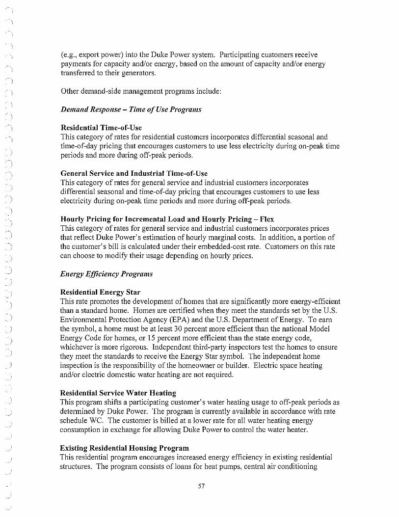
)
. \ ;
)
)
( e.g., export power) into the Duke Power system. Participating customers receive payments for capacity and/or energy, based on the amount of capacity and/or energy transferred to their generators.
Other demand-side management programs include:
De111and Response - Ti111e of Use Progra111s
Residential Time-of-Use This category of rates for residential customers incorporates differential seasonal and time-of-day pricing that encourages customers to use less electricity during on-peak time periods and more during off-peak periods.
General Service and Industrial Time-of-Use This category of rates for general service and industrial customers incorporates differential seasonal and time-of-day pricing that encourages customers to use less electricity during on-peak time periods and more during off-peak periods.
Hourly Pricing for Incremental Load and Hourly Pricing - Flex This category of rates for general service and industrial customers incorporates prices that reflect Duke Power's estimation of hourly marginal costs. In addition, a portion of the customer's bill is calculated under their embedded-cost rate. Customers on this rate can choose to modify their usage depending on hourly prices.
Energy Efficiency Programs
Residential Energy Star This rate promotes the development of homes that are significantly more energy-efficient than a standard home. Homes are certified when they meet the standards set by the U.S. Environmental Protection Agency (EPA) and the U.S. Department of Energy. To earn the symbol, a home must be at least 30 percent more efficient than the national Model Energy Code for homes, or 15 percent more efficient than the state energy code, whichever is more rigorous. Independent third-party inspectors test the homes to ensure they meet the standards to receive the Energy Star symbol. The independent home inspection is the responsibility of the homeowner or builder. Electric space heating and/or electric domestic water heating are not required.
Residential Service Water Heating This program shifts a participating customer's water heating usage to off-peak periods as determined by Duke Power. The program is currently available in accordance with rate schedule WC. The customer is billed at a lower rate for all water heating energy consumption in exchange for allowing Duke Power to control the water heater.
Existing Residential Housing Program This residential program encourages increased energy efficiency in existing residential structures. The program consists of loans for heat pumps, central air conditioning
57

I
\ ' /
systems, and energy-efficiency measures such as insulation, HV AC tune-ups, duct sealant, etc.
Special Needs Energy Products Loan Program This residential program encourages increased energy efficiency in existing residential structures for low-income customers. The program consists ofloans for heat pumps, central air conditioning systems and energy-efficiency measures such as insulation, HV AC tune-ups, duct sealant, etc.
Existing DSM Program Details
Program
Residential Air Conditioning Direct Load Control Residential Water Heating Direct Load Control Interruptible Power Service Standby Generator Control Energy Efficiency
Target Market Segment
Residential
Residential
Commercial and Industrial
Commercial and Industrial
All Segments
Customers
189,649
34,644
158
159
Expected Total MW Reduction (Summer)
324
6
342
94
Expected Total MW Reduction (2005/2006 Winter)
0
22
285
88
Results are implicit in the load forecast
58
INTERRUPTIBLE DEMAND SIDE PROGRAMS DATA
Number or Customers 2005 2006 2007 2008 2009 2010 2011 2012 2013 2014 2015 2016 2017 2018 2019 2020
AC/LC 191,897 189.649 187,401 185,153 182,905 180,657 178,409 176,161 173,913 171,665 169,417 167,169 164,921 162,673 162,673 162,673 \VII/LC 36,160 34,644 33,127 31.611 30,095 28,579 27,063 25,546 24,030 22,514 20,998 19,482 17,965 16,449 16,449 16,449 s 162 158 154 150 146 !42 JJS 134 130 JJO 130 130 JJO 130 JJO 130 G 156 159 162 165 168 171 174 177 ISO 183 186 189 192 195 198 201
Demand (Mw)
2005 2006 2007 2008 2009 2010 2011 2012 Winter Summer Winter Summer \\'inter Summer Winter Summer Winter Summer Winter Summer Winter Summer Winter Summer
AC/LC 0 332 0 324 0 316 0 308 0 301 0 294 0 287 0 281 \VII/LC 23 6 22 6 20 6 19 5 IS 5 17 5 16 4 15 4 IS 292 351 285 342 278 334 270 325 263 316 256 308 249 299 242 290 SC 86 92 88 94 89 96 91 98 93 99 94 IOI 96 103 98 105 Total 401 782 395 766 387 751 380 737 374 721 367 708 361 694 355 680
Demand (Mw)
2013 2014 2015 2016 2017 2018 2019 2020 Winter Summer Winter Summer Winter Summer Winter Summer \\'inter Summer Winter Summer Winter Summer Winter Summer
AC/LC 0 275 0 269 0 264 0 258 0 253 0 248 0 248 0 248 WII/LC 14 4 13 4 12 3 II 3 10 3 9 3 9 3 9 3 IS 234 282 234 282 234 282 234 282 234 282 234 282 234 282 234 282 SG 99 107 IOI 108 103 110 104 112 106 114 107 115 109 117 111 119 rot:11 347 668 348 663 349 659 349 655 350 652 350 647 352 649 354 651
I Estimated Customer Credits I Energy Target i\lilrkel Segment
2005 2006 2007 2008 2009 2010 (kwh) AC/LC Resitkn1a\
AC/LC s 6,141,000 s 6,069,000 s 5,997,000 s 5,925,000 s 5,853,000 s 5,781,000 AC/LC None \VII/LC Residen1al WII/LC s 868,000 s 83!,000 s 795,000 s 759,000 s 722,000 s 686,000 Wll/1.C None IS Commercial & Industrial IS s 13,046,000 s 12,724,000 S 12,402,000 s 12,080,000 s I 1,757,000 s ! 1,435,000 11s None SC Commercial & Industrial
SC s 2,856,000 s 2,911,000 s 2,966,000 s 3,021,000 s 3,075,000 s 3,130,000 '" None
Tot:11 S22.91 l,000 S22,535.000 $22.160.000 S21,785,000 S21,407,000 S21.032.000

DEMAND-SIDE MANAGEMENT ACTIVATION HISTORY
Time Frame Program Times Activated Reduction Ex~ected Reduction Achieved
9/2005 None 8/04- 8/05 None 8/03 - 8/04 None 8/02 - 8/03 None 8/01 - 8/02 Standby 1 Capacity Need 80MW 20MW
Generators 8/01 8/02 Interruptible 1 Capacity Need 403MW 370MW
Service 8/00- 8/01 Standby 1 Capacity Need 70MW 70MW
Generators 7/99 - 8/00 Standby 1 Capacity Need 70MW 70MW
Generators 9/97 - 9/98 Standby 2 Capacity Needs 68MW 58MW
Generators 9/97 - 9/98 Interruptible 1 Capacity Need 570MW 500MW
Service 9/96 - 9/97 Standby 4 Capacity Needs 62MW 50MW
Generators 9/96 - 9/97 Inte1n1ptible 1 Capacity Need 650MW 550MW
Service
60
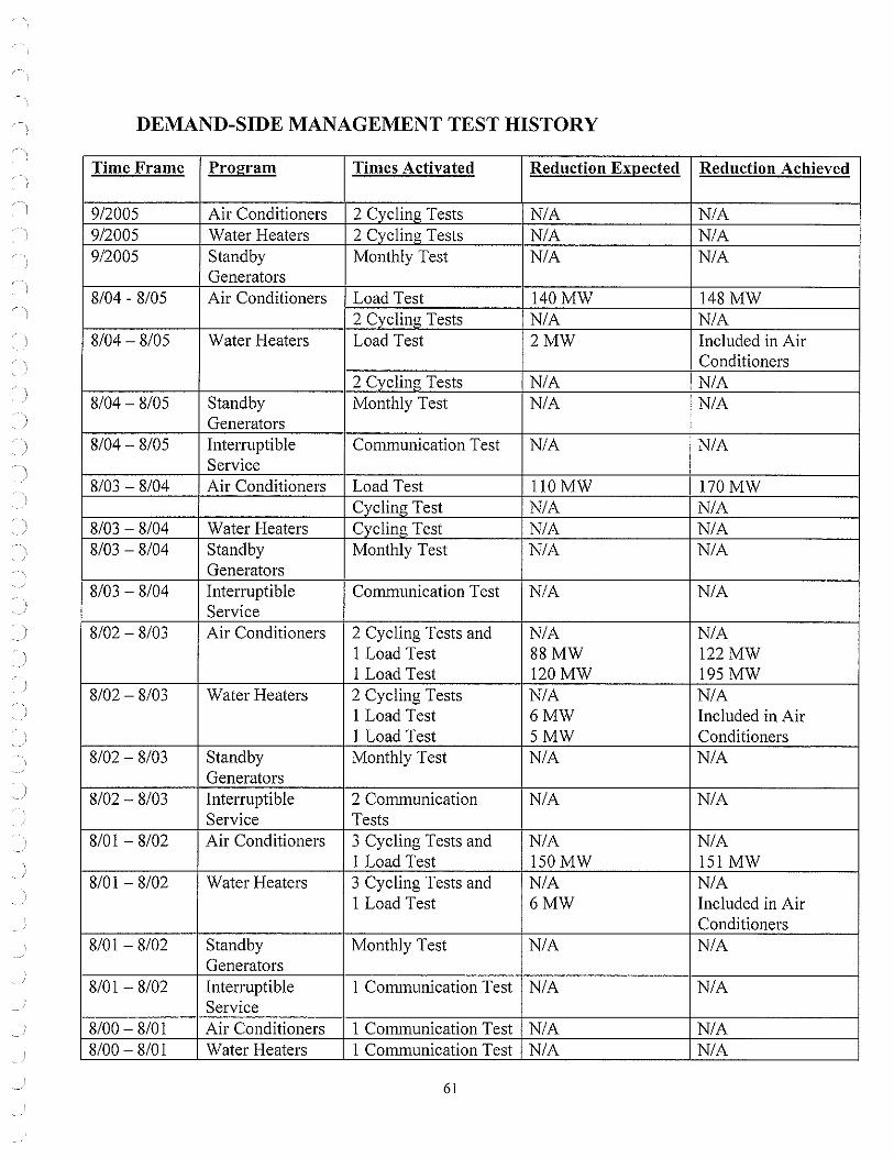
DEMAND-SIDE MANAGEMENT TEST HISTORY
Time Frame Program Times Activated Reduction Ex~ected Reduction Achieved
912005 Air Conditioners 2 Cycling Tests NIA NIA 912005 Water Heaters 2 Cycling Tests NIA NIA 912005 Standby Monthly Test NIA NIA
Generators 8104 - 8105 Air Conditioners Load Test 140MW 148MW
2 Cycling Tests NIA NIA 8104- 8105 Water Heaters Load Test 2MW Included in Air
Conditioners 2 Cvcling Tests NIA NIA
8104- 8105 Standby Monthly Test NIA NIA Generators
8104- 8105 Interruptible Communication Test NIA NIA Service
8103 - 8104 Air Conditioners Load Test ll0MW 170MW Cycling Test NIA NIA
8103 - 8104 Water Heaters Cvcling Test NIA NIA 8103 - 8104 Standby Monthly Test NIA NIA
Generators 8103 - 8104 Interruptible Communication Test NIA NIA
Service 8102 - 8103 Air Conditioners 2 Cycling Tests and NIA NIA
1 Load Test 88MW 122MW 1 Load Test 120MW 195MW
8102- 8103 Water Heaters 2 Cycling Tests NIA NIA 1 Load Test 6MW Included in Air 1 Load Test 5MW Conditioners
8102 - 8103 Standby Monthly Test NIA NIA Generators
8102 - 8103 Interruptible 2 Communication NIA NIA Service Tests
8101 - 8102 Air Conditioners 3 Cycling Tests and NIA NIA 1 Load Test 150MW 151 MW
8101 - 8102 Water Heaters 3 Cycling Tests and NIA NIA 1 Load Test 6MW Included in Air
Conditioners 8101 - 8102 Standby Monthly Test NIA NIA
Generators 8101 - 8102 Interruptible 1 Communication Test NIA NIA
Service 8100 - 8101 Air Conditioners 1 Communication Test NIA NIA 8100 - 8101 Water Heaters 1 Communication Test NIA NIA
61

8100- 8101 Standby Monthly Test NIA NIA Generators
8100- 8101 Interruptible 1 Communication Test NIA NIA Service
7199- 8100 Air Conditioners 1 Load Test 170-200 MW 175-200 MW 7199- 8100 Water Heaters I Load Test 6MW Included in Air
Conditioners 7199- 8100 Standby Monthly Test NIA NIA
Generators 7199 - 8100 Interruptible I Co111111unication Test NIA NIA
Service 9198 - 7199 Air Conditioners None NIA NIA 9198 - 7199 Water Heaters None NIA NIA 9198 - 7199 Standby Monthly Test NIA NIA
Generators 9198 - 7199 Inte1Tuptible 1 Communication Test NIA NIA
Service 9197 - 9198 Air Conditioners I Load Test 180MW 170MW 9197 - 9198 Water Heaters I Co111111unication Test NIA NIA
I Load Test 7MW 7MW 9197 - 9198 Standby Monthly Test NIA NIA
Generators 9197 - 9198 Interruptible I Communication Test NIA NIA
Service 9196 - 9197 Air Conditioners 1 Co111111unication Test NIA NIA 9196- 9197 Water Heaters None NIA NIA 9196- 9197 Standby Monthly Test NIA NIA
Generators 9196- 9197 Interruptible 2 Communication NIA NIA
Service Tests
62

l
APPENDIX E: SEASONAL PROJECTION OF LOAD, CAPACITY & RESERVES
The following table represents the generation strategy that performs best under a variety of sensitivities and scenarios to reflect the seasonal projection of load, capacity and reserves for Duke Power.
63

Seasonal Projections of Load, Capacity, and Reserves
W = WINTER, S = SUMMER w s w s w s w s w s w s w s w 05/06 2006 06/07 2007 07/08 2008 08/09 2009 09/10 2010 10/11 2011 11/12 2012 12113
Forecast 1 Duke System Peak 15,425 17,376 15,815 17,918 15,934 18,236 15,878 18,343 16,001 18,635 16,936 19,689 17,119 20,026 17,301
Cumulative System Capaciti' 2 Generating Capacil}' 19,976 19,257 19,967 19,236 19,979 19,235 19,627 18,908 19,616 18,924 19,535 18,518 19,237 18,518 19,237 3 Capacity Additions 0 2 0 50 0 0 0 0 50 0 0 0 0 0 0 4 Capacity Derates 0 0 (12) (26) (25) (25) 0 (11) (23) 0 0 0 0 0 0 5 Capacity Retirements 0 (7) 0 0 0 (88) 0 0 0 (108) (298) 0 0 0 0
6 Cumulative Generating Capacit~ 19,976 19,252 19,955 19,260 19,954 19,122 19,627 18,897 19,643 18,816 19,237 18,518 19,237 18,518 19,237
7 Cumulative Purchase Contracts 850 745 842 740 842 740 842 740 839 737 326 319 323 316 212 8 Cumulative Sales Contracts 0 0 0 0 0 0 0 0 0 0 0 0 0 0 0
9 Cumulative Future Resource Addition~ Peakingflntermediate 0 0 0 330 0 684 564 1,149 1,149 1,449 1,149 2,841 2,841 2,841 2,841 Base load 0 0 0 0 0 0 0 0 0 0 0 800 800 1,600 1,600
~
~,11 •
10 Cumulative Production Capacit}' 20,826 19,997 20,797 20,330 20,796 20,546 21,033 20,786 21,631 21,002 20,712 22,478 23,201 23,275 23,890
Reserves w/o DSM 11 Generating Reserves 5,401 2,621 4,982 2,412 4,862 2,310 5,155 2,443 5,630 2,367 3,776 2,789 6,082 3,249 6,589 12 % Reserve Margin 35.0% 15.1% 31.5% 13.5% 30.5% 12.7% 32.5% 13.3% 35.2% 12.7% 22.3% 14.2% 35.5% 16.2% 38.1% 13 % Capacity Margin 25.9% 13.1% 24.0% 11.9% 23.4% 11.2% 24.5% 11.8% 26.0% 11.3% 18.2% 12.4% 26.2% 14.0% 27.6%
DSM 14 Cumulative DSM Capacity 395 766 387 776 392 792 401 821 417 808 411 794 405 780 397
Existing DSM Capacity 395 766 387 751 380 737 374 721 367 708 361 694 355 680 347 Potential New DSM Capacit)' 0 0 0 25 12 55 27 100 50 100 50 100 50 100 50
15 Cumulative Equivalent Capacit}' 21.221 20,763 21,184 21,106 21,188 21,338 21,434 21,607 22,048 21,810 21,123 23,272 23,606 24,055 24,287
Reserves w/DSM 16 Equivalent Reserves 5,796 3,387 5,369 3,188 5,254 3,102 5,556 3,264 6,047 3,175 4,187 3,583 6,487 4,029 6,986 17 % Reserve Margin 37.6% 19.5% 34.0% 17.8% 33.0% 17.0% 35.0% 17.8% 37.8% 17.0% 24.7% 18.2% 37.9% 20.1% 40.4% 18 % Capacity Margin 27.3% 16.3% 25.3% 15.1% 24.8% 14.5% 25.9% 15.1% 27.4% 14.6% 19.8% 15.4% 27.5% 16.8% 28.8%
Sales {8PM) 19 Equivalent Sales 127 127 127 127
Equivalent Reserves 5663 3254 5236 3055 5254 3102 5556 3264 6047 3175 4187 3583 6487 4029 6986 % Reserve Margin 36.5% 18.6% 33.0% 17.0% 33.0% 17.0% 35.0% 17.8% 37.8% 17.0% 24.7% 18.2% 37.9% 20.1% 40.4% % Capacity Margin 26.7% 15.7% 24.7% 14.5% 24.8% 14.5% 25.9% 15.1% 27.4% 14.6% 19.8% 15.4% 27.5% 16.8% 28.8%

Seasonal Projections of Load, Capacity, and Reserves
W = WINTER, S = SUMMER s w s w s w s w s w s w s w s 2013 13/14 2014 14/15 2015 15/16 2016 16{17 2017 17118 2018 18{19 2019 19/20 2020
Forecast 1 Duke System Peak 20,393 17,497 20,727 17,602 21,062 17,758 21,413 17,957 21,771 18,116 22,140 18,273 22,505 18,381 22,870
Cumulative System Capacit}' 2 Generating Capacit}' 18,518 19,237 18,518 19,237 18,518 19,237 18,518 19,237 18,518 19,237 18,518 19,237 18,518 19,237 18,518 3 Capacity Additions 0 0 0 0 0 0 0 0 0 0 0 0 0 0 0 4 Capacity Derates 0 0 0 0 0 0 0 0 0 0 0 0 0 0 0 5 Capacity Retirements 0 0 0 0 0 0 0 0 0 0 0 0 0 0 0
6 Cumulative Generating Capacil} 18,518 19,237 18,518 19,237 18,518 19,237 18,518 19,237 18,518 19,237 18,518 19,237 18,518 19,237 18,518
7 Cumulative Purchase Contracts 205 117 117 72 72 72 72 72 72 72 72 72 72 72 72 8 Cumulative Sales Contracts 0 0 0 0 0 0 0 0 0 0 0 0 0 0 0
9 Cumulative Future Resource Addition~ Peaking/Intermediate 2,841 2,841 3,405 3,405 3,969 3,969 3,969 3,969 3,405 3,405 3,405 3,405 3,405 3,405 3,975 Base Load 1,600 1,600 1,600 1,600 1,600 1,600 2,717 2,717 3,834 3,834 3,834 3,834 3,834 3,834 3,834
~ ;i> m~
0
10 Cumulative Production Capacit~ 23,164 23,795 23,640 24,314 24,159 24,878 25,276 25,995 25,829 26,548 25,829 26,548 25,829 26,548 26,399
Reserves w/o DSM 11 Generating Reserves 2,771 6,298 2,913 6,712 3,097 7,120 3,863 8,038 4,058 8,432 3,689 8,275 3,324 8,167 3,529 12 % Reserve Margin 13.6% 36.0% 14.1% 38.1% 14.7% 40.1% 18.0% 44.8% 18.6% 46.5% 16.7% 45.3% 14.8% 44.4% 15.4% 13 % Capacity Margin 12.0% 26.5% 12.3% 27.6% 12.8% 28.6% 15.3% 30.9% 15.7% 31.8% 14.3% 31.2% 12.9% 30.8% 13.4%
DSM 14 Cumulative DSM Capacity 768 398 763 399 759 399 755 400 752 400 747 402 749 404 751
Existing DSM Capacit}' 668 348 663 349 659 349 655 350 652 350 647 352 649 354 651 Potential New DSM Capacll}' 100 50 100 50 100 50 100 50 100 50 100 50 100 50 100
15 Cumulative Equivalent Capacit} 23,932 24,193 24,403 24,713 24,918 25,277 26,031 26,395 26,581 26,948 26,576 26,950 26,578 26,952 27,150
Reserves w/DSM 16 Equivalent Reserves 3,539 6,696 3,676 7,111 3,856 7,519 4,618 8,438 4,810 8,832 4,436 8,677 4,073 8,571 4,280 17 % Reserve Margin 17.4% 38.3% 17.7% 40.4% 18.3% 42.3% 21.6% 47.0% 22.1% 48.8% 20.0% 47.5% 18.1% 46.6% 18.7% 18 % Capacity Margin 14.8% 27.7% 15.1% 28.8% 15.5% 29.7% H.7% 32.0% 18.1% 32.8% 16.7% 32.2% 15.3% 31.8% 15.8%
Sales (8PM) 19 Equivalent Sales
Equlvalent Reserves 3539 6696 3676 7111 3856 7519 4618 8438 4810 8832 4436 8677 4073 8571 4280 % Reserve Margin 17.4% 38.3% 17.7% 40.4% 18.3% 42.3% 21.6% 47.0% 22.1% 48.8% 20.0% 47.5% 18.1% 46.6% 18.7% % Capacity Margin 14.8% 27.7% 15.1% 28.8% 15.5% 29.7% 17.7% 32.0% 18.1% 32.8% 16.7% 32.2% 15.3% 31.8% 15.8%

ASSUMPTIONS OF LOAD, CAPACITY, AND RESERVES TABLE
The following notes are numbered to match the line numbers on the SEASONAL PROJECTIONS OF LOAD, CAPACITY. AND RESERVES table. All values are MW ex.cepl where shown as a Percent
1. Planning ls done for the peak demand for the Duke System including Nanlahala. Nantahala became a division of Duke Power August 3, 1998,
2. Generating Capacity must be onllne by June 1 to be Included in the available capaclty for the summer peak of that year. Capacity must be on line by Dec 1 lo be Included in the available capacity for the winter peak of that year. Includes 103 MW Nantahala hydro capacity, and total capacity for Catawba Nuclear Station less 832 MW to account for NCMPA 1 firm capacity sale to Southern Energy Company. Also, on January 1, 2006, Generating Capacity refiects a 277 MW reduction to account for PMPA termination of their interconnection agreement with Duke Power. Because the Lee CTs serve as a redundant safe-shutdown facility for Oconee Nuclear Station and are required by the NRC for operation of Oconee, the retirement of the existing CTs at Lee in 2006 will coincide with the addition of new CTs at Lee also In 2006 of 86 MW.
3. Capacity Additions reflect an estimated 2 MW Marshall unit double fiow IP rotor upgrade and 100 MW capacity uprate at the Jocassee pumped storage facility from increased efficiency from the new runners.
4. The expected Capacity Derates reflect the impact of parasitic loads from planned scrubber additions to various Duke fossil generating units. The units, In order of time sequence on the LCR table Is Marshall 1 - 4, Belews Creek 1 & 2. Allen 1 - 3, Cliffside 5, and Allen 4 & 5.
5. The 120 MW capacity retirement In 2010 represents the projected retirement date for all CTs at Rlverbend. The 88 MW capacity retirement In 2008 represents the projected retirement date for 4 CT's at Buzzard Roost(Wst). The 93 MW capaclty retirement ln 2010 represents the projected retirement date for the existing CTs at Buck. The 108 MW capacity retirement in 2010 represents the projected retirement date for 6 CT's at Buzzard Roost(GE). The 85 MW capacity retirement in 2010 represents the projected retirement date for CTs at Dan River. Duke has an operating lease for the 7 MW Buzzard Roost Hydro Unit which expires 6/30/2006. On May 23, 2000, the NRC issued to Duke a renewed facility operating license for its three nuclear units at Oconee. Duke
now has the option to operate its Oconee units for up to 20 years following the year 2013. Duke will evaluate on an ongoing basis the viability of operating past the year 2013. With respect lo planning purposes, the Oconee capacity is still in the plan.
The Hydro facilities for which Duke has submitted an application to FERC for licence renewal are assumed to continue operation through the planning horizon.
All retirement dates are subject to review on an ongoing basis.
7. Cumulative Purchase Contracts have several components:
A. Effective January 1, 2001, the SEPA allocation was reduced to 94 MW. This reflects self scheduling by Seneca, Greenwood, Saluda River, NCEMC, and NCMPA 1. The 94 MW reflects allocations for PMPA and Schedule 10A customers who continue to be served by Duke.
8. Piedmont Municipal Power Agency has given notice that it will be solely responsible for total load requirements beginning January 1, 2006. This reduces the SEPA allocation to 18 MW In 2006, which is attributed to Schedule 10A customers who continue lo be served by Duke.
C. Purchased capacity from PURPA Qualifying Facilities Includes the 88 MW Cherokee County Cogeneration Partners contract which began in June 1998 and expires June 2013 and miscellaneous other QF projects totaling 22 MW.
D. Purchase of 151 MW from Rowan County Power, LLC, Unit 2 began June 1, 2001 and expires December 31, 2005. E. Purchase of 152 MW from Rowan County Power, LLC, Unit 1 began June 1, 2002 and expires May 31, 2007. F. Purchase of 153 MW from Rowan County Power, LLC, Unit 3 began June 1, 2004 and expires May 31, 2008. G. Purchase of 153 MW from Progress Ventures, Inc. Rowan Unit 2 begins January 1, 2006 and expires December 31, 2010. H. Purchase of 153 MW from Progress Ventures, Inc. Rowan Unit 1 begins June 1, 2007 and expires December 31, 2010. I. Purchase of 153 MW from Progress Ventures, Inc. Rowan Unit 3 begins June 1, 2008 and expires December 31, 2010. J. Purchase of 160 MW from Dynegy/Rockingham unit begins January 1, 2006 and expires December 31, 2010.
9. Cumulative Future Resource Needs represent a combination of new capacity resources , shorUlong-term capacity purchases from the wholesale market, capacity purchase options, or capability increases which are being considered. Neither the date of operation, the type of resource, nor the size Is firm. Alf Future Resource Needs are uncommitted and represent capacity required to maintain the target planning reserve margin.
12. Reserve margin is shown for reference only. Reserve Margin = (Cumulatlve Capacity-System Peak Demand)/System Peak Demand
13. Capacity margin Is the industry standard term. A 14.6 percent capacity margin is equivalent to a 17.0 percent reserve margin. Capacity Margin = (Cumulative Capacity - System Peak Demand)/Curnulative Capacity
14. Cumulative Demand Sfde Management capacity represents the demand-side management contribution toward meeting the load. The programs reflected in these numbers include interruptible Demand Side Management programs designed to be activated during capacity problem situations.
66

. )
)
APPENDIX F: GENERATING UNITS UNDER CONSTRUCTION OR PLANNED
A list of generating units under construction or planned at plant locations for which property has been acquired, for which certificates have been received, orfor which applications have been.filed include:
Duke Power continues to assess the viability of all of its generating units in relation to new generation and purchased power. The Company filed preliminary information with the NCUC for a Certificate of Public Convenience and Necessity (CPCN) for a 600 MW combined cycle facility at the Buck Steam Station in Salisbury, N.C. in May 2005. Also, during May 2005, the Company filed preliminary information with the NCUC for a CPCN for up to 1600 MWs of pulverized coal generation at the Cliffside Steam Station in Cliffside, N.C.
67

APPENDIX G: PROPOSED GENERATING UNITS AT LOCATIONS NOT KNOWN
A list of proposed generating units at locations not !mown with capacity, plant type, and date of operation included to the extent known:
Line 9 of the Seasonal Projections of Load, Capacity, and Reserves for Duke Power identifies cumulative future resource additions needed to reliably meet customer load. Resource additions may be a combination of short/long-term capacity purchases from the wholesale market, capacity purchase options, and building or contracting of new generation. In the preliminary filings with the NCUC for the CPCNs at Buck and Cliffside Steam Stations, the Company noted its intent to also pursue CPCN s for coal and combined cycle capacity at sites in South Carolina. However, no decision has been made with regard to pursuit of South Carolina CPCNs at the time of the filing of this Plan.
68

APPENDIX H: TRANSMISSION LINES AND OTHER ASSOCIATED FACILITIES PLANNED OR UNDER CONSTRUCTION
The following table identifies significant planned construction projects and those currently under construction in Duke Power's transmission system.
PROJECT VOLTAGE LOCATION OF LINE CAPACITY CONNECTION STATION
Draytonville 230 kV Ripp Switching Double circuit Line Station to Riverview upgrade to bundled
Switching Station 795 conductor - 819 MVA
Kelsey Creek 230kV Tiger Tie to Pacolet Add second circuit to Line Tie existing tower line -
437MVA Dutchover Line 230 kV Riverbend Steam Reconfigure
Station to Lincoln Riverbend-Combustion Turbine McGuire Station (Schoonover) Line
and McGuire -Lincoln Combustion Turbine (Dutchman) Line to bypass McGuire - 598 MVA
In addition, NCUC Rule R8-62(p) requires the following information.
SCHEDULED OPERATION
June 1, 2006
June 1, 2006
Dec. 1, 2006
I. For existing lines, the information required on FERC Form 1, pages 422,423,424 and 425: (Please see Appendix K for Duke Power's current FERC Form 1 pages 422, 423,422.1, 423.1, 422.2, 423.2, 424 and 425.)
2. For lines under construction: • Commission docket number • Location of end point(s) • Length • Range of right-of-way width • Range of tower heights • Number of circuits • Operating voltage • Design capacity • Date construction started • Projected in-service date.
69

)
Duke Power has no lines rated at 161 KV or greater under construction.
3. For all other proposed lines, as the information becomes available: • County location of end point(s) • Approximate length • Typical right-of-way width for proposed type of line • Typical tower height for proposed type of line • Number of circuits • Operating voltage • Design capacity • Estimated date for starting construction • Estimated in-service date.
Duke Power has no proposed transmission lines rated at 161 kV or greater.
70

I
APPENDIX I: GENERATION AND ASSOCIATED TRANSMISSION FACILITIES SUBJECT TO CONSTRUCTION DELAYS
A list of any generation and associated transmission facilities under construction which have delays of over six months in the previously reported in-service dates and the major causes of such delays. Upon request from the Commission Staff, the reporting utility shall supply a statement of the economic impact of such delays:
There are no delays over six months in the stated in-service dates.
71

l
APPENDIX J: DEMAND-SIDE AND SUPPLY-SIDE OPTIONS REFERENCED IN THE PLAN.
Supply-Side Options
Supply-side options considered in the Annual Plan are subjected to an economic screening process to determine the most cost-effective teclmologies. Conventional, demonstrated and emerging technologies must pass a cost screen, a commercial availability screen, and a technical feasibility screen to be considered for further evaluation.
The data for each technology is based on research by Duke Power's generation team, the Electric Power Research Institute (EPRI) Technology Assessment Guide, and fuel and operating costs developed by internal and other sources. The EPRI information is not site-specific but reflects costs and operating parameters that are adjusted for installation in the Southeast.
Supply-side technologies evaluated were:
Conventional Technologies (technologies in common use): • 564 MW Combustion Turbine • 585 MW Combined Cycle • 400 MW Supercritical Conventional Fossil • 600 MW Supercritical Conventional Fossil • 800 MW Supercritical Conventional Fossil • 1200 MW Supercritical Conventional Fossil • 1600 MW Supercritical Conventional Fossil • 400 MW Circulating Fluidized Bed Coal, Atmospheric • 1050 MW Pumped Storage • 75 MW Wind Power
Demonstrated Technologies (technologies with limited acceptance and not in widespread use):
• 2234 MW Nuclear APl 000 • 20 MW Lead Acid Battery • 18 MW Advanced Battery • 350 MW Compressed Air Energy Storage • 600 MW Integrated Gasification Combined Cycle • 1 MW Molten Carbonate Fuel Cell
Emerging Technologies (technologies in the developmental stage or that have not been used in the electric utility in du shy):
• 5 MW Solar Photovoltaic
72

The following Levelized Busbar Cost charts provide an economic comparison of all the technologies considered.
Levelized Busbar Cost for Peaking Technologies
800.0 -----------------------------------~
700.0 ----------------------------------,---------,
600.0
ii, 500.0 •
14000 ----------------------- -----===---=~::;;;;==------i ;: ~ 300.0
200.0 --
100.0 -~~~ ---==--:::::=---~-----:----.-- -- ♦ -------------♦----·-----i r--
0.0 ----------------- -~------~ ---~-----~
500.0
450.0
400 0
350.0
~ 300.0 0 0
~ 250.0
~ 200.0 V,
150.0
100.0
50.0
0.0
0% 10% 20% 30% 40% 50% 60% 70% 80% 90%
Capacity Factor
I • CT F,Frame -+-Pumped Storage - Lead Acid Ball (HD) - Advanced Battery Wind Power CAES Solar PV
Levelized Busbar Cost for Base load & Intermediate Technologies
0% 10% 20% 30% 40% 50% 60%
Capacity Factor
" Fossil SupercBOO --..-Fossil Superc400 -e-CC585 -e-1GCC600 - AP1000-Nuclear -+-Fossil Superc1600 .....,Fossil Superc 600 Fuel Cell
70% 80%
......_CFBCoal -i --+- Fossil Superc 120~]
90%
Technologies which are commercially available, cost-effective and teclrnically feasible for use in the Carolinas were passed on to the quantitative analysis phase for further evaluation. The following points explain why various technologies were eliminated from further consideration.
• Although Circulating Fluidized Bed Coal is a conventional technology that is technically feas ible, it is one of the highest-cost generation technologies in the baseload duty cycle.
73

• Pumped Storage is a commercially available and technically feasible technology. However, Duke Power currently has more than 2,000 MW of pumped storage capacity in its generation portfolio. Pumped storage is designed to complement baseload generation and could be considered further in conjunction with future baseload additions.
• Wind Power is not a reliably dispatchable resource, limiting its competitiveness against peaking duty cycle technologies. Also, sufficient wind energy in the Duke Power service territory is found only in the ridge-lines of the North Carolina mountains which is currently under development restrictions.
• Advanced Battery technology is applicable for emergency operations (sh01i-term duty cycles) of three hours or less. The technology is also in the pilot phase, and not commercially available.
• Lead Acid Battery technology is not commercially available. As it is applicable only for sh01i-term emergency operation (one hour or less), it would not meet the general requirements for peaking duty cycle.
• Compressed Air Energy Storage is not a commercially available technology, and there are no viable sites in Duke Power's service territory to support it.
• Molten Carbonate Fuel Cell technology is currently undergoing developmental testing at several demonstration plants. It is not commercially available and is one of the higher-cost baseload duty cycle technologies.
• Solar Photovoltaic technology is still an evolving technology. It is not dispatchable without energy storage and is better suited for remote niche applications that require watt-to-kilowatt capability. In addition, large-scale photovoltaic applications are not competitive with peaking and intermediate duty cycle technologies.
The chart on the following page shows the technologies which are commercially available, cost-effective and technically feasible for use in the Carolinas. Combustion turbine is the most cost-effective technology for peaking duty cycles, combined cycle for intermediate duty cycles and an assortment of combined cycle, coal and nuclear for baseload duty cycles. The pricing for combined cycle depends on the price of natural gas. Duke Power will continue to monitor the cost variation between coal and nuclear technologies versus combined cycle as the price of natural gas changes.
74
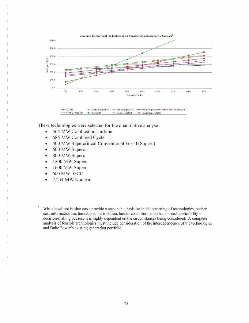
Levelized Busbar Cost for Technologies Considered In Quantitative Analysis3
600.0
_ 400.0
I :'.' 300.0
i ~ 200.0
100.0
0.0 0% 10% 20% 30% 40% 50% 60% 70% 80% 90%
Capacity Factor
---ccses " Fossil Superc800 .....-Fossil Superc400 -+-Fossil Superc1600 ---Fossil Superc600 - AP1000-Nuclear --- IGCC600 -+-Comb Turb564 _._Fossil Superc1200
These technologies were selected for the quantitative analysis: • 564 MW Combustion Turbine • 585 MW Combined Cycle • 400 MW Supercritical Conventional Fossil (Superc) • 600 MW Superc • 800 MW Superc • 1200 MW Superc • 1600 MW Superc • 600 MW IGCC • 2,234 MW Nuclear
While levelized busbar costs provide a reasonable basis for initial screening of technologies, busbar cost information has limitations. In isolation, busbar cost information has lim ited applicability in decision-making because it is highly dependent on the circumstances being considered. A complete analysis offeasible technologies must include consideration of the interdependence of the technologies and Duke Power's existing generation po11folio.
75

, )
)
Demand-Side Management
Duke Power is currently developing a DSM strategy that includes a more detailed analysis of the size and character of potential programs. This strategy will focus on identifying and implementing an appropriate amount of additional DSM. The 2005 Annual Plan includes 100 MW of additional demand-response program capability. This amount and the potential DSM programs which could be implemented may change based on further analysis and the results of the DSM strategy analysis underway.
Below is a summary of potential DSM programs considered in the planning process.
Direct Load Control Direct load control could be designed to target residential or commercial class customers and dispatched to a geographic region or systemwide. Potential load sources that could be directly controlled include water heating, air conditioning and swimming pool pumps. Estimated load impacts are between .5 kW and 1.6 kW per residential customer and 2.5 kW per commercial customer.
Interruptible Service Interruptible service could be designed to target large commercial or industrial customers and dispatched to a geographic region or systemwide. This program was assumed to have a load impact of approximately 2.06 MW per customer.
Standby Generation Standby generation could be designed to target commercial or industrial customers and could be dispatched specifically to a geographic region or system wide. This program was assumed to have a load impact of approximately 258 kW per customer.
Energy Efficiency Programs The DSM energy efficiency analysis was intended to be indicative of the level of opportunity available to Duke Power, rather than as a precise estimate of program costs and benefits.
76
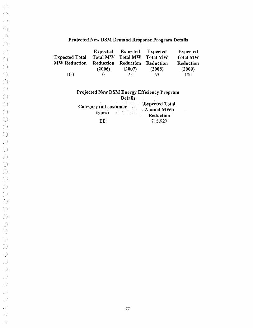
' J
Projected New DSM Demand Response Program Details
Expected Total MW Reduction
100
Expected Expected Expected Total MW Total MW Total MW Reduction
(2006) 0
Reduction (2007)
25
Reduction (2008)
55
Expected Total MW Reduction
(2009) 100
Projected New DSM Energy Efficiency Program Details
Category (all customer types)
EE
77
Expected Total AnnualMWh
Reduction 715,927

APPENDIX K: NON-UTILITY GENERATION/CUSTOMER-OWNED GENERATION/STAND-BY GENERATION:
In NCUC Order dated Feb. 20, 2003, in Docket No. E-100, Sub 97, the NCUC required Nmih Carolina utilities to provide a separate list of all non-utility electric generating facilities in the North Carolina portion of their control areas, including customer-owned and standby generating facilities, to the extent possible. Duke Power's response to that Order was based on the best available information, and the Company has not attempted to independently validate it. In addition, some of that information duplicates data that Duke Power supplies elsewhere in this Annual Plan.
78

CUSTOMER-OWNED STANDBY GENERATION
CITY STATE NAMEPLATE
PRIMARY FUEL TYPE PART OF TOTAL
KW SUPPLY RESOURCES Belmont NC 350 Unknown Yes1
Belmont NC 350 Unknown Yes1
Belmont NC 500 Unknown Yes1
Bessemer Citv NC 440 Unknown Yes1
Burlington NC 550 Unknown Yes1
Burlinqton NC 600 Unknown Yes1
I Burlinqton NC 650 Unknown Yes1
Burlinaton NC 225 Unknown Yes1
Burlington NC 200 Unknown Yes1
Burlinqton NC 1,150 Unknown Yes1
Butner NC 750 Unknown Yes1
Butner NC 1,250 Unknown Yes1
Carrboro NC 1,135 Unknown Yes1
Carrboro NC 500 Unknown Yes1
Carrboro NC 2,000 Unknown Yes1
Chaoel Hill NC 500 Unknown Yes1
Charlotte NC 1,750 Unknown Yes1
l Charlotte NC 500 Unknown Yes1
Charlotte NC 1,000 Unknown Yes1
Charlotte NC 1,250 Unknown Yes1
Charlotte NC 1,135 Unknown Yes1
Charlotte NC 1,135 Unknown Yes1
Charlotte NC 1,500 Unknown Yes1
Charlotte NC 219 Unknown Yes1
Charlotte NC 10,000 Unknown Yes1
Charlotte NC 200 Unknown Yes1
Charlotte NC 2,200 Unknown Yes1
Charlotte NC 700 Unknown Yes'
Charlotte NC 5,600 Unknown Yes'
Charlotte NC 4,000 Unknown Yes'
Concord NC 680 Unknown Yes'
Danbury NC 400 Unknown Yes1
Durham NC 1,300 Unknown Yes1
Durham NC 2,500 Unknown Yes1
Durham NC 3,200 Unknown Yes1
Durham NC 1,600 Unknown Yes'
Durham NC 1,400 Unknown Yes'
Durham NC 1,500 Unknown Yes1
Durham NC 2,250 Unknown Yes1
Durham NC 7,000 Unknown Yes1
Durham NC 1,900 Unknown Yes'
Durham NC 1,750 Unknown Yes'
Durham NC 4,525 Unknown Yes1
Durham NC 4,500 Unknown Yes1
Durham NC 6,400 Unknown Yes1

CUSTOMER-OWNED STANDBY GENERATION
CITY STATE NAMEPLATE
PRIMARY FUEL TYPE PART OF TOTAL
KW SUPPLY RESOURCES Durham NC 625 Unknown Yes1
Durham NC 2,000 Unknown Yes1
Eden NC 1,700 Unknown Yes1
Elkin NC 400 Unknown Yes1
Elkin NC 500 Unknown Yes1
Gastonia NC 910 Unknown Yes1
Gastonia NC 680 Unknown Yes1
Gastonia NC 12,500 Unknown Yes1
Graham NC 800 Unknown Yes1
Greensboro NC 1,350 Unknown Yes1
Greensboro NC 125 Unknown Yes1
Greensboro NC 1,000 Unknown Yes1
Greensboro NC 1,500 Unknown Yes1
Greensboro NC 2,000 Unknown Yes1
Greensboro NC 750 Unknown Yes1
Greensboro NC 1,280 Unknown Yes1
Greensboro NC 700 Unknown Yes1
Hendersonville NC 500 Unknown Yes1
Hendersonville NC 1,000 Unknown Yes1
Hendersonville NC 1,000 Unknown Yes1
Hickorv NC 1,500 Unknown Yes1
Hickorv NC 750 Unknown Yes1
Hickorv NC 1,000 Unknown Yes1
Hickorv NC 1,500 Unknown Yes1
Hickorv NC 1,040 Unknown Yes1
Hickorv NC 500 Unknown Yes1
Huntersville NC 2,950 Unknown Yes1
Huntersville NC 775 Unknown Yes1
Indian Trail NC 900 Unknown Yes1
Kinn NC 800 Unknown Yes1
Lexinaton NC 750 Unknown Yes1
Lexinaton NC 2,950 Unknown Yes1
Lincolnton NC 300 Unknown Yes1
Marion NC 650 Unknown Yes1
Matthews NC 1,450 Unknown Yes1
Mebane NC 400 Unknown Yes1
Midland NC 4,000 Unknown Yes1
Midland NC 6,000 Unknown Yes1
Monroe NC 400 Unknown Yes1
Mooresville NC 750 Unknown Yes1
Moraanton NC 200 Unknown Yes1
Mt. Airv NC 600 Unknown Yes1
Mt. Airv NC 750 Unknown Yes1
Mt. Hollv NC 210 Unknown Yes1
N. Wilkesboro NC 600 Unknown Yes1

CUSTOMER-OWNED STANDBY GENERATION
CITY STATE NAMEPLATE
PRIMARY FUEL TYPE PART OF TOTAL
KW SUPPLY RESOURCES N. Wilkesboro NC 155 Unknown Yes1
North Wilkesboro NC 1,250 Unknown Yes1
Pfafftown NC 4,000 Unknown Yes1
Reidsville NC 750 Unknown Yes1
Research Triannle NC 750 Unknown Yes1
Research Trianale NC 1,000 Unknown Yes1
Research Trianale NC 350 Unknown Yes1
Research Trianole NC 750 Unknown Yes1
Rural Hall NC 1,050 Unknown Yes1
Rutherfordton NC 800 Unknown Yes1
Salisburv NC 1,500 Unknown Yes1
Salisburv NC 1,500 Unknown Yes1
Shelbv NC 4,480 Unknown Yes1
Valdese NC 600 Unknown Yes1
) Valdese NC 800 Unknown Yes1
Welcome NC 300 Unknown Yes1
Winston NC 750 Unknown Yes1
Winston Salem NC 1,800 Unknown Yes1
Winston Salem NC 3,360 Unknown Yes1
Winston Salem NC 1,250 Unknown Yes1
Winston Salem NC 3,000 Unknown Yes1
Winston Salem NC 2,000 Unknown Yes1
Winston Salem NC 3,000 Unknown Yes1
Winston-Salem NC 500 Unknown Yes1
Winston-Salem NC 3,200 Unknown Yes1
Winston-Salem NC 400 Unknown Yes1
Winston-Salem NC 3,750 Unknown Yes1
Yadkinville NC 500 Unknown Yes1
Yadkinville NC 1,200 Unknown Yes1
Anderson SC 2,250 Unknown Yes1
Anderson SC 1,500 Unknown Yes1
Bullock Creek SC 275 Unknown Yes1
Clinton SC 447 Unknown Yes1
Clover SC 75 Unknown Yes1
Duncan SC 600 Unknown Yes1
Fort Mill SC 1,600 Unknown Yes1
Gaffnev SC 1,200 Unknown Yes1
Greenville SC 3,650 Unknown Yes1
Greenville SC 300 Unknown Yes1
Greenville SC 500 Unknown Yes1
Greenwood SC 2,400 Unknown Yes1
Greenwood SC 600 Unknown Yes1
Greer SC 125 Unknown Yes1
Greer SC 1,250 Unknown Yes1
Inman SC 165 Unknown Yes1

CUSTOMER-OWNED STANDBY GENERATION
CITY STATE NAMEPLATE
PRIMARY FUEL TYPE PART OF TOTAL
KW SUPPLY RESOURCES Kershaw SC 165 Unknown Yes1
Kershaw SC 1,500 Unknown Yes1
Lancaster SC 1,500 Unknown Yes1
Lancaster SC 300 Unknown Yes1
Lvman SC 1,000 Unknown Yes1
Mt. Holly SC 265 Unknown Yes1
Simpsonville SC 900 Unknown Yes1
Simpsonville SC 458 Unknown Yes1
Spartanburq SC 600 Unknown Yes1
Spartanbura SC 450 Unknown Yes1
Spartanburg SC 2,900 Unknown Yes1
Spartanburq SC 650 Unknown Yes1
) Spartanbura SC 1,600 Unknown Yes1
Tavlor SC 350 Unknown Yes1
) Van Wyck SC 450 Unknown Yes1
Van Wvck SC 365 Unknown Yes1
Walhalla SC 350 Unknown Yes1
Note 1: Nameplate rating is typically greater than maximum net dependable capability that generator contributes to Duke resources
)

PURPA QUALIFYING FACILITIES (SELLING POWER TO DUKE)
NAME CITY STATE NAMEPLATE
KW
Barbara Ann Evans - Caroleen Mills 2 Caroleen NC 324
Bullock Development Corp - Stice Shoals Hydro Shelby NC 600 Catawba County - Blackburn Landfill Newton NC 4,000
Ecusta Business Development Center Brevard NC 5,000
Haw River Hydro Co Saxapahaw NC 1,500
Mayo Hydropower, LLC - Avalon Dam Mayodan NC 1,275
Mayo Hydropower, LLC - Mayo Dam Mayodan NC 950
Mill Shoals Hydro Co - High Shoals Hydro High Shoals NC 1,800
Northbrook Carolina Hydro - Spencer Mtn Hydro Spencer Mtn NC 640
Northbrook Carolina Hydro - Turner Shoals Hydro Mill Springs NC 5,500
Salem Energy Systems, LLC Winston-Salem NC 4,270
South Yadkin Power, Inc Cooleemee NC 1,400
Spray Cotton Mills Eden NC 500
Steve Mason Enterprises-Harden Hydro Hardins NC 820
Steve Mason Enterprises-Lonq Shoals Hydro Lonq Shoals NC 900
Town of Lake Lure Lake Lure NC 3,600
Aquenerqy Systems Inc Piedmont SC 1,050
Aquenerav Systems Inc Ware Shoals SC 6,300
Aquenergy Systems Inc Cateechee SC 450
Aquenerqy Systems Inc Cateechee SC 440
Cherokee County Cooeneration Partners Gaffney SC 100,000
Converse Energy Inc Converse SC 1,250
Daniel Nelson Evans - Whitney Hydro Spartanburg SC 240
Northbrook Carolina Hydro - Boyds Mill Hydro Ware Shoals SC 1,500
Northbrook Carolina Hydro - Hollidays Bridge Hydro Anderson SC 3,500
Northbrook Carolina Hydro - Saluda Hydro Greenville SC 2,400
Pacolet River Power Co Clifton SC 800
Pelzer Hydro Co - Upper Hydro Pelzer SC 2,020
Pelzer Hydro Co - Lower Hydro Williamston SC 3,300
RCR Enterprises Inc Welcome NC -
Note 1: Nameplate rating generally exceeds the contract capacity negotiated for Duke Power Note 2: Formerly Clearwater Hydro
MERCHANT GENERATORS
NAME CITY STATE NAMEPLATE
KW
Dynegy Power Marketing, Inc. Bethany NC 810,000
Progress Ventures, Inc. Salisbury NC 500,000
Broad River Energy Center, LLC Gaffney SC 875,000
Note 1: Nameplate rating generally exceeds the contract capacity negotiated for Duke Power
PRIMARY FUEL TYPE
Hydro
Hydro
Landfill Gas
Coal
Hydro
Hydro
Hydro
Hydro
Hydro
Hydro
Landfill Gas
Hydro
Hydro
Hydro
Hydro
Hydro
Hydro
Hydro
Hydro
Hydro
Gas-fired Cogen
Hydro
Hydro
Hydro
Hydro
Hydro
Hydro
Hydro
Hydro Engine
Dynomometer
PRIMARY FUEL TYPE
Natural gas
Natural gas
Natural gas
PART OF TOTAL
SUPPLY RESOURCES
Yes1
Yes 1
Yes 1
Yes1
Yes1
Yes 1
Yes1
Yes 1
Yes 1
Yes1
Yes1
Yes1
Yes1
Yes 1
Yes 1
Yes1
Yes 1
Yes 1
Yes1
Yes1
Yes1
Yes1
Yes 1
Yes 1
Yes 1
Yes 1
Yes1
Yes 1
Yes1
No1
PART OF TOTAL
SUPPLY RESOURCES
Yes1
Yes1
No
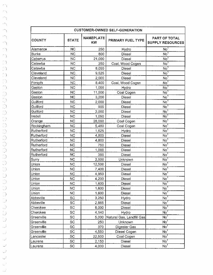
CUSTOMER-OWNED SELF-GENERATION
COUNTY STATE NAMEPLATE
PRIMARY FUEL TYPE PART OF TOTAL
KW SUPPLY RESOURCES
Alamance NC 250 Hvdro No1
Burke NC 800 Diesel No1
Cabarrus NC 21,000 Diesel No1
Catawba NC 250 Coal, Wood Coqen No1
Catawba NC 8,050 Diesel No1
Cleveland NC 9,525 Diesel No1
Cleveland NC 2,000 Diesel No1
Forsvth NC 8,400 Coal, Wood Coaen No1
Gaston NC 1,056 Hvdro No1
Gaston NC 11,500 Coal Cogen No1
Gaston NC 3,200 Diesel No1
Guilford NC 2,000 Diesel No1
Guilford NC 900 Diesel No1
Guilford NC 2,000 Diesel No1
Iredell NC 1,050 Diesel No1
Oran!'.le NC 28,000 Coal Coqen No1
Rockinaham NC 5,480 Coal Co!'.jen No1
Rutherford NC 1,625 Hvdro No1
Rutherford NC 4,800 Diesel No1
Rutherford NC 4,800 Diesel No1
Rutherford NC 750 Diesel No1
Rutherford NC 1,000 Diesel No1
Rutherford NC 350 Diesel No1
Surrv NC 2,500 Unknown No1
Union NC 12,500 Diesel No1
Union NC 7,400 Diesel No1
Union NC 4,950 Diesel No1
Union NC 4,200 Diesel No1
Union NC 1,600 Diesel No1
Union NC 1,600 Diesel No1
Union NC 1,600 Diesel No1
Abbeville SC 3,250 Hydro No1
Abbeville SC 2,865 Diesel No1
Cherokee SC 8,000 Diesel No1
Cherokee SC 4,140 Hydro No1
Greenville SC 5,000 Natural Gas, Landfill Gas No1
Greenville SC 250 Unknown No1
Greenville SC 370 Diaester Gas No1
Greenville SC 4,550 Diesel Coqen No1
Lancaster SC 22,500 Coal Co!'.jen No1
Laurens SC 2,150 Diesel No1
Laurens SC 4,000 Diesel No1

CUSTOMER-OWNED SELF-GENERATION
COUNTY STATE NAMEPLATE
PRIMARY FUEL TYPE PART OF TOTAL
KW SUPPLY RESOURCES
Oconee SC 700 Hvdro No1
Oconee SC 2,865 Diesel No1
Pickens SC 2,865 Diesel No1
Pickens SC 6,400 Diesel No1
Spartan burn SC 1,000 Hvdro No1
Greenville SC 2,550 Diesel No1
Union SC 15,900 Hvdro No1
Union SC 5,730 Diesel No1
York SC 42,500 Coal, Wood Coaen No1
York SC 29,000 Coal Coaen No1
York SC 3,000 Diesel No1
York SC 2,865 Diesel No1
York SC 2,865 Diesel No1
Note 1: The Load Forecast in the Annual Plan reflects the impact of these generating resources
UTILITY-OWNED STANDBY GENERATION
COUNTY STATE NAMEPLATE
PRIMARY FUEL TYPE PART OF TOTAL
KW SUPPLY RESOURCES
Alamance NC 275 Diesel No Granville NC 1,750 Diesel No Mecklenburn NC 1,750 Diesel No Mecklenbura NC 1,500 Diesel No Mecklenbura NC 150 Diesel No Mecklenburn NC 200 Diesel Na Mecklenbura NC 400 Diesel No Mecklenburn NC 1,000 Diesel Na Durham NC 1,750 Diesel No Wilkes NC 2,000 Diesel No

APPENDIX L: FERC FORM 1 PAGES
Following are Duke Power's 2004 FERC Form 1 pages 422,423,422.1, 423.1, 422.2, 423.2, 424 and 425.
86

Name of Respondent This Report Is: Dale of Report Year/Period of Report
Duke Energy Corporation (1) 0 An Original (Mo, Da, Yr) End of 2004/04 (2) (7 A Resubmission 12131/2004
TRANSMISSION LINE STATIST CS
1. Report infonnation concerning transmission lines, cost of lir:ies, and expenses for year. List each transmission line having nominal voltage of 132 kilovolts or greater. Report transmission lines below these voltages in group totals only for each voltage. 2. Transmission lines include all lines covered by the definitmn of transmission system pla_nt as given in the Uniform System of Accounts. Do not report substation costs and expenses on this page. 3, Report data by Individual lines for all voltages If so required by a State commission. 4. Exclude from this page any transmission lines for which plant costs are included in Account 121, Nonutility Property. 5. Indicate whether the type of supporting structure reported in column (e) is: (1) single pole wood or steel; (2) H-frame wood, or steel poles; (3) tower; or (4) underground construction If a transmission line has more than one type of supporting structure, indicate the mileage of each type of construction by the use of brackets and extra lines. Minor portions of a transmission !!ne of a different type of construction need not be distinguished from the remainder of the line. 6. Report in columns (f) and (g} the total pole miles of each transmission line. Show in column (f) the pole miles of line on structures the cost of which is reported for the line designated; conversely, show in column (g) the pole miles of line on structures the cost of which is reported for another Une. Report pole miles of line on leased or partly owned structures in column (g). In a footnote, explain the basis of such occupancy and state whether expenses with respect to such structures are included in the expenses reported for the line designated.
Line ",v., VULIAGt: (IW) Type of LENG~H ~ole wiles)
(Indicate wtiere All]! e ScfO Number No. other than u ergroun ltnes
Of 60 cvcle 3 nhase> Supporting report circuit miles) I un ~lfUcture un_qlru~iures Circuits From To Operating Designed Structure of Lin~ of 1_110 her
(b) (c) Desi(fa ed me (a) (d) (e) f) (g) (h)
1
2 Antioch Tie Appalachian Power 525,() 525.00 Tower 27.65 1
3 McGuire SW Antioch Tie 525.0( 525.00 Tower 54,35 1
4 McGuire SW Newport 525.0 525.00 Tower 32.26 1
5 McGuire SW Woodleaf SW 525.rn 525.00 Tower 29.97 I
6 Woodleaf SW Pleasant Garden Tte 525.rn 525.00 Tower 5309 I 7 Pleasant Garden Tie Parkwood 525.0, 525.00 Tower 49.66 1
8 Newport Rockingham 525.C 525.00 Tower 48.68 1
9 Oconee Newport 525.0 525.00 Tower 107.92 I
10 Oconee Norcross 525.0 52500 Tower 22.51 1
11 Oconee Jocassee 525.0 525.00 Tower 20.89 1
12 Jocassee McGuire 525.0 525.00 Tower t 1988 I
13 Jocassee Bad Creek 525.rn 525.00 Tower 9.24 I
14
15 Total 525kv Lines 576,10 12
16 17 Allen Pacolet - Tiger 230.0 230.00 Tower 80.22
18 Allen Beckerdite 230.0 230,00 Tower 79.89 2
19 Allen Riverbend 230.0I 230.00 Towor 12.50 2
20 Allen Woodlawn 230.0I 230.00 Tower 8.13 2
21 Antioch Tie Wilkes Tie 230.n 230.00 Tower 4.32 2
22 Beckerdite Pleasant Garden - Eno 230.0 230.00 Tower 71.26 2
23 Beckerdite Rural Hall 230.rn 230.00 Tower 107.03 2
24 Belews Creek Sadler tie 230,0I 230.00 Tower 26.31 2
25 Catawba Peacock 230.0 230.00 Tower 14,82 2
26 Central Anderson 230.C 230.00 Tower 23.13 2
27 Cliffside Pacolet 230.0 230.00 Tower 2301 2
28 Cliffside Shelby 230,0, 230.00 Tower 14.12 ' 29 East Durham Parkwood - Eno - Roxboro 230.0 230.00 Tower 33.00 2
30 Eno Tie - East Durham CP&L 230.r 230.00 Tower 15.80 2
31 Greenville Shady Grove - Central 230.C 230.00 Tower/Poles 34.0t 2
32 Greenville Shiloh - Pisgah Forest 230.0 230.00 Tower 30.82 2
33 Hartwell Anderson - Hodges 230.0 230.00 Tower 36.96 1
34 Jocassee Tie Tuckaseegee 230.nl 230.00 Tower 26,63 : 35 Lincoln CT Longview Tie 230.0 230.00 Tower 31.22 :
36 TOTAL 8,300.84 9(
FERG FORM NO. 1 (ED. 12-37) Page 422

Name of Respondent This ~ort Is: Date of Report Year/Period of Report
l Duke Energy Corporalion (1) An Original (Mo, Da, Yr) End of 2004/04
(2) Fi A Resubmission 12131/2004
TRANSMISSION LINE STATISTICS (Continued)
i 7, Do not report the same transmission line structure twice, Report Lower voltage Lines and higher voltage lines as one line. Designate In a footnote if you do not include Lower voltage lines with higher voltage lineS. If two or more transmission line structures support lines of the same voltage, report the pole miles of the primaiy structure in column (f) and U1e pole miles of the other line(s) in colum.n (g) 8. Designate any transmission line or portion thereof for which the respondent is not the sole owner. If such property is leased from another company,
I give name of lessor, date and terms of Lease, and amount of rent for year. For any transmission Hne other than a leased line, or portion thereof, for
I which the respondent is not the sole owner but which the respondent operates or shares in the operation of, furnish a succinct statement explaining the arrangement and giving particulars (details) of such matters as percent ownership by respondent in the line, name of co-owner, basis of sharing expenses of the Line, and how the expenses borne by the respondent are accounted for, and accounts affected. Specify whether lessor, co-owner, or
i other party is an associated company. 9. Designate any transmission line leased to another company and give name of Lessee, date and terms of lease, annual rent for year, and how determined. Specify whether lessee is an associated company. 10. Base the plant cost figures called for in columns (j) to (1) on the book cost at end of year.
CU!:::i I ut TIFJF(lnc!ude in COiumn Uf[ancf, EXPENSES, EXCEPT DEPRECIATION AND TAXES
Size of Land rights, and clearing right•of•way)
Conductor
and Material Land Construction and Total Cost Operation Maintenance Rents Total Line Other Costs Expenses Expenses
(o) Expenses
No. (i) (j) (k) (I) (m) (n) (p)
1
515 2
515 3
515 4 515 5
515 6 JS15 7 ~515 8
k-2515 9
:2515 10
515 11
h515 12
2515 13
20,434,4~ 97,499,092 117 ,933,52( 14
Ii 20,434,42 97,499,092 117,933,521 15
16 1154 & 1272 17
~54 1B 954&1272 19 ?156 20
54& 1272 21 k)54 22
54 & 2156 23
1272 24 -1272 25
.54 26
54 27
54 28
1272 29
1272 30
.54&2515 31 b54 32
54 & 2515 33
1272 34
li95 35
140,176,763 863,774,892 1,003,951,655 068,059 14,316,261 15,184,33( 36
FERG FORM NO. 1 (ED. 12-87) Page 423

Name of Respondent This 0ort Is: Date of Report Year/Period of Report
Duke Energy Corporation (1) An Original (Mo, Da, Yr) End of 2004/Q4 (2) Fi A Resubmission 12131/2004
TRANSMISSION LINE STATIST cs 1. Report information concerning transmission lines, cost of lil.1es, and expenses for year. List each transmission line having nominal voltage of 132 kilovolts or greater. Report transmission lines below these voltages in group totals only for each voltage. 2. Transmission lines include all lines covered by the definition of transmission system plant as given in the Uniform System of Accounts Do not report substation costs and expenses on this page. 3. Report data by Individual lines for an voltages if so required by a State commission. 4. Exclude from U1is page any transmission lines for which plant costs are included in Account 121, Nonulility Property. 5. Indicate whether the type of supporting structure reported in column (e) is: (1) single pole wood or steel; (2) H·frame wood, or steel poles; (3) tower; or (4} underground construction If a transmission line has more than one type of supporting structure, indicate the mileage of each type of construction by the use of brackets and extra lines. Minor portions of a transmission line of a different type of construction need not be distinguished from the remainder of the line. 6. Report ln columns (f) and (g) lhe total pole miles of each transmission line. Show in column (f) the pole miles of line on structures the cost of which is reported for the line designated; conversely, show in column (g} the pole miles of line on structures the cost of which is reported for another line. Report
) pole m11es of line on leased or partly owned structures in column (g}. In a footnote, explain the basis of such occupancy and state whether expenses wilh respect to such structures are Included in the expenses reported for the line designated.
Line "UN VULIAbt:..(KV) Type of LENGJr ~ole wiles) (Indicate where N" e 'l!' o Number No. other than u dergroun lines
60 cvcle, 3 nhase I Supporting report circuit miles) Of
)
Un titructure Unf~uu1wres Circuits From To Operating Designed Structure of. Lin~ o Anet er (a) (b) (c) (e) Oes1vna ed Line
(d) f) (g) (h)
1 Longview McDowell 230.fl< 230.00 Tower 31.96 2
2 Marshall Longview 230.n 230.00 Tower 29.06 2
3 Marshall Mitchell River 230.0< 230.00 Tower 49.49 2
4 Marshall Winecoff 230.0 230.00 Tower 24 36 2
5 McGuire-Harrisburg.Oakboro Newport - Catawba 230.0 230.00 Tower 139.44
6 McGuire SW Lincoln CT 230.0 230.00 Tower 5.34 2
7 Milchell Rural Hall 230.0 230.00 Tower 437d 2
8 Newport Parr - Bush River 230.0 230.00 Tower 6325 I
9 Oconee Central 230.0 230.00 Tower 17.64 2
10 Oconee Jacassee - Shiloh - Tiger 230.0 230.00 T ower/Po!es 85.54 2
11 Pisgah Forest Skyland 230.0( 230.00 Tower 14.42 2
12 Riverbend Lakewood (Pinoca) 230.fli 230.00 Tower f0.64 2
13 Riverbend McGuire•Marshall-Beckerdite 230.0 230.00 Tower 79.95 2
14 Riverbend Shelby-Peach Valley-Tiger 230.0 230.00 Tower 109.40 2
15 Tiger North Greenville 230.0 230.00 Tower 1840 2
16
17 Total 230kv Lines 1,395.81 63
1B
19 Natahala Tie Marble S.S. 161" 161.00 Tower 16.85 2
20 Natahala Tie Robbinsville S.S. 161.C 161.00 Tower 8.33 I
21 Santeetlah Tie Robbinsville S.S. 161.0< 161.00 Tower 11.14 I
22 Tuckasegee Tie Thorpe Hydro 161.0 161.00 Tower & Poles 2.52 I
23 Tuckasegee Tie Webster Tie - West Mill Tie 161.0 161.00 Tower 10.40 1
24 Webster Tie - Nantahala Plant 161.C 161.00 Tower 12 70 I
25 Webster Tie Lake Emory S.S. 161.Cl 161.00 Tower 11.93 1
26 West Mill Tie Lake Emory~ Nantahala Tie 16W 161.00 Poles 678 I
27 Tuckasegee Tie Webster Tie - NPL Portion 161.0< 161.00 Tower 136 2
28 Dan River Appalachian 138.0< 138.00 Tower/Poles 6.50 I
29 Horsehoe Tie Skyland CP&L 115.0< 115.00 Tower/Poles 7.63 I
30 Saluda Dam Busti River Tie 110.0 110.00 Tower 11 48 2
31 Clark Hill Greenwood 110.n 110.00 Wood Poles 35.76 1
32 Tuckaseegee Tie Thorpe Hydro 161.0 161.00 Tower 1.40 1
33 100kv Lines 100.0 100.00 Tower 2,992.40 34 100kv Lines 100.0 100.00 Pores 418.81
35 100kv Lines 100.0 100.00 Underground 1.84
36 TOTAL 8,30084 96
FERG FORM NO. 1 (ED. 12-87) Page 422.1

I I I l
.1
I }
I
I
Name of Respondent This ~ort Is: Date of Report Year/Period of Report
Duke Energy Corporation (1) An Original (Mo, Da, Yr)
End of 2004/Q4 (2) n A Resubmission 12/31/2004
RANSMISSION LINE STATISTICS (Continued)
7. Do not report the same transmission line structure twice, ~eport Lower voltage Lines and higher voltage lines as one line. Designate in a footnote if you do not include Lower voltage Hnes with higher voltage lines. If two or more transmission line structures support lines of the same voltage, report the pole miles of the primary structure in column (f) and the pole miles of the other line(s) in column _(g)._ 8, Designate any transmission line or portion thereof far which the respondent is not the sole owner. If such property is leased from another company, give name of lessor, date and terms of lease, and amount of rent for year. For any transmission tine other than a leased line, or portion thereof, for vJhich the respondent is not the sole owner but which the respondent operates or shares in the operation of, furnish a succinct statement explaining the arrangement and giving particulars (details) of such matters as percent ownership by respondent in the line, name of co-owner, basis of sharing expenses of Uie Line, and how the expenses borne by the respondent are accounted for, and accounts affected. Specify whether lessor, co-owner, or other party Is an associated company. 9. Designate any trarismission line leased to another company and give name of Lessee, dale and terms of lease, annual rent for year, and how detennined. Specify whether lessee !s an associated company. 1 a. Base the plant cost figures called for in columns (j) to (l) on the book cost at end of year.
vu;:, 1 ur UNI.: {Include m Column (l) Land, EXPENSES, EXCEPT DEPRECIATION AND TAXES Size of Land rights, and clearing righl•of.way)
Conductor and Material Land Construction and Total Cost Operation Maintenance Rents Total Line
Other Costs Expenses Expenses Expenses (i) U) (k) (I) (m) (n) (o) (p) No.
54 1
1272 2
J54 3
1272 4
354& 1272 5
795 6
954 & 2156 7
954 8
1795 & 1272 9
1272& 2156 10
~54 11
1795 & 954 12
954 & 1272 13
95 & 954 14
54 15
39,923.411 201,413,805 241,337,216 16
39,923,411 201,413,805 241,337,216 17
18
95 19
536 20
536 21
975 22
,0-_, 23
i95 24 - 25 36
95 26
195 27
m 28
77 & 12i2 29
,- 30 ,o
398 31
1272 32
33
34
35
140,176,763 863,774,892 1,003,951,655 868,069 14,316,261 15,184,331 36
FERG FORM N0.1 (ED. 12-87) Page 423.1

Name of Respondent This Report Is: Date of Report Year/Period of Report
Duke Energy Corporation (1) E:9 An Original (Mo, Oa, Yr) End of 2004/Q4 (2) Fi A Resubmission 12/31/2004
TRANSMISSION LINE STATISTICS
1, Report information concerning transmission lines, cost of lmes, and expenses for year. List each transmission line having nominal voltage of 132
kilovolts or greater. Report transmission lines below these voltages in group totals only for each voltage, 2. Transmission lines include all lines covered by the definition of transmission system plant as given in the Uniform System of Accounts. Do not report
substation costs and expenses on this page. 3. Report data by individual lines for a!! voltages if so required by a State commission. 4. Exclude from this page any transmission lines for which plant costs are included in Account 121, Nonutility Property. 5. Indicate whether the type of supporting structure reported in column (e) is: (1) single pole wood or steel; (2) H~frame wood, or steel poles; (3) tower; or (4) underground construction lf a transm~sion line has more than one type of supporting structure, indicate the mileage of each type of construction by the use of brackets and extra lines. Minor portions of a transmission line of a different type of construction need not be distinguished from the
remainder of lhe line 6. Report in columns (0 and (g) the total pole miles of each transmission line. Show in column (f) the pole mlles of line on structures the cost of which is reported for the line designated, conversely, show in column (g} the pole miles of line on structures the cost of which is reported for another line. Report pole miles of line on leased or partly owned structures in column (g). In a footnote, explain the basis of such occupancy and state whether expenses with
respect to such structures are included in the expenses reported for the line designated.
Line ,I Iv" VVL.lr\l.;lt::.{KV) Type of LENGtH ~ole ~iles) (Indicate where Nnt e 'ifo Number
No. other than u dergroun Imes 60 ~·cle, 3 nhase\ Supporting report circuil miles) Of
I un titructure Un,V_lru1wreS Circuits From To Operating Designed Structure of Line of Anet er
(a) (b) (c) Desi(lnated Lrne
(d) (e) f) (g) (h)
1
2 Total 100-161kv lines 3,557.83 17
3 4 66kv Lines 66,0 65,00 Poles 113.68 1
5 6 Total 66kv Lines 113.88 1
7
8 44kv Lines 44.0 44.00 Tower 264.85
9 44kv Lines 44.n 44,00 Poles 2,232.38
10 44kv Lines 44,01 44,00 Underground 0.73 I
) 11
12 Total 44kv Lines 2,497.96 1
13
14 33kv Lines 33,0i 33.00 Poles 5.46 I
15 22 kv Lines 22.rn 22.00 Poles 116.46
16 13kv Lines 13.0i 13.00 Poles 35,09
17 13kv Lines 13,0i 13,00 Underground 025 1
18
19 Total 13-33kv Lines 159.26 2
20
21
22
23 24
25 26
27
28
29
30
31
32
33
34
35
36 TOTAL 8,300.84 96
FERG FORM NO. 1 (ED. 12-87) Page 422.2
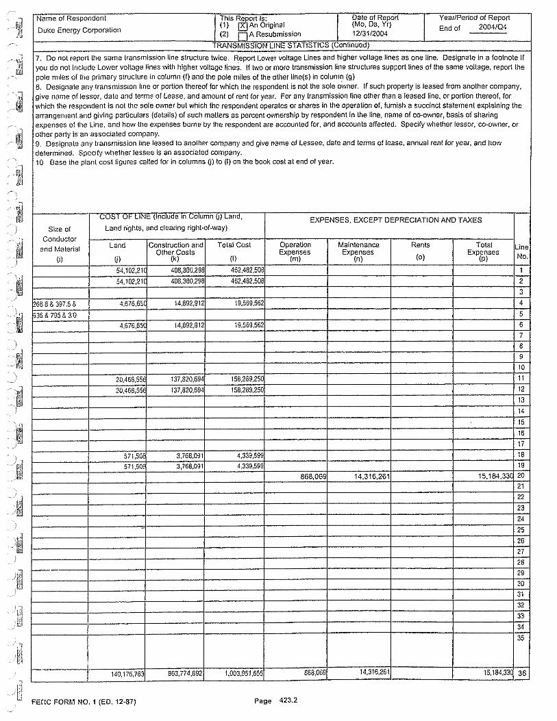
Name of Respondent This ~ort Is: Date of Report Year/Period of Report
Duke Energy Corporation (1) An Original (Mo, Da, Yr)
End of 2004/Q.j (2) Fi A Resubmission 12/31/2004
RANSMISSION LINE STATISTICS (\.,onlinued)
7. Do not report the same transmission line structure twice. ~eport Lower voltage Lines and higher voltage lines as one line. Designate in a footnote If you do not include Lower voltage lines with higher voltage lines. If two or more transmission line structures support lines of the same voltage, report the pole miles of the primary structure in column (f) and the pole miles of the other line(s) in column (g) 8. Designate any transmission line or portion thereof for which the respondent is not the sole Owner. If such property is leased from another company, give name of lessor, date and terms of Lease, and amount of rent for year. For any transmission line other than a leased line, or portion thereof, for which the respondent is not the sole owner but which the respondent operates or shares in the operation of, furnish a succinct statement explaining the arrangement and giving particulars (details) of such matters as percent ownership by respondent in lhe line, name of co-ovmer, basis of sharing
7
I expenses of the Line, and how the expenses borne by the respondent are accounted for, and accounts affected. Specify whether lessor, co-owner, or other party is an associated company. g_ Designate any transmission line leased to another company and give name of Lessee, date and terms of lease, annual rent for year, and how determined. Specify whether lessee is an associated company. 10 Base the plant cost figures called for in columns tj) to (I) on lhe book cost at end of year.
vvv 1 ...,, LIN!:: {Include m Column (J) Land, EXPENSES, EXCEPT DEPRECIATION AND TAXES Size of Land rights, and clearing right-of-\vay)
Conductor
and Material Land Construction and Total Cost Operation Maintenance Rents Total Line Other Costs Expenses Expenses Expenses
(1) ul (k) (I) (m) (n) (o) (p) No.
54,102,21 408,380,298 462,482,508 1
54,102,21 408,380,298 462,482,508 2
3
'66 8 & 397.5 & 4,676,65 14.892,912 19,569,562 4
t536 & 795 & 3/0 5
4.676,65 14,892,912 19,569,562 6
7
8
9
10
20.468,55 137,820,694 158,289,250 11
20,468,55 137,820,694 158,289,25 12
13
14
15
16
17
571,508 3,768,091 4,339,599 18
571,Soe 3,768,091 4,339,599 19
868,06 14,316,261 15,184,33( 20
21
22
23
24
25
26
27
28
29
30
31
32
33
34
35
140,176,763 863,774,892 1,003,951,655 868,069 14,316,261 15, 184,33( 36
FERG FORM NO. 1 (ED. 12-87) Page 423.2

Name of Respondent This Report Is: Date of Report Year/Period of Report
Duke Energy Corporation (1) ~ An Original (Mo, Da, Yr) End of 2004104 (2) Fi A Resubmission 12/3112004
TRANSMISSION LINES ADDED DURING YEAR
1. Report below the information called for concerning T_ransmission lines added or altered during the year. It is not necessary to report
minor revisions of lines. 2. Provide separate sublleadings for overhead and underw ground construction and show each transmission line separately. If actual
costs of competed construction are not readily available for reporting columns (I) to (o), it is permissible to report in these columns the
Line '-"" -- 1ur, Le~gih
s,,, ' '" ; IN:111,,,,IUI"',; l.,1r.~UI 1 V re r\ VI r'I.Ul, I ur;,
No. From To ,n Type Nunl-ber per Present Ultimate Miles Miles
(a) (b) (c) (d) (e) (0 (g)
1 OH Construction: New Lines
2 Eastfietd Retail Tap 040 Pole 13.00 1
3 Friendship Retail Tap 0.05 Pole 40.00 2
4 Island Ford Retail Tap 0.06 Pote 33.00 1
5 Rozzelles Relail Tap 0.08 Pole 38.00 1
6 South Hickory Relail Tap 2.80 10.00 2
7 Eastaloe Retail Tap 1.63 Pole 12.00 1
8 Holcombe Road Relail Tap 0.05 Po!e 20.00 1
9 Perry Tap Holcombe Road Relail Tap 4.28 11.00 2
10 Hildebran Junct.(Pons Line) Icard Retail Tap 0"01 H-Frame 40.00 1
11 Slerlile Tap 0.11 H-Frame 40.00 1
12
13
14
15
16
) 17
18
19
20 OH Construction: Major
21 Rebuild
22 Belton Tie Toxaway Tie 4 15 21.00 2
23 Newberry Main Whitmire Retail Tap 7.30 8.00 2
24 Tiger Tie East Greenville Tie 523 21.00 2
25 Spurrier Huntersville 2.69 Pole 11.0 1
26
27
28
29
30
31
32 -33
34
35
36
37
38
39
40
41
42
43
44 TOTAL 28.84 318.00 20
FERC FORM NO. 1 (REV. 12-03) Page 424

, Mame of Respondent This w□rt Is: Date of Report Year/Period of Report
Dul~e Energy Corpor;:i\ion (1) An Original (Mo, Da, Yr)
End of 2004104 (2) Fi A Resubmission 1213112004
TRANSMISSION LINES ADDED DURING YEAR (Continued)
] costs Designate, however, if estimated amounts are reported. Include costs of Clearing Land and Rights-of-Way, and Roads and
Trails, in column (I) wilh appropriate footnote, and costs of Underground Conduit in column (rn).
3. If design voltage differs from operating voltage, indicate such fact by footnote; also where line is other than 60 cycle, 3 phase,
] indicate such allier characteristic.
Ill ,IJl'11JllC!Vl"\S Voltage LIN~ 1.,V~ I Line
Size Specification Conf~uralion IIV Land and Poles, Towers Conductors Asset Total No, ancl pacing (Operating} Land Rights and Fixtures and Devices Retire. Costs
t (11) (i) Iii (k) (I) (m) (n) (o) (Pl 1
555-5 ACSR 100 71,647 213,849 131,069 416,565 2
1 954 0 AAC 100 9,121 495,313 303,S?G 808,013 3
55G.5 ACSR 100 9,494 56,827 34,829 101,150 4
556.5 ACSR 100 27,545 18,905 11,587 58,037 5
556.5 ACSR 100 55,596 1,210,548 741,949 2,008,093 6
I 556.5 ACSR 100 36,861 493,247 302,313 832,421 7
556 5 ACSR 100 40,859 25,043 65,902 B
95J.0 AAC 100 1,120,957 2,092,509 1,282,506 4,495,972 9
I 555.5 ACSR 44 6,146 17,702 10,850 34,698 10
555.5 f\CSR ,\,\ 37,900 23,229 61,129 11
12
• 13
14 .· 15
• 16
17
18
19
I 20
21
95,:0 A/i..C 100 1,216,729 745,737 1,962,466 22
• 556.5 f1CSR 100 2,666,003 1,634,002 4,300,005 23
951.Q AAC 100 2,643,612 1,620,278 4,263,890 24
556.5 t,CSR 44 320,421 14,1,342 464,768 25
t 26
27
28 ;
29
I 30
31 '
I 32
33
34
35
I 36
' 37
38
I 39
40
41
I 42
43
·•--~ 1,337,367 11,524,42t 7,011,313 19,873,109 44
g:i t~jFERC FORM NO. 1 (REV. 12-03) Page 425
APPENDIX M: OTHER INFORMATION (ECONOMIC DEVELOPMENT)
Customers Served Under Economic Development:
In the NCUC Order dated Nov. 15, 2002, in Docket No. E-100, Sub 97, the NCUC ordered North Carolina utilities to review the combined effects of existing economic development rates within the approved Annual Planning process and file the results in its short-term action plan. The incremental load (demand) for which customers are receiving credits under economic development rates and/or self-generation deferral rates (Rider EC), as well as economic redevelopment rates (Rider ER) as of October I, 2005, 1s:
Rider EC:
20 MW for North Carolina 22 MW for South Carolina
Rider ER:
0 MW for N01ih Carolina 3 MW for South Carolina
95

APPENDIX N: LEGISLATIVE AND REGULATORY ISSUES
Duke Power is subject to the jurisdiction of federal agencies including the Federal Energy Regulatory Commissions (FERC), EPA and the Nuclear Regulatory Commission (NRC), as well as state commissions and agencies. In addition, state and federal policy actions have potential impact on the Company. This section provides a high-level description of several issues Duke Power is actively monitoring or engaged in that could have an impact on new generation decisions.
Air Quality
Duke Power is required to comply with federal regulations such as the Clean Air Act's Nitrogen Oxide (NOx) State Implementation Plan (SIP) Call and the 2002 North Carolina Clean Smokestacks Act.
As a result of the North Carolina Clean Smokestacks Act, Duke Power will reduce sulfur dioxide (SO2) emissions by about 70 percent by 2013 from 2000 levels. The law also calls for additional reductions in NOx emissions by 2007 and 2009, beyond those required by the federal NOx SIP Call. This landmark legislation, which was passed by the North Carolina General Assembly in June 2002, calls for some of the lowest statemandated emission requirements in the nation, and was passed with Duke Power's input and support.
The following graphs show Duke Power's NOx and SO2 emissions reductions to comply with the federal NOx SIP Call and the 2002 North Carolina Clean Smokestacks Act.
180,000
160,000
140,000
120,000
100,000
80,000
60,000
40,000
20,000
0
Duke Power Coal-Fired Plants Annual Nitrogen Oxides Emissions (tons)
- -
1995 1996 1997 1998 1999 2000 2001 2002 2003 2004 2007 2009
Overall reduction of 80% from 1997 to 2009 attributed to controls to meet Federal Requirements and NC Clean Air Legislation .
96

Duke Power Coal-Fired Plants Annual Sulfur Dioxide Emissions (tons)
350,000 ~----------------------~
300,000 --t---- -------
250,000 +---<
200,000
150,000
100,000
50,000
0 1----'---'--,--L--'--,--L---'------,--L---'-------'--'------'--'------'-...J......,.-'---'-_,__-'-_,__-'------J
1995 1996 1997 1998 1999 2000 2001 2002 2003 2004 2009 2013
70 % Reduction from 2000 to 2013 attributed to scrubbers installed to meet NC Clean Air Legislation.
These cha11s do not show additional reductions that are necessary to comply with the federal Clean Air Interstate Rule.
Duke Power must also comply with two new federal rules to reduce air emissions: the Clean Air Interstate Rule and the Clean Air Mercury Rule.
Clean Air Interstate Rule (CA/R)
In May 2005, the EPA issued a Rule to Reduce Interstate Transpo1i of Fine Particulate Matter and Ozone (CAIR), which affects 28 states including North Carolina and South Carolina. The rule requires affected states to reduce emissions of SO2 and/or NOx_ The emissions controls that Duke Power is installing to comply with the North Carolina Clean Smokestacks Act will contribute significantly to achieving compliance with the CAIR requirements. Both No11h Carolina and South Carolina have taken steps to initiate the rulemaking process to implement CAIR.
Federal Clean Air Mercury Rule (CAMR)
In May 2005, the EPA published the Standards of Performance for New and Existing Stationary Sources: Electric Utility Steam Generating Units, also referred to as CAMR. The rule establishes mercury emission-rate limits for new coal-fired steam generating units, as defined in Clean Air Act section 111 ( d). It also establishes a nationwide mercury cap-and-trade program covering existing and new coal-fired power units. Both North Carolina and South Carolina have taken steps to initiate the rulemaking process to develop these plans.
The federal CAIR and CAMR rules were released concurrently because the emission controls that will be required under CAIR to reduce NOx and SO2 also reduce mercury
97

em1ss1ons. The controls that Duke Power is installing to comply with the North Carolina Clean Smokestacks Act will contribute significantly to achieving compliance with CAMR. However, both CAIR and CAMR may result in additional controls and/or costs for the Company beyond those required to meet the North Carolina Clean Smokestacks Act.
Global Climate Change
Duke Energy views climate change, paiiicularly potential policy responses to the issue, as a significant strategic business issue. Current U.S. policy includes a goal to reduce the greenhouse gas emissions intensity of the economy through voluntary measures. However, concern that greenhouse gas emissions from human activities may be influencing changes in the earth's climate system has resulted in a variety of local, state and regional responses, as well as increased policy debate at the federal level.
Duke Energy believes that a federal policy response is preferable to a patchwork of different state requirements, because it would be less costly to society and more effective in managing greenhouse gas emissions. In addition, the Company believes that the best course of action going forward is U.S. federal legislation that will result in a gradual transition to a lower-carbon-intensive economy, such as applying a federal-level carbon tax to all sectors of the economy.
Energy Policy Act of 2005
The Energy Policy Act of 2005 encourages investment in energy infrastructure, confers upon FERC a new role in policing transmission expansion, boosts electric reliability, and promotes a diverse mix of fuels to generate electricity. The Act increases protections for electricity consumers, encourages energy efficiency and conservation and repeals the Public Utility Holding Company Act (PUHCA).
There are several key issues that the Energy Policy Act can impact which are of importance to Duke Power. Some of those issues are:
• Reliability - The Energy Policy Act establishes an electric reliability organization, governed by an independent board, with FERC oversight.
• PUHCA and Merger Review - Repeals PUHCA transferring consumer protections to FERC and the states.
• Transmission Siting and Incentive Pricing - Encourages energy infrastructure investment, FERC backstop siting authority, and DOE identified "national interest electric transmission corridor" to be used by FERC, as a staiiing point, to address bottlenecks in the national grid.
• Native Load Protection - Assures firm transmission rights for serving native load. • Economic Dispatch- DOE to study and report on the benefits of economic
dispatch annually.
98

• Participant Funding - Provides that FERC "may approve" patiicipant funding plan if the plan is not unduly discriminatory or preferential with the result being just and reasonable rates.
Duke Power will closely monitor the implementation of the Energy Policy Act at the state and federal levels.
Hydroelectric Relicensing
On March 28, 2002, the FERC issued an Order Approving a Subsequent License to Duke Power for the Queens Creek Hydroelectric Project, FERC Project No. 2694. Over the next several years, Duke Power will be pursuing FERC license renewal approval for seven hydroelectric projects and will surrender one license.
During 2003, Duke Power filed applications to renew licenses for:
• Bryson • Dillsboro • Franklin • Mission
In 2004, Duke Power filed applications to renew licenses for:
• East Fork Project (Cedar Cliff, Bear Creek, and Tennessee Creek) • West Fork Project (Thorpe and Tuckasegee) • Nantahala Project (Nantahala, Dicks Creek, and White Oak)
In May 2004, Duke Power filed an application to surrender the license for its Dillsboro Project, a result of binding settlement agreements with stakeholders related to the relicensing of the East Fork, West Fork, and Nantahala Projects. Those settlement agreements were filed with FERC in January 2004 and call for the removal of the Dillsboro Dam.
On August 12, 2005, FERC issued mmual licenses for the Bryson, Franklin and Mission projects, authorizing continued operation under the terms of the previous licenses until July 31, 2006. IfFERC has not acted to issue a new license for any of those projects by that date, it will issue another annual license for that project.
Duke Power filed a Notice of Intent to File an Application for a New License for the Catawba/Wateree Project No. 2232 in 2003, five years prior to expiration of the license. The Catawba-Wateree Project includes the following developments:
• Bridgewater • Rhodhiss • Oxford
99

• Lookout Shoals • Cowans Ford • Mountain Island • Wylie • Fishing Creek • Great Falls • Dearborn • Rocky Creek • Cedar Creek and • Wateree.
Duke Power is currently working with numerous stakeholders in an effort to enter into a binding agreement.
The duration of a new FERC license for a hydropower facility can range from 30 to 50 years depending on various factors at the time of relicensing. FERC's normal time frame to issue new licenses is 24 to 3 6 months after submittal.
Generating Units with Plans for Life Extension
STATION NOTICE OF INTENT PRESENT LICENSE TO RELICENSE FILED EXPIRATION DATE
Brvson Project No. 2601 1/27/2000 7/31/2006 Dillsboro Project No. 1/19/2000 7/31/2006 2602 Franklin Proiect No. 2603 1/27/2000 7/31/2006 Mission Proiect No. 2619 2/15/2000 7/31/2006 East Fork Project No. 7/25/2000 1/31/2006 2698 West Fork Project No. 7/28/2000 1/31/2006 2686 Nantahala Project No. 8/7/2000 2/28/2006 2692 Catawba/Wateree Project 7/21/2003 9/1/2008 No. 2232
100

North Carolina Transmission Planning Process
Since May 2004, Duke Power has been working to develop a collaborative transmission planning process with North Carolina's major electric load-serving entities (LSEs). This effort has resulted in an agreement on a long-term comprehensive transmission planning process for Nmih Carolina, facilitated by an independent third party, Gestalt, LLC, with input from other market participants. The process is designed to preserve reliability as well as enhance access by LS Es to a variety of generation resources.
Independent Transmission Coordinator Plan
On July 22, 2005, Duke Power filed a plan with FERC for the independent and transparent operation of the Company's transmission system.
The filing is a result of a year-long process of input and refinement, based on feedback received from various stakeholders. In proposed amendments to its Open Access Transmission Tariff (OATT), Duke Power is seeking FERC approval to establish both an Independent Entity to serve as its transmission coordinator and an Independent Monitor to provide additional transparency and fair system administration. The Company is seeking FERC approval of the plan by early 2006.
Under the proposal, the Independent Entity will be charged with performing key transmission functions under Duke Power's OATT. Duke Power will remain owner and operator of its transmission system, maintaining ultimate responsibility for providing transmission service. Duke Power has retained the Midwest Independent System Operator (Midwest ISO) to perform the role oflndependent Entity.
While Duke Power is not joining the Midwest ISO, as Independent Entity the Midwest ISO is expected to perform a number of transmission functions, including:
• Evaluation and approval of all transmission service requests • Calculation of Total Transfer Capability and Available Transfer Capability • Operation and administration of the Duke Power Open-Access Same Time
Information System (OASIS) • Evaluation, processing and approval of all generation intercom1ection requests and
performance of related intercom1ection studies, and • Coordination of transmission planning.
The Independent Monitor will serve as an autonomous monitor of Duke Power's transmission system, providing a measure of neutrality in the Duke Power control area. The Independent Monitor will regularly perform a number of screens and other analyses related to the system, submitting quatierly repotis to both FERC and regulatory conunissions in North Carolina and South Carolina. Potomac Economics Ltd. has agreed to serve as Duke Power's Independent Monitor.
After two years of operation, Duke Power and the Independent Entity will convene a
IOI

stakeholder conference to receive input and comments regarding whether the Independent Entity and Independent Monitor have measurably improved transmission service.
102