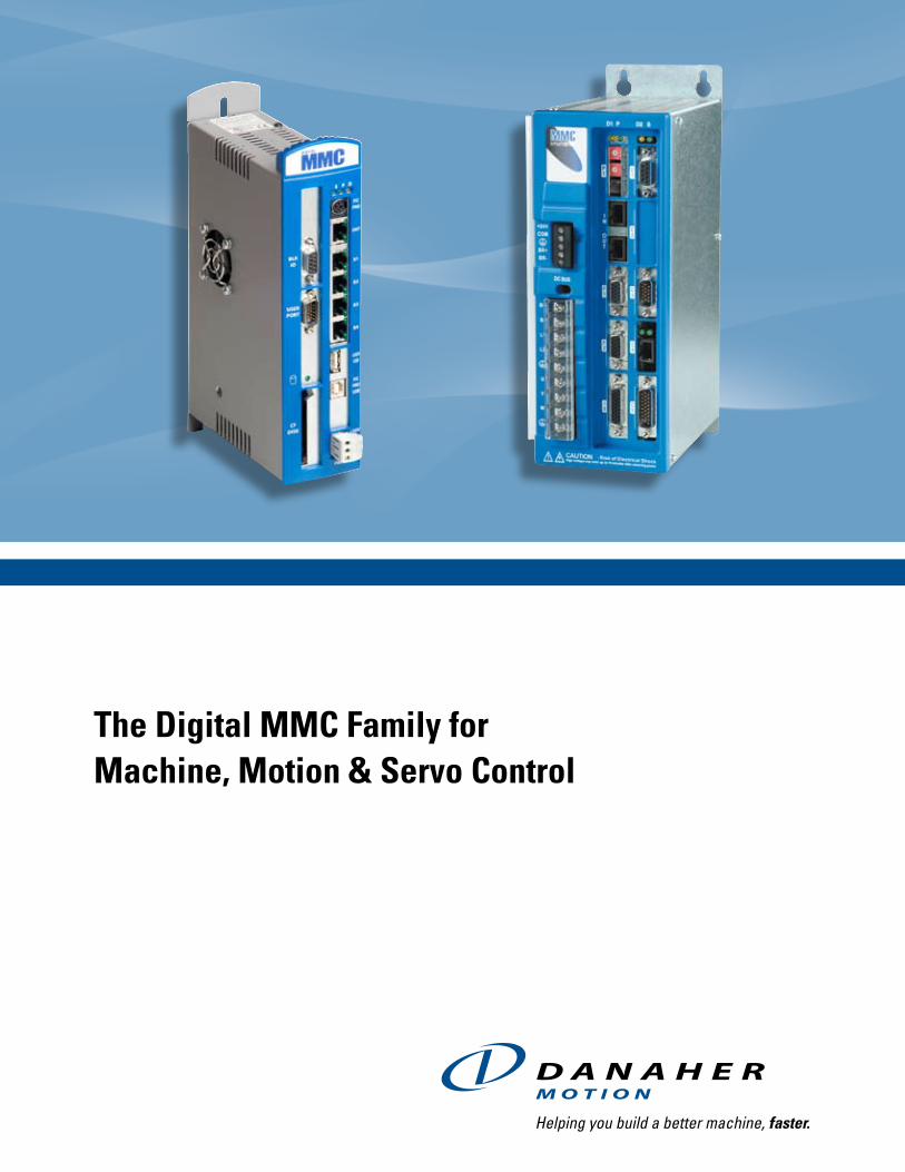
The Digital MMC Family for Machine, Motion & Servo Control
16
The Digital MMC Family for Machine, Motion & Servo Control
Transcript of The Digital MMC Family for Machine, Motion & Servo Control
The Digital MMC Family for Machine, Motion & Servo Control

www.danahermotion.com
The Digital MMC Family – A complete system solution
Servo Amplifiers – MMC Smart Drive amplifiers provide 500W to 65kW continuous output power in a compact, easy-to-apply package. Available in 230V single phase and 460V three phase versions, the MMC Smart Drives feature an integral power supply, standard auxiliary feedback, plug and play power and feedback cables to standard Danaher Motion motors.
Servo Motors - MMC Smart Drives connect with plug-and-play power and feedback cables to Danaher Motion’s AKM, Goldline DDR and Cartridge DDR motor families. Use Motion Solutions Sizing Software to select a motor and drive combination for your machine’s mechanical configuration.
The Digital MMC Family contains everything you need for a complete, high performance machine and motion control solution.
2

www.danahermotion.com
D64
The Digital MMC Family – A complete system solution
PiCPro Software – PiCPro is used for IEC61131 application program development, and drive setup and tuning. Through a single point connection to the Digital MMC Control, a virtual connection is made to every drive on the Digital network. Use the PiCPro oscilloscope and drive list to monitor and tune the drives on the network. Download parameters and firmware to all drives at once with a single click of the mouse. At the same time, use PiCPro for application program development with IEC61131 ladder logic, function block and structured text languages. PiCPro provides all of the tools you need for high-performance integrated machine and motion control applications.
Digital MMC Controls – The Digital MMC family of controls includes a drive-resident control card for applications up to 16 axes and a stand-alone control for applications up to 64 axes. The drives are daisy-chained to the control card using shielded CAT5 Ethernet cable. Up to 16 drives can be daisy-chained on one network branch.
Cimrex and Exter HMI – Use the Cimrex and Exter family of HMI terminals to provide machine status and feedback to the operator. With a complete family of Terminals including compact 2-line displays up to 15” color touch screens, and a tag-name database scheme to communicate to the Digital MMC Controls, these HMI terminals are the final piece to form a complete Digital MMC System.
3

www.danahermotion.com4
Stand-Alone Digital MMC – for applications up to 64 axes
User Serial Port Provides Application FlexibilityWhether your application requires a local operator interface or a serial link to another control device, the Digital MMC’s RS232/RS485 serial communications port will make the connection.
IEC61131 Application programming Software with powerful featuresPiCPro lets you choose between graphical ladder logic and function block or structured text programming to solve your machine logic and motion control application. Use on-line edit, animation, forcing and cut-and-paste examples to quickly implement your application. Drive setup and tuning is also integrated into PiCPro. Through a single serial or Ethernet connection, a virtual connection is established to all of the drives on the network.
Expand Via Our Block I/0Applications that require I/O beyond what is available on the control and the drives are easily expanded using Block I/O. A simple four-wire connection provides access to up to 77 I/O blocks that can be mounted locally or up to 200 feet apart. Select from our family of Block I/O modules including discrete I/O, analog I/O and motion I/O.
CF DiskCompact Flash disk to store your application program (future).

www.danahermotion.com
D64
Stand-Alone Digital MMC – for applications up to 64 axes
10/100 Ethernet for Device Connectivity The built-in 10/100 Ethernet port provides a wide variety of connectivity options. Connect to third-party devices using our OPC Server, Modbus TCP or other control protocols, transfer recipe or data files to and from the RAMDISK using TFTP file transfer, share data between controls using UDP packets, and access your plant network. You can also simultaneously run PiCPro over Ethernet either directly or remotely.
User USB USB Port – Accessible from the application program, this port allows you to communicate with other USB devices (future)
PiCPro USBUSB Port – Allows you to run PiCPro over USB, in-stead of serially or over Ethernet (future)
Expansion Capability The D32 and D64 controls are expandable. Up to four field-installable option modules can be used in a system. Use the 32 Input / 32 Output module to expand the I/O capability beyond what is available on the drives alone. Use the optional DeviceNet or Profibus module to control intelligent I/O devices.
5
Digital Motion Control NetworkDaisy-chain up to 16 Digital MMC Smart Drives off each branch with a simple RJ45 connection and readily available CAT5 cable. 230V and 460V versions of the drives are available in power ranges from 500W to 65kW. Real-time data from the drives such as torque, current and fault history is available to the application program over the Digital Link. Download firmware or parameters to all of the drives on the network at once with a single click of the mouse using PiCPro.
www.danahermotion.com6
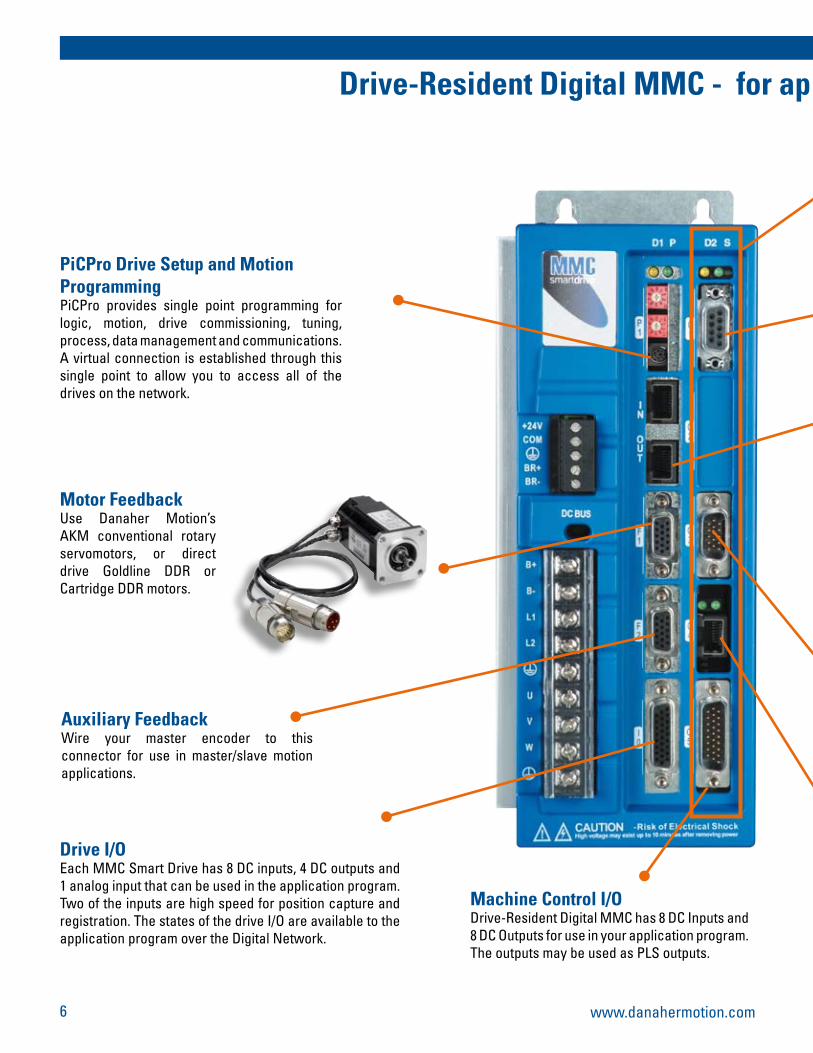
Drive-Resident Digital MMC - for ap plications from 1 to 16 axes of control
PiCPro Drive Setup and Motion ProgrammingPiCPro provides single point programming for logic, motion, drive commissioning, tuning, process, data management and communications. A virtual connection is established through this single point to allow you to access all of the drives on the network.
Motor FeedbackUse Danaher Motion’s AKM conventional rotary servomotors, or direct drive Goldline DDR or Cartridge DDR motors.
Auxiliary FeedbackWire your master encoder to this connector for use in master/slave motion applications.
Drive I/OEach MMC Smart Drive has 8 DC inputs, 4 DC outputs and 1 analog input that can be used in the application program. Two of the inputs are high speed for position capture and registration. The states of the drive I/O are available to the application program over the Digital Network.
Machine Control I/ODrive-Resident Digital MMC has 8 DC Inputs and 8 DC Outputs for use in your application program. The outputs may be used as PLS outputs.

www.danahermotion.com
D64
7
Drive-Resident Digital MMC - for ap plications from 1 to 16 axes of control
Digital MMC ControllerResides inside first Digital MMC Smart Drive. It can control the drive it is installed in and up to 15 additional drives.
Block I/0 OptionsApplications that require I/O beyond what is available on the control and the drives are easily expanded using Block I/O. A simple four-wire connection provides access to up to 77 I/O blocks that can be mounted locally or up to 200 feet apart. Select from our family of Block I/O modules including discrete I/O, analog I/O and motion I/O.
HMI Serial Port ConnectionThe serial port allows you to connect to our Cimrex and Exter operator interfaces, or a third-party serial device.
MMC Multi-Smart Drive Control SchemeA total of 16 MMC Smart Drives with 16 axes of control can be configured via a simple RJ45 cable connection
10/100 Ethernet for Device Connectivity The built-in 10/100 Ethernet port provides a wide variety of connectivity options. Connect to third-party devices using our OPC Server, Modbus TCP or other control protocols, transfer recipe or data files to and from the RAMDISK using TFTP file transfer, share data between controls using UDP packets, and access your plant network. You can also simultaneously run PiCPro over Ethernet either directly or remotely.

www.danahermotion.com
PiCPro - A Single-Point Programming Solution for Total Machine ControlPiCPro offers the most flexible tool set for motion application programming available. Motion instructions are as simple to use as ladder logic counters and timers. Sophisticated functions like multi-tasking provide the headroom to solve the toughest applications.
PiCPro Offers:• Single-point programming for logic, motion, process,
data management and communications.
• Complete ladder logic instruction set to make machine control easy.
• Drive setup and optimized tuning, integrated with application programming.
• Structured text programming for higher level operations.
• Powerful and robust motion instruction set including positioning, indexing, gearing, cam profiling and linear/circular interpolation.
• User-developed instruction (UDFBs) to create programs that can be reused in application after application.
• Powerful diagnostic functions including logic monitoring, data viewing, data forcing, servo tuning, and oscilloscope for quick start-up and maintenance.
• On-line edit of logic and motion to speed application development and troubleshooting.
• Real-time preemptive multi-tasking to solve high performance applications.
• Ethernet TCP/IP support for plant integration and remote application programming and debugging over the internet.
PiCPro - Programming SoftwarePiCPro - The Key to Successful Motion Control Applications
IEC 61131 Application Programming
PiCPro provides ladder logic programming for machine logic control, function block programming for motion control and structured text programming for high level operations, all in a fully-integrated environment. Based on the IEC 61131 standard for programming languages, PiCPro provides a rich standard instruction set with all the tools you’ll need to solve your entire machine and motion control application.
Powerful tools for the application engineer include over 200 standard functions, the ability to develop your own functions as well as time-tick, event-driven and servo-synchronous tasks.
Tools for maintenance include program logic animation, on-line edit of motion and logic instructions, variable forcing, and view lists. Servo tuning and view are built into the PiCPro environment to simplify start-up and maintenance.
Using universally understood ladder logic for machine control complemented by powerful function block programming for motion control, PiCPro provides the simplest yet most powerful tool for solving your motion application.
8

www.danahermotion.com
D64
PiCPro - The Key to Successful Motion Control Applications
PiCPro provides a fully-integrated programming environment for your entire application.
PiCPro’s motion control capabilities include positioning, indexing, gearing, cam profiling, and interpolation.
Solve applications such as printing, packaging and converting using the complete master/slave motion instruction set. Sophisticated continuous registration algorithms will adjust your motion profiles providing quality production at all machine speeds. For metal-cutting, welding, pick-and-place and glue-laying, use the interpolated motion instructions.
With up to 64 axes of digital interfaced motion control, PiCPro has the capabilities to solve your application.
Motion Capabilities To Handle Any Application Challenge
PiCPro application programs are structured to keep simple applications simple while offering the performance to solve the most challenging problems. True preemptive multi-tasking lets you focus the control’s processing power on your application’s highest priority process. User logic can execute in real-time synchronously with the servo update loop.
Real-Time Multi-Tasking To Solve Your Most Difficult Applications
Cam Profiling
Master Distance
Ratio
9
Linear & Circular Interpolation
Time
Velo
city
Gearing
Master Distance
Ratio
Main Program
Time-tick Task
Interrupt Task
Servo-tick Task
PriorityLow
Tim
e
High
Interrupt
Interrupt
Interrupt
Single-Point Solution

www.danahermotion.com
Danaher Motion's MMC Smart Drive servo amplifiers provide 500W to 65kW continuous output power in a compact, easy-to-apply package. Available in both 230VAC and 460VAC systems, MMC Smart Drives operate over wide line voltage range.
Application of MMC Smart Drives is simple. The integral power supply and plug-and-play cable sets simplify installation. Configuration, tuning and maintenance are intuitive using PiCPro software with features including basic and expert parameter views, a software storage oscilloscope and auto-tune.
Use PiCPro’s ladder logic. function block and structured text programming languages to develop complete multi-axis motion control solutions using the Digital MMC Family of Controls.
MMC Smart Drive Servo Amplifiers
10
Model PackageCont. Current
(Amps: 0-peak)Peak Current
(Amps: 0-peak)Dimensions
inches (mm) W x H x DMMC-SD-0.5-230 Micro 2.5 7.5 3.69(94) x 10.13(257) x 6.12(156)
MMC-SD-1.0-230 Micro 5.0 15.0 4.69(119) x 10.13(257) x 6.12(156)
MMC-SD-2.0-230 Micro 10.0 30.0 4.69(119) x 10.13(257) x 6.12(156)
MMC-SD-1.3-460 Size 1 3.0 6.0 4.14(105) x 13.66(347) x 8.35(212)
MMC-SD-2.4-460 Size 1 5.5 11.0 4.14(105) x 13.66(347) x 8.35(212)
MMC-SD-4.0-460 Size 2 9.0 18.0 4.15(106) x 16.85(428) x 11.35(288)
MMC-SD-6.0-460 Size 2 13.5 27.0 4.15(106) x 16.85(428) x 11.35(288)
MMC-SD-8.0-460 Size 2 18.0 36.0 4.15(106) x 16.85(428) x 11.35(288)
MMC-SD-12.0-460 Size 3 27.5 55.0 6.1(155) x 21.65(550) x 11.36(288)
MMC-SD-16.0-460 Size 3 36.5 73.0 6.1(155) x 21.65(550) x 11.36(288)
MMC-SD-24.0-460 Size 3 55.0 110 6.1(155) x 21.65(550) x 11.36(288)
MMC-SD-30.0-460 Size 4 69.3 110 7.5(190) x 26.18(665) x 12.71(322.63)
MMC-SD-42.0-460 Size 4 93.3 147 7.5(190) x 26.18(665) x 12.71(322.63)
MMC-SD-51.0-460 Size 4 117.4 189 7.5(190) x 26.18(665) x 12.71(322.63)
MMC-SD-65.0-460 Size 4 152.7 209 7.5(190) x 26.18(665) x 12.71(322.63)
Feature DescriptionAssignable Digital Inputs 8 24V DC optically isolated inputs
Assignable Digital Outputs 4 24V DC optically isolated outputs, short circuit protected
Assignable Relay Output 1 Relay Output (typically used for brake control)
Analog Input 1 Analog Input - 12-bit resolution
Feedback One (F1) Motor feedback - incremental encoder, high resolution encoder, resolver (resolver interface option module required)
Feedback Two (F2) Secondary feedback - incremental encoder
Drive Control Power 24V DC input for control power, independent of power section line voltage input
MMC Smart Drive Features
MMC Smart Drive Family
www.danahermotion.com
D64
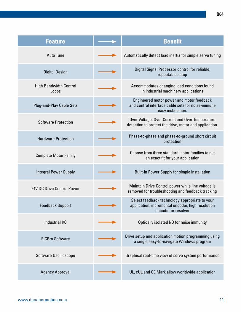
Feature Benefit
Auto Tune Automatically detect load inertia for simple servo tuning
Digital Design Digital Signal Processor control for reliable, repeatable setup
High Bandwidth ControlLoops
Accommodates changing load conditions foundin industrial machinery applications
Plug-and-Play Cable SetsEngineered motor power and motor feedback
and control interface cable sets for noise-immune easy installation.
Software Protection Over Voltage, Over Current and Over Temperature detection to protect the drive, motor and application.
Hardware Protection Phase-to-phase and phase-to-ground short circuit protection
Complete Motor Family Choose from three standard motor families to getan exact fit for your application
Integral Power Supply Built-in Power Supply for simple installation
24V DC Drive Control Power Maintain Drive Control power while line voltage is removed for troubleshooting and feedback tracking
Feedback SupportSelect feedback technology appropriate to your
application: incremental encoder, high resolution encoder or resolver
Industrial I/O Optically isolated I/O for noise immunity
PiCPro Software Drive setup and application motion programming usinga single easy-to-navigate Windows program
Software Oscilloscope Graphical real-time view of servo system performance
Agency Approval UL, cUL and CE Mark allow worldwide application
11

www.danahermotion.com
Whatever your application requirements, we have an operator interface terminal that fits.
From economical data entry/display terminals to sophisticated full color graphics touchscreens… all with a rich set of standard functions to make your next application the easiest yet.
Our Operator Interfaces Offer:
• A complete operator interface family ranging from simple text terminals to full color graphics touchscreens.
• Easy-to-use Information Designer configuration software programs both Exter and Cimrex terminals.
• Name-based communications allowing identical tag names in the control and Information Designer.
• Rugged packaging providing IP65 and NEMA 4 environmental ratings.
• A full set of functionality including recipe handling, event scheduling, password protection, report generation and more.
• Networking capability allowing multiple terminals per control... or multiple controls per terminal.
• Dual driver mode letting your operator terminal interface with two different controls per terminal.
• A complete set of standard graphic symbols and the ability to define custom graphics.
• Two families of operator interfaces to address all of your applications.
12
ExterTM T150
ExterTM K100
ExterTM K70
A compact, full-featured touch screen with a 5.7” display and 320 x 240 pixels.
Provides a high-end 15.1” color touch screen with 1024 x 768 pixels.
A keypad unit with 6.5”, 640 x 480 pixel resolution display.
A keypad unit with 10.4” display and 800 x 600 pixels.
ExterTM T60c
Operator Interface Terminals

www.danahermotion.com
D64
Provides a 4 x 20 character backlit LCD display and five function keys with slide-in labels.
13
A full graphics terminal providing 240 x 128 pixels with a bright monochrome display.
For simpler applications that will benefit from graphics as well as text display with 240 x 64 pixels.
A full graphics touchscreen display providing 220 x 240 pixels with built-in ethernet.
A simple data entry/display terminal ideal for basic applications, provides 2 x 20 character backlit LCD display and full keypad for data entry.
Cimrex 12
Cimrex 20
Cimrex 30
Cimrex 41
Cimrex 60
An economical gray scale or color graphics touchscreen with a 320 x 240 pixel passive color display and software selectable landscape or portrait display.
Cimrex 67 & 69
www.danahermotion.com14
Cim
rex
Feature Cimrex 12 Cimrex 20 Cimrex 30 Cimrex 41 Cimrex 60 Cimrex 67/69
Display Type Backlit LCD Backlit LCD Backlit LCD Backlit LCD Backlit LCD
Backlit LCDC67 - 16 Gray
Scale C69 - 256Colors
DisplayResolution
2 x 20charactertext only
4 x 20charactertext only
240 x 64pixels
320 x 240pixels3.8”
240 x 128pixels5.6”
320 x 240pixels5.7”
Function Keys/LED’s 3/0 5/5 8/16 NO 16/16 No
Touchscreen No NO No Yes No Yes
Memory 64K Flash 64K Flash 400K Flash 400K Flash 400K Flash 400K Flash
Memory,Expansion No No Option No Option Option
CommunicationOptions No No Ethernet
OptionalEthernetStandard
EthernetOptional
EthernetOptional
Power 24VDC 24VDC 24VDC 24VDC 24VDC 24VDC
Cut-OutDimensions 5.6”w x 3.5”h 5.8”w x 6.4”h 8.3”w x 7.8”h 5.6”w x 3.5”h 8.4”w x 9.1”h 7.85”w x 5.9”h
Mounting Depths 1.8” 1.5” 2.7” 1.9” 3.4” 2.8”
Ext
er
Feature Exter K30m ExterT40m/T40t
ExterT60m/T60c Exter K60c Exter T70 Exter T100 Exter T150 Exter K70 Exter K100
Display Type Backlit LCDT40m - 16
Greyscale T40t64K Color
STN-LCDT60m - 16
Greyscale T60c64K Color
STN-LCD 64KColor
TFT 64KColor
TFT 64KColor
TFT 64KColor
TFT 64KColor
TFT 64KColor
DisplayResolution
240 x 264 pixels3.5”
320 x 240 pixels3.5”
320 x 240 pixels5.7”
320 x 240pixels5.7”
640 x 480pixels6.5”
800 x 600pixels10.4”
1024 x 768pixels15.1”
640 x 480pixels6.5”
800 x 600pixels10.4”
Function Keys/LED’s 8/16 No No 16/16 No No No 16/16 22/20
Touchscreen No Yes Yes No Yes Yes Yes No No
Memory 32M Flash,64M RAM
32M Flash,64M RAM
32M Flash,64M RAM
32M Flash,64M RAM
32M Flash,64M RAM
32M Flash,64M RAM
32M Flash,64M RAM
32M Flash,64M RAM
32M Flash,64M RAM
Memory,Expansion No No No No Option CompactFlash slot available for adding optional cards for expansion of
memory, data back-up, data storage and transfer of data and projects
Communication Options Ethernet, USB Host Ethernet 10/100, USB Host, USB Device
Power 24VDC 24VDC 24VDC 24VDC 24VDC 24VDC 24VDC 24VDC 24VDC
Cut-OutDimensions 6.54” w x 5.87 h” 5.47”w x 4.13”h 7.09”w x 5.12”h 9.45”w x 5.12”h 7.44”w x 5.4”h 10.4”w x 8.1”h 14”w x 11”h 9.7”w x 5.5”h 13.5”w x 8.3”h
Mounting Depths 2.2” 2.2” 2.2” 2.2” 2” 2.1” 2.2” 2.2” 2.1”
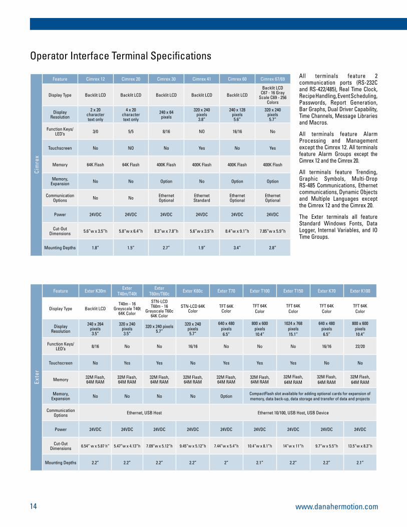
Operator Interface Terminal Specifications
All terminals feature 2 communication ports (RS-232C and RS-422/485), Real Time Clock, Recipe Handling, Event Scheduling, Passwords, Report Generation, Bar Graphs, Dual Driver Capability, Time Channels, Message Libraries and Macros.
All terminals feature Alarm Processing and Management except the Cimrex 12. All terminals feature Alarm Groups except the Cimrex 12 and the Cimrex 20.
All terminals feature Trending, Graphic Symbols, Multi-Drop RS-485 Communications, Ethernet communications, Dynamic Objects and Multiple Languages except the Cimrex 12 and the Cimrex 20.
The Exter terminals all feature Standard Windows Fonts, Data Logger, Internal Variables, and IO Time Groups.

www.danahermotion.com
D64
Family Member Description Dimensions: Inches (mm) W x H x D
Cont
rols
MMC-D1 1 1/2 Axis Installs inside Digital MMC Smart Drive
MMC-D2 2 Axis Installs inside Digital MMC Smart Drive
MMC-D4 4 Axis Installs inside Digital MMC Smart Drive
MMC-D16 16 Axis Installs inside Digital MMC Smart Drive
MMC-D32 32 Axis 2.25" (57.15) x 9.6" (243.84) x 5.3" (134.52)
MMC-D64 64 Axis 2.25" (57.15) x 9.6" (243.84) x 5.3" (134.52)
Opt
ion
MMC-32 in / 32 Out 32 DC Inputs and 32 DC outputs 1.28 (35.21) x 9.59 (243.59) x 5.25 (133.3)
MMC-AIO 4 1/2 Axis Interface Expansion Module* 1.28 (35.21) x 9.59 (243.59) x 5.25 (133.3)
MMC-D DeviceNet Module 1.28 (35.21) x 9.59 (243.59) x 5.25 (133.3)
MMC-P Profibus Module 1.28 (35.21) x 9.59 (243.59) x 5.25 (133.3)
Digital MMC Control Family
Digital MMC Control Feature
Feature MMC-D1 MMC-D2 MMC-D4 MMC-D16 MMC-D32 MMC-D64
Closed Loop Axes 1 2 4 16 32 64
Digitizing (Read-Only or Half) Axes 1 2 4 16 32 64
Processor Speed 64 MHz 64 MHz 64 MHz 96 MHz 400 MHz 400 MHz
Application Memory 1.3 MBytes 1.3 MBytes 1.3 MBytes 1.3 MBytes 3 MBytes 3 MBytes
General Purpose Inputs (24VDC) 8 8 8 8 0 0
General Purpose Outputs (24VDC) 8 8 8 8 0 0
Drive I/O 8 Input; 4 Outputs, 1 Analog Input (12-bit) per drive in the system
User Serial Port Yes Yes Yes Yes Yes Yes
Block I/O Capability No Yes Yes Yes Yes Yes
On-Board Ethernet Capability No Yes Yes Yes Yes Yes
Option Module Support No No No No Yes - up to 4 Yes - up to 4
32 I/O, Ethernet, DeviceNet, Profibus N/A N/A N/A N/A Optional Optional
15
* Future Option

EUROPE
FranceDanaher MotionC.P. 8001812, Rue Antoine Becquerel - Z.I. SudF-72026 Le Mans Cedex 2FrancePhone: +33 (0) 243 50 03 30 Fax: +33 (0) 243 50 03 39 E-mail: [email protected]
GermanyDanaher Motion GmbHWacholderstr. 40-42D-40489 DüsseldorfGermanyPhone: +49 (0) 203 9979-0Fax: +49 (0) 203 9979-155E-mail: [email protected]
ItalyDanaher Motion srlLargo Brughetti ZI20030 Bovisio Masciago (MI)ItalyPhone: +39 0362 59 42 60Fax: +39 0362 59 42 63E-mail: [email protected]
SwedenDanaher MotionBox 9053SE-29109 KristianstadSwedenPhone: +46 (0) 44 24 67 00Fax: +46 (0) 44 24 40 85E-mail: [email protected]
UKDanaher MotionChartmoor Road,Chartwell Business ParkLeighton Buzzard, BedfordshireLU7 4WG. UKPhone: +44 (0) 1525 243 243Fax: +44 (0) 1525 243 244E-mail: [email protected]
USA, CANADA or MEXICO
Danaher Motion203A West Rock RoadRadford, VA 24141 USAPhone: 1-540-633-3400Fax: 1-540-639-4162E-mail: [email protected]: [email protected]
ASIA
ChinaDanaher MotionRm 2205, Scitech Tower22 Jianguomen Wai StreetBeijing, China, 100004Phone: +86 10 6515 0260Fax: +86 10 6515 0263E-mail: [email protected]
JapanDanaher Motion Japan2F, Sigma Hatchobori Bldg2-7-1, Hatchobori, Chuo-kuTokyo 104-0032 JapanPhone: +81-3-6222-1051Fax: +81-3-6222-1055E-mail: [email protected]
www.danahermotion.com
Job
No.
PS
7500
ML
0825
06 2
0060
8-01
P10
0©
2006
Dan
aher
Mot
ion(
tm).
All
right
s re
serv
ed.
Info
rmat
ion
& s
peci
ficat
ions
sub
ject
to c
hang
e at
any
tim
e. A
ll tr
adem
arks
pro
pert
y of
thei
r res
pect
ive
owne
rs.