FovVideoVDP: A visible difference predictor for wide field ...

THE DIFFERENCEIS CLEARLY VISIBLEMAGNA-SITE MAGNETIC LIQUID LEVEL GAUGE

OPERATING PRINCIPLE
The KENCO Magna-Site is a magnetic liquid level gauge used to determine the volume of liquid contained within a tank. Because the Magna-Site eliminates the need for glass, high pressure applications and hazardous locations are protected from the danger of a chemical spill due to glass failure.
The KENCO Magna-Site utilizes three major components: the gauge housing chamber, the magnetic float, and the magnetic flag assembly.
The gauge housing chamber is typically mounted adjacent to the side of the tank. It is constructed to withstand the same temperatures and pressures as the tank itself. It is equipped with the appropriate tank mounting connections for easy installation and to allow equalization of liquid level in tank and gauge. Inside the gauge housing chamber is the magnetic float, which contains radially-positioned magnets to provide a 360 degree magnetic flux field. Each float is internally weighted based on specific gravity so that the liquid level in the gauge coincides with the location of the magnets inside the float.
Attached to the gauge housing chamber is the magnetic flag assembly. This is the visual means of liquid level indication for the KENCO Magna-Site. The assembly is made up of a series of bicolored, fluorescent flags. As the magnetic float rises and falls with the liquid level in the gauge housing chamber, a magnet embedded in each flag reacts to the 360 degree magnetic flux of the float. This magnetic interaction causes each flag to rotate 180 degrees. The flags below the magnetic flux of the float will flip to fluorescent green, while those flags above the float level remain bright white. Other colors are available upon request.
When your application priorities are safety, visibility, and accuracy, the KENCO Magna-Site is the low-maintenance, cost-effective solution.
GAUGE FEATURES
• Maximum safety – No glass is used in the construction
• Optimum visibility – Fluorescent flags are visible from great distances
• Float with 360 degree magnetic flux–Maintains a strong magnetic field in all directions to provide constant interac-tion with flag assembly, level switches and magnetostrictive transmitter
• Float is internally weighted based on specific gravity so that location of magnets inside float coincide with liquid level in gauge
• Double flag protection–Flags are hermetically sealed inside a Teflon® encapsulated assembly which is shrouded by a 300 series stainless steel enclosure on three sides with a UV-stabilized high-impact clear polycarbonate shield
• Adjustable viewing angles–Flag assembly can be rotated to any angle to provide maximum visibility
• Multiple mounting options–Engineered construction allows for a variety of mounting configurations
• Compatibility–A broad range of materials can be used to withstand harsh chemicals
• Remote level indication–Intrinsically safe or Explosion-proof magnetostrictive level sensor/transmitter provides an output signal via Analog (4-20mA) with HART®, Modbus RTU (Remote Terminal Unit) or DDA (Direct Digital Access)
• Height scale–304 stainless steel with no. 3 finish and large etched characters/lines for easy reading
• High/Low level switches–Explosion-proof switches can signal an alarm, operate a pump/valve or act as an emergency shut down
• Convenience–Easy installation and very low maintenance
• Warranty–Two year guarantee against defects
• Reliability–KENCO has been building magnetic liquid level indicators since 1985
MAGNA-SITE MAGNETIC LIQUID LEVEL GAUGE FROM KENCO
2

INDUSTRIES SERVED
• Chemical and Petrochemical
Refineries
• Water and Waste Treatment
• Pulp and Paper Processing
• Power Plants
• Pharmaceutical Processing
• Food and Beverage Processing
COMMONAPPLICATIONS
• Fuels and Solvents
• Oil Production and Refining
• Lubrication Oils
• Detergents and Soaps
• Boiler Feedwater Tanks
• Fertilizers and Pesticides
• Ammonia Tanks
• Scrubber Tanks
• Storage Tanks
• Acid Tanks
Hermetically sealed flag assembly with300 series stainless steel enclosure
Gauge housing chamber
Float with 360 degree magnetic flux
Fluorescent flags for maximum visibility
DESIGN FEATURES
• Compliance with the requirements of the ASME Code for Pressure Piping, Process Piping, B31.3
• Certificate of Authorization including CRN numbers issued by Alberta Boilers Safety Association for use in all Canadian
provinces and territories
3

FLOAT CHARACTERISTICS
• 360 degree magnetic flux field provides constant
interaction with flag assembly, level switches and
magnetostrictive transmitter
• Internally weighted based on specific gravity so
that location of magnets inside float coincide with
liquid level in gauge
• Cylindrical geometric shape ensures more accuracy
in interface specific gravity applications
• Rare earth magnet assembly has an unusually
high energy output and is highly resistant to
demagnetization; they will not demagnetize at high
temperatures like ceramic magnets
• Standard float material is 316 stainless steel.
Other float materials are available. Contact KENCO
for applications requiring special float materials
• Standard float good to a minimum specific
gravity of 0.50. Contact KENCO for applications
requiring lower specific gravities
• Float is non-vented, so vapors cannot condense
inside float
• Compact length minimizes ground clearance
requirements
4

FLAG ASSEMBLY FEATURES
• Fluorescent flags for maximum visibility
• No glass in flag assembly
• Shield is UV-stabilized high-impact clear polycarbonate
• Enclosure is hermetically sealed and nitrogen filled to prevent internal condensation and ensure 100% flag rotation every time
• Totally enclosed with clear F.E.P. Teflon® tubing for maximum chemical resistance
• 300 series stainless steel chamber provides maximum protection from puncture of F.E.P Teflon® tubing
• 300 series stainless steel enclosure is more compatible with corrosive environments than aluminum
• Double O-ring seal assures that the flag assembly will not lose its nitrogen filled atmosphere
• Each flag contains an Alnico 8 magnet, making each flag highly resistant to demagnetization
• Flags are UV-stabilized, high-temperature thermoplastic and molded in color to prevent fading
• No ceramic magnets are used
• Maximum constant service temperature of 400 °F
• About the sealing process: The end block on one end of the flag rail is equipped with a positive stop charge valve to allow the flag assembly to be hermetically sealed. The flag assembly is attached to a vacuum pump through a manifold which is connected to a cylinder of ultra high-purity nitrogen gas. We evacuate the flag assembly with a vacuum pump to 28” Hg and then internally pressurize it with ultra high-purity nitrogen gas.
HIGH-TEMPERATURE FLAG ASSEMBLY FEATURES
• Flags are 316 stainless steel
• Flag color is heat cured at 400°F with heat resistant paint
• All 300 series stainless steel flag assemblies are ideal for severe environments
• Alnico 8 magnets are nickel plated to withstand severe environments
5

"L"
FLOATLENGTH
MIN.LEVEL
LEVELMAX.
418 "
(MIN.)
5"
Ø278
2 916 "
(REF.)
Ø7" (MIN.)1516 "
(MIN.)
"
"L"
"L"
"B"
7"
Ø2 78 "
Ø712 " (REF.)
Ø2 38
2 516 "
"(REF.)
1"
OF TANKBOTTOM
3" 150 LB.R.F. FLANGE
MAX. LEVEL
MIN. LEVEL
MIN. LEVEL
MAX. LEVEL
378 "
(MIN.)
11516"
"A"
"C"
TANKEXISTING
FLANGE
KMLG-C: Flanged Side Connections
KMLG-D:Tank Top Mounted Flange Connection
ALL KMLG DIAGRAMS:L = Length of indication
(supplied by customer)
KMLG-D DIAGRAM ONLY:A = Distance from raised face
portion of existing tank flange to maximum tank liquid level (supplied by customer)
B = Distance from raised face portion of existing tank flange to inside bottom surface of tank (supplied by customer)
C = Submerged float length (dimension will vary depending on liquid specific gravity)
MOUNTING STYLE OPTIONS
Dimensional Note:
All dimensions are for reference purposes only and are subject to change at any time without notice.
6

2 916 "
(REF.)Ø27
8 "
"L"
FLOATLENGTH
"L"
418 "
(MIN.)5 1
16 "(MIN.) MAX.
LEVEL
LEVELMIN.MIN.
LEVEL
LEVELMAX.
Ø7" (MIN.)
FLOATLENGTH
Ø278 "
2 916 "
(REF.)31
2 "
Ø7" (MIN.)1516 "
(MIN.)
1516 "
(MIN.)
KMLG-C PVC/CPVC
Gauge Housing
KMLG-ERemovable Flange
Top Connection
KMLG-F Fixed Flange
Vent Connection
KMLG-G Removable FlangeVent Connection
OTHER GAUGE HOUSING CONFIGURATIONS(Housing can be modified as required to meet your specific needs)
Welding specifications, x-rays, weld maps, dye penetrant testing, pmi testing, hydrotest reports, material certifications, and certified drawings are available upon request.
Female NPT End Connections Male NPT Side Connections
KMLG-A KMLG-B
7

SPECIFICATIONS:
MODEL NUMBER 9958 – LATCHING SWITCH• C-UL-US approved for Class I, Div. 1, Div. 2, Groups C &
D; Class II, Div. 1, Div. 2, Groups E, F, & G
• Housing material: Aluminum (other materials available)
• Switch: SPDT, latching reed normally open or normally closed form C contacts
• Maximum temperature: 221°F or 105°C. (Contact KENCO for higher temperatures).
• Maximum switching voltage: 100 Vdc, 140 Vac
• Maximum switch current: 0.20 Amps DC, 0.14 Amps AC
• Maximum power: 4 watts
• Conduit connection: 1/2“ female NPT with 18 AWG x 18 “ long wire leads
MODEL 9959 – NON-LATCHING SWITCH• C-UL-US approved for Class I, Div. 1, Div. 2, Groups C &
D; Class II, Div. 1, Div. 2, Groups E, F, & G
• Housing material: Aluminum (other materials available)
• Switch: SPST, non-latching reed normally open form A contacts
• Maximum temperature: 221°F or 105°C. (Consult factory for higher temperatures).
• Maximum switching voltage: 100 Vdc, 140 Vac
• Maximum switch current: 0.25 Amps DC, 0.18 Amps AC
• Maximum power: 7 watts
• Conduit connection: 1/2“ female NPT with 18 AWG x 18“ long wire leads
INSULATION BLANKET
• Withstands temperatures up to 750°F • Standard shell material is silicone
impregnated fiberglass cloth
• Also available in other materials based on application
• Steam tracing also available
MAGNA-SITE ACCESSORIES
EXPLOSION-PROOF HIGH OR LOW LEVEL SWITCHES
• Can activate alarms, pumps, or valves when the liquid reaches high or low levels
• Does not come in contact with process liquid
HEIGHT SCALES
• Standard scales are 304 stainless steel with no. 3 finish
• Standard scales show height in feet/inches or meters/centimeters
• Large numerical characters offer increased visibility
• Standard scale division marks/characters are etched and paint filled
• Can be calibrated for any unit of measure
• Laser etched 316 Stainless Steel available upon request
8

REQUESTED BY: COMPANY:
ADDRESS: CITY: STATE: ZIP:
PHONE: FAX: EMAIL :
ORDERING GUIDEMagna-site Magnetic Liquid Level Gauge
Construction MaterialA = 316 SSB = 316 SS; Carbon Steel FlangesC = 304 SSD = 304 SS; Carbon Steel FlangesE = PVCF = CPVCL = Alloy 20N = Hastelloy C-276
*Pipe Flange Class 150 = 150# 300 = 300# 600 = 600# 900 = 900# 1500 = 1500# 2500 = 2500#
Process Connection Size 0.5 = 1/2” 0.75 = 3/4” 1 = 1” 1.5 = 1-1/2” 2 = 2” 2.5 = 2-1/2” 3 = 3”4 = 4”6 = 6”
*Mounting Style OptionsA = FNPT End ConnectionsB = MNPT Side Connections C = Flanged Side ConnectionsD = Top of Tank (Consult Factory) E = Removable Flange Top
Connection F = Fixed Flange Vent Connection G = Removable Flange Vent
Connection X = Special Configuration
(Describe in Comments Box Below)
KMLG
IndicationLength (L)(In Inches)
*Note: See pages 6-7
*Note: Flanges are raised face unless otherwise specified
*Liquid SpecificGravity (s)0.50 and upConsult factory for lower specific gravities
Kenco Gauge Style: Kenco Magnetic Level Gauge
Maximum Working Pressure(psig)
Maximum Operating Temperature (°F)
*Vent/Drain OptionsN = NoneTVD = FNPT Vent/DrainTD = FNPT Drain onlyTV = FNPT Vent onlyFVD = Flanged Vent/DrainFD = Flanged Drain onlyFV = Flanged Vent onlyX = Other (Please Specify in Comments Box Below)
* Note: Not applicable on Mounting Style Option “A“.
*Vent/Drain SizeN = None 0.25 = 1/4” 0.5 = 1/2” 0.75 = 3/4”1 = 1”X = Other (Please Specify in Comments Box Below)
* Note: Not applicable on Mounting Style Option “A“.
ScaleN = NoneHS = 304 SS Height Scale in Feet/Inches*MHS = 304 SS Height
Scale in Meters/Centimeters*
XS = 316 SS Percent Scale*
SHS = Other special Scale (Describe in Comments Box Below)*
* Note: Zero at the beginning of visual on lower end of gauge unless otherwise specified.
Other Gauge Options*KTC = KENCO Magnetostrictive Transmitter40 = SCH. 40 Gauge Housing Pipe (SCH. 10 Standard on metal gauge housings)LS = 9958 Latching Switches (Specify Quantity)NLS = 9959 Non-Latching Switches (Specify Quantity)IB = Insulation BlanketST = Steam TracingX = Other (Describe in Comments Box Below)
* Note: See Page 14 for KTC ordering information.
Option 1 Option 2 Option 3 Option 4
CommentsLiquid in Tank
Example: [KMLG – C – 36 – 2 – 150 – A – 0.71 – 175 – 100 – TVD – 0.5 – HS – LS(2)] is a Magna-Site with flanged side connections, 36” indication length (L), 2” 150 lb. R.F. flanged process connections, 316 stainless steel construction, float specific gravity of 0.71, a maximum working pressure of 175 psig at 100°F, 1/2” FNPT vent/drain,a 304 stainless steel height scale in feet/inches, and (2) 9958 latching switches.
*Interface Applications: To read the level of the lower liquid, please list the specific gravity of upper/lower liquids. Example = 0.85/1.0
Note: Difference between upper/lower liquid specific gravities must be at least 0.1.
9

CHAMBER MOUNTED MODEL KTC MAGNETOSTRICTIVE TRANSMITTERThe KTC chamber mounted liquid level transmitter is a continuous multi-functional magnetostrictive transmitter that provides product level to the user via Analog (4-20mA) with HART®, Modbus RTU (Remote Terminal Unit) or DDA (Direct Digital Access). Magnetostrictive technology is one of the most accurate and repeatable level technologies available to date.
INTENDED USE The liquid level transmitter is intended to be used to measure the level of liquid(s) when mounted to the chamber of a Kenco Magnetic Level Gauge (KMLG).
FEATURES
• No Scheduled Maintenance or Recalibration
• Field Repairable
• Inherent Accuracy ±0.039” (±1 mm)
• Integral Display
• Password Protected Data Entry
• Hazardous Area Certified
• Intrinsically Safe
10
PRINCIPLE OF OPERATION The principles of magnetostriction are used to create a reliable position measurement system for use in industrial environments. Inside the sensor, a torsional strain pulse is induced in a specially designed magnetostrictive waveguide by the momentary interaction of two magnetic fields. One field comes from a magnet located inside a float which moves up and down inside the KMLG magnetic level gauge chamber. The other field is generated from a current pulse which is applied to the waveguide. The interaction between these two magnetic fields produces a strain pulse which travels at sonic speed along the sensor waveguide until the pulse is detected at the head of the transducer. The position of the moving float magnet is precisely determined by measuring the elapsed time between the application of the current pulse and the arrival of the strain pulse. As a result, a reliable position measurement system is created that is capable of providing an accurate and repeatable measurement.
MEASUREMENT CYCLE • Electronics transmits a current pulse to the waveguide to create a
magnetic field around it.• Magnetic field from KMLG float interacts with waveguide magnetic field
and creates a torsional strain pulse.• Torsional strain pulse in waveguide propagates back to the electronics at
sonic speed.• Electronics detects and measures the elapsed time between the
application of the current pulse and the arrival of the torsional strain pulse and converts it to a measurement.
• Measurement reflects the liquid level location of the KMLG float inside the KMLG magnetic level gauge chamber.
In
10.8072.61 ºF
ProductAFP
Sensor Housing
Magnetic field around waveguide generated by current pulse
Sensing Element (Waveguide)
Torsional strain pulse created by interaction between two magnetic fields
Electronics
Magnetic field created by magnet inside KMLG float moving up and down with liquid inside magnetic level gauge chamber
KMLG Float
AGENCY APPROVALS
NOTIFIED BODY PROTECTION METHOD
CLASSIFICATIONS STANDARDS
CEC(Canadian Electrical Code)
NEC(National Electrical Code)
Intrinsic Safety
Intrinsic Safety
CAN C22.2 No. 157-92: 2012;CSA C22.2 No. 1010.1: 2004;
CAN/CSA C22.2 No. 60079-0: 2011;CAN/CSA C22.2 No. 60079-11: 2014;
CAN/CSA C22.2 No. 60529: 2005
FM 3600: 2011;FM 3610: 2010;FM 3810: 2005;
ANSI/ISA 60079-0: 2013;ANSI/ISA 60079-11: 2014;
ANSI/IEC 60529: 2004
FM 3600: 2011;FM 3615: 2006;FM 3810: 2005;
ANSI/ISA 60079-0: 2013;ANSI/UL 60079-1: 2015;
ANSI/UL 60079-26: 2017;ANSI/IEC 60529: 2004
CSA C22.2 No. 0.4-04: R2013;CSA C22.2 No. 0.5: R2012;
CSA C22.2 No. 0-10: R2015;CSA C22.2 No. 30: R2012;
CAN/CSA C22.2 No. 60079-0: 2015;CAN/CSA C22.2 No. 60079-1: 2016;
CAN/CSA C22.2 No. 60079-26: 2016;CAN/CSA C22.2 No. 61010.1: 2012;
CSA C22.2 No. 60529: R2010
Class I, Division 1, Groups A, B, C, D T4;Class I, Zone 0/1;
Ex ia IIC T4;Ta = -50° C to +71° C;
IP65
Class I, Division 1, Groups A, B, C, D T4;Class I, Zone 0/1;
AEx ia IIC T4;Ta = -50° C to +71° C;
IP65
Explosion-Proof and Flameproof
Explosion-Proof and Flameproof
Class I, Division 1, Groups B, C, D T6...T3;Ex db IIB+H2 T6...T3 Ga/Gb;
Ta = -40° C to +71° C; IP65
*Class I, Division 1, Groups A, B, C, D T6...T3;*Class I, Division 1, Groups B, C, D T6...T3;
Class I, Zone 0/1; AEx db IIB+H2 T6...T3 Ga/Gb;
Ta = -40° C to +71° C; IP65
*Note: Epoxy Coated Aluminum Housings are rated for Groups A, B, C, & D while 316 Stainless Steel Housing is rated for Groups B, C, & D.
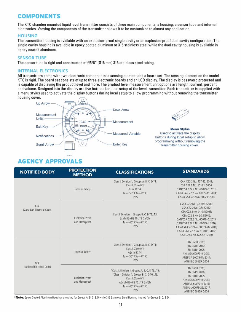
COMPONENTS The KTC chamber mounted liquid level transmitter consists of three main components: a housing, a sensor tube and internal electronics. Varying the components of the transmitter allows it to be customized to almost any application.
HOUSING The transmitter housing is available with an explosion-proof single cavity or an explosion-proof dual cavity configuration. The single cavity housing is available in epoxy coated aluminum or 316 stainless steel while the dual cavity housing is available in epoxy coated aluminum.
SENSOR TUBE The sensor tube is rigid and constructed of Ø5/8” (Ø16 mm) 316 stainless steel tubing.
INTERNAL ELECTRONICS All transmitters come with two electronic components: a sensing element and a board set. The sensing element on the model KTC is rigid. The board set consists of up to three electronic boards and an LCD display. The display is password protected and is capable of displaying the product level and more. The product level measurement unit options are length, current, percent and volume. Designed into the display are five buttons for local setup of the level transmitter. Each transmitter is supplied with a menu stylus used to activate the display buttons during local setup to allow programming without removing the transmitter housing cover.
11

MOUNTINGThe KTC magnetostrictive transmitter is mounted directly to the Kenco Magnetic Level Gauge (KMLG). The method of mounting the transmitter is dependent on the style of the magnetic level gauge. It can be installed anywhere around the perimeter of the KMLG chamber pipe that does not interfere with the gauge flag assembly or process connections. A typical installation utilizes the existing KMLG flag assembly mounting clamps. If separate mounting clamps are used, it is extremely important to ensure that they are not magnetic, as this will interfere with the magnetic field of the KMLG float. Consult Kenco for details on ordering separate mounting clamps. Before tightening the mounting clamps around the rigid sensor tube of the transmitter, allow for the minimum inactive zone at the bottom of the rigid sensor tube by placing the bottom of the sensor tube at least 2.9” (74 mm) below the centerline of bottom gauge process connection as shown above. Also, when the head of the transmitter is located above the top of the KMLG magnetic level gauge as shown above, the transmitter sensor tube can be rotated 360° to achieve the desired orientation of the transmitter housing. The transmitter may also be installed with the transmitter head at the bottom of the gauge housing. Contact Kenco for details.
TECHNICAL DRAWING KTC Magnetostrictive Transmitter mounted on Kenco Magnetic Level Gauge
12

PRODUCT SPECIFICATIONS
LEVEL OUTPUT
ELECTRONICS
SPECIFICATIONS
SPECIFICATIONS
Product levelAnalog (4-20mA) with HART® / Modbus RTU / DDA12” to 300” (305 mm to 7620 mm)±0.039” (±1 mm)0.001% F.S. or 0.015” (0.381 mm); whichever is greater
10.5 to 28 VdcLow (3.5 mA default) or High (22.8 mA)High, Full scaleSeries diodeEN 61326-1, EN 61326-2-3, EN 61326-3-2, EN 61000-6-2, EN 61000-6-3, EN 61000-4-2, EN 61000-4-3, EN 61000-4-4, EN 61000-4-5, EN 61000-4-6, EN 61000-4-8
Analog (4-20mA) with HART®Modbus RTU / DDA
Measured VariableOutput Signal / ProtocolOrder Length (Not including Inactive Zones)Inherent AccuracyRepeatability (Any Direction)
Input Voltage
Fail Safe
Reverse Polarity Protection
EMC (Electromagnetic Compatibility)
ENVIRONMENTAL SPECIFICATIONSIP650 to 100% relative humidity, non-condensing-40° F to 160° F (-40° C to 71° C)-40° F to 257° F (-40° C to 125° C); Contact factory for specific temp. ranges.316L stainless steel; Contact factory for other materials.Epoxy coated aluminum or 316 stainless steel
Enclosure Rating
Humidity
Operating Temperatures
Materials
ElectronicsSensing ElementSensor HousingElectrical Housing
ELECTRICAL HOUSING DIMENSIONS
MOUNTING CONNECTIONS
ELECTRICAL HOUSING CONNECTIONS
ELECTRICAL HOUSING LCD DISPLAY
WIRING
SPECIFICATIONS
SPECIFICATIONS
SPECIFICATIONS
SPECIFICATIONS
SPECIFICATIONS
5.7” W x 5” D x 4.3” H (145 mm W x 127 mm D x 109 mm H)4.6” W x 5” D x 8.1” H (117 mm W x 127 mm D x 206 mm H)7” W x 5.3” D x 6” H (178 mm W x 135 mm D x 152 mm H)
Existing non-magnetic stainless steel band clamps on magnetic level gauge. Separate mounting clamps can be provided. Contact factory for details.
3/4” FNPT conduit opening
Product level
4-wire shielded cable or twisted pair, Daniel Woodhead 6-pin male connector,180” (4570 mm) integral cable with pigtail
Single Cavity (Epoxy Coated Aluminum)Dual Cavity (Epoxy Coated Aluminum)Single Cavity (316 Stainless Steel)
Rigid Sensor Tube
Single and Dual Cavity
Measured Variables
Connections
13

X
S
X
To Be Determined by Kenco
1
X
KTC
B
0
Kenco Transmitter Style
KTC = Chamber Mounted
Sensor Housing
Sensor Housing
B = Rigid Ø5/8” (Ø16 mm) Tube
Digital Thermometer Quantity
0 = None
Gas Group
A = Group A (Not available with
Notified Body "C" and
Protection Method "F")
B = Group B
C = Group C
D = Group D
3 = IIC (Intrinsically Safe only)
4 = IIB+H2 (Explosion-Proof and Flameproof only)
X = None
REQUESTED BY: COMPANY:
ADDRESS: CITY: STATE: ZIP:
PHONE: FAX: EMAIL :
Electronics Mounting
7 = Top Mount
8 = Bottom Mount
Mounting Connection Size
X = None
Protection Method
F = Explosion-Proof and
Flameproof
I = Intrinsically Safe
X = No Approval
Special
S = Standard Product
Housing Type
D = Single Cavity with Display
(Epoxy Coated Aluminum)
E = Dual Cavity with Display
(Epoxy Coated Aluminum)
L = Single Cavity with Display
(316 Stainless Steel)
Mounting Connection Type
X = None
*Notified Body
C = CEC (FMC)
F = NEC (FM)
X = None
*Other certifications available
upon request.
*Order Length
XXXXX = Inches (12 to 300)
Enter Length Code as
01200 to 30000
XXXXX = mm (305 to 7620)
Enter Length Code as
00305 to 07620
*Order Length equals measurement
range plus housing clearance, but does
not include inactive zones.
Output
3 = 1 Loop with HART®
6 = 1 Loop with HART® and SIL2
M = Modbus RTU (Remote Terminal Unit)
D = DDA (Direct Digital Access)
*Sensor Housing Material
1 = 316L Stainless Steel
*Contact factory for other
available materials.
Digital Thermometer Placement
X = None
Order Length Unit of Measure
U = US Customary (Inches)
M = Metric (Millimeters)
Example Model Designation: KTC-3-D-7-B-1-X-X-0-X-X-X-X-U-01200-S
Ordering Notes: Accessories such as cables, remote displays, and separate mounting clamps can be provided, but have to be ordered separately.Contact factory for details.
ORDERING GUIDEChamber Mounted Model KTC Magnetostrictive Transmitter
14
15
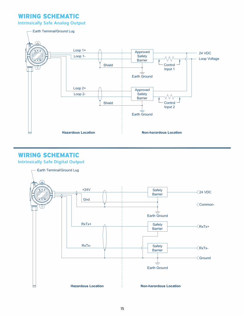
WIRING SCHEMATICIntrinsically Safe Analog Output
WIRING SCHEMATIC Intrinsically Safe Digital Output

80322 11-12-18
WIRING SCHEMATICExplosion-Proof/ Flameproof Analog Output
WIRING SCHEMATIC Explosion-Proof/ Flameproof Digital Output