The design of soil reinforced structures with thin ... · 6 MAIN ADVACE AND LIMITS OF SYSTEM 6.1...
4
Proceedings of the 23 rd European Young Geotechnical Engineers Conference, Barcelona 2014 1 The design of soil reinforced structures with thin concrete facing panels under railways V. Toth Same affiliation J. Sňahničan & J. Adamec Other affiliation ABSTRACT: The systems of polymeric reinforced soil walls with thin concrete facing panels have been well known for a few decades as a very good alternative to conventional gravity concrete walls. These systems were developed due to big demand from construction point of view, searching for ways how to reduce the cost of existing gravity retaining walls made of concrete and also to speed up the time construction. From designer point of view there was a need to tackle geotechnical problems as big size of the structure, differential settlements, earthquake loading, etc. The article talks about the invention and first tests of these structures, about design methods, system components and also about the references. 1 INTRODUCTION The modernization of a railway section between Bratislava and Kosice is one of the biggest projects in Slovakia. Due to the difficult terrain, geomorphological and environmental conditions with a limited space for construction there is a need for many geotechnical structures like tunnels, very high retaining walls and steep slopes under the railway. As a designer we were challenged to design on one hand economical solutions but on the other hand also working solutions that are the best for current application. One of the solutions for retaining walls is a system of soil reinforced wall with thin concrete facing panels. This system of reinforced soil wall is technically a very effective solution for construction of retaining walls that are going to be heavily loaded on top by railway. Especially for walls of larger scale is able to fulfill special demands for construction as the wall consists of facing precast panels which are delivered directly from precast plant along with custom designed polymer reinforcing strips. The strips placed on ground and connected with panels, afterward the backfill material can be placed over the strips. These operations can proceed quickly and cost effectively. 2 BEGIN OF SOIL REINFORCED STRUCTURES After the invent of reinforced soil wall technology in the early 60’s many different reinforcing elements and facia systems have been developed over the years to suit the requirement of retaining structures that have been built with this technology. Use of polymeric material as reinforcing elements for the reinforced soil wall began in mid 70’s. Polymeric strip “in this case was used Polymeric strip made from Polyester (PET)” is the first polymeric material that has been successfully tried and tested as reinforcing element for the reinforced soil wall. Polymeric strips consist of high tenacity polyester core encased in polyethylene outer sheath. The width of Polymeric strip varied between 85 to 90mm depending on the strength of strip. Apart from retaining the sides of approaches to bridges, grade separators, wing walls for road projects, polymeric reinforced soil wall has been used to build variety of retaining structures, due to the inherent simplicity, flexibility and speed of construction of the system. In this paper polymeric reinforced soil wall system has been briefly described and case studies have been presented describing the use of this system to construct retaining walls for different structures. 3 TESTS IN SCALE 1:1 The impetus for the use of Polymeric as reinforcing element in reinforced soil wall came in the UK in the mid 70’s as an alternative to the corrodible steel strips which formed the basis of the patented French and was led by the Government’s Transport Research Laboratory. Polyester strip for use in this application was one such development but, unlike most others, it has stood the test of time. Figure 1. (a) Elevation of TRL experimental Wall with polymer reinforcement ParaWeb, Sample exhumed March 2005 (b) before removal, (c) after removal. The first polyester “in this case was used ParaWeb” wall structure was built by the Transport Research Laboratory at its Crowthorne facility in 1977. Samples are still taken periodically for test to demonstrate the long-term performance characteristics of the material. Figure 1(a) shows the elevation of TRL wall where polymeric strip was used as reinforcing elements. Figure 1(b) shows the polymeric strip “ParaWeb” exhumed from the wall in 2005. The mean stress strain relationship indicates that no significant reduction in mean
Transcript of The design of soil reinforced structures with thin ... · 6 MAIN ADVACE AND LIMITS OF SYSTEM 6.1...
Proceedings of the 23rdEuropean Young Geotechnical Engineers Conference, Barcelona 2014
1
The design of soil reinforced structures with thin concrete facing panels under railways
V. Toth Same affiliation
J. Sňahničan & J. Adamec Other affiliation
ABSTRACT: The systems of polymeric reinforced soil walls with thin concrete facing panels have been well known for a few decades as a very good alternative to conventional gravity concrete walls. These systems were developed due to big demand from construction point of view, searching for ways how to reduce the cost of existing gravity retaining walls made of concrete and also to speed up the time construction. From designer point of view there was a need to tackle geotechnical problems as big size of the structure, differential settlements, earthquake loading, etc. The article talks about the invention and first tests of these structures, about design methods, system components and also about the references.
1 INTRODUCTION
The modernization of a railway section between Bratislava and Kosice is one of the biggest projects in Slovakia. Due to the difficult terrain, geomorphological and environmental conditions with a limited space for construction there is a need for many geotechnical structures like tunnels, very high retaining walls and steep slopes under the railway. As a designer we were challenged to design on one hand economical solutions but on the other hand also working solutions that are the best for current application.
One of the solutions for retaining walls is a system of soil reinforced wall with thin concrete facing panels. This system of reinforced soil wall is technically a very effective solution for construction of retaining walls that are going to be heavily loaded on top by railway. Especially for walls of larger scale is able to fulfill special demands for construction as the wall consists of facing precast panels which are delivered directly from precast plant along with custom designed polymer reinforcing strips. The strips placed on ground and connected with panels, afterward the backfill material can be placed over the strips. These operations can proceed quickly and cost effectively.
2 BEGIN OF SOIL REINFORCED STRUCTURES
After the invent of reinforced soil wall technology in the early 60’s many different reinforcing elements and facia systems have been developed over the years to suit the requirement of retaining structures that have been built with this technology. Use of polymeric material as reinforcing elements for the reinforced soil wall began in mid 70’s. Polymeric strip “in this case was used Polymeric strip made from Polyester (PET)” is the first polymeric material that has been successfully tried and tested as reinforcing element for the reinforced soil wall. Polymeric strips consist of high tenacity polyester core encased in polyethylene outer sheath. The width of Polymeric strip varied between 85 to 90mm depending on the strength of strip. Apart from retaining the sides of approaches to bridges, grade separators, wing walls for road projects, polymeric reinforced soil wall has been used to build variety of retaining structures,
due to the inherent simplicity, flexibility and speed of construction of the system. In this paper polymeric reinforced soil wall system has been briefly described and case studies have been presented describing the use of this system to construct retaining walls for different structures.
3 TESTS IN SCALE 1:1
The impetus for the use of Polymeric as reinforcing element in reinforced soil wall came in the UK in the mid 70’s as an alternative to the corrodible steel strips which formed the basis of the patented French and was led by the Government’s Transport Research Laboratory. Polyester strip for use in this application was one such development but, unlike most others, it has stood the test of time.
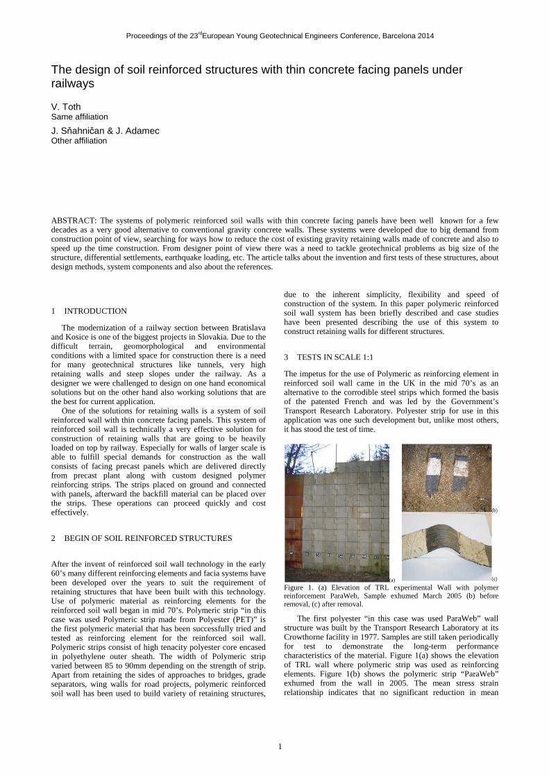
Figure 1. (a) Elevation of TRL experimental Wall with polymer reinforcement ParaWeb, Sample exhumed March 2005 (b) before removal, (c) after removal.
The first polyester “in this case was used ParaWeb” wall structure was built by the Transport Research Laboratory at its Crowthorne facility in 1977. Samples are still taken periodically for test to demonstrate the long-term performance characteristics of the material. Figure 1(a) shows the elevation of TRL wall where polymeric strip was used as reinforcing elements. Figure 1(b) shows the polymeric strip “ParaWeb” exhumed from the wall in 2005. The mean stress strain relationship indicates that no significant reduction in mean
Proceedings of the 23rdEuropean Young Geotechnical Engineers Conference, Barcelona 2014
2
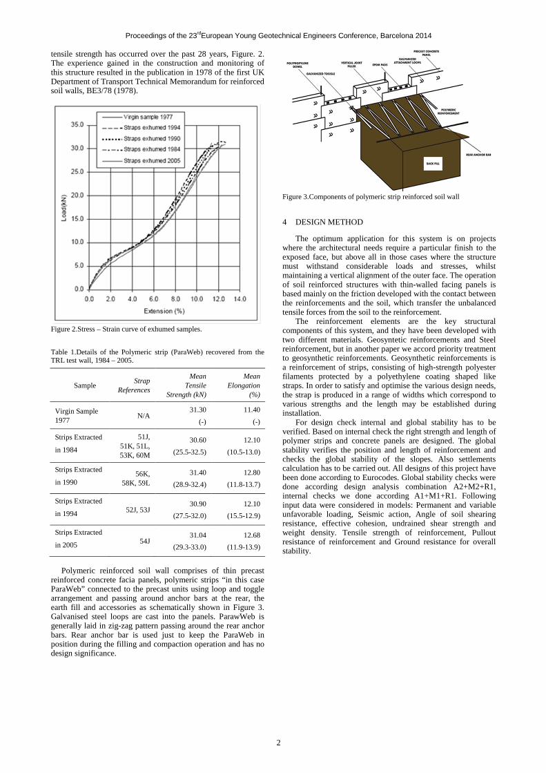
tensile strength has occurred over the past 28 years, Figure. 2. The experience gained in the construction and monitoring of this structure resulted in the publication in 1978 of the first UK Department of Transport Technical Memorandum for reinforced soil walls, BE3/78 (1978).
Figure 2.Stress – Strain curve of exhumed samples.
Table 1.Details of the Polymeric strip (ParaWeb) recovered from the TRL test wall, 1984 – 2005.
Sample Strap
References
Mean Tensile
Strength (kN)
Mean Elongation
(%)
Virgin Sample 1977
N/A 31.30
(-)
11.40
(-)
Strips Extracted
in 1984
51J, 51K, 51L, 53K, 60M
30.60
(25.5-32.5)
12.10
(10.5-13.0)
Strips Extracted
in 1990 56K,
58K, 59L
31.40
(28.9-32.4)
12.80
(11.8-13.7)
Strips Extracted
in 1994 52J, 53J 30.90
(27.5-32.0)
12.10
(15.5-12.9)
Strips Extracted
in 2005 54J 31.04
(29.3-33.0)
12.68
(11.9-13.9)
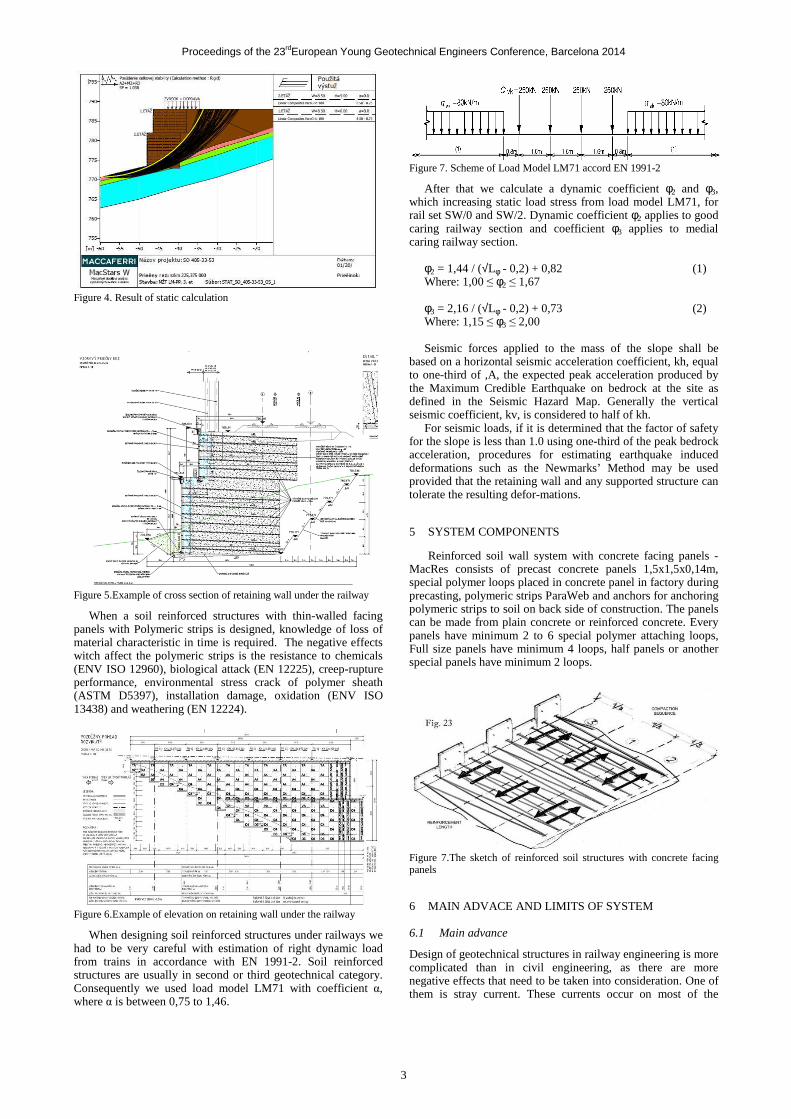
Polymeric reinforced soil wall comprises of thin precast
reinforced concrete facia panels, polymeric strips “in this case ParaWeb” connected to the precast units using loop and toggle arrangement and passing around anchor bars at the rear, the earth fill and accessories as schematically shown in Figure 3. Galvanised steel loops are cast into the panels. ParawWeb is generally laid in zig-zag pattern passing around the rear anchor bars. Rear anchor bar is used just to keep the ParaWeb in position during the filling and compaction operation and has no design significance.
Figure 3.Components of polymeric strip reinforced soil wall
4 DESIGN METHOD
The optimum application for this system is on projects where the architectural needs require a particular finish to the exposed face, but above all in those cases where the structure must withstand considerable loads and stresses, whilst maintaining a vertical alignment of the outer face. The operation of soil reinforced structures with thin-walled facing panels is based mainly on the friction developed with the contact between the reinforcements and the soil, which transfer the unbalanced tensile forces from the soil to the reinforcement. The reinforcement elements are the key structural components of this system, and they have been developed with two different materials. Geosyntetic reinforcements and Steel reinforcement, but in another paper we accord priority treatment to geosynthetic reinforcements. Geosynthetic reinforcements is a reinforcement of strips, consisting of high-strength polyester filaments protected by a polyethylene coating shaped like straps. In order to satisfy and optimise the various design needs, the strap is produced in a range of widths which correspond to various strengths and the length may be established during installation.
For design check internal and global stability has to be verified. Based on internal check the right strength and length of polymer strips and concrete panels are designed. The global stability verifies the position and length of reinforcement and checks the global stability of the slopes. Also settlements calculation has to be carried out. All designs of this project have been done according to Eurocodes. Global stability checks were done according design analysis combination A2+M2+R1, internal checks we done according A1+M1+R1. Following input data were considered in models: Permanent and variable unfavorable loading, Seismic action, Angle of soil shearing resistance, effective cohesion, undrained shear strength and weight density. Tensile strength of reinforcement, Pullout resistance of reinforcement and Ground resistance for overall stability.
Proceedings of the 23rdEuropean Young Geotechnical Engineers Conference, Barcelona 2014
3
Figure 4. Result of static calculation
Figure 5.Example of cross section of retaining wall under the railway
When a soil reinforced structures with thin-walled facing panels with Polymeric strips is designed, knowledge of loss of material characteristic in time is required. The negative effects witch affect the polymeric strips is the resistance to chemicals (ENV ISO 12960), biological attack (EN 12225), creep-rupture performance, environmental stress crack of polymer sheath (ASTM D5397), installation damage, oxidation (ENV ISO 13438) and weathering (EN 12224).
Figure 6.Example of elevation on retaining wall under the railway
When designing soil reinforced structures under railways we had to be very careful with estimation of right dynamic load from trains in accordance with EN 1991-2. Soil reinforced structures are usually in second or third geotechnical category. Consequently we used load model LM71 with coefficient α, where α is between 0,75 to 1,46.
Figure 7. Scheme of Load Model LM71 accord EN 1991-2
After that we calculate a dynamic coefficient φ2 and φ3, which increasing static load stress from load model LM71, for rail set SW/0 and SW/2. Dynamic coefficient φ2 applies to good caring railway section and coefficient φ3 applies to medial caring railway section.
φ2 = 1,44 / (√Lφ - 0,2) + 0,82 (1) Where: 1,00 ≤ φ2 ≤ 1,67 φ3 = 2,16 / (√Lφ - 0,2) + 0,73 (2) Where: 1,15 ≤ φ3 ≤ 2,00 Seismic forces applied to the mass of the slope shall be
based on a horizontal seismic acceleration coefficient, kh, equal to one-third of ,A, the expected peak acceleration produced by the Maximum Credible Earthquake on bedrock at the site as defined in the Seismic Hazard Map. Generally the vertical seismic coefficient, kv, is considered to half of kh.
For seismic loads, if it is determined that the factor of safety for the slope is less than 1.0 using one-third of the peak bedrock acceleration, procedures for estimating earthquake induced deformations such as the Newmarks’ Method may be used provided that the retaining wall and any supported structure can tolerate the resulting defor-mations.
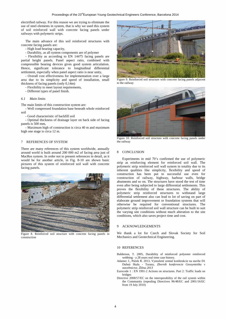
5 SYSTEM COMPONENTS
Reinforced soil wall system with concrete facing panels - MacRes consists of precast concrete panels 1,5x1,5x0,14m, special polymer loops placed in concrete panel in factory during precasting, polymeric strips ParaWeb and anchors for anchoring polymeric strips to soil on back side of construction. The panels can be made from plain concrete or reinforced concrete. Every panels have minimum 2 to 6 special polymer attaching loops, Full size panels have minimum 4 loops, half panels or another special panels have minimum 2 loops.
Figure 7.The sketch of reinforced soil structures with concrete facing panels
6 MAIN ADVACE AND LIMITS OF SYSTEM
6.1 Main advance
Design of geotechnical structures in railway engineering is more complicated than in civil engineering, as there are more negative effects that need to be taken into consideration. One of them is stray current. These currents occur on most of the
Proceedings of the 23rdEuropean Young Geotechnical Engineers Conference, Barcelona 2014
4
electrified railway. For this reason we are trying to eliminate the use of steel elements in system, that is why we used this system of soil reinforced wall with concrete facing panels under railways with polymeric strips.
The main advance of this soil reinforced structures with
concrete facing panels are: - High load bearing capacity, - Durability, as all system components are of polymer - Flexibility as according to EN 14475 facing panels are
partial height panels. Panel aspect ratio, combined with compressible bearing devices gives good system articulation. Hence, significant tolerance to longitudinal differential settlement, especially when panel aspect ratio is near unity,
- Overall cost effectiveness for implementation over a large area due to its simplicity and speed of installation, small thickness of facing panels (only 0,14m)
- Flexibility to meet layout requirements, - Different types of panel finish.
6.1 Main limits
The main limits of this construction system are: - Well compressed foundation base beneath whole reinforced
soil - Good characteristic of backfill soil - Optimal thickness of drainage layer on back side of facing
panels is 500 mm, - Maximum high of construction is circa 40 m and maximum
high one stage is circa 12 m.
7 REFERENCES OF SYSTEM
There are many references of this system worldwide, annually around world is built around 200 000 m2 of facing area just of MacRes system. In order not to present references in detail, as it would be for another article, in Fig. 8-10 are shown basic pictures of this system of reinforced soil wall with concrete facing panels.
Figure 8. Reinforced soil structure with concrete facing panels in construction
Figure 9. Reinforced soil structure with concrete facing panels adjacent to the railway
Figure 10. Reinforced soil structure with concrete facing panels under the railway
8 CONCLUSION
Experiments in mid 70’s confirmed the use of polymeric strip as reinforcing element for reinforced soil wall. The polymeric strip reinforced soil wall system in totality due to its inherent qualities like simplicity, flexibility and speed of construction has been put to successful use even for construction of railway, highway, harbour walls, bridge abutments and so on. The structures have stood the test of time even after being subjected to large differential settlements. This proves the flexibility of these structures. The ability of polymeric strip reinforced structures to withstand large differential settlement also can lead to lot of saving on part of elaborate ground improvement or foundation systems that will otherwise be required for conventional structures. The polymeric strip reinforced soil wall structure can be built to suit the varying site conditions without much alteration to the site conditions, which also saves project time and cost.
9 ACKNOWLEDGEMENTS
We thank a lot for Czech and Slovak Society for Soil Mechanics and Geotechnical Engineering.
10 REFERENCES
Balderson, T. 2005, Durability of reinforced polyester reinforced webbing - a 28 years real time case history.
Adamec J., Púček R. 2013, Vystužené zemné konštrukcie na stavbe D1 Dubná Skala - Turany, Zborník konferencie Geosyntetika v stavebníctve, Žilina 2013
Eurocode 1 : EN 1991-2 Actions on structures. Part 2: Traffic loads on bridges
Directive 2008/57/EC on the interoperability of the rail system within the Community (repealing Directives 96/48/EC and 2001/16/EC from 19 July 2010)