The Design of Reinforced Earth Walls DGS 28-11-2013...Danish Geotechnical Society Seminar on...
32
Danish Geotechnical Society Seminar on Reinforced Earth – 28/11/2013 The Design of Reinforced Earth Walls Jérémy PLANCQ – Design Engineer, Terre Armée France
Transcript of The Design of Reinforced Earth Walls DGS 28-11-2013...Danish Geotechnical Society Seminar on...

Danish Geotechnical Society Seminar on Reinforced Earth – 28/11/2013
The Design of Reinforced Earth WallsJérémy PLANCQ – Design Engineer, Terre Armée France

Danish Geotechnical Society Seminar on Reinforced Earth – 28/11/2013
Fundamental Mechanisms
The Reinforced Earth is a composite material with an anisotropic artificial cohesion
Layers of pebbles separated by sheets of cardboard: The friction of the pebbles on the
cardboard And the resistance of the cardboard
sheets to traction Make it possible to build a “stack”
The reinforcements (cardboard sheets) act as a binding

Danish Geotechnical Society Seminar on Reinforced Earth – 28/11/2013
Fundamental Mechanisms
If a confined dry sand, subject to confining stress 3 is loaded with a vertical stress 1 it will undergo an axial compression v and a lateral expansion h/2
If several layers of reinforcement are inserted into the soil, the magnitude of these deformations will reduce
This is a result of the confining stress generated by an interaction between the soil and the reinforcement
The factors involved define the basic principles of reinforced soil

Danish Geotechnical Society Seminar on Reinforced Earth – 28/11/2013
Fundamental Mechanisms
When an vertical load is applied to reinforced soil this generates a vertical compressive strain and a resulting lateral tensile strain
If the tensile stiffness of the reinforcement is greater than that of the soil, movement will only occur if the soil can move relative to the reinforcement
Provided the surface of the soil reinforcement is sufficiently rough, movement of the soil, relative to the reinforcement, will generate shear stresses at the soil/reinforcement interface (soil/structure interaction)
These shear stresses induce tensile loads in the reinforcement which are redistributed back into the soil in the form of an internal confining stress
T T+dT
dL
σv
Danish Geotechnical Society Seminar on Reinforced Earth – 28/11/2013
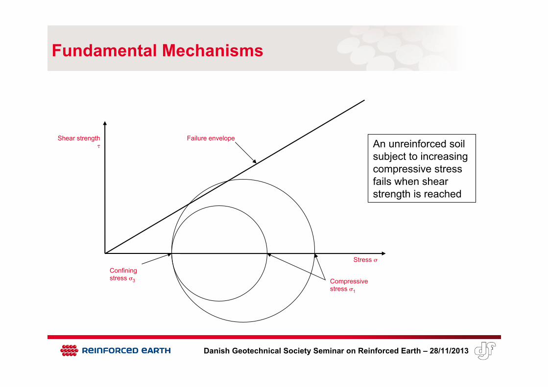
Fundamental Mechanisms
Shear strength
Stress Confining stress 3 Compressive
stress 1
Failure envelopeAn unreinforced soil subject to increasing compressive stress fails when shear strength is reached

Danish Geotechnical Society Seminar on Reinforced Earth – 28/11/2013
Fundamental Mechanisms
When a soil is reinforced, increased compressive stress leads to increase in confining stressPractical limit is imposed on reinforced soil by tensile rupture of soil reinforcement or loss of adherence strength
Shear strength
Stress
Confining stress 3 Compressive
stress 1
Failure envelope

Danish Geotechnical Society Seminar on Reinforced Earth – 28/11/2013
Fundamental Mechanisms
The internal friction makes it possible to space out the reinforcements Arch effect
A facing linked to the reinforcements is needed for: Local stability of the fill between two
reinforcements Protection against erosion
The facing is NOT there to take all applied load at the back (earth pressure, live loads) as for common CIP concrete walls

Danish Geotechnical Society Seminar on Reinforced Earth – 28/11/2013
Behaviour of Reinforced Earth
The first structures were designed very simply
A research program was launched in 1969
Scale models Small models (bidimensional, three-
dimensional) for study of failure modes Bigger models (≥ 1m) for measurement of
stresses
Danish Geotechnical Society Seminar on Reinforced Earth – 28/11/2013
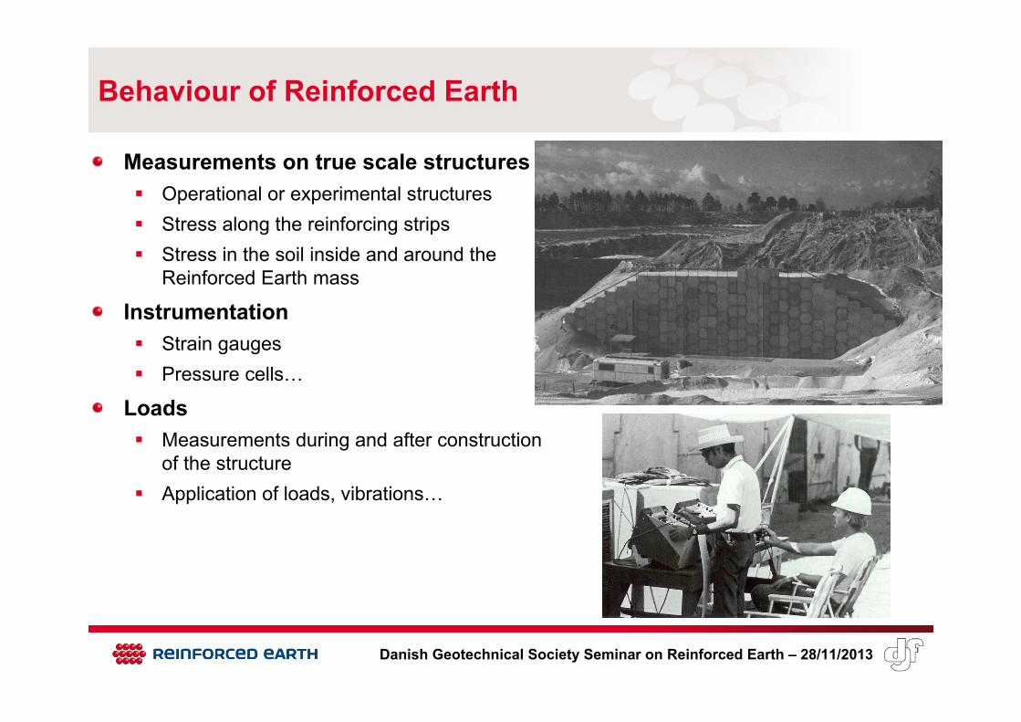
Behaviour of Reinforced Earth
Measurements on true scale structures Operational or experimental structures Stress along the reinforcing strips Stress in the soil inside and around the
Reinforced Earth mass
Instrumentation Strain gauges Pressure cells…
Loads Measurements during and after construction
of the structure Application of loads, vibrations…

Danish Geotechnical Society Seminar on Reinforced Earth – 28/11/2013
Experimental structures
Milville, USA, 1970’sFremersdorf, Germany, 1980Fontainebleau, France, 1988: 6m high + beam Vertical and horizontal loadings applied by cables jacked and tied-back 129 tensile points 31 Glötzl cells to measure vertical stress horizontal inclinometers

Danish Geotechnical Society Seminar on Reinforced Earth – 28/11/2013
Experimental structures
Fontainebleau, France, 1988
Incremental tension in the strips (for Qv=2025kN to Qv=4050kN)

Danish Geotechnical Society Seminar on Reinforced Earth – 28/11/2013
Behaviour of Reinforced Earth
Finite elements modelsSofware Rosalie (LCPC) 1982-85 50 models of walls 50 models of true abutments Parameters :
height, slenderness, shape, loads, reinforcements distribution, type of facing, deformation modulus of the subsoil…
Software Superflush (EET, USA) Walls subjected to seismic loadings
This research program led to the current semi-empirical method for the design of Reinforced Earth
Null distance
Null distance
STRIP TENSION AS A FUNCTION OF DEPTH
TENSION ALONG THE STRIPS
STRIP LAYER n°3
STRIP LAYER n°6

Danish Geotechnical Society Seminar on Reinforced Earth – 28/11/2013
Evolution of Design Standards
1973: Technical Note LCPC : “La Terre Armée”1979: Guide from French National Road Administration: “Recommendations and good practice for Reinforced Earth structures”1992/1998: French standard NF P 94-220 “Soil reinforcement – Backfilled structures with quasi-inextensible and flexible reinforcing strips or sheets”
Up-to-date standard: NF P 94-270:2009 “Geotechnical design – Retaining structures – Reinforced and soil nailing structures”, French national application standard for Reinforced Earth structures derived from Eurocode 7
I addition, European standard for execution of special geotechnical works for reinforced fill: EN 14475:2006
Specific standards for Reinforced Earth also exist in other countries: Germany, UK (British Standard), USA (AASHTO), Japan, Australia…
Danish Geotechnical Society Seminar on Reinforced Earth – 28/11/2013
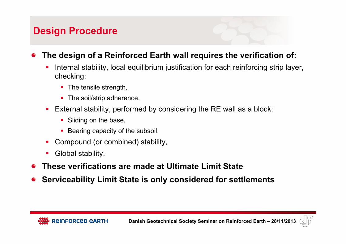
Design Procedure
The design of a Reinforced Earth wall requires the verification of: Internal stability, local equilibrium justification for each reinforcing strip layer,
checking: The tensile strength, The soil/strip adherence.
External stability, performed by considering the RE wall as a block: Sliding on the base, Bearing capacity of the subsoil.
Compound (or combined) stability, Global stability.
These verifications are made at Ultimate Limit StateServiceability Limit State is only considered for settlements

Danish Geotechnical Society Seminar on Reinforced Earth – 28/11/2013
Design Approach 2
Approach 2 is used for internal and external stability verificationsElementary actions (weight and earth pressure) Calculated with characteristic values γk , φ’k and c’k Then weighted
Rv
Load case 1(max. tension)
Load case 2(min. adherence)
W 1.35 1.00
P 1.35 1.35
Q1 1.50 -
Q2 / Pq 1.50 1.50
W
P
Pq
Q1
φ1’
φ3’ c3’ or cu3
φ2’
Q2

Danish Geotechnical Society Seminar on Reinforced Earth – 28/11/2013
Design Approach 3
Approach 3 is used for compound and global stability verificationsSoil parameters Reduced
Permanent actions Not weighted: γG = 1.0
Variable actions Weighted: γQ = 1.3
Rv
q
φ1’
φ3’ c3’ ou cu3
φ2’
γφ’ 1.25
γ c’ 1.25
γ cu 1.40

Danish Geotechnical Society Seminar on Reinforced Earth – 28/11/2013
External stability (approach 2)
Similar to standard retaining wallsSliding on the base: Horizontal resultant Hd must be compatible
with: Maximum allowable frictional resistance inside
RE fill under vertical resultant Vd (function of φ1k) Maximum allowable frictional resistance in
foundation soil under vertical resultant Vd(function of φfk, cfk on width L)
Partial safety factor on resistance: γR;h = 1.1
Hd
Vd φ1k
φfk, cfk
L

Danish Geotechnical Society Seminar on Reinforced Earth – 28/11/2013
External stability (approach 2)
Bearing capacity of foundation soil: Vertical resultant Vd, spread on reduced
width 2x (Meyerhof’s model) must be compatible with the bearing capacity of the foundation soil on this reduced width
Partial safety factor on resistance: γR;v = 1.4
Rv
x
Vd

Danish Geotechnical Society Seminar on Reinforced Earth – 28/11/2013
Embedment depth
The embedment depth D at the foot of a Reinforced Earth wall is a function of the pressure at the base of the wall (qref) and of the angle of the slope at the bottom of the wall (βp), with a minimum value of 0.4m (except on rock or concrete):
Slope βp of ground in front
D/qref(m/kPa)
0 1.5 x 10⁻³
18° (tan βp = 1/3) 3.0 x 10⁻³
27° (tan βp = 1/2) 4.5 x 10⁻³
34° (tan βp = 2/3) 6.4 x 10⁻³

Danish Geotechnical Society Seminar on Reinforced Earth – 28/11/2013
Internal stability (approach 2)
Semi-empirical method
Maximum tension line Linking the points where tension in the strips
reaches its maximum Boundary between “active zone” and
“resistant zone” Line defined by the sketch, for standard
shape of RE wall Usually 0.5 Hm ≤ L ≤ 0.7 Hm
0.2Hm
0.3Hm
0.6Hm
0.4Hm
L
tm

Danish Geotechnical Society Seminar on Reinforced Earth – 28/11/2013
Internal stability (approach 2)
Maximum tension tm In the strips with vertical spacing sv, on
which applies horizontal stress σh:
On maximum tension line, σh and σv are linked by:
At each strip level, σv is calculated as for the pressure at the base
For reinforcing strips z ≥ 6m K = Ka
z < 6m Ka ≤ K ≤ 1.6 Ka
z
K1.6Ka
Ka
6m
sv
tmvh K σσ ⋅=
vhm st ⋅= σ
φ1k
−=
24tan 12 k
aKϕπ

Danish Geotechnical Society Seminar on Reinforced Earth – 28/11/2013
Internal stability (approach 2)
Allowable tensile strength Maximum tension tm must be lower than the
long term allowable tensile strength of the strip layer Allowable tensile strength is calculated
considering the required service life of the structure
Partial safety factor: 1.00 on yield stress (steel reinforcements) 1.25 on tensile failure
vhm st ∗σ=
Rv
x2x
σv

Danish Geotechnical Society Seminar on Reinforced Earth – 28/11/2013
Allowable tensile strength
The allowable tensile strength for one strip (Tr) is given by:
where: Tlim: initial ultimate tensile strength (respectively yield strength) of the strip, ρend: reduction factor due to installation damage (= 1 for steel strips), ρflu: reduction factor due to creep (= 1 for steel strips), ρdeg: reduction factor due to environmental chemical and biological degradation. For
steel strips, this factor represents the loss of strength due to the loss of thickness with time.
γM;t = 1.25 (resp. 1.00): partial safety coefficient on ultimate (resp. yield) tensile limit of the strip material.
Calculation of ρdeg for steel strips is detailed in NF P 94-270 standardReduction factors for geosynthetic strips are derived from laboratory tests
tMfluendr
TT;
limdeg γ
ρρρ ⋅⋅⋅=

Danish Geotechnical Society Seminar on Reinforced Earth – 28/11/2013
Internal stability (approach 2)
Tension at the facing The tension in one strip at the facing is equal to:
t0 = αi.tm where αi is given by:
Full height rigidfacing
Z
0.75
1.00 αi
Z0.
85
0.4H
1.00 αi
Z
1.00 αi
Flexiblefacing
Concretepanels

Danish Geotechnical Society Seminar on Reinforced Earth – 28/11/2013
Internal stability (approach 2)
Pull-out capacity (soil/strip adherence) The strips are anchored in the resistant zone The pull-out capacity (rf) is a function of:
Adherence length La
Total horizontal surface of the strips (nb2) n strips of b width on 2 faces on 1m
Average vertical stress (σv) along La
Friction coefficient µ*
La
σv

Danish Geotechnical Society Seminar on Reinforced Earth – 28/11/2013
La
ha
Internal stability (approach 2)
Soil/strip adherence The friction coefficient µ* depends on the
type of reinforcement High adherence (HA) or smooth steel strips Welded mesh Geosynthetic strips
µ* is derived from pull-out tests
For HA steel strips, µ* varies with the average depth (ha) on the adherence length La
ha ≥ 6m ha < 6m
with
(function of the fill characteristics)
φ1k
h
µ*
µ0*
µ1*
6m
k11 tanϕ=μ=μ ∗∗
∗∗∗ μ≤μ<μ 01
5.22.1 0 << ∗μ

Danish Geotechnical Society Seminar on Reinforced Earth – 28/11/2013
Friction coefficient
Experimental measurements Pull-out tests of strip samples:
Experimental or operational structures Laboratory device
Database for various types of strips, fills (grain size distribution), depths…
Conservative envelope
PRESSUREMETER
JACK
SUPPORT
STRIP SAMPLE
HA
Smooth
µ*Influence of type of strip
HA
Smooth
µ* Influence of earth pressure

Danish Geotechnical Society Seminar on Reinforced Earth – 28/11/2013
Friction coefficient
Dilatancy of soils Increase in volume of a compacted granular material
subjected to shear
The dilatancy effect: Increases with the density, i.e. the compacity Decreases with the increase of confining stress At low depth, the “impeded dilatancy” leads to a local
increase of the vertical stress and to an increase of the apparent friction coefficient
h
µ*
µ0*
µ1*
6m
strips
Real σv
γh

Danish Geotechnical Society Seminar on Reinforced Earth – 28/11/2013
Internal stability (approach 2)
Pull-out capacity Maximum tension tm must be lower than
pull-out capacity rf
Partial safety factor: 1.35
h
µ*
µ0*
µ1*
6m
La
ha
σv
φ1k

Danish Geotechnical Society Seminar on Reinforced Earth – 28/11/2013
Compound stability (approach 3)
Checking of structure stability along potential failure surfaces which are crossing the reinforcing strip layers
Partial factor on global shear resistance: 1.1Partial factors on reinforcements: Tensile strength :
1.00 on yield stress 1.25 on tensile failure
Adherence : 1.10

Danish Geotechnical Society Seminar on Reinforced Earth – 28/11/2013
Global stability (approach 3)
Checking of structure stability along potential failure surfaces which are not crossing the reinforcing strip layers
Partial factor on global shear resistance: 1.1

Danish Geotechnical Society Seminar on Reinforced Earth – 28/11/2013
Thank you !