
THE DESIGN OF BRUSHES FOR THE HOMOPOLAR · PDF fileTHE DESIGN OF BRUSHES FOR THE HOMOPOLAR...
52
THE DESIGN OF BRUSHES FOR THE HOMOPOLAR GENERATOR AT THE AUSTRALIAN NATIONAL UNIVERSITY A. STEBBENS H. WARD First Published: March, 1964 Re-issued: September, 1967 Department of Engineering Physics Research School of Physical Sciences THE AUSTRALIAN NATIONAL UNIVERSITY berra, A.C.T., Australia. HANCOCK large book T J 163 . A87 ep - rrib TJ163.A87 EP-RR18. 1924140 A.N.U. LIBRARY
Transcript of THE DESIGN OF BRUSHES FOR THE HOMOPOLAR · PDF fileTHE DESIGN OF BRUSHES FOR THE HOMOPOLAR...
THE DESIGN OF BRUSHES FOR THE HOMOPOLAR GENERATOR AT THE
AUSTRALIAN NATIONAL
UNIVERSITY
A. STEBBENS H. WARD
First Published: March, 1964
Re-issued: September, 1967
Department of Engineering Physics
Research School of Physical Sciences
THE AUSTRALIAN NATIONAL UNIVERSITY
berra, A.C.T., Australia.
HANCOCK l a r g e b o o k T J 1 6 3 . A 8 7
e p - r r i b
TJ163.A87 EP-RR18.1 9 2 4 1 4 0
A.N.U. LIBRARY

This book was published by ANU Press between 1965–1991.
This republication is part of the digitisation project being carried out by Scholarly Information Services/Library and ANU Press.
This project aims to make past scholarly works published by The Australian National University available to
a global audience under its open-access policy.
THE DESIGN OF BRUSHES FOR THE HOMOPOLAR
GENERATOR AT THE AUSTRALIAN NATIONAL UNIVERSITY
(M organite R esearch and Development, Limited)
(Consultants to The A ustralian National University)
F ir s t Published: M arch, 1964 R e-issued : Septem ber, 1967
Publication EP-R R 18
D epartm ent of Engineering Physics R esearch School of Physical Sciences
THE AUSTRALIAN NATIONAL UNIVERSITY
C anberra, A . C . T . A ustra lia
by
A. STEBBENS
H. WARD
(M organite Carbon, Limited)

- 6 FEB 1968

C O N T E N T S
FOREWORD
1. Introduction
2. T erm s of R eference fo r B rush Consultants
3. Conditions under Which B rushes O perate
3 .1 G eneral
3. 2 Com parison with Norm al Conditions
4. Experim ental P rogram m e C arried Out by M organite at London
5. Experim ental P rogram m e at C anberra
6. B rush H olders
6 .1 R otor Rim B rushes
6. 2 Top and Bottom Inner B rushes
6. 3 Mid Inner B rushes
7. Magnetic, E lec trica l and T herm al Effects
7 .1 Interaction of Magnetic Fields and C urren ts in B rushgear
7 .2 Voltage G radients
7 .3 Therm al loading of R otors and Slip-rings
8. M aintenance
9. Conclusions
9.1 Design and P erfo rm ance D etails
9. 2 P rac ticab ility of C u rren t Collection with B rushes
10. R eferences
i

ACKNOWLEDGEMENTS
We wish to acknowledge the helpful co-operation received from P ro fe sso r S ir M ark Oliphant and all the m em bers of his staff, p articu la rly Mr. R. A. M arshall, during our stay a t C anberra .
SUMMARY
The authors w ere invited by The A ustralian National U niversity to v isit C anberra in o rd e r to advise on the p rac ticab ility of using brushes fo r cu rren t co llection on the very la rg e hom opolar generato r under construction at the R esearch School of Physical Sciences.
Experim ental program m es w ere organised both at London and C anberra in o rd e r to evaluate various brush grades for the abnorm al conditions associated with this application; as a resu lt it was shown that the copper-graphite grade CM1S would operate under the requ ired conditions of speed, cu rren t density and load and this grade was th e re fo re chosen for initial tr ia ls on the generato r.
We have considered in detail the proposals by the University for b ru sh g ear design, and the conditions of brush operation. We conclude that therm al s tre s s of the ro to r is a m ajo r problem at the ra ted output of the generato r. Much fu rth er work on b rushgear design and the effects of magnetic fo rces is requ ired before the use of b rushes can be said, with confidence, to be practicab le .
ii
F O R E W O R D
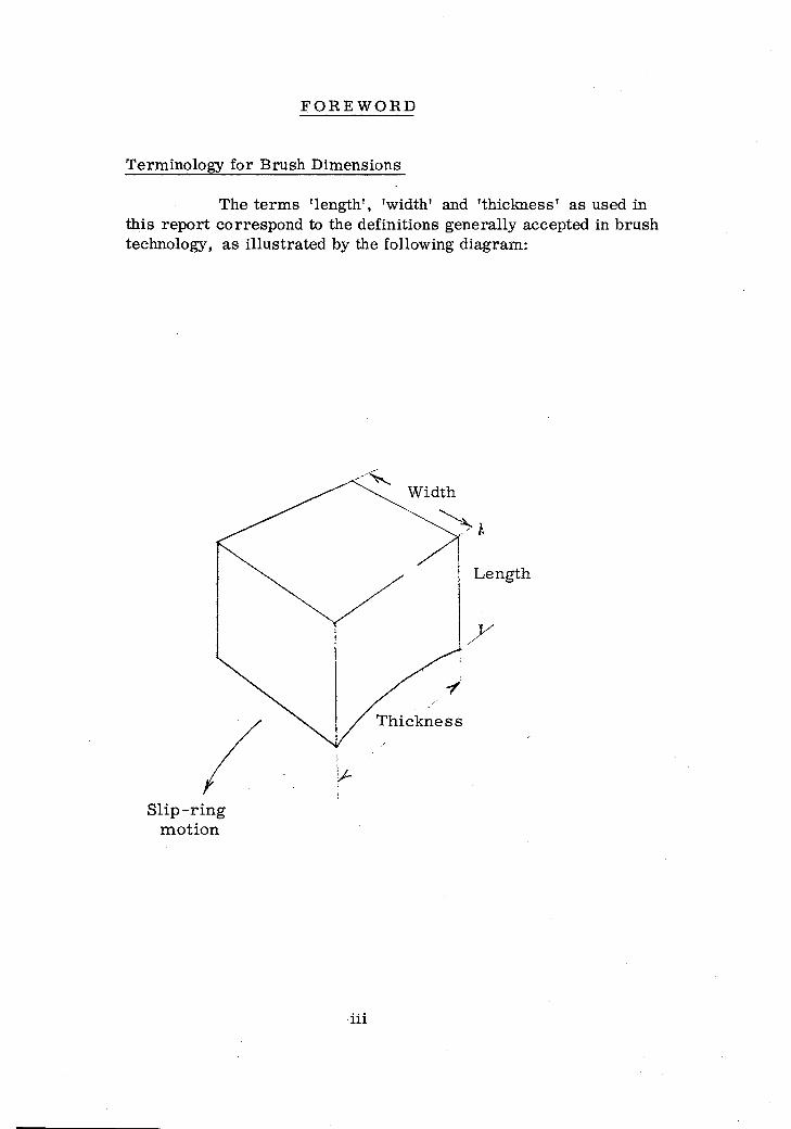
Term inology for B rush Dim ensions
The te rm s 'leng th ', ’width' and 'th ickness ' as used in th is rep o rt correspond to the definitions generally accepted in brush technology, as illu s tra ted by the following diagram :
S l ip - r in g m o tio n
iii
1 . Introduction
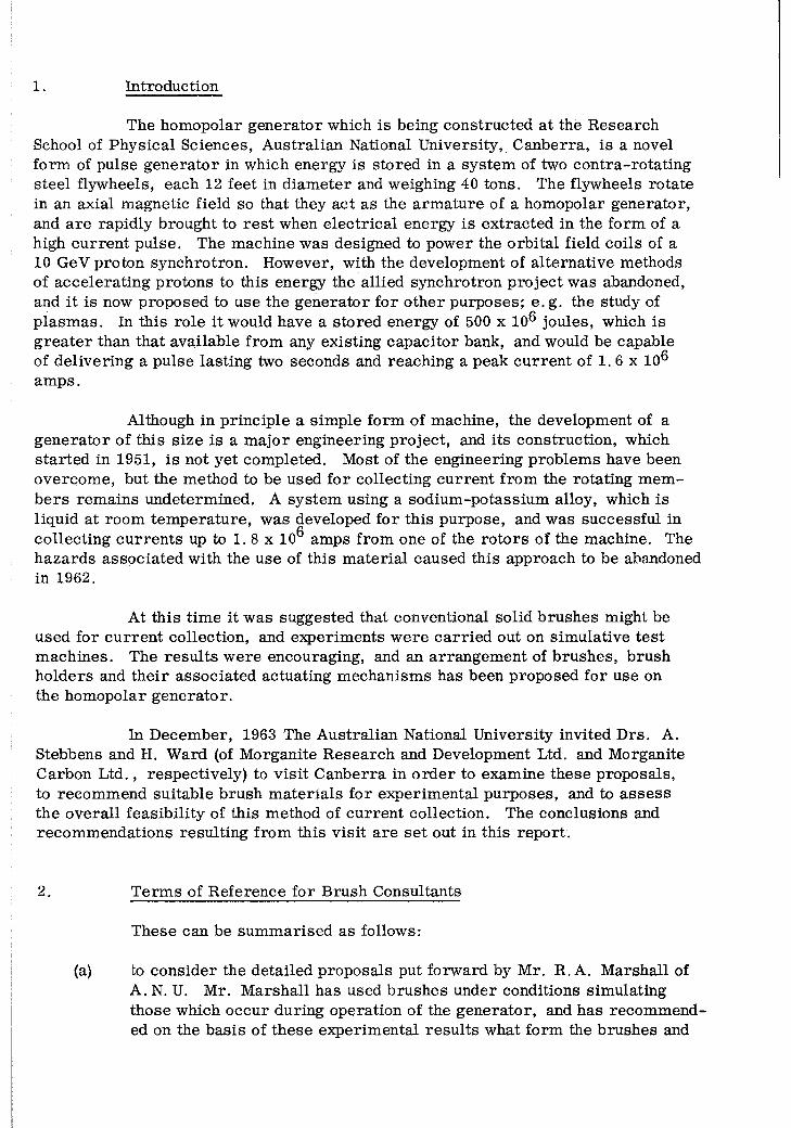
The hom opolar generato r which is being constructed at the R esearch School of Physical Sciences, A ustralian National University, C anberra, is a novel form of pulse g enera to r in which energy is stored in a system of two con tra-ro ta ting steel flywheels, each 12 feet in d iam eter and weighing 40 tons. The flywheels ro tate in an axial m agnetic field so that they act as the a rm atu re of a homopolar generator, and a re rapidly brought to re s t when e lec trica l energy is ex tracted in the form of a high cu rren t pulse. The machine was designed to power the o rb ita l field coils of a 10 GeV proton synchrotron. However, with the developm ent of alternative methods of acce lera ting protons to this energy the allied synchrotron p ro jec t was abandoned, and it is now proposed to use the generato r for o ther purposes; e. g. the study of p lasm as. In this ro le it would have a sto red energy of 500 x 10^ joules, which is g re a te r than that available from any existing capacito r bank, and would be capable of delivering a pulse lasting two seconds and reaching a peak cu rren t of 1. 6 x 10⁶ am ps.
Although in p rincip le a sim ple form of machine, the development of a gen era to r of th is size is a m ajo r engineering pro jec t, and its construction, which s ta r ted in 1951, is not yet com pleted. Most of the engineering problem s have been overcom e, but the method to be used for collecting cu rren t from the rotating m em b e rs rem ains undeterm ined. A system using a sodium -potassium alloy, which is liquid at room tem p eratu re , was developed fo r th is purpose, and was successful in collecting c u rren ts up to 1. 8 x 10^ amps from one of the ro to rs of the machine. The h azards associated with the use of th is m ateria l caused th is approach to be abandoned in 1962.
At th is tim e it was suggested that conventional solid b rushes might be used for c u rre n t collection, and experim ents w ere c a rrie d out on sim ulative te s t m achines. The re su lts w ere encouraging, and an arrangem ent of b rushes, brush holders and th e ir associated actuating m echanism s has been proposed for use on the hom opolar generato r.
In D ecem ber, 1963 The A ustralian National U niversity invited D rs. A. Stebbens and H. Ward (of M organite R esearch and Development Ltd. and M organite Carbon L td ., respectively) to v is it C anberra in o rd e r to examine these proposals, to recom m end suitable brush m a te ria ls for experim ental purposes, and to a sse ss the overall feasib ility of this method of cu rren t collection. The conclusions and recom m endations resu lting from this v isit a re se t out in this repo rt.
2. T erm s of R eference fo r B rush Consultants
These can be sum m arised as follows:
(a) to consider the detailed proposals put forw ard by Mr. R. A. M arshall of A. N. U. Mr. M arshall has used b rushes under conditions sim ulating those which occur during operation of the generato r, and has recom m ended on the basis of these experim ental re su lts what form the brushes and

T erm s of R eference fo r B rush Consultants 2
brush holders should take. This work is sum m arised in a repo rt "The Design of B rushes fo r the C anberra Homopolar G enerato r", issued in January , 1964, and is re fe rred to h e rea fte r as M arsha ll's report;
(b) to propose, on the basis of an experim ental p rogram m e c a rrie d out by M organite in London, a range of b rush m ate ria ls for evaluation;
(c) to in itia te an experim ental program m e at C anberra to a s s is t in the final choice of brush m ateria l, and to study at f i r s t hand the problem s of brush mounting and the conditions required for optimum brush perform ance;
(d) to give an opinion, based on our experim ental observations and previous experim ental work at C anberra, on the feasib ility of carry in g out cu rren t collection using solid brushes;
(e) to give an opinion, as fa r as it is possible to do so, on w hether the p ro posed use of b rushes, in addition to being feasible, would re su lt in a m achine which would be capable of p rac tica l and re liab le operation as an energy source;
(f) to com m ent upon any o ther aspects concerned with the construction and operating conditions of the g enera to r which might be of assis tance .
3. Conditions under Which B rushes O perate
3. 1 G eneral
F o r re fe ren ce purposes a b rief descrip tion of the generator, its operating cycle, and the conditions under which the b rushes would operate, is given in this section.
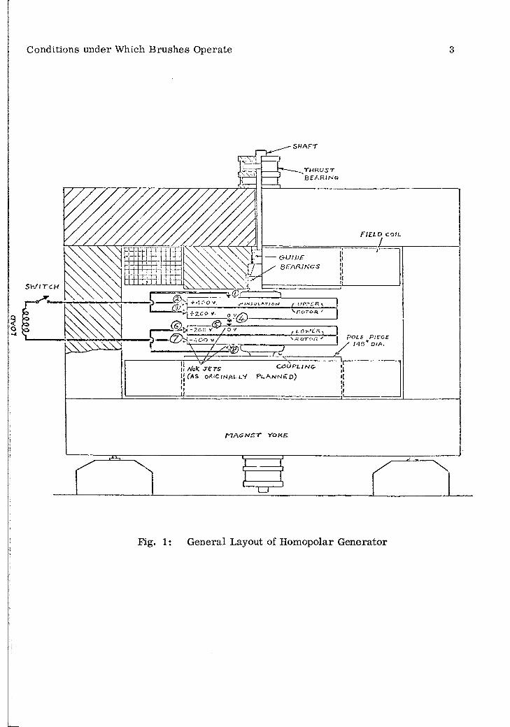
F igure 1 is a schem atic c ro ss section showing the position of the ro to rs and the method of connection through eight se ts of b rushes, which gives an open c irc u it voltage of 800 V at 900 r .p . m. The le tte ring of the ro to rs and num bering of b rush positions follows that used by M arshall.
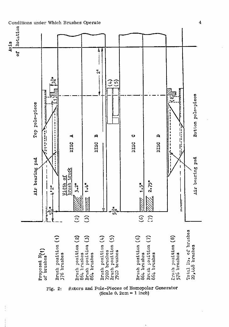
F igure 2 shows the ro to rs and pole p ieces approxim ately to scale. B rush groups (1) and (8) each operate on a copper slip ring and the sole access to the b rushgear is between ro to r and pole piece through ap ertu res in the a ir bearing pad. Groups (2), (3), (6), and (7) can work only over a lim ited band on each ro to r due to the effect of the fringing field, which gives r is e to a potential g radient in an axial d irec tion at the ro to r periphery . These bands a re indicated in F igure 2. Groups (4) and (5) a re situated in the gap between the d iscs B and C, and connect them e lec tr ica lly . D etails of the b rushgear a re d iscussed in Section 6. Magnetic fields and
OV
O 7
Conditions under Which Brushes Operate 3
SHAFT
QEARiKGS
r t/p. rn \
L O ' f - ' C AR O L E F l E O EG O '.t
C O U P L I N G ,II A 'oK. JETSij ( a s o^ ' C i n a l l V P l a n n e d )
PI A S N E T YOKE
Fig. 1: General Layout of Homopolar Generator
Conditions under Which Brushes Operate
£5 no'd 43 43 co to p O UD. rQoJ-tP* o
p o •H P •H «0 O°*g
43 4Pt/Jg ^
PQ
w0)x:«0
CvT _ t LT\— " ^ ^
a rt a po o o o
►H •H • H CO *H CO-P CO P CO -P a) p <d
•H 43 -H 43 CO to to CO
•H O •H <1>CO / I co sio to O CO o p o pPc P o . P Oi h P . H
M u 4P 4P43 S> si Si si siC/3p -H
10p - t
CO O t o O p C.M p C.NJ
U VO H vo M ON M Onpq r^- pq f —m oo W co
P P3O 0
•H •Hp ao P C5•H 0 •H Oto s i co 43O co O to
g * g43 4P 43 40c/) toP -4- P - +£1 vo H VOpq co pq uo
C3o•H
-P CO •H C) coO toQ. p
M43 ,otop vO•n v—
f-H m
COo41CO
24PO
5
r tPOEH
n<D41to
Fig. 2: Rotors and P o le-P ieces o f Homopolar G enerator(Scale 0. 2cm = 1 inch)
Conditions under Which B rushes O perate 5
voltage grad ien ts a re also indicated in Figure 2 w herever they have a bearing on the design of b rushgear.
It is proposed to operate the machine as follows. D irect c u rre n t is applied to d iscs A and D through sets of b rushes working on the periphery of the ro to rs and on slip -rin g s fitted to the stub shafts. These s lip -rin g s and brushes a re not shown. With the main field excited and all o ther b rushes lifted, the ro to rs a re brought to 900 r .p . m . , rotating in opposite d irec tions. The output busbars a re connected through a switch to a load, which will be assum ed to be the inductive load of the synchrotron winding. To obtain a pulse, all b rushes (sets 1-8) a re brought into contact (with the c o rrec t brush force) in about i second, the switch is closed and c u r ren t begins to flow. A fter f of a second the cu rren t has risen to its peak of 1 .6 x 10^ am ps and the speed has fallen to about 250 r. p. m. As the cu rren t d ecrea se s the synchrotron field begins to collapse, and energy is fed back into the ro to rs . They com e to re s t in the next J second, then rev e rse th e ir d irection of motion and a fte r a fu rth er f second, when the c u rren t instantaneously reaches zero and the switch is opened, they a re rotating at 400 r .p . m. The brushes a re then lifted.
From this b rie f descrip tion of the operating cycle of the g en era to r, the problem s of cu rren t collection can be deduced. The b rushes a re to operate a t high sliding speeds and high cu rren t densities, and they m ust have a reasonable life under these conditions. The b rushgear not only has to low er and ra ise the b ru sh es in I - J second, but m ust apply an equal load to each brush in a se t to ensure that the cu rren t distribution is uniform . B rushes m ust be held in such a way that they m aintain a stable contact while the ro to rs rev e rse , carry in g at the sam e tim e nearly the peak cu rren t. Also the fo rces due to in teraction between the local magnetic fields and cu rren ts in the brush and the leads m ust not d istu rb the contact.
In addition to these problem s there is a possib ility of therm al fa tigue occurring at the periphery of the ro to rs due to rapid heating caused by frictional fo rces and voltage drop at the sliding contact during a pulse. This problem has been trea ted thoroughly by M arshall and will be considered in Section 7.
3. 2 Com parison with Normal Conditions
The surface speeds and proposed brush cu rren t densities fo r the hom opolar generato r a re abnorm ally high. There a re th ree d istinct types of b rush position on the machine (F igures 1 and 2) and the proposed1 conditions of operation fo r these positions a re shown in Table 1. The values of Tforce p e r b rush ' and ’b rush p re s s u re ’ are the nominal applied values and neglect electrom agnetic fo rces; in c e r ta in cases these la tte r fo rces a re very high, as d iscussed in Section 7.
The lim iting values a re for p rac tica l com m ercial operation and generally do not coincide with lim its fo r fa ilu re . The periphera l speed of both com m utato rs and slip rings is lim ited by m echanical s tre s s e s and conventional fac to rs of

TA
BL
E
6
Cß35-iPQ
G05-i5-(3o
5-i ^
I '£O £
PP 3
S ^ * < 0 PP *3 ^3 Cß .?£) 5-1 3 rH O3 0 , 0 , HÜ 3 ©
01Cß
•ö <J5-i cß ' 3 ^ ^o 3 .to <;a G rH O O'
@ M
aCß35hPP
003OPh
Cß 0 0 5h ?h 3 a cß
. 330 I a £
33
33 crGp cß
33 tl)3 . 2 ?h m PQ
CßCD
O cß . 3
o ^£ m
HX£XD
33 -2S PP a cß
o a
o0
ooO
00
4-4m
oco
oLOoo
(Mo03
i—ILO
LO
o ’
. 0 3 02 £3 ^PQ 3
Cß
3O 3
4—> -HO Tj
PQ
X500acß
Cßa 3 cß O 3 ■|—13 OP
PQ M ^ o a
3<O00
o0305
OOOCOCO
o3 1
ooCO
oo3<
30aao
o
oLO05
o00l>
0
3< 3< X*0 0
8 LO3 "1
LOOj
O O 3 c— o t - 3X X a X CO X 00 Cß
CM a o ’ o ’ 3o o - X o ’ X
< 2
cotrio
ooCO
003<
co r-03 OO
« £ r f rPm
3 00m ->5 1-1Cß
033CßCß03a
aCß3332
"033
&•F— ICß30
334-4303330
aCß3332
tor-H
"g
33O34->o3
"0 r—H
O£
30>
003
3>b£>_34-4
QJ -1 0 04^4Cß ^ CD O
£
Cß03
3>bß_34-
•SH 03 3
•rH »i-H
g o
g 1
33 3 3 ai
33r—H0+433a
"3 £
.2 2 a ^hto 3
H I
3O
30344-40bß

TA
BL
E7
GU O r-H H g G
Cu - HbO ^.s I 5g S cs
&aoo
aaoo St
eel
Stee
l <0aaoo
1 S p ft o 0
1— 4 Oin
CO-GH-4>G (m
in)
(min
)
* O CO
pic
rus
Life o
a r r r O V° ä
H orH
c£> co ft MLO
a» 'H'X! G ,rHCO G •3 «1 ? H<N H<npq Ö3 (M
rH rH
a ^
1 § £09 oo
o0 0
oCM
oo^ co a* rH rH CM
% G co O TD <
r H
0) T3 O- o o o o oO 0) 2 o o o o oG O) 3
V ft so o o o LO
e. r •V
^ CO \ LO CM o o rHÜ5 -4->
CO Ü 2 ,rH rH rH
bD bJD
Go
GS
GO
Ö•rH
•rHo
a a & a a
H•rH
H H•rH
h H H
COg bJD bJDo G G G „— ^
G•rH
H->ctf+->
• H
'So
4->c j
•rH
'SG
. 2x i
GGa
GCO
GGGCO
4-H
G "Öa a G
CO O4-> a §
<D Gt j o
«4-1O
o>
&
0
u
u
0> G G GrH -l-H
■ f t £
8 §<o
f tGH
a § a s
c j
& O
3 O5 “® o “
H Q a £ H CO w ü a ^

Com parison with Normal Conditions 8
safety d ifferent to those in the case of the hom opolar generato r. The cu rre n t densitie s quoted a re lim ited by consideration of b rush w ear, com m utation quality and tem p e ra tu re r is e . A typical requirem ent on conventional m achines is fo r at leas t six months brush life on continuous full load, o r in the case of c a r s ta r te r m otors, for 50, 000 s ta r ts without replacing brushes. Obviously, if such b rush life requirem ents a re to be waived, and provided that excessive tem p era tu res a re not encountered, then the b rush c u rre n t density may be increased fa r above what a re norm ally regarded as lim iting values.
The very high brush cu rren t densities on the hom opolar generato r n ecessita te the use of high copper content b rushes. B rushes with a high s ilv e r content may be m arginally be tter since they have a very slightly higher e lec trica l conductivity, but the cost of s ilv e r b rushes is so much g re a te r that it is not recom m ended that they be seriously considered. On the basis of experience on conventional m achines it could be fo recast, before examining the experim ental re su lts given in the next two sections, that the b rushes m ost likely to give optimum perform ance would be of the following two types:
(a) Automobile s ta r te r b rushes
This application is the m ost well known of all 'pu lse ' applications fo r b rushes involving higher than norm al cu rren t density. High copper content brushes a re always used. A typical com position is:
copper - 85%lead - 10%graphite - 5%
(b) Heavy duty slip ring b rushes
These commonly operate at continuous b rush cu rre n t densities up to 150 A /sq . in. There a re two main types, firs tly , co p p er/lead /g rap h ite grades s im ila r to those used for automobile s ta r te r b rushes and, secondly, c o p p e r /le a d /tin /g ra - phite grades. A typical com position for the la tte r is:
copper - 80%lead - 5%tin - 5%graphite - 10%
They a re usually re fe rre d to as 'bronze graphite ' m ateria l. Howev er, the conditions on the hom opolar generato r a re so d ifferent from conventional applications that experience alone was not sufficient to indicate which of many p o ssib le high copper content grades would be the optimum. Experim ental work was initiated a t B atte rsea in o rd e r to give an indication of the optimum grade when choosing between high copper content grades with m arginal differences in com position.

4. Experim ental P rogram m e C arried Out by M organite at London
9
P r io r to our departu re at sho rt notice fo r A ustralia , an urgent program m e of experim ental work was initiated at B atte rsea in o rd e r to se lec t the optimum brush grades for running under conditions of high speed, cu rren t density and load. The appara tu s used and te s t conditions w ere:
T ests on Copper s lip -rin g s
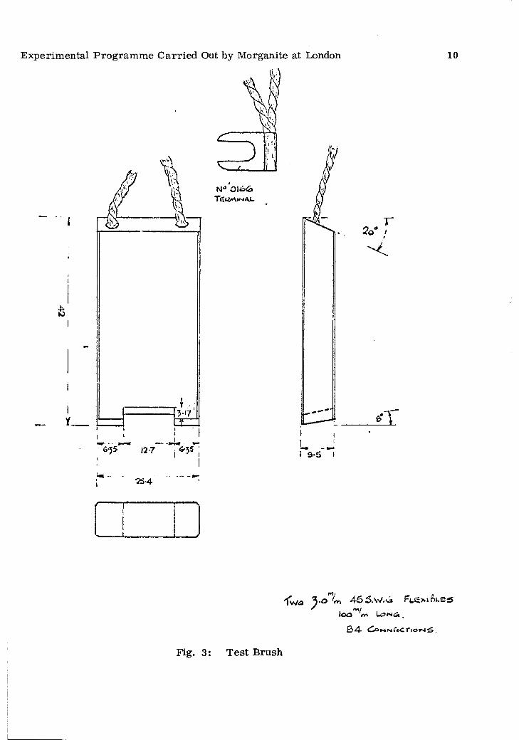
A pparatus: Copper s lip -rin g , 9 in. d iam eter, 1 -1 /8 in. wide128 axial slo ts each 0. 8 mm wide x 1.6 mm deep D irectly driven by d. c. m otor4 b rush holders, 1 in. x 3 /8 in. section, 8 tra iling 2 positive and 2 negative b rushes connected in pa ra lle l with a lternate positive and negative b rushes around the s lip -rin g periphery .D etails of the b rush design a re shown in Figure 3: half of the b rush face was cut away in o rd e r to double the cu rren t density com pared to that norm ally obtainable.
T est conditions:
(1) Continuous running: p eriphera l speed 8000 ft/m inbrush p re s su re 8 psicu rren t density 240 A /sq . in.cu rre n t/b ru sh 45A
(2) Pulse cu rren t test: cu rren t pulse duration 5 secondsno cu rre n t for 30 secondsrepeated for one hour pulse c u rren t density 1000 A /sq . insubsequently increased to 2000 A /sq . in
T est procedure:
P r io r to each te s t the rings w ere turned with a diamond tipped tool and th e ir slo ts lightly Tveed?. The rings w ere then polished with well worn 100 g rit C a r- bo rundun paper. Each brush w as, in turn , radiused with 100 g rit Carborundum paper and finished with 320 Durex paper. A fter bedding, the machine, b rushes, and brush boxes w ere wiped clean to rem ove copper and carbon dust.
A fter p reparation the b rushes w ere run at the te s t condition (1) for a bedding period of approxim ately 18 hours, during which tim e running perform ance was c losely observed. The brush lengths w ere m easured at the end of the bedding period and the te s t p roper commenced. Hourly readings of positive, negative and total contac t voltage and coefficient of fric tion w ere made. Following a te s t period of approxim ately 48 hours running, a contact drop - cu rre n t density curve was taken up to
Experim ental P rogram m e C arried Out by M organite at London
3 5 4
10
5 .o"™ 455 .W .Ü » F L e* » f o «' <v»/loo «r» Lu>fs«ä .
£> n IV» riorNi 5 ,
Fig. 3: Test Brush

Experim ental P rogram m e C arried Out by M organite at London 11
approxim ately 1000 am p s/sq . in. Any brush grades which did not spark during the m easurem ent of the contact drop - cu rren t density curve w ere then subjected to c u rren t pulses for not le ss than one hour a t 1000 am ps/sq . in. and fo r not le ss than 35 m inutes at 2000 am ps/sq . in. , during which tim e a pen record ing was made of the total contact voltage. The pulsing was so arranged to give a 5 second cu rren t pulse followed by 30 seconds at no c u rren t (condition 2). At the end of the pulsing te s ts , the machine was shut down and final b rush lengths m easured.
G rades tested:
T ests w ere c a rr ie d out on six standard M organite grades - CM+O, CM-O, CM, CM1S, CM2 and SM7938. The CM grades listed all have a high proportion of copper: 80-90% by weight. The SM7938 contains a high percentage of s ilv e r. These g rades w ere chosen for te s t on account of th e ir high e lec trica l conductivity and low contact drop as required for the very high pulse cu rren t densities on the hom opolar generato r. T}qDical physical p ro p ertie s fo r these g rades, and fric tion and contact drop te s t re su lts under standard conditions, a re given in Table 3.
T ests w ere also c a rrie d out on a d enser than norm al version of CM1S - denoted CMIS(DE): also on b rushes having a 1. 5mm dia. hole vertica lly in the centre of each section of the two running faces p e r brush (Figure 3). These d rilled b rushes a re denoted (DR). The aim of the holes was to alleviate the possib le build up of a ir p re s su re at the contact face under these high speed conditions. The re su lts a re given in Table 4.
Four specially form ulated v arian ts of CM1S and CMO w ere p repared and tested , but since the re su lts w ere not b e tte r than for the standard g rades these w ill not be detailed. The code num bers fo r these grades, some of which w ere also tested at C anberra, w ere VH496 E1251, VH496 E1253, VH496 E1255 and VH496 E1257.
R esults: The re su lts a re sum m arised in Table 4.
It will be observed that the only grade which perform ed sa tisfac to rily up to the 2000 A /sq . in. pulse condition was CM1S. The CMIS(DE) gave a significantly low er ra te of b rush w ear but was associated with occasional 'sp itting ' at 2000 A /sq . in It m ust be pointed out that only one te s t could be done on each grade in the short tim e available. On the b asis of experience of re la tively sho rt te rm te s ts of this nature any difference in average values of contact drop o r friction le ss than 10% between grades is not significant, and any different in w ear le s s than 25% is not significant.
The inability of CM+O and CM-O to run sa tisfac to rily under continuous loading is in agreem ent with general experience. These grades a re designed fo r autom obile s ta r te r m otors. However, since this pulse type of duty is s im ila r to that on the hom opolar g enera to r th e ir inability to run on continuous load is not p a rticu la rly re levan t.

Experim ental P ro g ram m e C arried Out by M organite at London 12
The re su lts do not indicate that the d rilling had any significant effect. In o rd e r to confirm that the perform ance of CM1S was satisfac to ry on stee l s lip -rin g s the following te s t was c a rr ie d out at the continuous loading of 240 A /sq . in. This grade is not norm ally run on stee l s lip -rin g s .
T ests on high speed grooved steel s lip -rin g
This s lip -rin g is a rep lica of a turbo a lte rn a to r type of s lip -rin g .
Ring details:
T est conditions:
R esults:
Steel S iip-ring m ateria l to B .E . A. M. A. Spec. (Grade 2) Ring dia. 26 in. (66 cm)Ring width 2§ in. (7 cm)Turned with one helical groove 1/8 in. wide x 3/16 in. deep P itch = \ in.
P e rip h e ra l speed Continuous cu rren t density Spring p re ssu re No. of b rushes B rush section B rush holders
- 15, 000 ft/m in- 240 A /sq . in.- 8 lb /sq . in.- 12- As for F igure 3- As fo r te s ts on slotted
copper rings.
Coefficient of Average C. D. (V) AverageGrade friction brush life
Ave. Range +ve -ve (h rs/in )
CM1S . 09 .0 7 /.1 1 0.36 0.37 700
O ccasional slight pin point sparking was observed on som e brushes.
B rush surface descrip tions: T rack 1 (positive)Smooth, very highly polished surface of a light chocolate colour, with slight sparking m arks.
T rack 2 (negative)As for T rack 1 but some su rfaces had a few sm all dull a re a s .
Ring surface descrip tions: T rack 1. Smooth, very highly polished surface of alight copper ta rn ish . One d a rk e r band observed.
T rack 2. Smooth, very highly polished su rface with only very slight tra c e of copper.

Experim ental P rogram m e C arried Out by M organite at London 13
Other te s ts
We ju st had tim e to c a rry out two b rie f experim ents to a sse ss the behaviour of b rushes a t even higher cu rre n ts . In the f i r s t a static contact between a brush and a mild steel su rface was pulsed at peak cu rren ts of 700 am ps to obtain an approxim ate value of contact drop. The b rush section was 0. 2 in. x 0. 2 in. and the load approxim ately 60 p si. Pulse duration was 2 m illiseconds. Contact drop was m easured in th is way fo r th ree g rades, CMO, CM1S, and CM2, and the values obtained w ere 0. 45v, 0. 54v and 0. 51v, respectively .
Dynamic te s ts w ere c a rr ie d out at 2500 ft/m in . using two b rushes o p era ting on a flat m ild steel s lip -rin g . P rov ision was made fo r passing cu rren t pulses up to 2000.am ps through the b rushes, which w ere 0. 2 in. x 0. 2 in. section. The grades used w ere CMO, and CM1S, and the applied load 6 psi. At th is load CMO was found to spark vigorously during a pulse of 70 amps fo r one second. CM1S generally gave le s s sparking, and at 10 psi would operate at 200 amps with only slight sparking.
These experim ents showed that the stiffness of the leads, which it was necessa ry to fit to the b rushes in o rd e r to c a r ry 2000 am ps, d isturbed the stability of contact. This may well be a problem when using b rushes guided by a holder even with m ore favourable brush dim ensions.
Conclusions
The ability of CM1S to withstand 2000 A /sq .in . pu lses at 8000 ft/m in and 8 lb /sq . in. was regarded as prom ising and w orthy of fu rth er testing at C anberra under conditions n e a re r to those on the hom opolar generato r. It was also considered that CM+O and CM-O should be tested at C anberra, in spite of the poor re su lts at B a tte rs e a —there not being sufficient tim e to te s t these grades thoroughly under pulse conditions.
5. Experim ental P rogram m e at C anberra
Before an experim ental p rogram m e was in itiated to a s s is t in the choice of a brush m ate ria l for the homopolar generato r, Mr. M arshall outlined the resu lts of h is experim ents on two te s t rig s , both of which a re described in h is repo rt. One has a 2 in. d iam eter ro to r which can be operated up to 60, 000 r .p . m. This is fitted with 8 b rushes and has been used to investigate therm al fatigue of ro to rs and methods of w a ter cooling. The o ther has an 18j in. d iam eter mild stee l ro to r operating at 6, 000 r . p. m . , giving a surface speed of 32, 000 ft/m in , and is fitted with two brush holders which a re basically s im ila r to those proposed fo r positions 2, 3, 6 and 7 of the homo- p o la r generato r. Conditions on the 18j in. d iam eter rig a re m ore nearly com parable w ith those of the generator, although it w ill not sim ulate the therm al loading required , and it was decided to use this ra th e r than the 2 in. rig for the evaluation of experim enta l brush grades.

14
TABLE 3
Properties of Morganite Brush Materials
Not to be published without perm ission from Morganite Carbon L td ., London. These figures are averages from a large number of test results.
CMO CM CM1S CM2 SM7938
Compressive strength (lb/sq. in .) 18,800 12,500 * 19,500 8, 580
Shear strength (lb/sq. in .) 3, 790 3, 180 6, 240 2, 710
Modulus of Elasticity in Compression (lb /sq .in .) 0. 91xl06 61.0x10 0. 82x106 0 .04xl06
Izod impact (ft-lb) 0. 29 0. 29 0.62 0.20
Soleroscope hardness 4-7 5-7 7-11 13-17 10-13
Bulk density (gm /cc) 6. 5 6. 1 5. 5 4 .7 7 .4
Air permeability (cm /sec)
Thermal expansion per °C
3xlO”S
17x10
3xl0~8
17x10"
lxlO ”8
16x10"
3 . 2xl0"8 -615x10
Thermal conductivity fcal/cm 'V sec/(°C /cm )) 0.30 0.30 0.18 0. 33
Specific heat (cal/gm°C 0. 089 0. 092 0. 096 0. 11
Rockwell hardness
Specific resistance
47
2.5x10 ^
35ry
3. 5x10
37
15xl0”6 5 .5 x 1 0 ° 1.3x10"
9 in. dia. slotted copperring. 2 lb /sq . in. (Brushes 1 in. x 3 /8 in. section)
Friction coefficient (55 A /sq. in .)
3500 ft/m in 17500 ft/m in
5000 ft/m in 2500 ft/m in
0. 19 0. 23
0.10 0.18
0. 09 0. 16
0.09
0. 08 0. 13
Contact drop/brush (3500 ft/min)
55 A /sq . in. 27.5 A /sq . in.
0. 180. 10
0.13 0.09
0. 16 0.11
(5000 ft/m in)
0.17 0.100.15

Exp
erim
enta
l Res
ults
on
9 in
. D
ia.
Cop
per
Sli
p-R
ings
15
Rem
arks
ä £cd c g c0 r
£ ia
ö :£ ^ o
^ 0 +-> t 3 rC
rd -CG ^XI >•H> <•oPQ l p
i W
A.
LU
11
X0
. U
UC
op.
i. e
. co
nt.
spar
k &
occ.
sp
itti
ngN
ot p
ulse
d.
Spa
rked
@
700
A/s
q. in
.N
o sp
ark,
ob
serv
ed
@
2000
A/s
q. i
n.
puls
e (3
5 m
in d
urat
ion)
Spit.
&
spar
k.
@ 5
000
A/s
q. in
.O
cc.
spit
@ 2
000
A/s
q. i
n.
puls
ing
Hea
vy b
rush
wea
r w
ith
cons
id.
spit
'g.
@ 2
000
A/s
q. i
n.
puls
ing
ÜPQ . 5
> i «.00LO . CO
LOCOLO 58
Q \ £ o ’ o ’ o ’ •o ^S r—1 ,<D ° Or bX3 ° CO O CO CO
cdjD
Ö o cd S' P5 @
COo ’
COo ’
COo ’
CO
<DCG
r—HPQ .£ LO 05
Ph \ 00 r-1 CO o t-> CGCO mQ \ m
rHo ’
©1 ©
CM rH©
ü < 3 1 1 i CO1 ‘ 1
<u o H, CM o o CM 00bJO o £ o rH tH 1—1 rH o03 rH o ’ o ’ * o ’
Ph @)
rnLO O o o o o o o
X* •2 -2 O LO
3 <2 EG i 00 rt* i ^ co CM O o o h \ CO 05
co tri rH rH rH tH Ä o gCO rH
+ 1 + i + 1 + i < ^ s i + 1
£ CO CO CO CO LO 00\& 7JT
Gcd<D
05O
COo
COrH COo
LOo
COo
CMo
rHO
or—HO a O o ’ o* o ’ o ’ o ’ o ’ o ’
o S cu rH CM LO COo > 05 LO 05 CO LO CO CM• • rH
Ö ••rHi
© o © © © © © ©' CG o
U* \ cd\ <
+-> £ Q rH rH CO rH CM
5 ° oO
>+
05o
CMO
CMCM
COo
LOo
CMO
CMo
rHo
00 CM o ’ o ’ o ’ o ’ o ’ o ’ o ’ o ’T3cd Q) 00 00 \ H 00 LO 00 oo oO bn o rH rH tH rH rH rH CM
CGf icd \ \ \ \ \ \
O3 O
PP o tH rH . rH 1—1 rH rH rH
Ö
Ö fci> tH LO o LO CO LO 00o
U CrH rH tH rH tH rH
PPw W Q
<D P p Q ~ 00 007 3 O O GO c/T Ph m g CO
05CO05
GÜ
4 "§
iS §
rH§
CMS
tH
srHs
1—1 H.S
t>§
t-
o u u U Ü u u O in m
r— I »—H
'uQ
uCGSOQ
W « Q Q
ing:
1
x1
.5 m
m d
ia.
hole
ver
tica
lly
in t
he c
entr
e of
eac
h se
ctio
n of
run
ning
fac
e.
Experim ental P rogram m e at C anberra lö
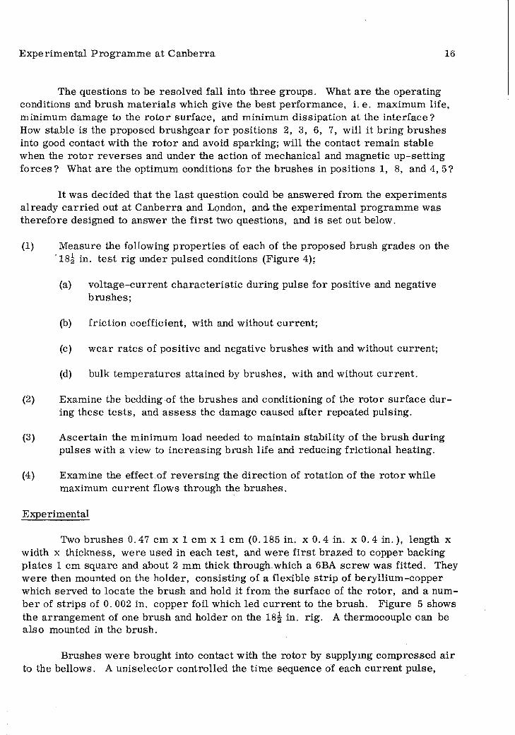
The questions to be reso lved fall into th ree groups. What a re the operating conditions and b rush m a te ria ls which give the best perform ance, i. e. maximum life, m inimum damage to the ro to r su rface, and minimum dissipation at the in te rface? How stable is the proposed b ru sh g ear for positions 2, 3, 6, 7, will it b ring brushes into good contact with the ro to r and avoid sparking; will the contact rem ain stable when the ro to r re v e rse s and under the action of m echanical and magnetic up-setting fo rce s? What a re the optimum conditions for the b rushes in positions 1, 8, and 4, 5?
It was decided that the la s t question could be answ ered from the experim ents a lready ca rried out at C anberra and London, and the experim ental program m e was therefo re designed to answ er the f i r s t two questions, and is se t out below.
(1) M easure the following p ro p e rtie s of each of the proposed brush grades on the 18^ in. te s t rig under pulsed conditions (Figure 4);
(a) vo ltage-cu rren t c h a rac te ris tic during pulse fo r positive and negative brushes;
(b) fric tion coefficient, with and without cu rren t;
(c) w ear ra te s of positive and negative b rushes with and without cu rren t;
(d) bulk tem p era tu res attained by brushes, with and without cu rren t.
(2) Examine the bedding of the brushes and conditioning of the ro to r su rface d u ring these te s ts , and a sse ss the damage caused a fte r repeated pulsing.
(3) A scertain the minimum load needed to m aintain stability of the brush during pulses with a view to increasing brush life and reducing frictional heating.
(4) Examine the effect of rev e rs in g the d irection of ro tation of the ro to r while maximum cu rren t flows through the b rushes.
Experim ental
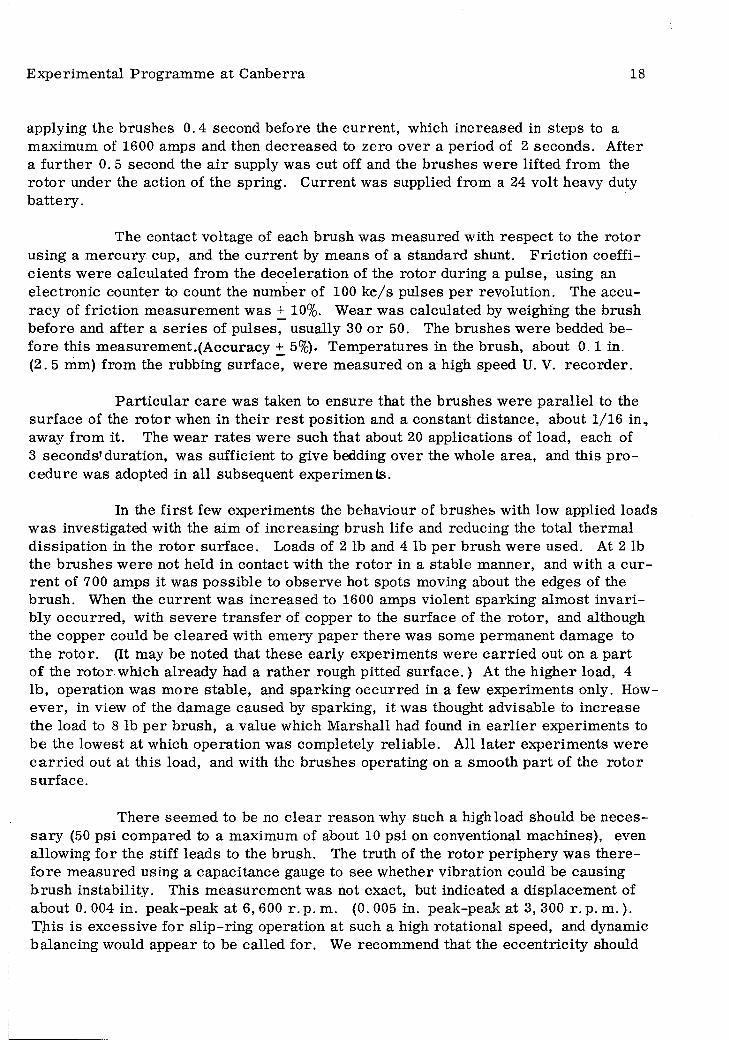
Two brushes 0. 47 cm x 1 cm x 1 cm (0.185 in. x 0. 4 in. x 0. 4 in . ), length x width x thickness, w ere used in each test, and w ere f i r s t brazed to copper backing p la tes 1 cm square and about 2 mm thick through which a 6BA screw was fitted. They w ere then mounted on the holder, consisting of a flexible s tr ip of bery llium -copper which served to locate the brush and hold it from the surface of the ro to r, and a num b e r of s trip s of 0. 002 in. copper foil which led cu rren t to the brush. Figure 5 shows the arrangem ent of one b rush and holder on the 18j in. rig . A therm ocouple can be a lso mounted in the brush.
B rushes w ere brought into contact with the ro to r by supplying com pressed a ir to the bellows. A un iselec to r controlled the tim e sequence of each cu rren t pulse,
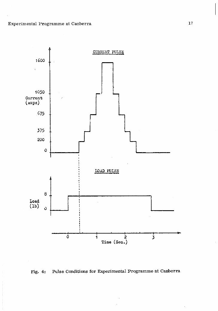
E x p e r im e n ta l P ro g ra m m e a t C a n b e rra 17
CURRENT PULSE
1600 ..
1050Current(am ps)
LOAD PULSE
Time (Seo.)
F ig . 4 : P u ls e C o n d itio n s f o r E x p e r im e n ta l P ro g ra m m e a t C a n b e rra
E xperim ental P rogram m e at C anberra 18
applying the b rushes 0 .4 second before the cu rren t, which increased in steps to a m axim um of 1600 amps and then decreased to zero over a period of 2 seconds. A fter a fu r th e r 0. 5 second the a ir supply was cut off and the brushes w ere lifted from the ro to r under the action of the spring. C urren t was supplied from a 24 volt heavy duty b a tte ry .
The contact voltage of each brush was m easured with re sp ec t to the ro to r using a m ercu ry cup, and the cu rren t by m eans of a standard shunt. F ric tion coeffic ien ts w ere calculated from the deceleration of the ro to r during a pulse, using an e lec tron ic counter to count the num ber of 100 k c /s pulses p e r revolution. The accuracy of fric tion m easurem ent was + 10%. W ear was calculated by weighing the brush before and a fte r a s e r ie s of pulses, usually 30 o r 50. The brushes w ere bedded befo re th is m easurem ent.(A ccuracy + 5%). T em peratu res in the brush, about 0 .1 in.(2 .5 mm) from the rubbing surface, w ere m easured on a high speed U. V. reco rd er.
P a rtic u la r c a re was taken to ensure that the b rushes w ere p a ra lle l to the su rface of the ro to r when in th e ir r e s t position and a constant distance, about 1/16 in , away from it. The w ear ra te s w ere such that about 20 applications of load, each of 3 seconds'duration , was sufficient to give bedding over the whole a rea , and this p ro cedure was adopted in all subsequent experim ents.
In the f i r s t few experim ents the behaviour of b rushes with low applied loads w as investigated with the aim of increasing brush life and reducing the total therm al d issipation in the ro to r su rface . Loads of 2 lb and 4 lb p e r brush w ere used. At 2 lb the b rushes w ere not held in contact with the ro to r in a stable m anner, and with a c u rren t of 700 am ps it was possib le to observe hot spots moving about the edges of the b ru sh . When the cu rren t was increased to 1600 amps violent sparking alm ost invari- bly occurred , with severe tra n s fe r of copper to the surface of the ro to r, and although the copper could be c lea red with em ery paper there was some perm anent damage to the ro to r. (It may be noted that these early experim ents w ere c a rr ie d out on a p a rt of the ro to r which already had a ra th e r rough pitted s u rfa c e .) At the h igher load, 4 lb , operation was m ore stab le, and sparking occurred in a few experim ents only. Howe v e r , in view of the dam age caused by sparking, it was thought advisable to increase the load to 8 lb p e r brush, a value which M arshall had found in e a r lie r experim ents to be the low est at which operation was com pletely re liab le . All la te r experim ents w ere c a r r ie d out at this load, and with the b rushes operating on a smooth p a rt of the ro to r su rface .
There seem ed to be no c lea r reason why such a high load should be n ecess a ry (50 psi com pared to a maximum of about 10 psi on conventional m achines), even allowing fo r the stiff leads to the brush. The tru th of the ro to r periphery was th e re fo re m easured using a capacitance gauge to see w hether vibration could be causing b ru sh instability . This m easurem ent was not exact, but indicated a displacem ent of about 0. 004 in. peak-peak at 6, 600 r. p. m. (0. 005 in. peak-peak at 3, 300 r. p. m . ). T his is excessive fo r s lip -rin g operation at such a high rotational speed, and dynamic balancing would appear to be called for. We recom m end that the eccen tric ity should
Experim ental P rogram m e at C anberra 19
CLAMP
SCALE (INCHES)
— <
TERMINALCLAMP
Fig. 5: Brushgear on 18.1/2 inch Diameter Rig
Rs p h y s .s \' / P Y
Experim ental P rogram m e at C anberra 20
not be m ore than 0. 001 in. Following dynamic balancing the effect of working at r e duced loads could usefully be investigated. A reduction in load from 8 lb to 4 lb, which should s till be high enough in relation to magnetic and frictional force to ensu re stability , would approxim ately double brush life and halve the frictional heating with only a slight increase in contact drop.
The main se r ie s of experim ents was then c a rrie d out using the following standard and experim ental brush grades:
CM1S VH496 E1257 CMls(DE)(CM903) (CM902)
CM-O CM+O CM904
A fter bedding, the b rushes w ere applied to the ro to r for 3 seconds without passing cu rren t, and with 30 seconds between each application. A fter 30 o r 50 pulses, during each of which the friction coefficient was m easured , both b rushes w ere weighed and th e ir w ear ra te s calculated. The brushes w ere subjected to a fu rth e r 30 o r 50 pulses with cu rren t flowing. F riction coefficients and w ear ra te s w ere again m easured. A sum m ary of the re su lts obtained is given in Table 5.
The effect of rev ersin g the d irection of rotation of the ro to r while the b rushes c a rry maximum cu rren t (1600 amps) was investigated, to see w hether the b rushes m aintained a stable contact, o r w hether overheating o r burning took place. A fter modifying the brush holders to locate the b rush co rrec tly in both d irections, the ro to r was oscillated slowly to and fro by hand with the cu rren t on. There was no evidence of sparking, and only a slight in crease in contact drop at the instant of re v e rsa l. No sign of burning o r o ther damage was visib le on the ro to r.
Conclusions
1. On the basis of the experim ental re su lts obtained in London, and thosedescribed above, we se lec t CM1S as being su p erio r in perform ance to the other g rades tested , and we therefo re recom m end th is grade for tr ia l on the homopolar generato r.
R eferring to Table 5 it will be seen that the w ear ra te s p e r pulse for CM903, CM+O and CM904, w ere significantly g re a te r than for the o ther grades CM1S, CMIS(DE), and CM-O. F urther, CMIS(DE) suffered from high friction without having any com pensating advantage in w ear ra te o r contact drop re la tive to CM1S and CM-O.
CM1S has a higher friction coefficient than CM-O, but slightly lower w ear ra te However, the slope res is tan ce (i.e . the slope of the vo ltage-cu rren t ch arac te ris tic ) at the working cu rren t is g re a te r with CM1S than CM-O, and offers an advantage in helping to suppress uneven cu rren t d istribution due to the voltage
Experim ental P rog ram m e at C anberra 21
gradient on the ro to r. CM-O did not behave sa tisfac to rily in London, and M arshall has found, in some of his e a r lie r experim ents, that the friction and contact drop of CM-O did not always rem ain steady, and that sparking som etim es occurred . F o r these reasons CM1S appears p referab le .
2. Under the conditions used in these experim ents, which w ere s im ila r in many re sp ec ts to those proposed for the ro to r rim b rushes of the hom opolar g en era to r, all the b rush grades tested w ere found to perfo rm sa tisfac to rily fo r a to tal of sev era l hundred pu lses. There was no sparking; the ro to r surface becam e polished ra th e r than damaged; friction coefficients w ere constant fo r each grade and independent of the passage of cu rren t.
3. W ear ra te s w ere generally consisten t fo r both b rushes used in each ex p erim ent and, except fo r CM903 and CM904, w ere not significantly a lte red by the passage of cu rren t. W here the d istribution of cu rren t in a brush is not uniform , i. e. when it o p era tes in the p resence of a potential gradient, the fact that w ear is independent of c u rre n t is of considerable im portance. Many of the outer rim b rushes for exam ple will operate under these conditions.
The m ean w ear ra te of CM1S was 0. 00019 in. p e r pulse, giving a th e o re tical brush life of 1000 pulses (0. 2 in . ) a t positions 2, 3, 6, and 7.
4. With a load of 8 lb p e r brush there was no sign of contact instability at any tim e, and it was also possib le to re v e rse the d irection of rotation of the te st ro to r without causing burning o r sparking. We therefo re consider that the form of b rush ho lder proposed for b rush positions 2, 3, 6, and 7, which is s im ila r to that used in these experim ents, is likely to be sa tisfac to ry . However, we recom m end that the final form of b rush holder be tested fo r stab ility with the spring in a vertica l position as it would be on the hom opolar generato r.
5. The re su lts obtained by using a reduced load of 4 lb p e r brush w ere encouraging, and we recom m end that fu rth er te s ts be ca rried out at th is load, p re fe ra bly on the hom opolar generato r using an external power supply.
6. B rush Design
T here a re th ree d istinc t b rush design problem s on the hom opolar g en era to r, namely:
(1) R otor rim b rushes (positions 2, 3, 6, and 7).(2) Top and bottom inner b rushes (positions 1 and 8).(3) Mid inner b rushes (positions 4 and 5).
These problem s will be considered separately . This section mainly deals with m echanical aspects of the b rush design; m agnetic, e lec trica l and therm al effects a re considered in detail in Section 7.

22
TABLE 5
R esu lts of Experiments at C anberra on 18^ in. Dia. T est Rig (All resu lts a t 6, 600 r. p. m . , except where indicated)
Grade. CM1S VH496 E1257 (CM903)
CM1S(DE)(CM902) CM-O
no curren t 0.221 0. 196 0. 278 0. 17y curren t 0. 205 0. 198 0. 271 0.20
Polarity + + + +Brush no cu rren t 106.3 75.3temp. ( C) cu rren t 139.5 128.0 .W ear per no cu rren t 0.174 0.185 0.309 0.279 0.244 0.242 0.285 0.073pulse (xlO in) cu rren t 0.212 0.175 0.557 0.514 0.197 0.251 0.248 0.175Contact volt pulse No. 1 1 1 1 1 1 1 1drop at 1650 A volts 0.725 0.85 0.75 0.8 0.725 0.725 0.7 0.8approx. pulse No. 30 30 30 30 30 30 30 30
volts 0.70 0.725 0.6 0.70 0.65 0.725 0.63 0.68Slope res is tance ( o h m s x l 0 - 4 ) 2.5 1. 8 3 .8 1.0
Grade: CM+O CM904 CM1Srepeat
CM1S (3300 rpm)
no cu rren t 0. 198 0. 19 0. 25 0 . 249y curren t 0. 20 0. 17 0. 22 0 . 238
Polarity + + + + -
Brush no cu rren t 61. 0 55. 5temp. (°C) cu rren t 124 123W ear per no cu rren t 1.3 1.2 0.47 0.40 0.138 0.189 0. 064 0. 060pulse (xl0~3in) curren t 1.1 0.76 0.76 0.82 0.22 0.138 0. 085 0. 076Contact volt pulse No. 1 1 1 1 1 1 1 1drop at 1650 A volts 0.55 0.75 0.8 0.75 0.75 0.85 0. 75 0. 70approx. pulse No. 7 -7 30 30 30 30 30 30
volts 0.50 0.775 0.75 0.70 0.70 0.75 0. 55 0. 6Slope res is tance (ohmsxlO -4) 2.6 1 . 0 2. 5 3 0

B rush Design 23
6. 1 R otor Rim B rushes (positions 2, 3, 6 and 7)
In general, we a re in agreem ent with the specification and com m ents given on pages 12-17 of M arsha ll's repo rt. However, we draw attention to the following:
Brush Losses - With the proposed design the brush cu rren t density of 11, 600 A /sq . in. is a lm ost twice that for the b rushes in the o ther positions (Table 1).In addition, the proposed nominal force of 8 lb p e r b rush re su lts in a p re ssu re of 51 lb /sq . in. which is th ree tim es that fo r any o ther position: due to the highdr surface speed the necessity for a higher brush p re ssu re in o rd e r to m aintain b rush contact stab ility would be expected, but we question w hether the proposed p re s su re is not excess iv e; M arshall calcu lates the power loss p e r square cm. of ro to r su rface at full speed and peak cu rren t cu rre n t for a 1 cm wide band of brushes to be:
(a) due to friction: 0. 94 kW(b) due to contact volt drop: 0. 80 kW
Since friction heating is so im portant for the ro to r rim brushes, and on the basis of re su lts d iscussed in Section 5, we recom m end that, firs tly , the possib ility of reducing the brush force be reconsidered; this would have the effect of reducing the ro to r tem p era tu re and increasing brush life. Secondly, we recom m end that increasing the b ru sh a re a by increasing the brush thickness be considered; this would necessita te staggering the b rushes axially in each brush unit. The effect would be to reduce the fric tion and contact drop lo sse s p e r unit a re a of the brush, with consequently reduced brush tem p era tu res and increased brush life. The minimum to lerab le brush p re ssu re m ust be a sse ssed by experim ent, the minimum being that at which ro to r su rface im perfections and electrom agnetic fo rces on the brush system lead to sparking due to instantaneous lo ss of contact between brush and ro to r.
B razing - The brazing of 864 brushes to b rush mounting s trip s , fo r each of four positions, is a form idable operation. It is recom m ended that m eticulous a ttention be given to the inspection procedure for assess in g the quality of these jo in ts. It is suggested that the e lec trica l re s is tan ce of the joint may be a useful non-destructive te s t of quality, but in addition a destructive te s t of m echanical strength should be undertaken on at le a s t 5% of the b razed jo in ts.
Fatigue - A te s t should be initiated to determ ine any possib le fatigue effec ts on the b rush mounting s tr ip s associated with the continual application of the b ru sh es . The m echanical and fatigue strength of all components of the b rushgear should be beyond doubt since the development of loose p ieces during operation of the hom opoiar generato r could have serious consequences.
S eries R esis to rs - We endorse the use of these fo r both the reasons given"*": i. e. to im prove the sharing of load cu rren t between brushes and to m inim ise the effect of the voltage difference on the brush track .
B rush Design 24
B rush stab ility - C are should be taken to ensure that the proposed brush length of approxim ately 0 .2 in. is not exceeded by an excessive amount since this could lead to brush chattering associated with friction force - in spite of the 'an ti- topple' s tr ip , which may not have sufficient damping to obviate th is danger.
F itting of B rushes - C are should be taken that they a re fitted ’sq u are ’ r e lative to the ro to r and that the nut on the back of each brush is locked in position.
B rush Length - With b rushes of equal initial length the gaps between the ro to r and individual b rushes in a unit of twelve b rushes would not be equal, with the b rushes ra ised - see F igure 12 of M arshall’s rep o rt. This n ecessita te s having b rushes in itially longer than nominal (0. 2 in . ) and then bedding them to the c o rre c t cu rv a tu re on a suitable machine so that all the b rushes in each unit initially contact the ro to r sa tisfac to rily . The alternative, ap art from appropriate redesign of the b ru sh g ear, is to have b rushes of d ifferent initial length for each position in a unit. This is possib le , but would greatly com plicate m anufacture and m aintenance.
Staggering of B rush Positions - The axial stagger of the brushes should be such that each p a rt of the ro to r surface in contact with b rushes sweeps under the sam e num ber of b rushes. If this ru le is not observed then unequal w ear and film fo rm ation w ill occu r at d ifferent axial positions on the brush track .
B rush P u sh er M echanism - We a re generally in agreem ent with the p ro posed design (F igure 12): however, we have not considered all the details involved. The m ate ria l fo r the b rush pusher cap is not specified in M arsh a ll's repo rt - it m ust be both an e lec trica l insu lato r and able to withstand the high tem p era tu res in the v icinity of the b ru sh es.
6. 2 Top and Bottom Inner B rushes (Positions 1 and 8)
We have the following com m ents on the specifications as given on pages 33-35 and in F igure 15 of M arsha ll's re p o r t:1
S lip -rings - The 48 in. d iam eter copper s lip -rin g s should preferab ly be forged, ro lled , o r c a s t and then ro lled , in a continuous ring. We understand from d iscussions a t C anberra that it is proposed to produce rings with a soldered joint. A perm anently jointed slip -rin g of th is nature for carry ing heavy cu rre n t is outside our experience o ther than fo r tem porary purposes o r for carry ing light cu rren t signals.It should be noted that, f irs tly , any jointing m ateria l (hard o r soft solder) coming to the surface of the s lip -rin g may cause a local contact irreg u la rity which may become cum ulatively w orse and thus lead to fa ilu re . Secondly, if a m echanical, ra th e r than a m etal joint, is used then we would anticipate difficulty in avoiding a step at the joint. We recom m end that any step should be le ss than one ten-thousandth of an inch at full speed, which is the generally accepted to lerance between adjacent com m utator b a rs fo r com m utators of roughly this d iam eter (48 in . ). If a jointed ring has to be used
B rush Design 25
because of d ifficulties in A ustra lia with the o ther suggested m anufacturing techniques, then we suggest that, if feasib le , it be copper welded. The hardness of s lip -rin g s is im portant and we recom m end a V ickers' hardness of not le ss than 90. The maximum hardness obtainable with pure cas t copper is in the region of 45 and a cas t ring m ust be rolled, annealed, and re ro lled to increase the hardness above th is figure.
B razing, Fatigue, Series R esis to rs - See our com m ents in (6.1) which also apply to this section.
B rush Stability - There is a r isk of o scilla to ry b rush motion if the can tilev er brush mounting s tr ip s do not have sufficient rigidity. The m etal to be used for these s trip s is not specified in the rep o rt, nor a re the dim ensions. We recom m end that the provision of adequate rigid ity be carefu lly considered in the specification of these s trip s .
Locking of Nuts - There a re two nuts p e r brush and it is im portant that these be securely locked in position. No provision fo r locking these nuts is indicated in Figure 15 of M arshall’s repo rt.
Staggering of B rush Positions - R efer to (6.1).
6. 3 Mid Inner B rushes (Positions 4 and 5)
There a re two possible system s fo r these b rushes mentioned in M arsha ll's report, f irs tly , to use s lip -rin g s and brushes s im ila r to those for positions 1 and 8 (s lip -ring system ), secondly, to use a very large num ber of sm all b rushes, running d irec tly on the ro to r su rfaces, mounted in slide out units (slide-out system ).
Slide-out System - The 's lid e-o u t sy stem ’ is described briefly on pages 36 and 37 and by Figure 171. We consider that th is system , as proposed, has th ree d is tinct disadvantages:
Number of B rushes - It is proposed to fit 7920 brushes p e r position, i. e. a total of 15, 840 b rushes for the two mid inner b rush positions, each with a brazed spring finger. This, of cou rse , is not im possible. However, we question w hether it would be p rac ticab le to make reliab ly all the sm all brazed joints fo r these brushes to the exacting standards requ ired . In addition, there would be a considerable p ro blem in supervising and inspecting the fitting of these b rushes. F ailu re of one joint could lead to severe arc ing and dam age to the stee l ro to r su rfaces. In view of the voltage gradient of IV p e r cm, the width of the b rushes cannot be increased significantly above 0. 08 in. There is , therefo re , little possib ility of substantially d e c re a s ing the num ber of b rushes with th is system .

B rush Design 26
Rotor Surfaces - The ro to r su rfaces would be re la tively difficult to m achine in this position in the event of damage - as might be caused by fa ilu re of one of the 15, 840 brazed joints. In the event of serious damage, e .g . deep pitting, d irec t running on the ro to r su rface would probably have to be abandoned. These objections do not apply if rep laceable s lip -rin g s a re used.
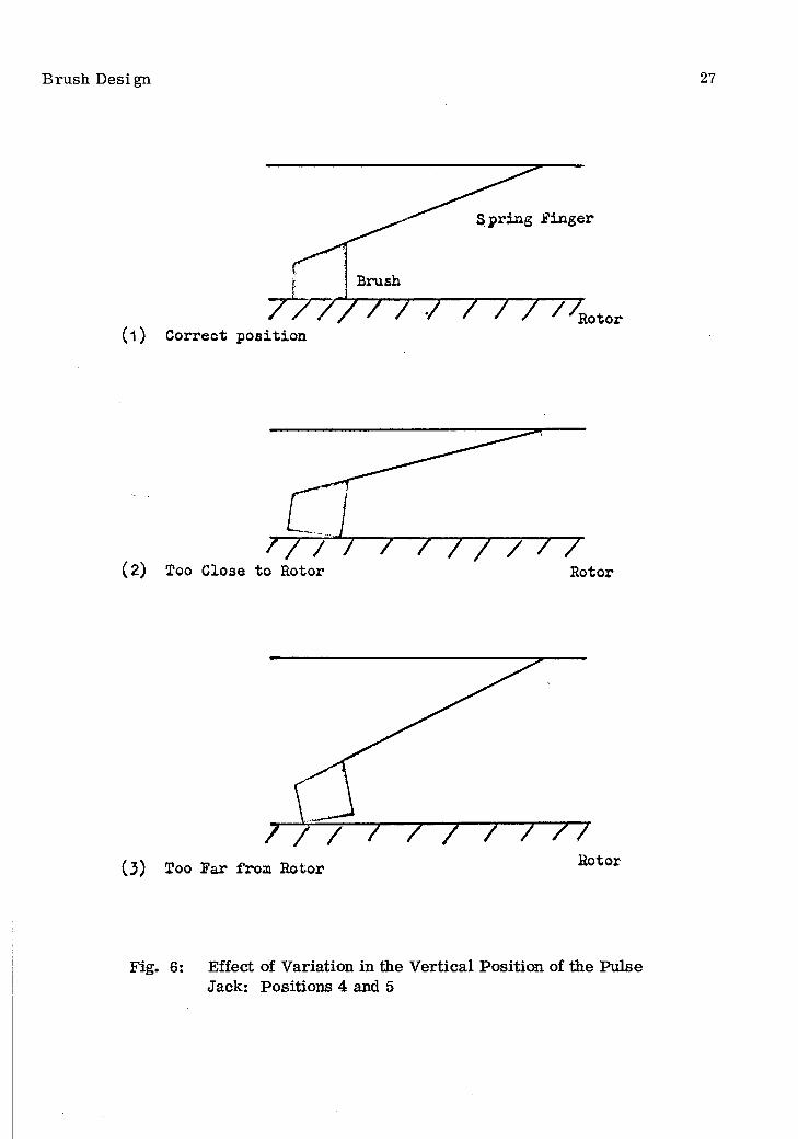
B rush Contact - With refe rence to F igure 17 of M arshall’s rep o rt, slight d ifferences in the v e rtica l position of the pulse jack, when the b rushes a re in contact with the ro to r, would re su lt in the b rushes only making line contact with the ro to r.The principle involved is illu stra ted in F igure '6 of th is rep o rt. The pulse jack would have to be positioned with an accuracy at le as t as good as + 0. 001 in. m o rd e r to obv iate the danger of line contact. We consider it unlikely that th is accuracy could be achieved. It is difficult to put into quantitative te rm s the effect of varying degrees of line contact, the degree probably varying at random between successive pu lses. Howev er, we consider that the p a rticu la r design proposed is fraught with the danger of b ru sh sparking and burning due to line contacts and should be subjected to carefu l te stin g on a suitable rig should it be considered d esirab le to proceed with it fu rth e r fo r o ther reaso n s. The possib ility of having line contacts would not ex ist if sp ira l sp rings, o r som e o ther form of vertically acting spring, w ere used: however, we consider this to be im practicable. Another suggestion is that the b rushes should r e m ain perm anently in contact with the ro to r. This would overcom e the difficulty of line contacts but would lead to overheating of the b rushes and ro to r due to friction lo sse s during no-load periods w ere the machine operated continuously. Should an application for the hom opolar generato r develop which only req u ire s very in te rm itten t pulses, o r pulses sm a lle r than the design value, then it may be of value to cons id e r fu rth er the possib ility of the b rushes being perm anently in contact with the ro to r.
following:In addition to the above m ajor points we draw attention to the
Insulation between Spring F ingers - The can tilever spring fingers a re in c lo se proxim ity to each o ther and it is im portant that there be adequate insulation between them: otherw ise, should they touch, the use of the s e r ie s re s is to rs is n e gated. P rovision for insulation is not shown in Figure 17. 1
Equality of B rush P re s su re - Equality of p re ssu re between b rushes depends on the equality of the can tilever b rush springs. It seem s unlikely that, in p ra c tic e , this type of spring could be readily made and fitted with the high degree of accuracy n ecessary to ensure reasonable equality of p re s su re - say + 10%. G rea te r in equality than th is would lead to a significant varia tion in brush life which would n ecess ita te m ore frequent inspection and m aintenance than would otherw ise be n ecessa ry .
S lip -ring System - No detailed proposals a re m ade1 fo r possible designs •for the s lip -rin g system . We w ill therefo re only comment on some p rincip les involved, though, with reference to the la s t sentence on page 37 of M arsha ll's rep o rt, we
B rush Desi gn 27
( 1 )
Brush/ •/ / / / / / Rotor
Correct position
(2) Too Close to Rotor' / 7 / / / / / / 7 ^ 7
Rotor
/ / / / ' / / / 7~77Rotor(3) Too Far from Rotor
Fig. 6: Effect of V ariation in the V ertical Position of the PulseJack: Positions 4 and 5

B rush Design 28
believe that each system will have to be designed com pletely to enable the re la tive advantages of each to be a ssessed .
T herm al loading - This would be high if the b rushes w ere run on a band one in. o r so wide on each ring. M arshall has calculated a tem pera tu re r ise for the s lip -rin g surface of 230 C. This assum ption of a brush track approxim ately one in. wide is presum ably based on consideration of the gap between the ro to rs (5§ in .) and the use of can tilever b rush mounting s tr ip s as for positions 1 and 8. Provided b ru sh es with sp ira l pull-off sp rings could be used the width of the b rush track on each ring might be approxim ately doubled to about 2 in. and the therm al loading correspondingly reduced.
Spiral sp rings - We recom m end that the use of sp ira l pull-off springs for positions 4 and 5 be considered in conjunction with the s lip -rin g system . This would involve the use of rad ia l b rush holders. The b rush pushers would have to act through the cen tre of the sp rings. The connection to the b rush could not be of the conventional tamped pattern , but would involve the brazing of a copper foil connection which m ust not in te rfe re with free movement of the brush. Magnetic fo rces on the brush and connections would be appreciable and this aspect would have to be investigated (see Section 7 .1).
Number of B rushes - The num ber and size of the b rushes with the s lip ring system could be of the sam e o rd e r as for positions 1 and 8. We suggest approxim ately 600 b rushes p e r position, each approxim ately 0. 4 in. wide x 0. 8 in. thick, a rranged in groups of four b rushes side by side around the s lip -ring .
Th^re is no doubt that the difficulties of b ru sh g ear design for positions 4 and 5 a re severe and w arran t g re a te r attention than has been given to them so fa r. The conditions of operation at the b rush in terface a re s im ila r to those for positions 1 and 8, and le ss spectacu lar than fo r positions 2, 3, 6 and 7: it is perhaps p artly fo r these reasons that the b rushgear design for positions 4 and 5 has not yet been form ulated in sufficient detail. It should be borne in mind that the proposed 'q u a r te r machine te s t ', not involving positions 4 and 5, will neglect what is perhaps the m ost difficult b rushgear design problem on the hom opolar generato r.
7. M agnetic, E lec trica l and Therm al Effects
There a re three effects which it was not possib le to investigate during the experim ental p rogram m e since they will occur only on the hom opolar generato r itse lf. Each has an im portant bearing on the efficient operation of b rushes, and they a re d is cussed here in re la tion to M arsh a ll's proposals fo r b rushgear.
Magnetic, E lec trica l and Therm al Effects 29
7. 1 Interaction between Magnetic Fields and C urren ts in B rushgear
All the b rushgear used on the hom opolar generato r w ill be s itu a ted in a m agnetic field, and in consequence will be subjected to electrom agnetic fo rces during each c u rre n t pulse. One component of force re su lts from in teraction of the c u r ren t in each b rush mounting s trip with the main field of the generato r. The o ther com ponent of fo rce re su lts from interaction between the cu rren t in each b rush and mounting s trip and the ’pinch’ field. The pinch field is induced by c u rre n t flowing in the ro to rs during a pulse, and is in the form of a system of c irc u la r lines of flux concentric with the ro to rs . O ther electrom agnetic fo rces occur due to leakage flux, and c u rre n t flow in conductors adjacent to the brushes; we have not considered these fo rces.
It is c learly m ost im portant that electrom agnetic fo rces do not d istu rb the stab ility of b rush contact during a cu rren t pulse. In calculating the fo rces approxim ately we have used the values of pinch field given in M arshall’s repo rt; we com m ent on th is point la te r.
Positions 2, 3, 6 and 7
The fo rces acting on the b rushes a re re la tive ly sm all - a c irc u m feren tia l fric tion force of 1 .6 lb (8 lb load, y = 0. 2) and a c ircum feren tia l fo rce of 0. 6 lb due to the main field (1, 000 gauss in this region).
A fu rth er force of 2. 8 lb acts rad ially inwards on the c u rre n t carry ing p a rt of the brush mounting s trip due to the pinch field. P a r t of th is fo rce will be applied to the edge of each brush adjacent to that p a rt of the s tr ip carry in g cu rren t, and M arshall’s estim ate of 1.4 lb (ref. 1, page 13) appears reasonable .
These fo rces should not unduly affect contact stab ility with an applied force of 8 lb.
Positions 1 and 8
These b rushes operate in the main field (16, 000 gauss) and in an estim ated pinch field of 5,100 gauss at maximum cu rren t.
The c ircum feren tia l force due to the main field is approxim ately 10 lb p e r b rush , and this w ill tend to tw ist the can tilever mounting s tr ip s . We strongly recom m end that the stab ility of the b rushgear is checked experim entally with th is r e la tively la rg e tran s ien t force of 10 lb applied to the brush.
Pinch fo rces act rad ially inwards on each of the b rush mounting s tr ip s during a cu rren t pulse, and range from 12 lb p e r b rush on the innerm ost track to 24 lb p e r b rush on the ou term ost track . A detail drawing in Figure 15 shows how it is proposed to share the fo rces between brushes by allowing the support s tr ip s to p re ss on one another. This arrangem ent w ill requ ire very carefu l adjustm ent if the

M agnetic, E lec trica l and Therm al Effects 30
loads are to be p roperly equalised. The average additional load on each brush will then be about 15 lb which w ill give r ise to a tran sien t c ircum feren tia l friction force having a maximum value of about 3 lb.
It is c learly im possible to be certa in , without carry ing out experim ents to sim ulate these conditions, w hether this b ru shgear system will give s a tisfacto ry contact under pulse conditions, p a rticu la rly when re v e rsa l of the ro to r is also involved.
Positions 4 and 5
A 'slid e-o u t unit' design involving a total of 15, 840 sm all brushes is one of the p roposals for positions 4 and 5. At each position 22 b rushes a re mounted in each of 360 connection boards (ref. 1, page 36). The la te ra l force on each brush mounting s trip due to the main field is about 1 lb, i. e. 22 lb p e r board, and therefo re som e form of support at both ends of each board appears to be necessa ry . As proposed, the inner ends a re unsupported.
F orces totalling nearly 4 tons act on each set of 7, 920 brushes, and since these fo rces act in opposite d irections in positions 4 and 5, respectively , the ac tuating m echanism m ust be capable of w ithstanding 8 tons during a pulse.
The pinch force is approxim ately 1/3 lb p e r brush .
If radial b rushes and s lip -rin g s a re substituted for the 's lide-ou t' system , using brush holders instead of can tilever s tr ip s , then la te ra l fo rces due to the m ain field will push the b rushes against the sides of th e ir ho lders. Sufficient load m ust then be applied to each brush to overcom e friction between the brush and holder — amounting to approxim ately 2 lb for a 1 cm long brush — and to ensure that a stable contact is m aintained.
In p rac tice a brush is seldom guided perfectly by the sides of its holder, but generally takes up an equilibrium position determ ined by the fo rces which act upon it. Thus, if the b rush is tem porarily constrained by m agnetic fo rces to one side of the holder, it may tilt from its equilibrium position and lose contact over the g re a te r p a rt of its a rea . A s im ila r effect can also occur when the d irection of ro ta tion is reversed . G reat c a re is requ ired in selecting suitable b rush proportions for operation under these conditions w here a loss of contact could cause serious damage, but provided that the length to thickness ra tio is sufficiently sm all, as fo r the o ther proposed brush designs fo r the hom opolar generato r, th is should not be a problem .
'P inch 'F ield
In estim ating the ’Pinch' forces which act on b rushes and leads we have used values fo r the pinch field given by M arshall. These appear to be theore tic a l values based on a sim plified model fo r rad ial cu rre n t flow in a disc, and we

M agnetic, E lec trica l and Therm al Effects 31
a re doubtful w hether these values a re applicable in the im m ediate vicinity of each brush holder. We suggest that the whole question of magnetic fo rces be reconsidered to take into account the physical arrangem ent of the actual b rushgear, and its p o s ition in relation to c u rren t paths in the ro to rs , b rushes, leads and adjacent bu sb ars.
E lectrom agnetic repulsion
E lectrom agnetic repulsion is an effect which is generally negligible in p rac tice but may becom e im portant w here high cu rren ts flow through a brush . Due to the sharp constriction which the cu rren t paths undergo when a b rush contacts a s lip -ring , the two components m utually repel one another. Hohm^ has calculated the magnitude of this effect. Under the p resen t condition, e. g. a b rush 1 cm square carry in g 2000 am ps, we calculate that the repulsion fo rce will vary from about \ oz, assum ing there a re 20 points of contact each 2 x 10”^ cm d iam eter, to about \ lb, a s sum ing that there is a single contact only. Provided that the b rush load appreciably exceeds \ lb, th is effect can be neglected.
7 .2 Voltage G radients
Positions 2, 3, 6 and 7
It is proposed1 that b rushes should operate only over a narrow band on the rim of each ro to r. These bands a re shown shaded in F igure 2. The r e a son for this lim itation is that a voltage gradient ex ists ac ro ss the ro to r periphery due to the fringing flux of the m ain field. Under these conditions the c u rre n t d istribu tion over the section of the b rush is not uniform , taking a tim e average, but becom es concen trated tow ards one side. M arshall has considered this problem and suggests that the potential difference a c ro ss the width of a CM-O brush should not exceed 0. 2 volts, i. e. a potential gradient of 1 V /cm fo r a brush 1 cm wide. He has calculated the c u rren t d istribution in the b rush from the v o ltage-cu rren t ch a rac te ris tic .
A fu rth e r consideration which applies under these conditions is that brushes on different tra ck s within one of these bands work at different po tentials, and cannot therefore be connected together d irec tly without giving r is e to unequal sharing of cu rren t. Suitable b a lla s t (’s e r ie s ’) re s is to r s a re necessa ry to equalise the cu rren ts .
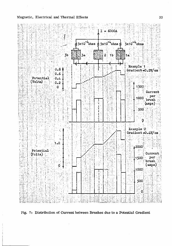
A sim ple calculation has been c a rr ie d out to show how effective these m easures a re in lim iting varia tions in the c u rre n t d istribution between b rushes and within individual b rushes. Three b rushes, 1, 2 and 3, a re assum ed to opera te on separa te track s having a potential difference of 0. 3 volts between them, and the two ou ter brushes have a potential of 0. 2 volts a c ro ss th e ir width. The arrangem ent is shown diagram m atic ally in F igure 7, and rep re sen ts approxim ately the situation in disc D of the homopolar g enera to r. F or sim plicity the ou ter b rushes have been divided into two p a rts , (a), and (b), in o rd e r to estim ate the cu rren t distribution.
Magnetic, E lec trica l and Therm al Effects 32
From experim ents described in Section 5, a vo ltag e-cu rren t c h a rac te ris tic of CM1S has been plotted. Very approxim ately this can be rep resen ted by the equation V = 0. 35 + 2. 5 x 10⁻⁴ I, w here V is in volts and I in am ps. B allast r e s i s to rs a re taken as 5 x lO- ^ ohms and the total cu rren t shared by the th ree b rushes is assum ed to be 6000 am ps.
The c u rre n ts a re found to be d istributed as follows:
B rush 1 (a)(b)
977 amps) 1377 amps) total cu rren t 2354 amps
B rush 2 — total cu rren t 2088 amps
B rush 3 (a)(b)
977 amps) 577 amps) total cu rren t 1554 amps
i. e. the ratio of maximum to minimum cu rren t within a brush o r between b rushes does not exceed 1.7 to 1. Provided that the brush w ear is substantially independent of c u r ren t this cu rren t d istribution can be to lerated . If not, then the use of the self-a ligning b rush holders proposed fo r these positions will re su lt in uneven w ear taking place, with a possible reduction in contact on one side of each outer brush.
Should it be desired to widen the operating band, in o rd e r to r e duce therm al loading of the ro to r, it will be necessa ry to operate b rushes in regions of the ro to r surface having a g re a te r potential gradient than 0. 2 V /cm , and th e re will be a g re a te r potential between b rushes. A very approxim ate calculation has been c a r ried out for three b rushes working with a total potential d ifference of 1.2 volts between them, and a gradient of 0. 4 V /cm w here the ou ter p a ir operate. This arrangem ent is shown in Figure 7.
The d istribution of cu rren ts is as follows:
B rush 1 (a)(b)
956 amps) 1756 amps) total cu rren t 2712 amps
B rush 2 — total cu rren t 2177 amps
B rush 3 (a)(b)
956 amps) 156 amps) total cu rren t 1112 amps
Under these conditions the cu rre n t d istribution is unsatisfactory; B rush 1 c a r r ie s an excessive cu rren t, and the ra tio of maximum to minimum cu rre n t within B rush 3 approached 6 to 1. We would not recom m end operating under these conditions. We cons id e r that the proposed lim it of 0. 2 volt is reasonable for CM1S, as well as CM-O. Setting th is lim it defines the total width of the band over which b rushes may be o p e ra ted and also fixes at 1 cm the m aximum brush width which can be used at the edge of the band.
M agnetic, E lec trica l and Therm al Effects 33
; i ’ . !
6000A
■ ; ! : f _ < '
5x10 ohms
2 1b %
Example 1cm
P o ten tia l(Volts)
: i ' ■
I Current per
f, brush (amps) i:'~
500 ||1
Gradient =0.4V/cm j.
; i I ..' 2000P o ten tia l( /o lts ) Current
perbrush(amps)
: : i . ■. | .: j .
■: i
: ! ■ j ,
Fig. 7: D istribution of C urren t between B rushes due to a Potential G radient
M agnetic, E lec trica l and Therm al Effects 34
B allast re s is to r s a re necessa ry to equalise the cu rren ts in all the b rushes ac ro ss a band, and also to suppress any selective collection by individual b rushes due to in co rrec t loading o r o ther abnorm al conditions. The ba llast res istan ce suggested, which drops 1 volt at peak cu rren t, seem s satisfac to ry . The values of r e sistance could be adjusted fo r individual b rushes to give the optimum cu rren t d is trib u tions for a p a rticu la r d istribu tion of voltage ac ro ss a band, but this would not improve the cu rren t d istribution within individual b rushes, and the gain does not appear to be worth the ex tra com plication.
We suggest that the optimum location of the bands be verified experim entally with the ro to rs of the hom opolar generato r ro tating at full speed. This could be done by using suitable probe b rushes.
It will also be necessa ry to verify that b rushes working in a potentia l gradient w ear reasonably uniform ly ac ro ss th e ir sections and do not overheat at the edge carry ing the h ighest cu rren t density.
Positions 1 and 8
There is no significant voltage gradient.
Positions 4 and 5
Since the voltage gradient on the face of each ro to r will be 1 V /cm a t full speed, the width of the b ru sh es will be severely lim ited. Taking the c rite rio n of 0. 2 volt d iscussed above, the width becom es 0. 2 cm. as proposed by M arshall, and the num ber of b rushes required to c a r ry the peak c u rren t is accordingly g rea t (Section 6. 3)
7 .3 Therm al Loading of R otors and S lip-rings
Positions 2, 3, 6 and 7
M arshall has calculated (ref. 1, Section 5) the tem peratu re r ise which can be expected to take place at the surface of a ro to r during a cu rren t pulse due to friction and e lec trica l lo sse s at the b ru sh -ro to r in terface. Under the operating conditions which have been assum ed, viz. a load of 8 lb p e r b rush , friction coefficient = 0 .2 , voltage drop = 0. 55 volts, cu rren t = 1850 amps max. p e r brush, and total width of band 6 cm, the maximum tem p eratu re r is e is found to be 180 C.
It has been shown by M arshall (ref. 1, Section 6 and 7) that r e peated cycling over a tem pera tu re range of 180 C is likely to induce fatigue fa ilu re in the surface lay ers of the ro to r, and that if cracking is to be avoided the r is e in surface tem peratu re should not exceed about 115 C.
One aim , of the experim ental program m e described in Section 5 of this report, was to determ ine w hether the load on the b rush could be reduced from

Magnetic, E lec trica l and Therm al Effects 35
8 lb to 4 lb, and although the re su lts w ere not conclusive it appeared that under b e tte r m echanical conditions this might be possible, assum ing that magnetic forces would not make it im practicable . F riction lo sses a re halved in this way, and the maximum s u r face tem peratu re therefore reduced.
M arshall has calculated the effect of such a change (ref. 1, Section 7), and finds that the maximum tem peratu re r ise becom es 120 C, which is m ore reasonable .
The calculations apply specifically to disc D, w here the brushes opera te over a band 6 cm wide. On disc A, the band is 8 cm wide and the tem peratu re is reduced correspondingly. However, on d iscs B and C the bands a re only 3. 6 and 3 .8 cm wide, respectively , and the maximum tem peratu res, even with a 4 lb load, a re about 190°C.
A fu rth er facto r which m ust be taken into consideration, is the additional tem peratu re r is e due to rev e rsa l of the ro to rs during a pulse (ref. 1, Section 8). The ro to rs come to r e s t while peak c u rren t is flowing through the brushes, and certa in a re as therefore a re subjected to an additional therm al s tre s s . M arshall e stim ates that the additional tem pera tu re r is e could approach 60°C. This means that som e a re as on d iscs B and C could attain a tem peratu re of 250 C. Even allowing for any approxim ations which have been made in these calculations, it appears that the problem of therm al s tre s s is a c ritic a l facto r in the successful operation of the homo- po lar generato r. We have, therefo re , considered possible ways of reducing this tem p e ra tu re r ise :
(a) Gas cooling of ro to rs and brushes(b) W ater cooling of b rushes(c) W ater cooling of ro to rs(d) Increasing the width of the operating band
(1) by increasing the potential gradient lim it(2) by reducing the fringing flux
(e) Reducing the contact drop
(a) Gas cooling of ro to rs and brushes - During the course of a cu rren t pulse (1. 6 x 10 A peak) nearly 10^ cals would be libera ted at the surface of each disc within 3 seconds, and it would not appear p rac ticab le to ex trac t a reasonable proportion of th is heat in 3 seconds by using a gas as coolant. With a ir the flow ra te s required would be sev era l million cubic feet p e r minute.
(b) W ater cooling of b rushes - The la rg e num ber of b rushes and th e ir need for r e newal at fa irly frequent in te rva ls m akes d irec t w ater cooling of individual brushes im p racticab le .
(c) W ater cooling of ro to rs - M arshall has c a rrie d out experim ents on a 2 in. d iam e te r te s t ro to r which was w a ter cooled by flooding its su rface with w ater, and rep o rts
Magnetic, E lec trica l and Therm al Effects 36
that the cooling was efficient and did not in te rfe re with b rush operation.
The m ost serious objection to w ater cooling the hom opolar g enera to r in a s im ila r m anner is the difficulty of ensuring that lift due to hydrodynamic lubrication of the b rushes does not occur. If some b rushes happen to be tilted against the d irection of motion at the instant they come into contact with the ro to r surface then lift can readily take place, wi:h a consequent reduction in the total num ber of b rushes available to c a rry the c u rrent and the possibility that th is w ill cause overloading and breakdown of the rem ainder.
Further objections to w ater cooling are , f irs t, the possib ility that co rrosion w ill occur, second, the difficulty of m aintaining insulation between d iscs, and finally, the necessity of having a tank round the ro to rs to catch the w ater flung off. The total pumping ra te required would be severa l hundred gallons p e r minute. We consider that fu rth er investigation would be required before it would be possib le to give a final a ssessm en t of w ate r cooling.
(d) Increase the width of the operating band -
(1) by increasing the potential gradient lim it:
The effect of increasing the potential gradient from 0. 2 to 0 .4 v o lts /cm has been d e s cribed in Section 7. 2, but does not seem to be a p rac tica l solution since the cu rre n t distribution is then very non-uniform . M arshall has suggested that b rushes \ cm wide could be used to enable the operating band to be widened. It would be possib le in this way, but at the expense of m echanical com plication, to nearly double the band widths on d iscs B and C, and with a 4 lb b rush load bring the tem peratu re r is e c lose to the lim iting value. This suggestion is worth fu rther investigation.
(2) by reducing the fringing flux:
We have discussed with Mr. J . Blarney of A. N. U ., the possib ility of using som e form of m ignetic shielding to reduce the potential gradients on the ro to rs . One possib ility is to cut a deep slot in the ro to r surface, the sides of which m agnetically shield the bottcm of the slot, which form s the working track fo r the b rushes. However, m achining the ro to r is undesirable, the b rush track is then inaccessib le , and the design of ths b rushgear would need com plete revision. An a lternative method is to surround the tru sh g ea r with a hollow magnetic shield in the form of an annulus. This again in terferes with access to the b rushgear. In addition, severe magnetic fo rces act on the shield; Mr. Blarney has calculated that this might be about 40 lb p e r inch of shield.
A method not d iscussed at C anberra is the possib ility of fitting magnetic shields, of the type shown in F igure 8 adjacent to the b rushgear. We suggest that this is w orthy of further consideration.
(e) Reducing the contact drop - If the contact drop of the b rushes could be reduced then the maximum tem peratu re would also decrease . There is only one known a tm o spheric condition in machine p rac tice w here an abnorm ally low contact drop may be
M agnetic, E lec trica l and Therm al Effects 37
obtained ’ ’ ; th is is in synchronous condensers w here a hydrogen atm osphere is used fo r cooling purposes. Under these conditions a low er contact drop and a significant inc re a se in b rush life a re usually obtained. We have no experience of operating m etallic b rushes at high c u rren t densities under these conditions, but it seem s unlikely that the reduction would be as g rea t as fo r the non-m etallic b rushes norm ally used.
Positions 1 and 8 - No potential gradient
Positions 4 and 5
Potential gradient 1 V /cm at full speed. The lim itation in brush width has been d iscussed in Section 7. 2
8. Maintenance
The following points re la te to m aintenance of the brush and slip -rin g sy s tem .
S lip -ring m aintenance - The s lip -rin g su rfaces may possibly be damaged during operation . Superficial damage, such as light burning o r sooting, may be rem oved by the application of Carborundum paper (300 grit) with the machine rotating. However, when applied m anually, this will eventually lead to 'w aviness' and o ther departu res from tru th . We therefore recom m end that the su rfaces be finely turned with a d iamond tipped tool a fte r not m ore than th ree applications of abrasive paper. It should be noted that if a satisfac to ry uniform 'film ' develops on the s lip -rin g su rfaces then th is should not be removed at any tim e - including when the b rushes a re changed.Any deep dam age to the rings should be removed by turning as soon as possible after being observed, since such damage usually will rapidly become w orse during op era tion.
B rush bedding - On conventional m achines it is common p rac tice to 'bed in' the b rushes by m eans of abrasive paper o r ab rasive cloth o r by m eans of a bedding stone; i. e. the b rush contact su rfaces a re artific ia lly worn p r io r to use so that they make intim ate and uniform contact with the com m utator o r s lip -rin g . We recom m end that, in the case of the homopolar generato r, the b rushes a re not bedded in with abrasives since this should not be necessary - assum ing that the b rushes a re produced with conta c t su rfaces having approxim ately the sam e curvature as the s lip -rin g s (in the case of positions 2, 3, 6 and 7 the b rushes need 'p re lim in a ry ' bedding to produce the c o rre c t cu rva tu re - see Section 6 .1 ). The se r ie s re s is to r s will a ssu re uniform d is trib u tion of cu rre n t between brushes during initial running, and the in itial ra te of brush w ear, of the o rd e r of 10“3 in. p e r pulse, should be sufficiently high to cause the b rushes to bed satisfac to rily within about ten pu lses. We recom m end that the f ir s t few applications of the b rushes, for bedding purposes, be without cu rren t.
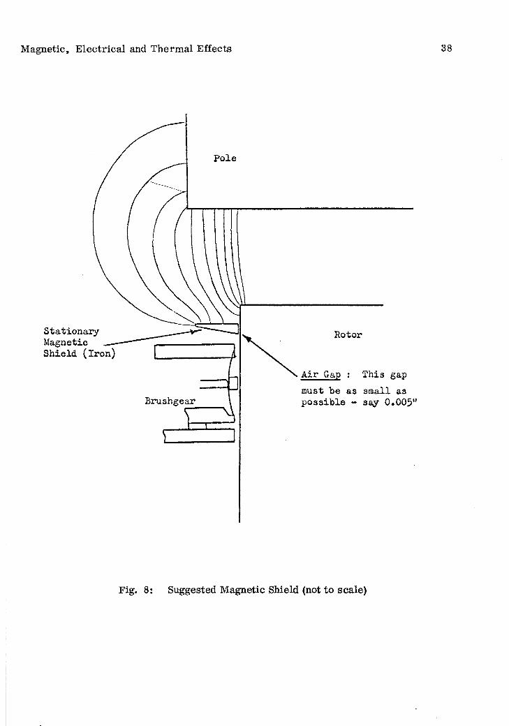
M agnetic, E lec trica l and Therm al Effects 38
StationaryMagnetic __Shield (iron)
Rotor
Air Gap : This gap
must be as small a3Brushgear
Fig. 8: Suggested M agnetic Shield (not to scale)
M aintenance 39
B rush w ear dust - It is unlikely that the norm al ventilation of the hom opolar generato r will c a rry away the w ear dust from the b rushes, p articu la rly since the m ajority of th is will be copper dust. It will therefore be n ecessary to rem ove this dust at regu lar in tervals. These periods will depend on the frequency with which the machine is used: it is suggested that the dust be removed at le a s t twice as frequently as the b rushes a re changed. Using M arsha ll’s proposed brush design figures (Table 1), the volume of m ate ria l worn during the life of the b rushes (say 60% of actual b rush volume) would be nearly 200 cubic in. This dust should e ither be blown out of the machine, removed by vacuum cleaning, o r by o ther suitable techniques.
C leanliness of a ir - The a ir supply to the b rushgear should be m aintained clean: inp articu la r, it should be free from any significant amount of oil m ist from the bearings o r from the com p resso rs supplying a ir to the a ir bearings. If necessary , and if possible, f ilte rs should be used to ensure c lean liness. Extrem ely sm all percentages of oil from the bearings a re norm ally encountered in the vicinity of la rge e lec trica l m achines and do not harm brush contact perform ance. However, we observed that the pole faces and o ther p a r ts of the hom opolar generato r had a substantial oily film on them, which we understood came from the bearings. This would be considered to be highly unsatisfactory on a conventional machine. The p resence of unduly large concentrations of oil spray in the vicinity of cum m utators and s lip -rin g s on conventional m achines is a recognised cause of b rush contact irreg u la ritie s leading to dam age of the contact su rfaces . We recom m end that the c leanliness of a ir in the vicinity of the s lip -rings be carefu lly considered. In addition to oil, the p resence of abrasive dust - e .g . cem ent dust - is another cause of trouble.
C leanliness of s lip -rin g s - When fitting new brushes, o r undertaking o ther m ain tenance work, it is m ost im portant that men working on the machine should not d irty the s lip -rin g su rfaces - p a rticu la rly with oily finger m arks and sm udges. Subsequently, these a re likely to lead to burnt patches on the s lip -rin g su rfaces. If the ro to r is removed from the machine for m aintenance we recom m end that the s lip -rin g su rfaces be covered with suitable paper to keep them clean. On no account should oil o r o ther d ir t be rem oved with carbon te trach lo ride . This solvent destroys brush film s and induces high ra te s of b rush w ear even in very sm all quantities. The m ost suitable solvent for removing oil is probably petroleum ether.
Changing brushes - It should not be n ecessary to change all the b rushes on a p a rticu la r s lip -rin g sim ultaneously. The s e r ie s re s is to rs will prevent any significant cu rren t selection between old and new brushes. Therefore, when the machine is in regu lar use, if it is m ore convenient to change a fraction of the b rushes at regu lar in tervals, ra th e r than all the brushes at one tim e, then this is perm issib le .
Hold-off springs - We recom m end that an inspection system be devised for system atically and regularly checking the efficiency of all b rush hold-off springs: all weak springs (spring fingers) should be replaced without delay. Spring fa ilu re s a re likely to be associated with rapid b rush w ear and, subsequently, damage to both the spring and-si ip -ring when the brush is worn away and the spring contacts the slip -ring .
9. Conclusions 40
We have d iscussed in this rep o rt the re su lts of the experim ental p rog ram m es c a rrie d out to a sse ss the perform ance of solid b rushes under conditions asso c ia ted with the duty cycle of the homopolar generato r. We have also com m ented on the proposals made by Mr. R. A. M arshall1 and have made many detailed recom m endations on the use of b rushes. Our general conclusions a re sum m arised below.
9. 1 Design and Perform ance D etails
Selection of B rush Grade:
From the experim ental re su lts we conclude that CM1S is the m ost suitable b rush grade for tr ia l on the homopolar generato r.
Operating conditions:
In experim ents sim ulating the cu rre n t density, surface speed, and b rush load for the homopolar generato r, CM1S and certa in o ther g rades with a high copp e r content behaved reliably without sparking and without damaging the surface of the te s t ro to r. Steady readings of friction, w ear and contact drop w ere obtained. We conclude that re liab le brush operation may be expected under these te s t conditions. However, the effects of magnetic fo rces and voltage gradients w ere not m easured , and the m easurem ents of ro to r heating w ere for ra th e r different conditions than on the homo- po lar generato r. Magnetic fo rces and ro to r heating a re m ajor problem s, the effects of which m ust finally be m easured on the hom opolar generato r since they cannot read ily be sim ulated on te s t rigs: in p a rticu la r, the tran s ien t nature of the magnetic fo rces affecting b rush stability does not appear to have been considered in detail at C anberra. With M arshall's proposed design we consider that the effect of potential g radients, r e sulting in the non-uniform distribution of cu rren t, should not be a serious problem .
B rush life:
The minimum brush life will probably occur at positions 2, 3, o and 7, and from the te s t re su lts would appear to be of the o rd e r of 1000 pulses. We therefore conclude that brush life should not be a m ajor problem , provided that m echanical stability is maintained.
Therm al effects:
The problem s associated with therm al s tre ss in g of the ro to r have been discussed in Section 7 .3 . Assum ing that an unlimited life is required from the ro to r without fatigue-cracking of the su rfaces taking place, i. e the maximum tem pera tu re cycle during a pulse not exceeding 115°C , then steps m ust be taken e ither to reduce the total dissipation of heat during a pulse, o r to force cool the ro to r.
In the case of positions 2, 3, 6 and 7, we consider that the most prom ising way of reducing the total d issipation would be to reduce the b rush load, and we recom m end that this be tried experim entally on the hom opolar generato r. On d iscs

C onclusions 41
A and D the maximum tem p era tu re approxim ates to the requ ired lim it if the load is reduced to 4 lb p e r brush, assum ing the ro to rs do not rev e rse , but fu rth e r m easures a re needed for d iscs B and C. M arshall's proposal to use b rushes \ cm wide on the ou te r tra ck s is w orth investigating, as also is the possib ility of using magnetic shields to reduce the potential g radient. The operational lim its in the case of ro to r rev e rsa l appear to requ ire fu rth e r consideration.
We do not consider that forced cooling of the machine in o rd e r to lim it the tem pera tu re r is e during a pulse will be p rac ticab le (Section 7.3). However, forced a ir cooling to a s s is t in lim itation of the ultim ate tem peratu re r is e of the ro to r appears to be p rac ticab le , and desirab le , it the machine is to be operated continuously. We do not consider that the advantage of m ore effective cooling gained by using a hydrogen atm osphere would offset the resu ltan t complex m odifications requ ired at this advanced stage in the construction of the m achine. We have no inform ation on the perform ance of high copper content b rush grades for these operating conditions in a hydrogen atm osphere; however, though the brush contact drop in hydrogen is norm ally reduced in the case of carbon and graphite g rades, we would not expect it to be reduced by a significant amount fo r copper grades under the conditions considered.
B rushgear design:
The proposed1 type of b rushgear fo r positions 2, 3, 6 and 7 should give satisfac to ry perform ance subject to our c ritic ism s on points of detail (6. 1). In the case of positions 1 and 8, the magnetic fo rces a re very large, approxim ately 10 lb p e r b rush acting circum feren tia lly and between 12 and 24 lb p e r brush acting ra d ia lly. The effect of these fo rces on brush stability and cu rren t collection for the p roposed design has not yet been investigated at C anberra; this p resen ts a form idable problem which will have to be surm ounted if the m achine is to operate sa tisfac to rily . We cons id e r the ’slide out unit' design for positions 4 and 5, requiring 15, 840 brushes, to be im practicab le in the form proposed because of m anufacturing and m aintenance difficultie s , excessive magnetic fo rces on the individual b rush springs, and because of the danger of line contacts due to varia tions in the v e rtica l position of the pulse jack. The a lte rnative s lip -rin g design for positions 1 and 8 also involves many difficulties. We recom m end that both types of design be investigated fu rth er in much g re a te r detail than hitherto; there is no doubt that the design problem for positions 4 and 5 is very difficult and its detailed solution, inevitably involving much experim ental work on prototype designs, will requ ire g rea t effort.
Maintenance:
M aintenance of b ru shgear on the hom opolar generato r would be a m ajo r problem in te rm s both of the amount of work involved and the degree of p ra c tical skill and ca re requ ired by the m aintenance w orkers. However, we consider that m aintenance would involve no in trinsic technical d ifficulties.
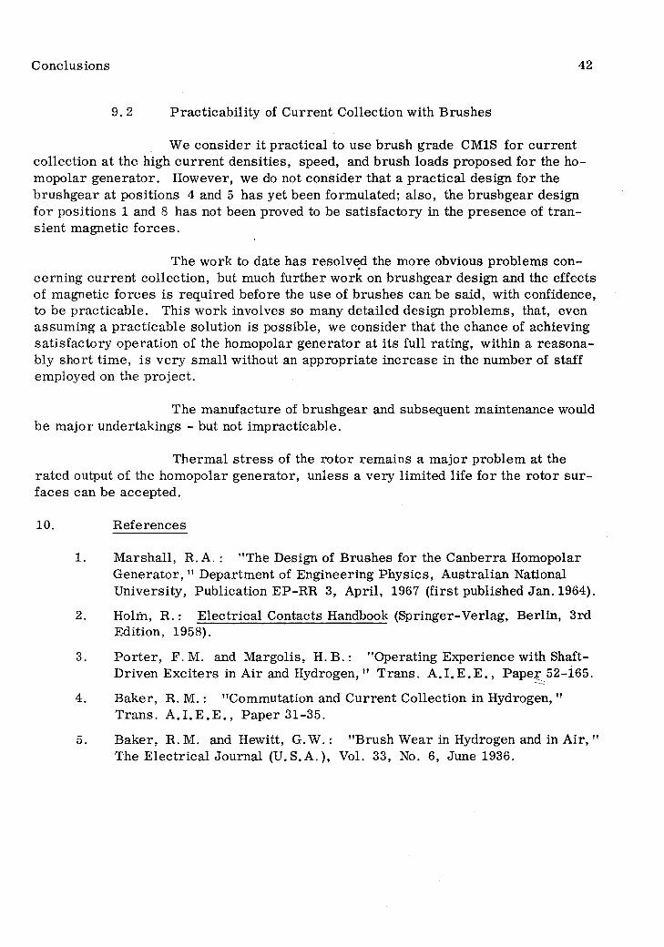
Conclusions 42
9. 2 P rac ticab ility of C urren t Collection with B rushes
We consider it p rac tica l to use b rush grade CM1S for cu rren t collection at the high c u rre n t densities, speed, and brush loads proposed for the ho- m opolar g enera to r. However, we do not consider that a p rac tica l design for the b rushgear at positions 4 and 5 has yet been form ulated; also, the b rushgear design fo r positions 1 and 8 has not been proved to be sa tisfac to ry in the presence of tra n sien t m agnetic fo rces.
The w ork to date has resolved the m ore obvious problem s concerning c u rren t collection, but much fu rther work on b rushgear design and the effects of magnetic fo rces is requ ired before the use of b rushes can be said, with confidence, to be p rac ticab le . This w ork involves so many detailed design problem s, that, even assum ing a p rac ticab le solution is possible, we consider that the chance of achieving satisfac to ry operation of the hom opolar generato r at its full rating, within a reasonably short tim e, is very sm all without an appropria te increase in the num ber of staff employed on the p ro jec t.
The m anufacture of b rushgear and subsequent m aintenance would be m ajor undertakings - but not im practicable.
Therm al s tre s s of the ro to r rem ains a m ajor problem at the ra ted output of the hom opolar generato r, unless a very lim ited life fo r the ro to r s u r faces can be accepted.
10. R eferences
1. M arshall, R. A .: "The Design of B rushes for the C anberra HomopolarG enera to r, " D epartm ent of Engineering Physics, A ustralian National U niversity , Publication EP-RR 3, A pril, 1967 (firs t published Jan. 1964).
2. Holm, R. : E lec trica l Contacts Handbook (S pringer-Verlag, Berlin, 3rdEdition, 1958).
3. P o r te r , F. M. and M argolis, H . B . : "O perating Experience with Shaft-Driven E x cite rs in A ir and H ydrogen," T rans. A . I . E . E . , P ap er 52-165.
4. B aker, R. M. : "Commutation and C urren t Collection in Hydrogen, "T rans. A . I . E . E . , P aper 31-35.
5. B aker, R. M. and Hewitt, G. W .: "B rush W ear in Hydrogen and in A ir, "The E lec trica l Journal (U.S.A.) , Vol. 33, No. 6, June 1936.
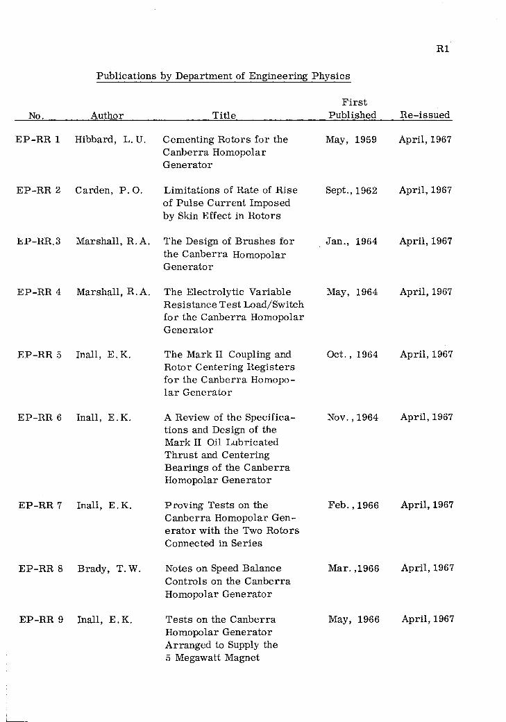
RI
P ub lications by D epartm en t of E ng ineering P h y sics
No._________ A uthor
E P -R R 4 M a rsh a ll, R. A.
E P -R R 5 Inall, E . K.
E P -R R 6 Inall, E. K.
E P -R R 7 Inall, E . K.
E P -R R 8 B rady, T. W.
E P -R R 9 Inall, E. K.
T itle
The E lec tro ly tic V ariab le R esis tan ce T e s t L oad/Sw itch fo r the C an b e rra H om opolar G en era to r
The M ark II Coupling and R o to r C en tering R e g is te rs fo r the C an b e rra H om opo- l a r G en era to r
A Review of the S pec ifica tions and D esign of the M ark II Oil L ub rica ted T h ru s t and C en tering B earin g s of the C a n b e rra H om opolar G en era to r
P rov ing T es ts on the C a n b e rra H om opolar G ene ra to r w ith the Two R o to rs Connected in S e rie s
Notes on Speed B alance C on tro ls on the C an b e rra H om opolar G en era to r
T e s ts on the C an b e rra H om opolar G en era to r A rranged to Supply the 5 M egawatt M agnet
F i r s tP u b lished R e -issu e d
May, 1959 A pril, 1967
Sept., 1962 A pril, 1967
Jan ., 1964 A pril, 1967
May, 1964 A pril, 1967
Oct. , 1964 A pril, 1967
Nov. , 1964 A pril, 1967
F e b . , 1966 A pril, 1967
M ar. ,1966 A pril, 1967
May, 1966 A pril, 1967
E P -R R 1 H ibbard, L. U. C em enting R o to rs fo r theC an b e rra H om opolar G en era to r
E P -R R 2 C arden , P . O. L im ita tions of R ate of R iseof P u lse C u rre n t Im posed by Skin E ffect in R o to rs
E P -R R .3 M arshall, R. A. The D esign of B ru sh es fo rthe C an b e rra H om opolar G en era to r

Publications by D epartm ent of Engineering P hysics (C ont.) R2
No. Author TitleF ir s t
Published
EP-RR 10 Brady, T .W . A Study of the P erfo rm ance of the 1000 kW M otor Gene ra to r Set Supplying the C anberra Homopolar Gene ra to r Field
June, 1966
EP-RR 11 Macleod, I.D.G. Instrum entation and Controlof the C anberra Homopolar G enerator by On-Line Computer
EP-R R 12 Carden, P .O . M echanical S tre sses in an Infinitely Long Homogeneous B itte r Solenoid with Finite External Field
O c t., 1966
J a n . , 1967
EP-R R 13 Macleod, I.D.G. A Survey of Isolation A m pli- Feb. , 1967fie r C ircuits
EP-R R 14 Inall, E .K . The M ark III Coupling for Feb. , 1967the R otors of the C anberra Homopolar G enerato r
EP-RR 15 Bydder, E. L. On the Integration of M ar. ,1967Liley, B .S. "B oltzm ann-L ike"
Collision In teg ra ls
EP-R R 16 Vance, C . F . Simple T h y ris to r C ircu its M ar. ,1967to P u ls e -F ire Ignitrons fo r C apacitor D ischarge
EP-R R 17 Bydder, E. L. On the Evaluation of E lastic Sept. ,1967and Inelastic Collision F re quencies fo r H ydrogenic-Like P lasm as
EP-R R 18 Stebbens, A.Ward, H.
The Design of B rushes for the Homopolar G enerato r at The A ustralian National U niversity
M ar. ,1964
R e-issued
A pril, 1967
A pril, 1967
S e p t., 1967

Copies of this and other Publications (see list inside) of the Department of Engineering Physics may be obtained from:
The Australian National University Press,P.O. Box 4, Canberra, A.C.T., 2600. Australia.
Price: $ A 1.00
Copyright N ote: Reproduction of this publication in whole or in part is not allowed without prior permission. It may however be quoted as a reference.