The design of a rotary engine
68
Transcript of The design of a rotary engine

t


THE DESIGN
OF A
ROTARY ENGINE
BY
FREDERICK AUGUSTUS BROOKS
THESIS
FOR THE
DEGREE OF BACHELOR OF SCIENCE
IN
ELECTRICAL ENGINEERING
COLLEGE OF ENGINEERING
UNIVERSITY OF ILLINOIS
1917


UNIVERSITY OF ILLINOIS
THIS IS TO CERTIFY THAT THE THESIS PREPARED UNDER MY SUPERVISION BY
F.r.e.dexi.Qk . .Angustua . . .Br.Q .0.fca *
entitled ,T.he...De.aig;ri...Qf ...a..Horary. Engim,
IS APPROVED BY ME AS FULFILLING THIS PART OF THE REQUIREMENTS FOR THE
DEGREE OF ...BaQ&elpX..Qf ...^
Instructor in Charge
HEAD OF DEPARTMENT OF

Digitized by the Internet Archive
in 2013
http://archive.org/details/designofrotaryenOObroo
ji. „ 1
1.
CONTENTS,Page,
Chapter I INTRODUCTION 3
1. STATE OP THE ART 3
(a) Principle of the Augustine Engine 3
(b) Present Positive Rotary Blowers 3
(c) Gear Pumps 4
2. IMPORTANCE OP ROTARY MACHINES 4
(a) Longevity 4
(b) Absence of Vibration 4
(c) Possible Lightness 5
3. DEVELOPMENT OP THIS ROTARY MACHINE 5
(a) Applicability of the Grooved Rotor 5
(b) Positive Action with Rotary Valve 5
(c) Serviceability wherever Pistons are used 6
Chapter II MECHANICAL CONSTRUCTION OP UNIT 7
1. REQUIREMENTS 7
(a) Unidirectional Motion 7
(b) Circular Motion 7
(c) Continuous Rotation 7
(d) Positive Action 7i
2. DEVELOPMENT 7
. 3. RESULT 11
Drawing of Unit, plate A 12
Chapter III OPERATION OP UNIT 14
1. CRITICAL POINTS OP LIMITING VOLUME 14
2. INTAKE 15
3. COMPRESSION 16
4. EXHAUST AND EXPANSION 16
I ChaDter IV
CONTENTS (continued)
COMBINATION OP UNITS^X | imp WW A» W*l NX A> WAV -«» A '
2.
Page.17
1 . DIVISION OP CYCLE 17
2. RELATIVE POSITION 17
(a) Cvcle Relation 17
(b) Mechanical Relation\ »X / A*<k NX VlilAUJi NXOO JL; Jk WNX J>M VJ> A» NXA A 18§ NX
3 . COMPOUNDING-• •Jp' NX >A* >X N» Al AX at* X 1 N4 18
Chapter V COMPLETED GAS ENGINE 20
1 . INTAKE 20*j* ^x
2 . COMPRESSION 21
3. TRANSFER OP COMPRESSED CHARGE 21
4. EXPANSION 23
(a) Single Expansion 23
(b) Compound Expansion 23
5. EXHAUST 24
6. SIMULTANEOUS ACTIONSNX V KX A*iuw J,A* * NX fc-X X* NX X A- NXA *—
'
24
Photographs of Completed Engine 25
ChaDter VI PRACTICAL CONSIDERATIONS 26
1 . MECHANICAL PIT 26
2. COMPRESSION 26
(a) Variation with Soeed\ V ss*A Jh Bl W*i» >XA A » A» WAA ^—' NX >X >X^*i 27
( b ) Maintenance 27
3. OPERATION„X V W A — -a* VAA A A> VAI 27
(a) Without Comoound Unit 27
(b) Complete 28

CHAPTER I
INTRODUCTION.
3.
1. STATE OP THE ART. Numerous attempts have been made to produce
a rotary engine with little success hitherto. In any book on
Kinemetics of Machinery several arrangements are shown, each
workable but not developed into a practical machine. Of all these
types the only one on the market today is the Augustine Rotary
Steam Engine.
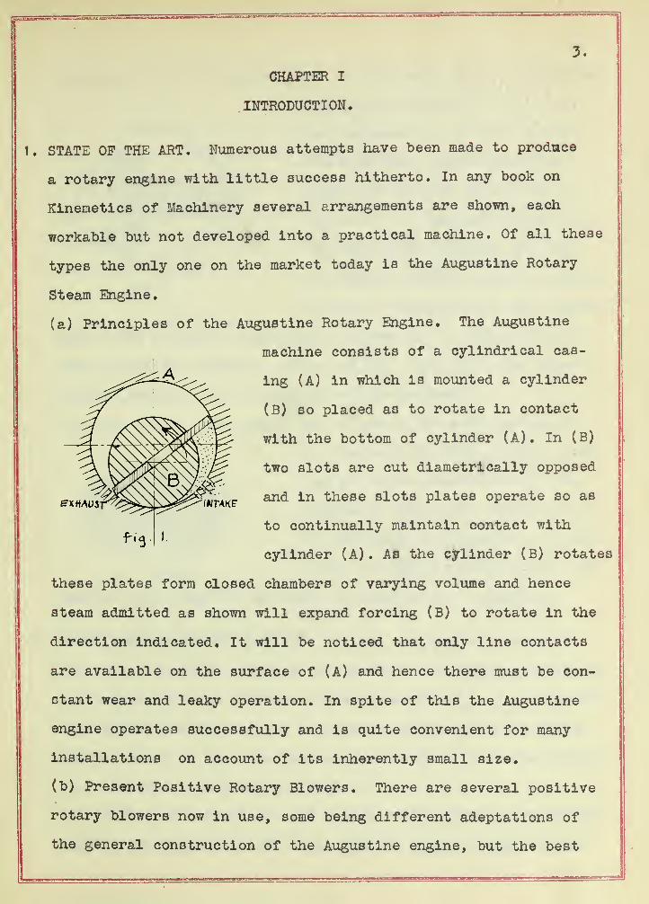
(a) Principles of the Augustine Rotary Engine. The Augustine
machine consists of a cylindrical cas-
ing (A) in which is mounted a cylinder
(B) so placed as to rotate in contact
with the bottom of cylinder (A). In (B)
two slots are cut diametrically opposed
and in these slots plates operate so as
to continually maintain contact with
cylinder (A). As the cylinder (B) rotates
these plates form closed chambers of varying volume and hence
steam admitted as shown will expand forcing (B) to rotate in the
direction indicated. It will be noticed that only line contacts
are available on the surface of (A) and hence there must be con-
stant wear and leaky operation. In spite of this the Augustine
engine operates successfully and is quite convenient for many
installations on account of its inherently small size.
(b) Present Positive Rotary Blowers. There are several positive
rotary blowers now in use, some being different adeptatlons of
the general construction of the Augustine engine, but the best
4.
A '*
fia.St.
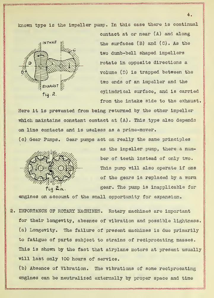
known type is the impeller pump. In this case there is continual
contact at or near (A) and along
the surfaces (B) and (C). As the
two dumb-bell shaped Impellers
rotate in opposite directions a
volume (D) is trapped between the
two ends of an impeller and the
cylindrical surface, and is carried
from the intake side to the exhaust.
Here it is prevented from being returned by the other impeller
which maintains constant contact at (A). This type also depends
on line contacts and is useless as a prime-mover,
(c) Gear Pumps. G-ear pumps act on really the same principles
as the Impeller pump, there a num-
ber of teeth instead of only two.
This pump will also operate if one
of the gears is replaced by a worm
ftq.&a.. gear. The pump is inapplicable for
engines on account of the small opportunity for expansion.
IMPORTANCE OP ROTARY MACHINES. Rotary machines are important
for their longevity, absence of vibration and possible lightness.
(a) Longevity. The failure of present machines is due primarily
to fatigue of parts subject to strains of reciprocating masses.
This is shown by the fact that airplane motors at present usually
will last only 100 hours of service.
(b) Absence of Vibration. The vibrations of some reciprocating
engines can be neutralized externally by proper space and time

5.
relation of parts, but internally the tendency exists and ulti-
mately will cause the engine to fail. A rotary engine can be
built inherently balanced in every part and the only strains will
be due to the centrifugal and power forces.
(c) Possible Lightness. In rotary machines the crank is integral
with the equivalent piston and hence all conectlng mechanisms are
done away with. This makes a rotary machine inherently lighter
and far more compact than a reciprocating engine of the same
strength and materials.
3. DEVELOPMENT OP THIS ROTARY MACHINE. The rotary described in this
thesis was developed step by step, not by derivation from other
rotary machines, but in accordance with the fundamentals of mechan-
ics and gas engine design theory. The complete machine is strict-
ly an adaptation of the cycle of the present reciprocating inter-
nal combustion engine to a true rotary engine.
(a) Applicability of the Grooved Rotor. The machine depends upon
a grooved rotor mounted in a close fitting cylindrical casing.
The annular grooves are stopped off at chosen places by lugs set
therein, thus forming closed annular sections or compartments.
(b) Positive Action with Rotary Valves. Rotary disks mounted in
the casing project into these compartments deviding them into
chambers of variable volume as the rotor revolves. The lugs pass
the disks thru the cavities cut out for them in these rotating
disks or valves. The lug approaching the rotary valve is equiva-
lent to a piston toward the cylinder head. When the lug passes thru
the valve it is as if the cylinder head opened, allowing the piston
to pass thru; and closed after it. Then as the lug moves away it

6
is equivalent to the piston receding. Hence, the operation is
positive like that of the ordinary piston in a cylinder,
(c) Servicability Wherever Pistons are Used. The similarity
makes this rotary construction applicable to every case in which
pistons and cylinders are now used . Furthermore, the valve action
for pumps and motors is greatly simplified. The advantages of a
rotary machine over a reciprocating machine are well recognized
by engineers.


7.
CHAPTER II
MECHANICAL CONSTRUCTION OP UNIT,
Every engine is composed of one or more units of fundamental
parts, consisting of the cylinder, piston, connecting rod, and
crank in a gas or steam engine, or of separate stages in a steam
turbine; and the functions, motions, and forces occuring in the
several units combine in the polyunit machine to produce the de-
sired flow of power. When an engine must conform to certain re-
quirements it is desirable, tc have each unit separately exhibit
these requirements.
1 .REQUIREMENTS. By definition a true rotary engine must have:
(a) Unidirectional Motion. The prime object of a rotary machine
is to obviate strains and mechanical drag caused by the over-
coming of the inertia of reciprocating masses.
(b) Circular Motion. Any non-circular motion is equivalent to
some combination of circular motions of different speeds or of
circular and reciprocal motion, as may be shown by resolving into
primary components any complex motion.
(c) Continuous Rotation. This is necessary to keep the inertia
of the rotating parts from producing effects similar to those
caused by reciprocating masses. However, if the rotating motion
is continuous, but not uniform, this same effect will act as a
flywheel and be quite advantageous in making the rotation constant.
(d) Positive Action. The machine under consideration is a rotary
adaptation of the cycle of a reciprocating gas engine. If not
positive, the engine would be closely analogous to some type of
turbine based on another distinct theory.
2. DEVELOPMENT. To develop the theory of action and the construction


8.
of one engine unit in accordance with the rotary engine require-
ments just presented, the action of the molecular pump will be
described first. It consists of a grooved cylinder rotating about
its axis at a high speed, mounted in a close fitting cylindrical
casing from which, at one point, a block extends down into the
groove separating the intake and exhaust ports. This machine
conforms to the first three require-
ments; but its action is not positive
i.e., there is a free passage from
exhaust to intake ports which is
overcome merely by the extreme
rotating speed exceeding the molecular velocity of the gas.
If a lug (A) were fixed in the rotor there would no longer be a
fia.5.
free path between ports, but if this machine is to rotate there
must be some means of allowing the
lug (A) to pass thru the block (B)
without destroying the function of
(B). This can be accomplished by
making (B) movable radially, and
synchronizing its removal and replacement with the passage of (A)
past that point. This, however, brings in the objectionable
feature of a reciprocating part, so to obviate this a rotating
disk making rolling contact with the bottom of the groove is
substituted for block (B). In this
disk a cavity is cut of just suffi-
cient size to let the lug (A) pass
thru as both rotate. Now this forms
a positive rotary element conform-


9.
ing in a rough way to all the requirements. As will be shown
later, it is important to make the cavity in the disk or rotary
valve as small as possible, likewise to make the block (A) of
the maximum volume which can pass thru the rotary valve. This
requires the determination of the paths of the conflicting edges.
The best shapes are those in which the corners of the lug scrape
the entire surface of the valve cavity, and the corners of the
cavity follow closely the contour of the lug.
These curves are determined graphically. Securing a rolling
contact of the rotary valve on the bottom of the groove by choos-
ing equal radii and velocities, the angular displacement of one
will be equal but in the opposite direction to the displacement
of the other. On this basis the path of any point on one can be
determined with relation to the other by the following method,
as shown on the next page.


fi,. 6.
a b = travel of corner of lug.
a"b"=: angular displacement laid off = a'b 1
.
,% b d = distance of point b on circ. b from center line ofstarting point on the periphery,
a c = travel of point.
a M c M= angular displacement laid off a'c'
,\ c e = distance on circ, c of point c from center line ofstarting point on the periphery.
By taking a large number of points and replotting with
coincident center lines there is produced the desired curve
ABC, This definitely fixes the shape of the cavity, since
it must be symmetrical, the angular separation C'Cj[ being
equal to F'Fj the angular length of the top of the lug.

11.
The same method can be used in determining the shape of the lug,
1 1'
^_
—
rf g = travel of comer of cavity.
f'g' = angular travel of rotor = f g.
.\ g i = distance of point g on circ. g from center line of f.
f h = travel of corner of cavity.
f'h'F angular travel of rotor = f h.
\ h'h= distance of point h on circ.h from center line of f
•
Taking a large number of points, the curve can be determined
very accurately and the lug constructed with symmetrical curves
for opposite sides, which are separated angularly by the distance
P'p; «qual to F'P| of fig. 6.
3. RESULT. Applying these curves and using appropriate dimensions
the accompanying drawings, plate A, show a unit adapted to rotary
engines. The sides of the grooves can be made thick, as shown,
and equipped with equivalent piston rings if desired. Gear


BUILDING USE ONLY ,5 «
n the bottom of the groove and on the rotaryThis volume Is for Library use
only. Do not take out of build- 1 will operate as a spur gear, except duringIng
.
Volume must be returned same s passing thru, the two rotating parts beingday It Is borrowed.
s time and otherwise controlled.
University of Illinois Library
L 9il

13.
teeth can be cut in the bottom of the groove and on the rotary-
valve when the unit will operate as a spur gear, except during
the time the lug is passing thru, the two rotating parts being
out of mesh at this time and otherwise controlled.

14
CHAPTER III
OPERATION OP UNIT.
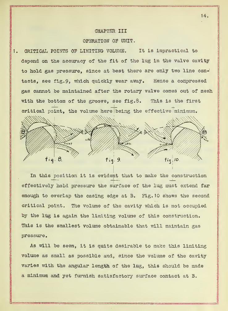
CRITICAL POINTS OP LIMITING- VOLUME. It is impractical to
depend on the accuracy of the fit of the lug in the valve cavity
to hold gas pressure, since at best there are only two line con-
tacts, see fig. 9, which quickly wear away. Hence a compressed
gas cannot be maintained after the rotary valve comes out of mesh
with the bottom of the groove, see fig. 3. This is the first
critical point, the volume here being the effective minimum.
In this position it is evident that to make the construction
effectively hold pressure the surface of the lug must extend far
enough to overlap the casing edge at B. Fig. 10 shows the second
critical point. The volume of the cavity which is not occupied
by the lug is again the limiting volume of this construction.
This is the smallest volume obtainable that will maintain gas
pressure.
As will be seen, it is quite desirable to make this limiting
volume as small as possible and, since the volume of the cavity
varies with the angular length of the lug, this should be made
a minimum and yet furnish satisfactory surface contact at B.
15.
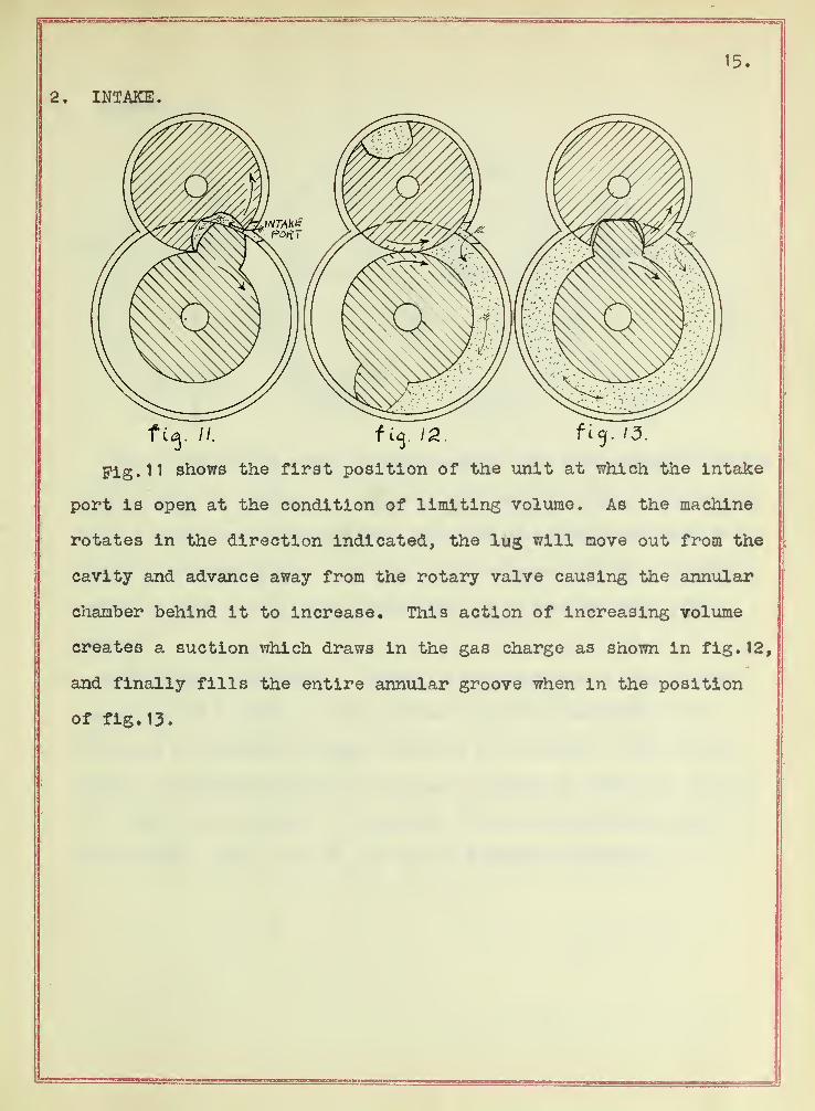
2. INTAKE.
fig. //. f uj. 12. ft 13.
Fig. 11 shows the first position of the unit at which the intake
port is open at the condition of limiting volume. As the machine
rotates in the direction indicated, the lug will move out from the
cavity and advance away from the rotary valve causing the annular
chamber behind it to increase. This action of increasing volume
creates a suction which draws in the gas charge as shown in fig. 12,
and finally fills the entire annular groove when in the position
of fig. 13.


16.
3. COMPRESSION.
Pig, 14 shows the start of compression, the whole annular groove
filled with the charge. In fig. 15 the charge is half compressed.
Pig. 16 shows the discharge port open and the charge compressed to
about four atmospheres. In fig. 17 the compression is a maximum
at the moment of limiting volume and the discharge port just
closed.
4. EXHAUST AND EXPANSION. Exhaust and expansion, being reverse
processes of intake and compression, can be accomplished by a
reversal of function without reversal of rotation. The intake
series of drawings taken in backward succession, figs. 13, 12 and
11, show this reversal of function, illustrating exhaust, and in
like manner, figs. 17, 16, 15 and 14 describe expansion.

17.
CHAPTER IV
COMBINATION OP UNITS.
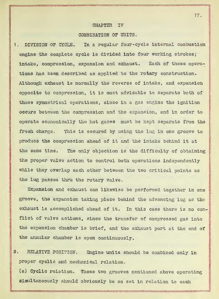
1 . DIVISION OP CYCLE. In a regular four-cycle internal combustion
engine the complete cycle is divided into four working strokes;
intake, compression, expansion and exhaust. Each of these opera-
tions has been described as applied to the rotary construction.
Although exhaust is normally the reverse of intake, and expansion
opposite to compression, it is most advisable to separate both of
those symmetrical operations, since in a gas engine the ignition
occurs between the compression and the expansion, and in order to
operate economically the hot gases must be kept separate from the
fresh charge. This is secured by using the lug in one groove to
produce the compression ahead of it and the intake behind it at
the same time. The only objection is the difficulty of obtaining
the proper valve action to control both operations independently
while they overlap each other between the two critical points as
the lug passes thru the rotary valve.
Expansion and exhaust can likewise be performed together in one
groove, the expansion taking place behind the advancing lug as the
exhaust is accomplished ahead of it. In this case there is no con-
flict of valve actions, since the transfer of compressed gas into
the expansion chamber is brief, and the exhaust port at the end of
the annular chamber is open continuously.
2. RELATIVE POSITION. Engine units should be combined only in
proper cyclic and mechanical relation.
(a) Cyclic relation. These two grooves mentioned above operating
simultaneously should obviously be so set in relation to each


18.
other that, as the compressed charge is being delivered by the
compression chamber, the expansion chamber in the adjacent groove
is receiving a compressed charge at the same time. This arrange-
ment permits a direct transfer of the charge from compression to
expansion chambers, and does away with a pressure- chest into
which the compressed gas would otherwise have to be delivered at
one time and withdrawn at another.
(b) Mechanical Relations. One other consideration is of impor-
tance in connection with relative position, namely the question of
gearing. It has been shown that gear teeth can be cut on the
rotary valve and in the bottom of the groove to minimize the
leakage at the point of rolling contact. But evidently this
gearing is discontinuous between the two positions of limiting
volume, and for smooth operation other gearing must be provided
to at least fill that gap.
If two units are to be operated simultaneously one can be
offset with respect to the other so that if both units are mounted
on the shafts, one groove can be in mesh while the other is out,
and thus maintain rotation. This varies very conveniently with
the cycle relation since the transfer of the compressed gas can-
not last beyond the position of limiting volume, or meshing, in
the compression chamber, and it cannot begin before the point of
limiting volume in the expansion chamber. Time must be allowed
for transfer, hence these critical points of meshing necessarily
overlap, so, in one or the other groove the rotary valves are
constantly geared with the rotor.
. COMPOUNDING. A further combination of units can be effected

19.
if It is desired to obtain compound expansion. Another unit may
be added so that either the exhaust gases from the original ex-
pansion chamber can be further expanded in the new groove or, as
arranged in this gas engine, the rate of expansion can be increased
after rotating 180°. The latter arrangement consists of a port
which opens after 18c° rotation of the original expansion chamber,
allowing the gas to be admitted also in the auxiliary groove at
its limiting position, then the expansion will take place for the
remaining 150° in two grooves instead of in one.
This uses only half of the auxiliary unit and hence it can be
made double; that is, a complete unit in 180° instead of 360°,
by adding diametrically another rotary valve and lug. With this
construction the compound expansion can take place behind both
of the lugs in the new groove and produce the effect of triple
expansion. However, this compound expansion lasts only 150°
since at that time the exhaust port in the original expansion
chamber opens and, all the expansion chambers being connected, any
remaining pressure is lost at this instant. In this way the
extra double unit is in use only half the time.
By adding another primary expansion chamber at 180° to the
first, the compound expansion of the new unit will fit exactly
into the unused part of the compound chamber, then all three
expansion chambers will be in full operation continuously.
CHAPTER V
COMPLETED GAS ENGINE
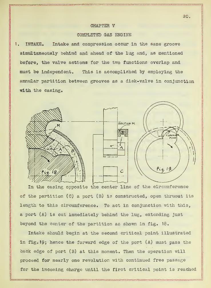
1 . INTAKE. Intake and compression occur in the same groove
simultaneously behind and ahead of the lug and, as mentioned
before, the valve actions for the two functions overlap and
must be independent. This is accomplished by employing the
annular partition between grooves as a disk-valve in conjunction
with the casing.
In the casing opposite the center line of the circumference
of the partition (C) a port (B) is constructed, open thruout its
length to this circumference. To act in conjunction with this,
a port (A) is cut immediately behind the lug, extending just
beyond the center of the partition as shown in fig. 18.
Intake should begin at the second critical point illustrated
in fig. 19; hence the forward edge of the port (A) must pass the
back edge of port (B) at this moment. Then the operation will
proceed for nearly one revolution with continued free passage
for the incoming charge until the first critical point is reached


21.
as the lug again enters the valve cavity. Connecting the intake
manifold at the forward end of this intake port, the path of the
incoming gases will decrease in length, contrary to reciprocating
engine practice. With this arrangement the intake will close with
nearly atmospheric pressure on account of decreased throttling.
2. COMPRESSION. Compression begins also as soon as the second
critical point is passed as shown in fig. 20. Then compression
will progress as discussed in Chap-
ter III to the first point of limit-
ing volume. At this position the
transfer valve is closed and as the
comer of the valve comes out of mesh,
fig. 19, the compressed gas in the
limiting volume expands ahead into the
now closed intake chamber. This expan-
sion raises the pressure of the new
charge so that the following compres-
sion finishes with a greater pressure
and the quantity passing thru the
transfer port is increased slightly. But also the gas in the lim-
iting volume is at a higher pressure and raises the starting pres-
sure even more than before. This cumulative process will con-
tinue until the quantity of gas leaving at high pressure is equal
to the quantity sucked into the intake chamber at low pressure.
3. TRANSFER OP COMPRESSED CHARGE. The transfer of the compressed
charge to the expansion chamber in an adjacent groove should be
f La. 20

22.
accomplished with increasing pressure in order to obtain maximum
pressure at the time of ignition. It has been shown that the
transfer valve cannot be open from the compression chamber after
reaching the first critical point. Similarly the transfer cannot
begin before the second critical point in the expansion groove.
But at this opening position the limiting volume contains so
little gas that any incoming compressed charge will lose some of
its pressure. While the two chambers are in communication the
rate of change of volume of one will balance that of the other
and the first drop in pressure will not be regained. If the
compression groove had a greater width than the expansion groove,
then during the transfer more gas would be discharged from the
compression chamber than taken into the expansion chamber, and
the pressure would rise as the transfer proceeded. By extending
the angular duration of the transfer, the pressure Just previous
to expansion into the limiting volume of the expansion chamber is
kept below that obtained at the end of the transfer. The maximum
pressure would then occur just previous to ignition.
Another advantage of extending the transfer is the reduction
of the percentage of compressed charge lost in the limiting volume
of the compression chamber. The expansion of the remaining gas
into the closed intake chamber is an irreversible process and
hence inefficient.
The construction of a larger compression and intake chamber
would make the engine unsymmetrical so, instead, a double unit is
used, the compression and intake of both sides acting in parallel.
This delivers its double charge every 180°, which is timed cor-
23.
rectly for two expansions per revolution.
4. EXPANSION. The expansion operation is described in chapter III
part 4. This operation can be used for either simple or compound
expansion.
(a) Single Expansion. These two charges delivered per revolution
imply two primary expansions which occur alternately in separate
grooves. These two units are adjacent, the partition between the
grooves can be constructed to act as a rotary disk-valve admitting
the charge first to one groove and then to the other. This
necessitates piping the compressed charge to a port in the casing
opposite the periphery of the common annular wall. Like (A) in
arefig. 18, two ports A cut on opposite sides, each port from the center
of the partition to the back of a lug. A spark plug is placed in
its casing a little beyond the transfer port so that as the rotor
rotates, the port from one lug will first open to the compression
transfer port and immediately thereafter to the spark. This per-
mits ignition at maximum pressure Just as the transfer port is
closed, and furthermore pockets the spark plug so that it could
be replaced by a hot-wire and the ignition occur only at the pro-
per time. After ignition, expansion takes place as described in
chapter III part 4.
(b) Compound Expansion. Compound expansion can be arranged as
discussed in chapter IV part 3« With uniform sized grooves this
compounding will permit a larger expansion than compression,
which is desirable partly for increased efficiency but mostly
for the balancing and gearing of the complete gas engine. The
double unit intake at one end, and the double unit auxiliary at
the other can be set in 90° relation for perfect balancing and


24.
continuous gearing of both sets of rotary valves. The cycle rela-
tion with the primary expansion units fortunately is not disturbed.
Likewise the two single unit expansion grooves in the center bal-
ance each other and maintain continuous meshing being 180° apart*
The disk-valve action for the compounding can also be arranged
conveniently. The ports from the primary expansion grooves are on
their outside partitions, and the ports into the auxiliary groove
are on the last wall. This utilizes every partition for valve
action.
5. EXHAUST. In the paralleling arrangement of compound chambers
it is evident that the exhaust from all must be simultaneous as
the exhaust of one would destroy the pressure of all the others
due to their interconnection. The exhaust port in the casing is
tapped directly over the groove as near the rotary valve as possi-
ble. Then the expansion is effective until the lug's rear edge
uncovers the exhaust port as it enters the valve cavity. During
the next revolution all the burnt gases remaining are now forced
out of the port ahead of the lug.
6. SIMULTANEOUS ACTIONS. As heretofore described, one charge
passes thru the engine in three revolutions, but a new charge is
taken in twice per revolution, therefore six operations are occur-
ing simultaneously. In the first groove intake proceeds behind
and compression ahead of the lug at the same time. In the second
groove at that instant, primary expansion is in operation behind
and exhaust ahead of its lug. In the third and fourth grooves
compound expansion occurs behind and exhaust in front of their
respective lugs.


26.
CHAPTER VI.
PRACTICAL CONSIDERATIONS.
1. MECHANICAL FIT. As in all positive acting engines a mechanical
fit is required. This necessitates good machine work and careful
alignment. The fit need not be tighter than in an ordinary recip-
rocating engine. Equivalent piston rings and oil can be used in
this rotary machine in nearly the same manner as in other engines*
But unlike any piston and cylinder requirements, the rotary valve
must fit both casing and rotor groove. Hence a slight axial motion
of the rotor will tend to move the rotary valve also. Such motion
of the valve is impossible, but the tendency would produce consid-
erable wear.
Lubrication of the surfaces must be accomplished either by
introducing oil with the gasoline or by some system of forced feed.'
The former is simple, but cannot be used if pressures and tempera-
tures run very high, as the oil would burn with the gasoline.
The latter system would be affected by centrifugal force, hence
to lubricate the sides of the groove the oil must be introduced
either at the bottom of the groove or from the sides of the rotary
valve. If the oil is thrown toward the periphery of the valve it
will be carried to the bottom of the groove, and all the surfaces
oiled properly.
The rotor is rigidly supported in bearings, therefore the only
casing wear is due to the piston rings which, however, from their
position are constantly supplied with oil.
2. COMPRESSION. Production and maintenance of compression is
dependent on motion and fit.

27.
(a) Compression. Since the meshing of gear teeth in the bottom
of the groove is depended upon to choice the escape of compressed
gas, it is evident that a high speed of rotation will minimize
the loss of compression in this manner. Furthermore, at the time
the remaining compressed charge escapes ahead into the closed
intake chamber, the rotary valve at the other end of this chamber
has not yet reached its second critical point. Except for the
line contacts with the other lug, the gas would circulate thru,
and instead of compression there would be merely displacement.
This is minimized also by a high rotational speed, hence it is
evident that since rapid rotation causes so slight a loss of
intake pressure it is advantageous to run at high speed.
(b) Maintenance. The disk-valve action as procured in this
machine is scarcely tight enough to hold compression for a
reasonable time. Accordingly the scheme of cumulative compres-
sion does not work out satisfactorily in practice. This can be
remedied by using special valve mechanisms instead of employing
the annular partitions. It is to noted, however, that the method
described herein is the simplest arrangement, and further develop-
ment may revert to this system.
3. OPERATION. For preliminary tests it will be found best to
operate without compounding.
(a) Without Compound Unit. This can be accomplished by closing
the 180° ports of the primary expansion chambers. Then the intake
will equal the expansion and even with intermittent explosions
there will always be a unidirectional motion of the gases thru the
exhaust port.
28.
For actual operation a standard carburetor is piped to the
intake ports, water is circulated thru the cooling system to
prevent warping and a continuous succession of sparks or a hot
wire is used at the spark plug cavity. As the machine rotates
the compression builds up and explosions occur. After minor
adjustments have been made and the machine operates satisfactorily
the exhaust will be at considerable temperature and pressure,
(b) With Complete Engine. Now the compound unit can be piped
in to utilize this energy ordinarily thrown away at the exhaust,
and the complete rotary internal combustion engine will be in
full continuous operation, every chamber being filled with gas
in some stage of the regular four-cycle reciprocating engine.
Every space is continuously utilized and every part in true
rotary motion, insuring high output rating with minimum outlay.
m
-j