The Design Module User’s Guide - COMSOL Multiphysics
140
Design Module User’s Guide
Transcript of The Design Module User’s Guide - COMSOL Multiphysics

Design ModuleUser’s Guide

C o n t a c t I n f o r m a t i o n
Visit the Contact COMSOL page at www.comsol.com/contact to submit general inquiries, contact Technical Support, or search for an address and phone number. You can also visit the Worldwide Sales Offices page at www.comsol.com/contact/offices for address and contact information.
If you need to contact Support, an online request form is located at the COMSOL Access page at www.comsol.com/support/case. Other useful links include:
• Support Center: www.comsol.com/support
• Product Download: www.comsol.com/product-download
• Product Updates: www.comsol.com/support/updates
• COMSOL Blog: www.comsol.com/blogs
• Discussion Forum: www.comsol.com/community
• Events: www.comsol.com/events
• COMSOL Video Gallery: www.comsol.com/video
• Support Knowledge Base: www.comsol.com/support/knowledgebase
Part No. CM024001
D e s i g n M o d u l e U s e r ’ s G u i d e© 2005–2019 COMSOL
Protected by patents listed on www.comsol.com/patents, and U.S. Patents 7,519,518; 7,596,474; 7,623,991; 8,457,932; 8,954,302; 9,098,106; 9,146,652; 9,323,503; 9,372,673; 9,454,625; and 10,019,544. Patents pending.
This Documentation and the Programs described herein are furnished under the COMSOL Software License Agreement (www.comsol.com/comsol-license-agreement) and may be used or copied only under the terms of the license agreement. Portions of this software are owned by Siemens Product Lifecycle Management Software Inc. © 1986–2019. All Rights Reserved. Portions of this software are owned by Spatial Corp. © 1989–2019. All Rights Reserved.
COMSOL, the COMSOL logo, COMSOL Multiphysics, COMSOL Desktop, COMSOL Compiler, COMSOL Server, and LiveLink are either registered trademarks or trademarks of COMSOL AB. ACIS and SAT are registered trademarks of Spatial Corporation. CATIA is a registered trademark of Dassault Systèmes or its subsidiaries in the US and/or other countries. Parasolid is a trademark or registered trademark of Siemens Product Lifecycle Management Software Inc. or its subsidiaries in the United States and in other countries. All other trademarks are the property of their respective owners, and COMSOL AB and its subsidiaries and products are not affiliated with, endorsed by, sponsored by, or supported by those or the above non-COMSOL trademark owners. For a list of such trademark owners, see www.comsol.com/trademarks.
Version: COMSOL 5.5

C o n t e n t s
C h a p t e r 1 : I n t r o d u c t i o n
About the Design Module 8
Overview of the Included Geometry Tools and Features . . . . . . . . 8
Overview of the User’s Guide . . . . . . . . . . . . . . . . . . 11
Where Do I Access the Documentation and Application Libraries? . . . . 11
C h a p t e r 2 : G e o m e t r y T o o l s a n d F e a t u r e s
Constraint and Dimension Features 16
Working with Constraints and Dimensions . . . . . . . . . . . . . 16
Angle . . . . . . . . . . . . . . . . . . . . . . . . . . . 23
Coincident . . . . . . . . . . . . . . . . . . . . . . . . . 23
Concentric . . . . . . . . . . . . . . . . . . . . . . . . . 24
Directed Distance . . . . . . . . . . . . . . . . . . . . . . 24
Distance . . . . . . . . . . . . . . . . . . . . . . . . . . 26
Equal Distance . . . . . . . . . . . . . . . . . . . . . . . . 26
Equal Radius . . . . . . . . . . . . . . . . . . . . . . . . 27
Parallel. . . . . . . . . . . . . . . . . . . . . . . . . . . 27
Perpendicular . . . . . . . . . . . . . . . . . . . . . . . . 28
Position . . . . . . . . . . . . . . . . . . . . . . . . . . 28
Radius . . . . . . . . . . . . . . . . . . . . . . . . . . . 28
Tangent Constraint . . . . . . . . . . . . . . . . . . . . . . 29
Total Edge Length . . . . . . . . . . . . . . . . . . . . . . 30
x-Distance . . . . . . . . . . . . . . . . . . . . . . . . . 30
y-Distance . . . . . . . . . . . . . . . . . . . . . . . . . 31
Geometry Representation 32
Working with the CAD Kernel . . . . . . . . . . . . . . . . . 32
Converting Objects to COMSOL Kernel Representation . . . . . . . 33
Converting Objects to CAD Kernel Representation . . . . . . . . . 34
C O N T E N T S | 3

4 | C O N T E N T S
Importing and Exporting CAD Files 36
Importing 3D CAD Files . . . . . . . . . . . . . . . . . . . . 36
Exporting Objects to 3D CAD Formats . . . . . . . . . . . . . . 41
Using the Defeaturing Tools 43
Finding and Deleting Small Details . . . . . . . . . . . . . . . . 43
Delete Faces . . . . . . . . . . . . . . . . . . . . . . . . 44
Detach Faces . . . . . . . . . . . . . . . . . . . . . . . . 44
Geometry Features 45
Cap Faces . . . . . . . . . . . . . . . . . . . . . . . . . 45
Chamfer . . . . . . . . . . . . . . . . . . . . . . . . . . 46
Delete Faces . . . . . . . . . . . . . . . . . . . . . . . . 47
Delete Fillets . . . . . . . . . . . . . . . . . . . . . . . . 48
Delete Holes . . . . . . . . . . . . . . . . . . . . . . . . 50
Delete Short Edges . . . . . . . . . . . . . . . . . . . . . . 51
Delete Sliver Faces . . . . . . . . . . . . . . . . . . . . . . 52
Delete Small Faces . . . . . . . . . . . . . . . . . . . . . . 53
Delete Spikes . . . . . . . . . . . . . . . . . . . . . . . . 54
Detach Faces . . . . . . . . . . . . . . . . . . . . . . . . 56
Fillet . . . . . . . . . . . . . . . . . . . . . . . . . . . 57
Knit to Solid . . . . . . . . . . . . . . . . . . . . . . . . 59
Loft . . . . . . . . . . . . . . . . . . . . . . . . . . . . 60
Midsurface . . . . . . . . . . . . . . . . . . . . . . . . . 64
Repair . . . . . . . . . . . . . . . . . . . . . . . . . . . 66
Thicken . . . . . . . . . . . . . . . . . . . . . . . . . . 67
C h a p t e r 3 : P r o g r a m m i n g a n d C o m m a n d R e f e r e n c e
Defeaturing Tools 70
Defeaturing Tools — Finding and Deleting Small Details . . . . . . . . 70
Defeaturing Tools — Delete Faces . . . . . . . . . . . . . . . . 73
Defeaturing Tools — Detach Faces . . . . . . . . . . . . . . . . 74

Summary of Commands 75
Commands Grouped by Function 76
Commands in Alphabetical Order 79
Angle . . . . . . . . . . . . . . . . . . . . . . . . . . . 79
Array . . . . . . . . . . . . . . . . . . . . . . . . . . . 80
BezierPolygon . . . . . . . . . . . . . . . . . . . . . . . . 80
CapFaces . . . . . . . . . . . . . . . . . . . . . . . . . . 80
Chamfer . . . . . . . . . . . . . . . . . . . . . . . . . . 81
Chamfer3D . . . . . . . . . . . . . . . . . . . . . . . . . 81
Circle . . . . . . . . . . . . . . . . . . . . . . . . . . . 83
CircularArc . . . . . . . . . . . . . . . . . . . . . . . . . 84
Coincident . . . . . . . . . . . . . . . . . . . . . . . . . 84
Concentric . . . . . . . . . . . . . . . . . . . . . . . . . 85
ConvertToCOMSOL . . . . . . . . . . . . . . . . . . . . . 86
Copy . . . . . . . . . . . . . . . . . . . . . . . . . . . 87
CubicBezier . . . . . . . . . . . . . . . . . . . . . . . . . 87
DeleteFaces . . . . . . . . . . . . . . . . . . . . . . . . . 88
DeleteFillets . . . . . . . . . . . . . . . . . . . . . . . . 90
DeleteHoles . . . . . . . . . . . . . . . . . . . . . . . . 92
DeleteShortEdges . . . . . . . . . . . . . . . . . . . . . . 94
DeleteSliverFaces. . . . . . . . . . . . . . . . . . . . . . . 97
DeleteSmallFaces . . . . . . . . . . . . . . . . . . . . . . . 99
DeleteSpikes . . . . . . . . . . . . . . . . . . . . . . . 102
DetachFaces . . . . . . . . . . . . . . . . . . . . . . . 104
DirectedDistance. . . . . . . . . . . . . . . . . . . . . . 106
Distance . . . . . . . . . . . . . . . . . . . . . . . . . 107
Ellipse . . . . . . . . . . . . . . . . . . . . . . . . . . 108
EqualDistance . . . . . . . . . . . . . . . . . . . . . . . 109
EqualRadius . . . . . . . . . . . . . . . . . . . . . . . . 110
Export, ExportFinal . . . . . . . . . . . . . . . . . . . . . 111
Fillet . . . . . . . . . . . . . . . . . . . . . . . . . . 113
Fillet3D . . . . . . . . . . . . . . . . . . . . . . . . . 113
Import . . . . . . . . . . . . . . . . . . . . . . . . . . 115
InterpolationCurve . . . . . . . . . . . . . . . . . . . . . 121
Knit . . . . . . . . . . . . . . . . . . . . . . . . . . . 122
LineSegment . . . . . . . . . . . . . . . . . . . . . . . 123
C O N T E N T S | 5

6 | C O N T E N T S
Loft . . . . . . . . . . . . . . . . . . . . . . . . . . . 124
Midsurface . . . . . . . . . . . . . . . . . . . . . . . . 126
Mirror . . . . . . . . . . . . . . . . . . . . . . . . . . 127
Move . . . . . . . . . . . . . . . . . . . . . . . . . . 128
Parallel. . . . . . . . . . . . . . . . . . . . . . . . . . 128
Perpendicular . . . . . . . . . . . . . . . . . . . . . . . 128
Point . . . . . . . . . . . . . . . . . . . . . . . . . . 129
Polygon . . . . . . . . . . . . . . . . . . . . . . . . . 129
Position . . . . . . . . . . . . . . . . . . . . . . . . . 130
QuadraticBezier . . . . . . . . . . . . . . . . . . . . . . 130
Radius . . . . . . . . . . . . . . . . . . . . . . . . . . 130
Rectangle . . . . . . . . . . . . . . . . . . . . . . . . . 131
Repair . . . . . . . . . . . . . . . . . . . . . . . . . . 131
Rotate . . . . . . . . . . . . . . . . . . . . . . . . . . 134
Scale . . . . . . . . . . . . . . . . . . . . . . . . . . 134
Square . . . . . . . . . . . . . . . . . . . . . . . . . . 134
TangentConstraint . . . . . . . . . . . . . . . . . . . . . 135
Thicken . . . . . . . . . . . . . . . . . . . . . . . . . 136
TotalEdgeLength . . . . . . . . . . . . . . . . . . . . . . 138
XDistance . . . . . . . . . . . . . . . . . . . . . . . . 138
YDistance . . . . . . . . . . . . . . . . . . . . . . . . 139

1
I n t r o d u c t i o n
Welcome to the Design Module User’s Guide! This guide details the functionality of this optional package that extends the COMSOL Multiphysics® modeling environment with additional tools and features to create and modify geometry, and to import and export geometry using the most common 3D CAD file formats.
This introductory chapter contains an overview of the capabilities of the module, including a summary of the included geometry features, an overview of this guide, and a description of where to find documentation and model examples.
7

8 | C H A P T E R
Abou t t h e De s i g n Modu l e
Overview of the Included Geometry Tools and Features
The Design Module extends the geometry modeling capabilities of COMSOL Multiphysics with constraint and dimension features in 2D, a dedicated geometric kernel, the CAD kernel, features for creating and modifying geometry, import and export of several 3D CAD formats, and functionality to repair and defeature imported geometry objects. Included geometry features are, for example, the fillet and chamfer features in 3D, and the loft feature that can generate 3D surfaces based on cross sectional profiles, which could come from an MRI scan, or could be the faces of existing geometry objects. Further functionality such as the midsurface and thicken allows for converting a thin solid object into a surface, or the other way around.
The import capabilities cover the most common 3D CAD file formats: ACIS®, AutoCAD®, IGES, Inventor®, NX®, Parasolid®, PTC® Creo® Parametric™, PTC® Pro/ENGINEER®, SOLIDWORKS®, and STEP. In addition, support for CATIA® V5 is available as a separate add-on. To exchange data with CAD packages, you can export your geometry to the ACIS®, IGES, Parasolid®, and STEP file formats.
Finally, the product provides a wide range of tools for you to prepare an imported 3D design for meshing and analysis. You can interactively search for and remove geometric features, for example, fillets, holes, slivers, small faces, and short edges. You can also modify objects by detaching a portion to form an additional computational domain, or by creating a fluid domain for computation, in case the CAD design only includes the solid parts.
GEOMETRY FEATURE ICON DESCRIPTION
2D Geometry Features
Angle Constrain the angle between two edges
Coincident Constrain two geometric entities to coincide with each other
Concentric Constrain circular edges and vertices to have the same center
1 : I N T R O D U C T I O N

Directed Distance Constrain the distance between two geometric entities in a given direction
Distance Constrain the distance between two geometric entities
Equal Distance Constrain the distances between two pairs of geometric entities to be equal
Equal Radius Constrain two circular edges to have the same radius
Parallel Constrain straight edges to be parallel
Perpendicular Constrain two straight edges to be perpendicular
Position Constrain the x- and y-coordinates of a point
Radius Constrain the radius of a circular edge
Tangent Constraint Constrain two edges to be tangent
Total Edge Length Constrain the total length for a set of edges
x-Distance Constrain the distance in the x-direction between entities
y-Distance Constrain the distance in the y-direction between entities
3D Geometry Features
Cap Faces Generate faces from edges to fill gaps and create solid objects, or to partition solids
Chamfer Create a bevel on selected edges
Convert to COMSOL Convert to the COMSOL kernel representation
Delete Faces Delete and replace faces
Delete Fillets Find and delete fillets
Delete Holes Find and delete holes
Delete Short Edges Find and delete short edges
Delete Sliver Faces Find and delete sliver faces
GEOMETRY FEATURE ICON DESCRIPTION
A B O U T T H E D E S I G N M O D U L E | 9

10 | C H A P T E R
Delete Small Faces Find and delete small faces
Delete Spikes Find and delete spikes from faces
Detach Faces Detach faces and form a new object from them
Export Export geometry objects to 3D CAD file formats
Fillet Create rounds on selected edges
Import Import geometry objects from 3D CAD file formats
Knit to Solid Knit surface objects to form solid or surface object
Loft Create a lofted surface from a set of profile curves
Midsurface Generate midsurfaces for selected solid objects
Repair Repair and removal of small details
Thicken Create a solid by offsetting selected surfaces
GEOMETRY FEATURE ICON DESCRIPTION
1 : I N T R O D U C T I O N

Overview of the User’s Guide
This documentation covers the Design Module and the add-on for file import of CATIA® V5 files. Instructions on how to use the geometry modeling tools in COMSOL Multiphysics® in general are included with the COMSOL Multiphysics Reference Manual. To help you get started with modeling this module is also accompanied by the quick-start guide Introduction to Design Module.
Where Do I Access the Documentation and Application Libraries?
A number of internet resources have more information about COMSOL, including licensing and technical information. The electronic documentation, topic-based (or context-based) help, and the application libraries are all accessed through the COMSOL Desktop.
T H E D O C U M E N T A T I O N A N D O N L I N E H E L P
The COMSOL Multiphysics Reference Manual describes all core physics interfaces and functionality included with the COMSOL Multiphysics license. This book also has instructions about how to use COMSOL Multiphysics and how to access the electronic Documentation and Help content.
Opening Topic-Based HelpThe Help window is useful as it is connected to many of the features on the GUI. To learn more about a node in the Model Builder, or a window on the Desktop, click to highlight a node or window, then press F1 to open the Help window, which then
If you are reading the documentation as a PDF file on your computer, the blue links do not work to open an application or content referenced in a different guide. However, if you are using the Help system in COMSOL Multiphysics, these links work to other modules (as long as you have a license), application examples, and documentation sets.
A B O U T T H E D E S I G N M O D U L E | 11

12 | C H A P T E R
displays information about that feature (or click a node in the Model Builder followed by the Help button ( ). This is called topic-based (or context) help.
Opening the Documentation Window
To open the Help window:
• In the Model Builder, Application Builder, or Physics Builder click a node or window and then press F1.
• On any toolbar (for example, Home, Definitions, or Geometry), hover the mouse over a button (for example, Add Physics or Build All) and then press F1.
• From the File menu, click Help ( ).
• In the upper-right corner of the COMSOL Desktop, click the Help( ) button.
To open the Help window:
• In the Model Builder or Physics Builder click a node or window and then press F1.
• On the main toolbar, click the Help ( ) button.
• From the main menu, select Help>Help.
To open the Documentation window:
• Press Ctrl+F1.
• From the File menu select Help>Documentation ( ).
To open the Documentation window:
• Press Ctrl+F1.
• On the main toolbar, click the Documentation ( ) button.
• From the main menu, select Help>Documentation.
1 : I N T R O D U C T I O N

T H E A P P L I C A T I O N L I B R A R I E S W I N D O W
Each application includes documentation with the theoretical background and step-by-step instructions to create a model application. The applications are available in COMSOL as MPH-files that you can open for further investigation. You can use the step-by-step instructions and the actual applications as a template for your own modeling and applications. In most models, SI units are used to describe the relevant properties, parameters, and dimensions in most examples, but other unit systems are available.
Once the Application Libraries window is opened, you can search by name or browse under a module folder name. Click to view a summary of the application and its properties, including options to open it or a PDF document.
Opening the Application Libraries WindowTo open the Application Libraries window ( ):
C O N T A C T I N G C O M S O L B Y E M A I L
For general product information, contact COMSOL at [email protected].
To receive technical support from COMSOL for the COMSOL products, please contact your local COMSOL representative or send your questions to
The Application Libraries Window in the COMSOL Multiphysics Reference Manual.
• From the Home toolbar, Windows menu, click ( ) Applications
Libraries.
• From the File menu select Application Libraries.
To include the latest versions of model examples, from the File>Help menu, select ( ) Update COMSOL Application Library.
Select Application Libraries from the main File> or Windows> menus.
To include the latest versions of model examples, from the Help menu select ( ) Update COMSOL Application Library.
A B O U T T H E D E S I G N M O D U L E | 13

14 | C H A P T E R
[email protected]. An automatic notification and case number is sent to you by email.
C O M S O L W E B S I T E S
COMSOL website www.comsol.com
Contact COMSOL www.comsol.com/contact
COMSOL Access www.comsol.com/access
Support Center www.comsol.com/support
Product Download www.comsol.com/product-download
Product Updates www.comsol.com/support/updates
COMSOL Blog www.comsol.com/blogs
Discussion Forum www.comsol.com/community
Events www.comsol.com/events
COMSOL Video Gallery www.comsol.com/video
Support Knowledge Base www.comsol.com/support/knowledgebase
1 : I N T R O D U C T I O N

2
G e o m e t r y T o o l s a n d F e a t u r e s
This chapter describes the tools and features available for creating, importing, and modifying geometry with the Design Module.
15

16 | C H A P T E R
Con s t r a i n t and D imen s i o n F e a t u r e s
In this section:
• Working with Constraints and Dimensions
• Angle
• Coincident
• Concentric
• Directed Distance
• Distance
• Equal Distance
• Equal Radius
• Parallel
• Perpendicular
• Position
• Radius
• Tangent Constraint
• Total Edge Length
• x-Distance
• y-Distance
Working with Constraints and Dimensions
With the Design Module you can apply constraints and dimensions to geometry in 2D geometry sequences, including in geometric parts and on work planes in 3D. By using drawing tools you can quickly draw geometry that resembles a desired shape, then, by adding constraints and dimensions, you can obtain the final geometry.
A dimension (or constraining dimension) is a requirement on geometric entities that has a value, for example the distance between vertex 3 and edge 7 should be 5[m]. You may also define a dimension using an expression that may include global parameters, for example A*5[m] that depends on the parameter A. A constraint is a requirement on geometric entities that does not have a value, for example edges 9 and 11 should be perpendicular.
2 : G E O M E T R Y T O O L S A N D F E A T U R E S

When you apply a constraint or dimension feature, the software immediately adjusts the drawing to satisfy the applied feature. It does this by adjusting the values of the input fields of the geometric features that created the objects. The constraints and dimensions are visualized with symbols and arrows in the Graphics window.
E N A B L I N G T H E C O N S T R A I N T S A N D D I M E N S I O N S F U N C T I O N A L I T Y
To enable the use of constraints and dimensions in a 2D geometry or part, or work plane, go to the Settings window for the Geometry or Plane Geometry node and set Use
constraints and dimensions to On. Note that turning this functionality on for a geometry that consists of a very large number of edges and vertices may slow down the sketch visualization, and it is therefor not recommended.
To enable constraints and dimensions by default in new models make sure that the preference check box Geometry>Use constraints and dimensions>In new models is selected.
When you open an existing model, the constraint and dimension features in the model are normally active. To change this behavior clear the preference check box Geometry>Use constraints and dimensions>When opening a model that uses constraints
and dimensions. After this, when you open a model that uses constraints and dimensions you will get a question whether you want to disable the use of constraints and dimensions. If you answer yes, the constraint and dimension features will be loaded, but they will not have any effect.
If you want to avoid that dimension and constraint features modify the input fields of a geometry feature click the Constrain ( ) button (visible only when the use of constraints and dimensions is enabled) to the right of the text field in the Settings window of the feature. This locks the text field (the Constrain button icon changes into
) to accept only values or expressions that are entered directly, so that the text field now becomes a built-in dimension. In some cases this is also indicated in the Graphics window by the built-in dimensions being visualized with arrows.
Constraints and dimensions can be applied to just about any geometry object, for example to the output of features you have added from the Model Builder, and the output of features such as the Union operation. The following features create objects that cannot be modified using constraints or dimensions:
• Polygon where the data source is not Table
• Interpolation Curve where the data source is not Table or Relative tolerance is not 0
• Rectangle, Square, Circle, Ellipse using layers
C O N S T R A I N T A N D D I M E N S I O N F E A T U R E S | 17
18 | C H A P T E R
• Parametric Curve
• Cross Section
• Edit Object
• Import
• Part Instance
• Partition Objects, Partition Domains, and Partition Edges
• Tangent
Note that even when an object cannot be modified by a constraint or dimension feature, its entities can be used as input for such a feature together with entities that can be modified.
When applying a constraint or dimension to a straight or circular edge, the entire line or full circle is usually considered. For example, a dimension that constrains the distance between a vertex and a straight edge really constrains the distance between the vertex and the straight line underlying the edge.
C R E A T I N G C O N S T R A I N T A N D D I M E N S I O N F E A T U R E S
When applying constraint and dimension to a geometry it is recommended to add the constraints before the dimensions. The applied constraints and dimensions appear as feature nodes in the geometry sequence and the corresponding symbols are displayed in the Graphics window. You can create constraint and dimension features by using either the toolbar buttons from the Sketch toolbar, as described below in the sections Creating Constraints and Creating Dimensions, or by using the contextual menu of a Geometry or Plane Geometry node in the Model Builder. By the latter method you first add a constraint or dimension feature to the geometry sequence, then you select the input entities in its Settings window. When assigning the selections in the Settings window, note that the numbering of the vertices and edges in the sketch visualization (see The Sketch Visualization) sometimes differs from the numbering used in the non-sketch visualization. After building the feature the symbol for the constraint will appear the Graphics window.
C R E A T I N G C O N S T R A I N T S
You can add a constraint using the buttons from the Sketch toolbar by one of the following methods:
• Click the Constraint ( ) button on the Sketch toolbar to enter the smart constraint mode. In this mode, you can start with selecting edges and vertices in the Graphics window. When you have selected a sufficient number of entities, a
2 : G E O M E T R Y T O O L S A N D F E A T U R E S

constraint symbol will appear next to the mouse pointer. This symbol indicates a suggested constraint for the selected entities. If you are satisfied with this suggestion, move the symbol to the desired position on the canvas and left-click to place it there. This will also add the constraint feature node to the geometry sequence, and the geometry will be rebuilt so that you see the effect of the constraint. You can drag the symbol afterwards to adjust its position. To select a different type of constraint from the one suggested, click the button of another constraint before placing the symbol. If a sufficient number of entities are selected for this new constraint, the symbol for the constraint will appear immediately at a default position, and the constraint feature node will be added to the geometry sequence. The smart constraint mode remains active after each applied constraint until you click the Constraint button again.
• Click a button (other than Constraint) from the Constraint group of the Sketch toolbar, to select a specific constraint. If you have already selected a sufficient number of entities before clicking the button for the constraint, the symbol for the constraint will appear immediately at a default position, and the constraint feature node will be added to the geometry sequence. Otherwise, when you have selected a sufficient number of entities, the constraint symbol will appear under the pointer. Move the symbol to the desired position on the canvas and click to place it there. The feature node for the constraint will be added to the geometry sequence, and the geometry will be rebuilt.
C R E A T I N G D I M E N S I O N S
You can add a dimension using the buttons from the Sketch toolbar by one of the following methods:
• Click the Dimension ( ) button on the Sketch toolbar to enter the smart dimension mode. In this mode, you can start with selecting edges and vertices in the Graphics window. When you have selected a sufficient number of entities, a dimension symbol will appear next to the mouse pointer. This symbol indicates a suggested dimension for the selected entities (also considering the mouse pointer position in relation to the selected entities). If you are satisfied with this suggestion, move the symbol to the desired position on the canvas and click to place it there. This will also add the dimension feature node to the geometry sequence. Change the dimension's value in the Settings window for the feature, then click Build
Selected to see its effect. To select a different type of dimension from the one suggested, click the button of another dimension before placing the symbol. If a sufficient number of entities are selected for this new dimension, the symbol for the dimension will appear immediately at a default position, and the dimension feature
C O N S T R A I N T A N D D I M E N S I O N F E A T U R E S | 19

20 | C H A P T E R
node will be added to the geometry sequence. You can drag the symbol afterwards to adjust its position. The smart dimension mode remains active after each applied dimension until you click the Dimension button again.
• Click a button (other than Dimension) from the Dimensions group of the Sketch toolbar, to select a specific dimension. If you have already selected a sufficient number of entities before clicking the button for the dimension, the symbol for the dimension will appear immediately at a default position, and the dimension feature node will be added to the geometry sequence. Otherwise, when you have selected a sufficient number of entities, the dimension symbol will appear under the pointer. Move the symbol to the desired position on the canvas and click to place it there. This will also add the dimension feature node to the geometry sequence. Change the dimension's value in the Settings window for the feature, then click Build
Selected to see its effect.
C O N S T R A I N T A N D D I M E N S I O N S Y M B O L S
In the Graphics window the constraint and dimension features are visualized with symbols, arrows, and dimension values. These are displayed when the sketch visualization (see The Sketch Visualization) is turned on. To turn on sketch visualization click the Sketch ( ) button on the Geometry, Sketch or Work Plane toolbars. You can use the constraint and dimension symbols in the Graphics window in the following ways:
• When you hover over a symbol, it will be highlighted in red, together with the geometric entities it acts upon.
• Use the scroll wheel to cycle through overlapping symbols.
• Drag the symbol to change its position.
• Double-click the symbol to select the corresponding feature node in the geometry sequence, so that its settings are shown in the Settings window. For a dimension, this also gives focus to the dimension value text field.
• Click to select the symbol. Hold down the Ctrl key to select several symbols. Selected symbols are blue and their associated geometric entities are highlighted in turquoise.
• Click the Delete ( ) toolbar button or press the Delete key to delete the selected constraints and dimensions.
S T A T U S O F T H E C O N S T R A I N T S A N D D I M E N S I O N S
Before any constraints or dimensions are applied to a geometry it is possible to grab any of the edges or points of the geometry and move it around in all directions. In this
2 : G E O M E T R Y T O O L S A N D F E A T U R E S

state the geometry is underdefined. All geometric entities are possible to move, and they have an artichoke green color in the Graphics window.
As you add constraints or dimensions to the geometry the software automatically modifies the geometry, and computes the remaining degrees of freedom, i.e. the directions in which it is still possible to move the geometric entities. The edges and vertices that are not possible to move become black in the Graphics window to signify that they are uniquely defined. In this state the geometry is still underdefined.
When a sufficient number constraints and dimensions are added all degrees of freedom become locked, so that none of the vertices or edges can be moved. In this state all geometric entities are black and the geometry is now well defined.
Adding further dimensions to the geometry may cause it to be overdefined. In this state the geometric entities are colored magenta in the Graphics window.
The overall status of the applied constraints and dimensions is also indicated in the Settings window for the Geometry or the Plane Geometry node, at the bottom of the Constraints and Dimensions section. The following status messages can appear there:
TABLE 2-1: CONSTRAINT AND DIMENSION STATUS MESSAGES.
STATUS DESCRIPTION
Underdefined There are too few constraints and dimensions to define the geometry uniquely. Add more constraints and dimensions.
Well defined The constraints and dimensions define the geometry uniquely, and they do not contradict each other. Note that redundant constraints are accepted in a well-defined geometry, but not redundant dimensions.
Overdefined There are too many dimensions. Remove dimensions to get a well defined geometry.
Overdefined and underdefined
There are some conflicting or redundant constraints/dimensions but the geometry is not uniquely defined.
Inconsistent The software was unable to satisfy the constraints and dimensions, but a solution might exist.
Need X more constraints/dimensions
Add X constraints/dimensions to get a well defined geometry.
Y rigid body degrees of freedom
Of the X remaining degrees of freedom, Y degrees of freedom are rigid body motions (translation and rotation of the whole geometry).
X too many constraints/dimensions
Remove X constraints/dimensions to get a well defined geometry.
C O N S T R A I N T A N D D I M E N S I O N F E A T U R E S | 21

22 | C H A P T E R
Note that the status concerns the state of the geometry when it was last built, that is, the geometry you see in the Graphics window.
Each constraint and dimension node in the Model Builder can have an error subnode that tells if the node is overdefined or inconsistent. When this happens, the software tries to satisfy the other constraints and dimensions, ignoring the problematic ones.
B U I L D I N G A S U B S E T O F T H E C O N S T R A I N T A N D D I M E N S I O N F E A T U R E S
To troubleshoot an overdefined or inconsistent state for constraints and dimensions and to find conflicting constraints or dimensions you can disable the corresponding features in the geometry sequence. Select one or several nodes in the Model Builder, then right-click the selected nodes and select Disable. Rebuild the geometry sequence to see the effect.
Another option is to change how the constraint and dimension features are built in the geometry sequence. To do this, in the Settings window for the Geometry or the Plane
Geometry node, in the Constraints and Dimensions section, the Constraint and dimension
features to build list provides the following options:
• All: This option means that all constraint and dimension features in the sequence are applied, also the features that come after the feature which you are building up to. This is the default setting.
• None: Use this option to turn off the build of constraint and dimension features. The corresponding feature nodes are grayed out in the geometry sequence. Note that built-in dimensions defined by the geometric primitive features and other features may still apply.
• Up to build target: With this option selected only the constraint and dimension features up to the feature you are building up to are applied to the geometry.
H E L P P O I N T S
For some constraint and dimension features the Settings window contains a section Help Points where you can specify coordinates for the help points on curved edges. The help points are used as initial guesses when solving the constraint or dimension. More specifically, when there are several solutions to a constraint or dimension, the software chooses the solution that is closest to the help points. When you add a constraint or dimension using a toolbar button, the help points are based on the position of the mouse click for the edge selection. The software updates the help point coordinates when the geometry is built, so that the help points correspond to the found solution.
2 : G E O M E T R Y T O O L S A N D F E A T U R E S

Angle
Use the Angle dimension to specify the angle between two edges. The specified angle is applied between the tangent rays at the point of intersection for the two curves underlying the edges.
Add an Angle dimension as follows:
1 Click the Angle ( ) toolbar button.
2 Select two edges, or a vertex that has exactly two adjacent edges.
3 Move the mouse pointer to select one of the four angular sectors to measure, and to adjust the radial position of the circular arrow symbol.
4 Click to place the symbol.
5 In the Settings window for Angle change the value in the Angle text field.
6 Click Build Selected to rebuild the geometry with the new value.
The Settings window for Angle contains the following sections:
• First Ray: Change the selection for the first edge. The Reverse direction check box determines the direction of the edge's tangent ray at the intersection point.
• Second Ray: Change the selection for the second edge. The Reverse direction check box determines the direction of the edge's tangent ray at the intersection point.
• Dimension Value: Adjust the value of the angle. The angle is measured from the first tangent ray to the second tangent ray in the counterclockwise direction.
• Help Points: Change the help point coordinates for the two edges. These are used as initial guesses when computing a point of intersection (see Help Points).
Coincident
Use the Coincident constraint to constrain two geometric entities to coincide with each other. Depending on the type of entities selected for the constraint the following conditions may apply:
• A vertex coincides with a straight edge if the vertex lies on the line.
• A vertex coincides with a circular edge if the vertex lies on the circle.
• A vertex coincides with a spline edge if the vertex lies on the spline parameterization (but possibly outside the edge's parameter interval).
• Two straight edges coincide if they lie on the same line.
C O N S T R A I N T A N D D I M E N S I O N F E A T U R E S | 23

24 | C H A P T E R
• Two circular edges coincide if they lie on the same circle.
• Two spline edges coincide if they have the same spline parameterization (but possible different parameter intervals).
Add a Coincident constraint as follows:
1 Click the Coincident ( ) toolbar button.
2 Select two vertices or edges, or one vertex and one edge.
3 Move the mouse pointer to position the coincident symbol.
4 Click to place the symbol.
The Settings window for Coincident contains the following sections:
• Geometric Entity Selection: Change the selected entities and their type.
• Help Points: Change the help point coordinates for the selected entities. These are used as initial guesses when making a vertex coincident with a curved edge (see Help Points).
Concentric
Use the Concentric constraint to constrain circular edges to have the same center, or to constrain the center point of circular edges and vertices to coincide.
Add a Concentric constraint as follows:
1 Click the Concentric ( ) toolbar button.
2 Select circular edges and/or vertices.
3 Move the mouse pointer to position the concentric symbol.
4 Click to place the symbol.
The Settings window for Coincident contains the following sections:
• Geometric Entity Selection: Change the selected circular edges and vertices.
Directed Distance
Use the Directed Distance dimension to set the distance in a specified direction between two geometric entities.
The directed distance from, or to, an edge is defined using a stationary point for the directed point-to-point distance along the edge. For example, there are four ways to define the directed distance between two circles.
2 : G E O M E T R Y T O O L S A N D F E A T U R E S

Add a Directed Distance dimension as follows:
1 Click the Directed Distance ( ) toolbar button.
2 Select two vertices or curved edges, or a vertex and a curved edge.
3 Optionally, select a straight edge that specifies the direction in which the distance between the entities is measured.
4 Move the mouse pointer to position the arrow symbol.
5 Click to place the symbol.
6 If you have not chosen a straight edge in Step 3 above, in the Settings window for Directed Distance specify the components of the direction vector in the x and y text fields.
7 If you have chosen a straight edge in Step 3, you can optionally change the Direction for the dimension from Parallel with edge (default) to Perpendicular to edge.
8 Edit the value in the Distance text field. Note that the distance can also be negative or zero.
9 Click Build Selected to see the effect of the new distance value.
The Settings window for Directed Distance contains the following sections:
• Geometric Entity Selection: Select the entities for the dimension.
• Direction: Set the direction in which the distance is measured by selecting one of the options from the Direction list box:
- Vector: Specify the direction by the x and y components of a direction vector. This is the default option.
- Parallel with edge: The direction is parallel with the edge in the Straight edge selection.
- Perpendicular to edge: The direction is perpendicular to the edge in the Straight
edge selection.
• Dimension Value: Enter the distance expression in the Distance text field. The distance may be positive, negative, or zero. The sign does not matter when Direction is set to Perpendicular to edge.
• Help Points: Change the help point coordinates for the selected entities. The help points are used as the initial guess to determine which directed distance to measure (see Help Points).
C O N S T R A I N T A N D D I M E N S I O N F E A T U R E S | 25

26 | C H A P T E R
Distance
Use the Distance dimension to set the distance between two geometric entities. The distance from/to an edge is defined using a stationary point for the point-to-point distance along the edge. For example, there are four ways to define the distance between two circles. When you applied to two straight edges, the distance dimension constrains the edges to be parallel. For singe edge the distance is applied between the endpoints for the edge.
Add a Distance dimension as follows:
1 Click the Distance ( ) toolbar button.
2 Select two vertices or edges, a vertex and an edge, or an edge.
3 Move the mouse pointer to position the arrow symbol.
4 Click to place the symbol.
5 In the Settings window for Distance edit the value in the Distance text field.
6 Click Build Selected to see the effect of the new distance value.
The Settings window for Distance contains the following sections:
• Geometric Entity Selection: Change the selected entities and their type.
• Dimension Value: Enter the distance expression in the Distance text field.
• Help Points: Change the help point coordinates for the selected entities. The help points are used as the initial guess to determine which distance to measure (see Help Points).
Equal Distance
Use the Equal Distance constraint to constrain the distances between two pairs of geometric entities to be equal. The distance from/to an edge is defined using a stationary point for the point-to-point distance along the edge. For example, there are four ways to define the distance between two circles.
The help points (the points where you clicked when selecting the edges) are used to determine which distance to measure.
Add an Equal Distance constraint as follows:
1 Click the Equal Distance ( ) toolbar button.
2 Select two vertices or edges, or a vertex and an edge.
2 : G E O M E T R Y T O O L S A N D F E A T U R E S

3 Move the pointer to position the arrow symbol, then click to place the symbol for the first pair of entities.
4 Again, select two vertices or edges, or a vertex and an edge.
5 Click to place the second arrow symbol.
The same label will be displayed with the arrow symbols to indicate the constraint.
The Settings window for Equal Distance contains the following sections:
• First Distance: Change the selected entities and their type for the first pair.
• Second Distance: Change the selected entities and their type for the second pair.
• Graphics: Edit the label displayed with the arrow symbol for the constraint.
• Help Points: Change the help point coordinates for the selected entities. The help points are used as the initial guess to determine which distance to measure (see Help Points).
Equal Radius
Use the Equal Radius constraint to constrains two circular edges to have the same radius.
Add an Equal Radius constraint as follows:
1 Click the Equal Radius ( ) toolbar button.
2 Select a circular edge.
3 Move the pointer to position the arrow symbol, then click to place the symbol for the first edge.
4 Select another circular edge.
5 Click to position the second arrow symbol.
The same label will be displayed with the arrow symbols to indicate the constraint.
The Settings window contains the following section:
• Edge Selection: Change the selected entities.
• Graphics: Edit the label displayed with the arrow symbol for the constraint.
Parallel
Use the Parallel constraint to constrain straight edges to be parallel.
Add a Parallel constraint as follows:
C O N S T R A I N T A N D D I M E N S I O N F E A T U R E S | 27

28 | C H A P T E R
1 Click the Parallel ( ) toolbar button.
2 Select straight edges.
3 Move the pointer to position the parallel symbol, then click to place it.
The Settings window for Parallel contains the following section:
• Edge Selection: Change the selected entities.
Perpendicular
Use the Perpendicular constraint to constrain two straight edges to be orthogonal.
Add a Perpendicular constraint as follows:
1 Click the Perpendicular ( ) toolbar button.
2 Select two straight edges, or a vertex that has exactly two adjacent edges.
3 Move the pointer to position the perpendicular symbol, then click to place it.
The settings window for Perpendicular contains the following section:
• Edge Selection: Change the selected entities.
Position
Use the Position dimension to specify the coordinates for a vertex.
Add a Position dimension as follows:
1 Click the Position ( ) toolbar button.
2 Select a vertex.
3 Click somewhere on the canvas to place the position symbol.
4 In the Settings window for Position edit the coordinates in the x and y text fields.
5 Click Build Selected to rebuild the geometry with the new coordinates for the vertex.
The Settings window for Position contains the following sections:
• Vertex Selection: Change the selected vertex.
• Coordinates: Edit the coordinate expressions.
Radius
Use the Radius dimension to set the radius for a circular edge.
2 : G E O M E T R Y T O O L S A N D F E A T U R E S

Add a Radius dimension as follows:
1 Click the Radius ( ) toolbar button.
2 Select a circular edge.
3 Click somewhere on the canvas to place the arrow symbol.
4 In the Settings window for Radius edit the value in the Radius text field.
5 Click Build Selected to rebuild the geometry with the new radius.
The Settings window for Radius contains the following sections:
• Edge Selection: Change the selected circular edge.
• Dimension Value: Edit the radius expression.
Tangent Constraint
Use the Tangent Constraint to constrain two edges to have a point of tangency. For each edge, you can optionally specify an adjacent vertex as the point of tangency.
Add a Tangent Constraint as follows:
1 Click the Tangent Constraint ( ) toolbar button.
2 Select two edges (and optionally a vertex adjacent to each edge), or a vertex having exactly two adjacent edges.
3 Click somewhere on the canvas to place the tangent symbol.
The Settings window for Tangent Constraint contains the following sections:
• First Edge: Change the selected edge. To set the point of tangency to a vertex, from the Point of tangency list, choose Vertex, then activate the Vertex selection, and select a vertex adjacent to the edge. With the default setting for Point of tangency, Anywhere, the tangency can be applied anywhere on the edge.
• Second Edge: Change the selected edge and point of tangency similarly as in the First Edge section.
• Help Points: Change the help point coordinates for the selected edges. The help points are used as the initial guess when computing the intersection of the edges if a vertex has not been selected (see Help Points).
C O N S T R A I N T A N D D I M E N S I O N F E A T U R E S | 29

30 | C H A P T E R
Total Edge Length
Use the Total Edge Length dimension specify the total length for a set of edges. The edges must form a chain and all lie on the same line, circle, or spline.
Add a Total Edge Length dimension as follows:
1 Click the Total Edge Length ( ) toolbar button.
2 Select edges that form a chain on the same line, circle, or spline.
3 Click somewhere on the canvas to place the arrow symbol.
4 In the Settings window for Total Edge Length edit the value in the Length text field.
5 Click Build Selected to rebuild the geometry with the new length.
The Settings window for Total Edge Length contains the following section:
• Edge Selection: Change the selected edges.
• Dimension Value: Edit the length expression.
x-Distance
Use the x-Distance dimension to set the distance in the x-direction between two geometric entities. The x-distance from or to an edge is defined using a stationary point for the point-to-point x-distance along the edge. For example, there are four ways to define the x-distance between two circles.
Add an x-Distance dimension as follows:
1 Click the x-Distance ( ) toolbar button.
2 Select two vertices, two curved edges, or a vertex and a curved edge.
3 Click somewhere on the canvas to place the arrow symbol.
4 In the Settings window for x-Distance edit the value in the Distance text field. Note that the distance can also be negative or zero.
5 Click Build Selected to rebuild the geometry with the new distance value.
The Settings window for x-Distance contains the following sections:
• Geometric Entity Selection: Change the selected entities and their type.
2 : G E O M E T R Y T O O L S A N D F E A T U R E S

• Dimension Value: Enter the distance expression in the Distance text field. The distance may be positive, negative, or zero.
• Help Points: Change the help point coordinates for the selected entities. The help points are used as the initial guess to determine which x-distance to measure (see Help Points).
y-Distance
Use the y-Distance dimension to set the distance in the y-direction between two geometric entities. The y-distance from or to an edge is defined using a stationary point for the point-to-point y-distance along the edge. For example, there are four ways to define the y-distance between two circles.
Add an y-Distance dimension as follows:
1 Click the y-Distance ( ) toolbar button.
2 Select two vertices, two curved edges, or a vertex and a curved edge.
3 Click somewhere on the canvas to place the arrow symbol.
4 In the Settings window for y-Distance edit the value in the Distance text field. Note that the distance can also be negative or zero.
5 Click Build Selected to rebuild the geometry with the new distance value.
The Settings window for y-Distance contains the following sections:
• Geometric Entity Selection: Change the selected entities and their type.
• Dimension Value: Enter the distance expression in the Distance text field. The distance may be positive, negative, or zero.
• Help Points: Change the help point coordinates for the selected entities. The help points are used as the initial guess to determine which y-distance to measure (see Help Points).
C O N S T R A I N T A N D D I M E N S I O N F E A T U R E S | 31

32 | C H A P T E R
Geome t r y R ep r e s e n t a t i o n
Working with the CAD Kernel
The component of the COMSOL Multiphysics® software that is used to represent, build, and manage the interactions between geometric objects is the geometric kernel or geometric modeler. There are two kernels used by the software, the COMSOL kernel, and the CAD kernel (the Parasolid® kernel) that is included with the CAD Import Module, the Design Module, and LiveLink™ products interfacing CAD packages.
With a license for the Design Module the software defaults to the CAD kernel for representing the geometry. You need to use the CAD kernel to apply the geometry features included with this module, for example the defeaturing and repair tools, as well as to import 3D geometries using various 3D CAD file formats. Exceptions are the constraint and dimension features that do not require the CAD kernel.
The 3D operations and primitives listed in Table 2-2 do not support the CAD kernel — they always use the COMSOL kernel. However, an automatic conversion is performed for these objects before they are used as input to geometry features that require the CAD kernel, see Converting Objects to CAD Kernel Representation.
C H A N G I N G T H E G E O M E T R I C K E R N E L
To switch between geometric kernels, you can click the Geometry node, then in its Settings window, from the Geometry representation list choose either the CAD kernel or COMSOL kernel.
TABLE 2-2: 3D GEOMETRY FEATURES THAT DO NOT SUPPORT THE PARASOLID GEOMETRY KERNEL
FEATURE NAME FEATURE NAME
Bezier Polygon Point
Eccentric Cone Polygon
Extrude Pyramid
Helix Revolve
Hexahedron Sweep
Interpolation Curve Tetrahedron
Parametric Curve Torus
Parametric Surface Work Plane
2 : G E O M E T R Y T O O L S A N D F E A T U R E S
When you change the Geometry representation setting, all nodes that support the CAD kernel are marked as edited with an asterisk (*) in the upper-right corner of the node’s icon. To rebuild the geometry using the new kernel, click the Build All button ( ). To avoid re-solving an already solved model, you can click the Update Solution button ( ) on the Study toolbar to map the solutions from the geometry represented by the CAD kernel to the new geometry represented by the COMSOL kernel.
When you create a new model, its default geometry representation is controlled by the preference setting Geometry>Geometry representation>In new models.
When you open an existing model, you normally use the geometry representation used in the model. To always get the possibility to convert the geometry to the COMSOL kernel, change the preference setting Geometry>Geometry representation>When
opening an existing model to Convert to COMSOL kernel.
Converting Objects to COMSOL Kernel Representation
To convert CAD objects (geometric objects represented by the CAD kernel) to objects represented by the COMSOL kernel, from the Geometry toolbar, Conversions menu, select Convert to COMSOL ( ).
If you solve a model using the CAD kernel, it is not possible to view and postprocess the solution if you open it in a COMSOL Multiphysics
session where a license for the CAD Import Module, Design Module, or one of the LiveLink for CAD products is not available, unless, before saving the model, you change the geometry representation to COMSOL kernel and update the solution. This is possible to do only for 3D geometry sequences that do not contain geometry features that require the CAD kernel.
The COMSOL geometry file format (.mphbin, or .mphtxt) can contain geometric objects saved in both the CAD kernel and COMSOL kernel representations. To import geometry from such a file to a geometry sequence that uses the COMSOL kernel, you need to convert geometry objects to the COMSOL representation before exporting to the file.
G E O M E T R Y R E P R E S E N T A T I O N | 33

34 | C H A P T E R
C O N V E R T T O C O M S O L
Select the objects that you want to convert in the Graphics window. The selected objects are displayed in the Input objects list.
S E L E C T I O N S O F R E S U L T I N G E N T I T I E S
If you want to make the resulting entities contribute to a cumulative selection, select a cumulative selection from the Contribute to list (the default, None, gives no contribution), or click the New button to create a new cumulative selection (see Cumulative Selections in the COMSOL Multiphysics Reference Manual).
Select the Resulting objects selection check box to create predefined selections (for all levels — objects, domains, boundaries, edges, and points — that are applicable) in subsequent nodes in the geometry sequence. To also make all or one of the types of resulting entities (domains, boundaries, edges, and points) that the resulting objects consist of available as selections in all applicable selection lists (in physics and materials settings, for example), choose an option from the Show in physics list: All levels, Domain
selection, Boundary selection, Edge selection, or Point selection. The default is Domain
selection, which is suitable for use with materials and physics defined in domains. For use with a boundary condition, for example, choose Boundary selection. These selections do not appear as separate selection nodes in the model tree. Select Off to not make any selection available outside of the geometry sequence.
Converting Objects to CAD Kernel Representation
If the current geometry representation for the geometry sequence is CAD kernel, an automatic conversion of COMSOL objects to CAD objects takes place before using the objects in Boolean operations and before using the objects in the Convert to Solid,
Convert to Surface, Convert to Curve, and Convert to Point operations. This ensures that the CAD kernel is used in the above mentioned operations. This conversion is also performed when COMSOL objects are used as input to features that require the CAD kernel, for example the Knit to Solid feature
An automatic conversion to CAD objects is also performed before exporting geometry in the ACIS®, Parasolid®, STEP, and IGES file formats.
If the automatic conversion cannot be performed, the geometry operation is performed by the COMSOL kernel. For example, geometry objects created from a mesh cannot be converted to CAD kernel representation. Other examples of geometry objects that cannot be converted to CAD representation include objects that have an
2 : G E O M E T R Y T O O L S A N D F E A T U R E S

edge adjacent to three or more isolated faces, or objects that have a face bounded by an edge loop that intersects itself.
The automatic conversion to CAD kernel representation is not performed if one of the input objects to the Boolean or conversion operation is the result of a previous Convert
to COMSOL operation.
G E O M E T R Y R E P R E S E N T A T I O N | 35

36 | C H A P T E R
Impo r t i n g and Expo r t i n g CAD F i l e s
Importing 3D CAD Files
To import geometry objects from a 3D CAD file, from the Home or the Geometry toolbar, click Import ( ). In the Import section of the Settings window, select 3D CAD
file from the Geometry import list. You can also skip this step as the type of the selected file is automatically recognized by the code. Click Browse to locate the file to import, or enter the path to the file. Before clicking the Import button consider to review and configure the import settings. If you have changed some settings after importing a file, the file is automatically re-imported when you click a build button.
The imported geometry objects are represented by the CAD kernel, see Working with the CAD Kernel, which is the geometric kernel used by the CAD Import Module, Design Module, and LiveLink™ products interfacing CAD packages.
Some 3D CAD formats use periodic parameterization for edges and faces. For example, a full-revolution cylindrical edge or face appears seamless in the CAD program. During import edges or faces that have a periodic parameterization are cut in two halves by inserting new vertices and edges. This is done because the mesh algorithms do not support periodic entities. You can ignore such inserted edges using an Ignore Edges feature from Virtual Operations.
S U P P O R T E D F O R M A T S
The CAD import supports the following 3D CAD formats:
TABLE 2-3: SUPPORTED 3D CAD FILE FORMATS
FILE FORMAT NOTES FILE EXTENSIONS SUPPORTED VERSIONS
ACIS® 1, .sat, .sab up to 2019 1.0
AutoCAD® 1, 2 .dwg, .dxf 2.5-2019
CATIA® V5 2, 3 .CATPart, .CATProduct
R8 to R2019
PTC® Creo® Parametric™ 1 .prt, .asm 1.0-6.0
IGES 1 .igs, .iges up to 5.3
Inventor® assembly 1, 2 .iam 11, 2008-2019
Inventor® part 1, 2 .ipt 6 to 11, 2008-2019
NX® 1, 4 .prt up to 1847
2 : G E O M E T R Y T O O L S A N D F E A T U R E S

Note 1: This format requires a license for one of the CAD Import Module, or Design Module, or LiveLink product for a CAD package.
Note 2: Available only on a supported Windows operating system.
Note 3: This format requires, in addition to the CAD Import Module, or Design Module, or a LiveLink product for a CAD package, a license for the File Import for CATIA V5 module.
Note 4: Support for the NX® file format is available only on a supported Windows or Linux operating system.
Note 5: Embedded parts in assemblies are not supported. To import such an assembly, first convert the embedded parts to external parts.
A S S O C I A T I V I T Y
When possible the import maintains associativity for the imported geometry objects, so that when the CAD file is re-imported the settings applied to the geometric entities, for example physics or material settings, are retained. To maintain associativity the import relies on information in the CAD file that uniquely identifies the geometry objects and their entities, such as faces, edges, and points. This information is usually included in the CAD file if the geometry is saved in the format of the CAD software where it was created, but not when the geometry is exported to another CAD format. When re-importing a CAD file the import automatically tries to identify and match all geometry objects and their entities to the previous version. This may fail if the topology (structure) of the geometry has changed since the last import.
Parasolid® 1 .x_t, .x_b up to V32.0
PTC® Pro/ENGINEER® 1 .prt, .asm 16 to Wildfire 5
SOLIDWORKS® 1, 2, 5 .sldprt, .sldasm 98-2019
STEP 1 .step, .stp AP203E1, AP214
TABLE 2-3: SUPPORTED 3D CAD FILE FORMATS
FILE FORMAT NOTES FILE EXTENSIONS SUPPORTED VERSIONS
I M P O R T I N G A N D E X P O R T I N G C A D F I L E S | 37

38 | C H A P T E R
Note: To ensure that associativity is maintained when re-importing a CAD file work with CAD files saved in the originating CAD software’s format, and avoid changes to the topology (structure) of the geometry. When an associative import is not possible use coordinate-based selections, such as the Ball, Box, and Cylinder selections in 3D (see Creating Selections From Geometric Primitives and Operations in the COMSOL Multiphysics Reference Manual).
L E N G T H U N I T
In the Length unit list, select From CAD document to change the geometry’s length unit to the unit in the file (if the file has a length unit). Select From COMSOL to keep the geometry’s length unit and scale the objects in the file to the geometry’s unit.
O B J E C T S T O I M P O R T
Select the types of objects to import using the Solids, Surfaces, and Curves and points check boxes.
If the Surfaces check box is selected, you can choose how COMSOL imports the surfaces using the list under For surface objects:
• Choose Form solids (the default) to knit together surface objects to form solids.
• Choose Knit surfaces to form surface objects by knitting.
• Choose Do not knit to not form any surface or solid objects from the imported surfaces.
For the Form Solids and Knit surfaces options select the Fill holes check box to generate new faces to replace missing geometry.
To import wireframe geometry you need to select the Curves and points check box. With this option, the Unite curve objects check box is selected by default to unite the imported curve objects, which speeds up the rendering of the geometry.
I M P O R T O P T I O N S
The Absolute import tolerance is a length measured in the geometry’s unit after the import. When importing 3D CAD files, the program merges geometric entities with a distance smaller that this tolerance.
If you select the Check imported objects for errors check box, a warning appears if the imported objects contain errors.
2 : G E O M E T R Y T O O L S A N D F E A T U R E S

If you select the Repair imported objects check box, the software tries to repair defects and remove details smaller than the Absolute import tolerance.
If you select the Remove redundant edges and vertices check box, the software tries to remove redundant edges and vertices.
S E L E C T I O N S O F R E S U L T I N G E N T I T I E S
If you want to make the resulting entities contribute to a cumulative selection, select a cumulative selection from the Contribute to list (the default, None, gives no contribution), or click the New button to create a new cumulative selection (see Cumulative Selections in the COMSOL Multiphysics Reference Manual).
Select the Resulting objects selection check box to create predefined selections (for all levels — objects, domains, boundaries, edges, and points — that are applicable) in subsequent nodes in the geometry sequence. To also make all or one of the types of resulting entities (domains, boundaries, edges, and points) that the objects consist of available as selections in all applicable selection lists (in physics and materials settings, for example), choose an option from the Show in physics list: All levels, Domain selection, Boundary selection, Edge selection, or Point selection. The default is Domain selection, which is suitable for use with materials and physics defined in domains. For use with a boundary condition, for example, choose Boundary selection. These selections do not appear as separate selection nodes in the model tree. Select Off to not make any selection available outside of the geometry sequence.
Select the Individual objects selections check box to create predefined selections (for all levels — objects, domains, boundaries, edges, and points — that are applicable) in subsequent nodes in the geometry sequence for each individual object in the geometry file and for each relevant entity level. To also make all or one of the types of resulting entities (domains, boundaries, edges, and points) that the objects consist of available as selections in all applicable selection lists (in physics and materials settings, for example), choose an option from the Show in physics list: All levels, Domain selection, Boundary selection, Edge selection, or Point selection. The default is Domain selection, if available, which is suitable for use with materials and physics defined in domains. For use with a boundary condition, for example, choose Boundary selection. These selections do not appear as separate selection nodes in the model tree. Select Off to not make any selection available outside of the geometry sequence.
I M P O R T I N G A N D E X P O R T I N G C A D F I L E S | 39

40 | C H A P T E R
S E L E C T I O N S G E N E R A T E D B A S E D O N I N F O R M A T I O N I N T H E C A D F I L E
The following types of data from the CAD file are used to generate selection on the imported geometry:
• Material assignments can generate objects selections that are named according to the material names in the CAD file.
• Layer assignments of objects and entities, when supported by the CAD format, can generate object, boundary, edge, and point selections that are named according to the layer names in the CAD file.
• Color assignments to objects, faces, or edges can generate object, boundary, and edge selections, respectively.
After the import the generated selections are displayed in the Settings window for the Import node in sections named according to the entity level of the selections:
• Object Selections
• Boundary Selections
• Edge Selections
• Point Selections
Depending on which selections are generated, a subset of the above sections is displayed. The selections are listed in tables with the following columns:
• Name: Here you can edit the selection name that is generated by the import. For colors the generated names are of the type Color 1, Color 2, etc., for materials and layers the names from the CAD file are used.
• Name in file: This column contains the original name of the selection. To display this column select the Show names from file check box above the table.
• Keep: Select the check box in this column to make the selection available in selection lists for subsequent nodes in the geometry sequence.
• Physics: Select the check box in this column to make the selection available in all applicable selection lists (in physics and materials settings, for example).
• Contribute to: If you want to make the objects or entities in the selection contribute to a cumulative selection, select a cumulative selection from the Contribute to list (the default, None, gives no contribution), or click the New Cumulative Selection button under the table to create a new cumulative selection (see Cumulative Selections in the COMSOL Multiphysics Reference Manual).
Click a row in a table to highlight the corresponding selection on the geometry in the Graphics window. To help with identifying the color selections, these are highlighted
2 : G E O M E T R Y T O O L S A N D F E A T U R E S

with the colors defined in the imported CAD file. To always highlight on the geometry the color selections that you keep select from the Graphics toolbar Colors > Show
Selection Colors.
The selections listed in the Object Selections section that are made available for the geometry sequence or physics setup are always available in all input selection lists, including all applicable entity selection lists. For example, the object selection of a solid object, generated for a material from the CAD file, automatically results in domain, boundary, edge, and point selections with the same name, so that you can use it to apply a boundary material, or a boundary condition. In contrast, a color assigned to a face of a solid object in the CAD file results in a boundary selection that is displayed in the Boundary Selections section, and it is available in all applicable boundary selection lists, but not, for example, in any edge selection lists.
Exporting Objects to 3D CAD Formats
With a license for the Design Module you can export 3D geometry objects to the ACIS®, IGES, Parasolid®, and STEP formats. To do this:
• right-click the Geometry node and select Export ( ), or
• on the Geometry toolbar click Export ( ).
Then, in the File type list, select Parasolid binary file, Parasolid text file, ACIS binary file, ACIS text file, IGES file, or STEP file. Use the Browse button to choose the filename, then click Save to close the Export Geometry window.
Next, select Export selected objects to export only chosen geometry objects or select Export entire finalized geometry to export the resulting geometry of a Form Union or Form Assembly operation.
When exporting to an ACIS file format choose the ACIS file format version. Available versions are 4.0, 7.0, 2016 1.0 (default).
For the Parasolid, IGES, and STEP file formats select a Length Unit. A unit conversion is carried out when the selected unit is different from the length unit of the geometry. A unit conversion is not done for the default From geometry option.
Note that it is not possible to export to the formats mentioned here the result of virtual geometry operations that come after a Form Union or Form Assembly node in the geometry sequence.
I M P O R T I N G A N D E X P O R T I N G C A D F I L E S | 41

42 | C H A P T E R
For the Parasolid file formats the option Split in manifold objects is selected by default to make sure that the exported geometry objects are manifold objects. A non-manifold object is, for example, a solid with an interior boundary that separates two domains. When exported using this option the solid is split along the interior boundary into two separate objects. When exporting to the ACIS, IGES, and STEP formats non-manifold objects are always split.
Finally, to export the geometry, click the Export button.
COMSOL objects are automatically converted to CAD objects before saving the file.
The Parasolid binary and text formats do not allow coordinate values larger than 500. Therefore you might have to change the export unit in the Length unit list box to be able to export the geometry.
For details on which objects can be converted to CAD objects see Converting Objects to CAD Kernel Representation.
2 : G E O M E T R Y T O O L S A N D F E A T U R E S
U s i n g t h e De f e a t u r i n g T oo l s
This section describes the defeaturing tools for removing details from imported 3D CAD geometry. With the defeaturing tools you can search for and delete both small details, such as short edges, small faces, sliver faces, and spikes, and larger details, for example, fillets, chamfers, and cylindrical holes.
To access the defeaturing tools, from the Geometry toolbar, Defeaturing and Repair menu, select Delete Fillets, Delete Holes, Delete Short Edges, Delete Sliver Faces, Delete
Small Faces, Delete Spikes, Delete Faces, or Detach Faces from the submenu. You can also right-click the Geometry node and select the same options from the context menu.
When you are on the Tools window for a defeaturing operation, you can switch to another defeaturing tool by clicking one of the corresponding buttons at the top of the page. Upon completion of the defeaturing operation a corresponding feature node, which you can modify, appears in the geometry sequence.
Finding and Deleting Small Details
You can use any of the Delete Fillets ( ), Delete Holes ( ), Delete Short Edges ( ), Delete Sliver Faces ( ), Delete Small Faces ( ), and Delete Spikes ( ) tools to search for and delete details smaller than a given size. First activate the Input objects selection by clicking the Active button to toggle between and . Select the objects you want to examine in the Graphics window.
In the field Maximum fillet radius, Maximum hole radius, Maximum edge length, Maximum
face width, Maximum face size, or Maximum spike width, enter the maximum size of the details you want to delete. When you click the Find button, a list of details that are smaller than the given size are shown in the list below. To delete the found details, either click the Delete All button, or select a subset of the found details in the list and click Delete Selected. Then, the selected details are deleted from their objects, and a node corresponding to this operation is added to the geometry branch of the model tree.
If you want to modify the performed deletion operation, you can select the added node in the geometry branch. Then, edit the node’s form that appears in the Settings window. Click the Build Selected button ( ) to see the result of your edits.
U S I N G T H E D E F E A T U R I N G T O O L S | 43

44 | C H A P T E R
Delete Faces
The Delete Faces ( ) page is used to delete faces and replace them either with a new face (if Heal method is Fill) or a by growing or shrinking the adjacent faces (if Heal
method is Patch). Select the faces you want to delete in the Graphics window. They appear in the Faces to delete list. Select the Heal as through hole check box if you have selected faces that make up a hole that you want to delete. When you click the Delete
Selected button, the selected faces are deleted, and a node corresponding to this operation is added to the geometry branch of the model tree.
If you want to modify the performed deletion operation, you can select the added node in the geometry branch. Then, edit the node’s form that appears in the Settings window. Click the Build Selected button ( ) to see the result of your edits.
Detach Faces
The Detach Faces ( ) page is used to detach faces from a solid object (the parent) to form a new solid object (the child). Select the faces you want to detach in the Graphics window. They appear in the Faces to detach list.
The Parent heal method list determines how to replace the detached faces in the parent object: Fill means that a new face is constructed, and Patch means that the adjacent faces are grown or shrunk to heal the wound.
The Child heal method list controls how to construct the child solid from the detached faces: Fill means that a new face is formed based on the surrounding edges of each wound, Patch from child means that the detached faces grow or shrink to form a solid, and Patch from parent means that the parent faces surrounding the detached faces grow or shrink to form a solid together with the detached faces.
When you click the Detach Selected button, the program detaches the selected faces and adds a node corresponding to this operation to the geometry branch of the model tree. If you want to modify the performed detach operation, select the added node in the geometry branch. Then edit the node’s form that appears in the Settings window. Click the Build Selected button ( ) to see the result of your edits.
2 : G E O M E T R Y T O O L S A N D F E A T U R E S
Geome t r y F e a t u r e s
In this section:
Cap Faces
You can add cap faces to fill holes in a geometry (for example, to make a domain for the void inside a cylinder geometry for simulating fluid flow inside the cylinder) or to partition the geometry. To add cap faces to objects, from the Geometry toolbar, Defeaturing and Repair menu, select Cap Faces ( ).
C A P F A C E S
Select edges that form loops around the faces you want to create. The edges display in the Bounding edges list.
A cap face is created for each loop of edges in the input selection. The cap faces are joined with the original objects. If new closed volumes are created by the cap faces, these are converted to solid domains. The selected edges can contain more than one edge loop, but no two loops can have edges or vertices in common. The selected edges can contain edges from more than one object. In this case, each object is processed individually. This means that two edges or vertices can overlap as long as they are not in the same object. It also means that if new closed volumes are created, but bounded by faces from more than one object, these volumes are not converted to solid domains. If you want to perform a Cap Faces operation involving more than one object, first unite the objects using a Union operation.
• Cap Faces
• Chamfer
• Delete Faces
• Delete Fillets
• Delete Holes
• Delete Short Edges
• Delete Sliver Faces
• Delete Small Faces
• Delete Spikes
• Detach Faces
• Fillet
• Knit to Solid
• Loft
• Midsurface
• Repair
• Thicken
G E O M E T R Y F E A T U R E S | 45
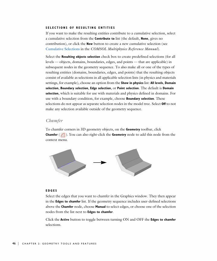
46 | C H A P T E R
S E L E C T I O N S O F R E S U L T I N G E N T I T I E S
If you want to make the resulting entities contribute to a cumulative selection, select a cumulative selection from the Contribute to list (the default, None, gives no contribution), or click the New button to create a new cumulative selection (see Cumulative Selections in the COMSOL Multiphysics Reference Manual).
Select the Resulting objects selection check box to create predefined selections (for all levels — objects, domains, boundaries, edges, and points — that are applicable) in subsequent nodes in the geometry sequence. To also make all or one of the types of resulting entities (domains, boundaries, edges, and points) that the resulting objects consist of available as selections in all applicable selection lists (in physics and materials settings, for example), choose an option from the Show in physics list: All levels, Domain
selection, Boundary selection, Edge selection, or Point selection. The default is Domain
selection, which is suitable for use with materials and physics defined in domains. For use with a boundary condition, for example, choose Boundary selection. These selections do not appear as separate selection nodes in the model tree. Select Off to not make any selection available outside of the geometry sequence.
Chamfer
To chamfer corners in 3D geometry objects, on the Geometry toolbar, click Chamfer ( ). You can also right-click the Geometry node to add this node from the context menu.
E D G E S
Select the edges that you want to chamfer in the Graphics window. They then appear in the Edges to chamfer list. If the geometry sequence includes user-defined selections above the Chamfer node, choose Manual to select edges, or choose one of the selection nodes from the list next to Edges to chamfer.
Click the Active button to toggle between turning ON and OFF the Edges to chamfer selections.
2 : G E O M E T R Y T O O L S A N D F E A T U R E S

R A D I U S
Enter the Radius of the chamfer. The size of the chamfer is determined by rolling a ball of the given radius so that it is tangent to the faces that are adjacent to the edge. The chamfer surface is generated by the line segment that connects the points of tangency.
O P T I O N S
Select or clear the following check boxes as needed.
• If the Propagate to tangent edges check box is selected, the chamfer is propagated to edges that have continuous tangent to the edges selected in Edges to chamfer.
• If the Preserve overlapped entities check box is selected, geometric features such as holes and bosses on faces that are overlapped by the chamfer surface are preserved.
• Select the Y-shaped chamfer check box to get a y-shaped chamfer at a vertex where three or more edges meet and there are two chamfer surfaces of different convexity. In some cases, using this option is necessary for the operation to succeed.
S E L E C T I O N S O F R E S U L T I N G E N T I T I E S
If you want to make the resulting entities contribute to a cumulative selection, select a cumulative selection from the Contribute to list (the default, None, gives no contribution), or click the New button to create a new cumulative selection (see Cumulative Selections in the COMSOL Multiphysics Reference Manual).
Select the Resulting objects selection check box to create predefined selections (for all levels — objects, domains, boundaries, edges, and points — that are applicable) in subsequent nodes in the geometry sequence. To also make all or one of the types of resulting entities (domains, boundaries, edges, and points) that the resulting objects consist of available as selections in all applicable selection lists (in physics and materials settings, for example), choose an option from the Show in physics list: All levels, Domain
selection, Boundary selection, Edge selection, or Point selection. The default is Domain
selection, which is suitable for use with materials and physics defined in domains. For use with a boundary condition, for example, choose Boundary selection. These selections do not appear as separate selection nodes in the model tree. Select Off to not make any selection available outside of the geometry sequence.
Delete Faces
To delete and replace faces from an object, from the Geometry toolbar, CAD Defeaturing menu, select Delete Faces ( ). This opens the Delete Faces window. When the
G E O M E T R Y F E A T U R E S | 47

48 | C H A P T E R
deletion operation has been performed, you can modify it by editing the corresponding Delete Faces node that appears in the geometry branch by clicking it.
D E L E T E F A C E S
In the Faces to delete list, select the faces you want to delete. In the Heal method list, select the method to use for replacing the deleted faces: Fill means that the deleted faces are replaced with a new face, while Patch means that the adjacent faces are grown or shrunk to heal the wound. Select the Heal as through hole check box if you have selected faces that make up a hole that you want to delete.
S E L E C T I O N S O F R E S U L T I N G E N T I T I E S
If you want to make the resulting entities contribute to a cumulative selection, select a cumulative selection from the Contribute to list (the default, None, gives no contribution), or click the New button to create a new cumulative selection (see Cumulative Selections in the COMSOL Multiphysics Reference Manual).
Select the Resulting objects selection check box to create predefined selections (for all levels — objects, domains, boundaries, edges, and points — that are applicable) in subsequent nodes in the geometry sequence. To also make all or one of the types of resulting entities (domains, boundaries, edges, and points) that the resulting objects consist of available as selections in all applicable selection lists (in physics and materials settings, for example), choose an option from the Show in physics list: All levels, Domain
selection, Boundary selection, Edge selection, or Point selection. The default is Domain
selection, which is suitable for use with materials and physics defined in domains. For use with a boundary condition, for example, choose Boundary selection. These selections do not appear as separate selection nodes in the model tree. Select Off to not make any selection available outside of the geometry sequence.
Delete Fillets
To delete fillets from an object, from the Geometry toolbar, Defeaturing and Repair menu, select Delete Fillets ( ). This opens the Delete Fillets window, see Finding and Deleting Small Details. When the deletion operation has been performed, you can
The Delete Faces tool can only be applied to objects that are represented by the Parasolid® geometry kernel, also called CAD objects.
2 : G E O M E T R Y T O O L S A N D F E A T U R E S
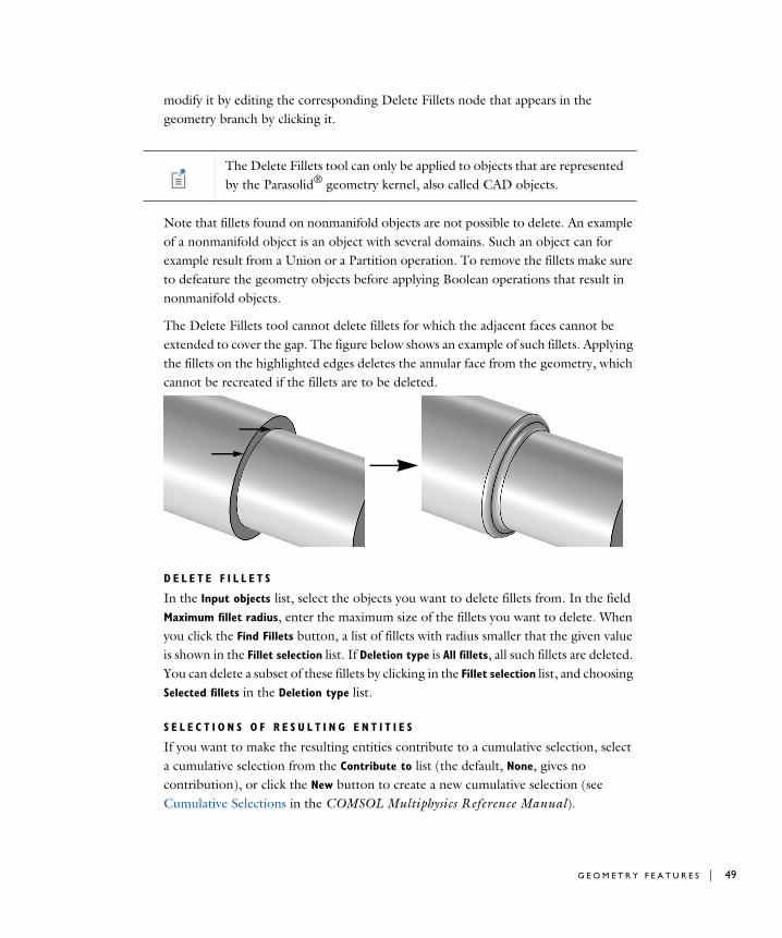
modify it by editing the corresponding Delete Fillets node that appears in the geometry branch by clicking it.
Note that fillets found on nonmanifold objects are not possible to delete. An example of a nonmanifold object is an object with several domains. Such an object can for example result from a Union or a Partition operation. To remove the fillets make sure to defeature the geometry objects before applying Boolean operations that result in nonmanifold objects.
The Delete Fillets tool cannot delete fillets for which the adjacent faces cannot be extended to cover the gap. The figure below shows an example of such fillets. Applying the fillets on the highlighted edges deletes the annular face from the geometry, which cannot be recreated if the fillets are to be deleted.
D E L E T E F I L L E T S
In the Input objects list, select the objects you want to delete fillets from. In the field Maximum fillet radius, enter the maximum size of the fillets you want to delete. When you click the Find Fillets button, a list of fillets with radius smaller that the given value is shown in the Fillet selection list. If Deletion type is All fillets, all such fillets are deleted. You can delete a subset of these fillets by clicking in the Fillet selection list, and choosing Selected fillets in the Deletion type list.
S E L E C T I O N S O F R E S U L T I N G E N T I T I E S
If you want to make the resulting entities contribute to a cumulative selection, select a cumulative selection from the Contribute to list (the default, None, gives no contribution), or click the New button to create a new cumulative selection (see Cumulative Selections in the COMSOL Multiphysics Reference Manual).
The Delete Fillets tool can only be applied to objects that are represented by the Parasolid® geometry kernel, also called CAD objects.
G E O M E T R Y F E A T U R E S | 49
50 | C H A P T E R
Select the Resulting objects selection check box to create predefined selections (for all levels — objects, domains, boundaries, edges, and points — that are applicable) in subsequent nodes in the geometry sequence. To also make all or one of the types of resulting entities (domains, boundaries, edges, and points) that the resulting objects consist of available as selections in all applicable selection lists (in physics and materials settings, for example), choose an option from the Show in physics list: All levels, Domain
selection, Boundary selection, Edge selection, or Point selection. The default is Domain
selection, which is suitable for use with materials and physics defined in domains. For use with a boundary condition, for example, choose Boundary selection. These selections do not appear as separate selection nodes in the model tree. Select Off to not make any selection available outside of the geometry sequence.
Delete Holes
To delete cylindrical holes from an object, from the Geometry toolbar, Defeaturing and
Repair menu, select Delete Holes ( ). This opens the Delete Holes window, see Finding and Deleting Small Details. When the deletion operation has been performed, you can modify it by editing the corresponding Delete Fillets node that appears in the geometry branch by clicking it.
Note that holes found on nonmanifold objects are not possible to delete. An example of a nonmanifold object is an object with several domains. Such an object can for example result from a Union or a Partition operation. To remove the holes make sure to defeature the geometry objects before applying Boolean operations that result in nonmanifold objects.
D E L E T E H O L E S
In the Input objects list, select the objects you want to delete holes from. In the field Maximum hole radius, enter the maximum size of the holes you want to delete. When you click the Find Holes button, a list of holes with radius smaller that the given value is shown in the Hole selection list. If Deletion type is All holes, all such holes are deleted. You can delete a subset of these holes by clicking in the Hole selection list, and choosing Selected holes in the Deletion type list.
The Delete Holes tool can only be applied to objects that are represented by the CAD kernel; see Converting Objects to CAD Kernel Representation.
2 : G E O M E T R Y T O O L S A N D F E A T U R E S

S E L E C T I O N S O F R E S U L T I N G E N T I T I E S
If you want to make the resulting entities contribute to a cumulative selection, select a cumulative selection from the Contribute to list (the default, None, gives no contribution), or click the New button to create a new cumulative selection (see Cumulative Selections in the COMSOL Multiphysics Reference Manual).
Select the Resulting objects selection check box to create predefined selections (for all levels — objects, domains, boundaries, edges, and points — that are applicable) in subsequent nodes in the geometry sequence. To also make all or one of the types of resulting entities (domains, boundaries, edges, and points) that the resulting objects consist of available as selections in all applicable selection lists (in physics and materials settings, for example), choose an option from the Show in physics list: All levels, Domain
selection, Boundary selection, Edge selection, or Point selection. The default is Domain
selection, which is suitable for use with materials and physics defined in domains. For use with a boundary condition, for example, choose Boundary selection. These selections do not appear as separate selection nodes in the model tree. Select Off to not make any selection available outside of the geometry sequence.
Delete Short Edges
To delete short edges from an object, from the Geometry toolbar, Defeaturing and
Repair menu, select Delete Short Edges ( ). This opens the Delete Short Edges window, see Finding and Deleting Small Details. When the deletion operation has been performed, you can modify it by editing the corresponding Delete Short Edges node that appears in the geometry branch by clicking it.
Note that this defeaturing tool cannot find short edges on nonmanifold objects. An example of a nonmanifold object is an object with several domains. Such an object can for example result from a Union or a Partition operation. To avoid this situation defeature the geometry objects before applying Boolean operations that result in nonmanifold objects.
D E L E T E S H O R T E D G E S
In the Input objects list, select the objects you want to delete short edges from. In the field Maximum edge length, enter the maximum length of the edges you want to delete. When you click the Find Short Edges button, a list of edges with length smaller that the
The Delete Short Edges tool can only be applied to objects that are represented by the Parasolid® geometry kernel, also called CAD objects.
G E O M E T R Y F E A T U R E S | 51

52 | C H A P T E R
given value is shown in the Short edge selection list. If Deletion type is All short edges, all such edges are deleted. You can delete a subset of these edges by clicking in the Short
edge selection list, and choosing Selected short edges in the Deletion type list.
S E L E C T I O N S O F R E S U L T I N G E N T I T I E S
If you want to make the resulting entities contribute to a cumulative selection, select a cumulative selection from the Contribute to list (the default, None, gives no contribution), or click the New button to create a new cumulative selection (see Cumulative Selections in the COMSOL Multiphysics Reference Manual).
Select the Resulting objects selection check box to create predefined selections (for all levels — objects, domains, boundaries, edges, and points — that are applicable) in subsequent nodes in the geometry sequence. To also make all or one of the types of resulting entities (domains, boundaries, edges, and points) that the resulting objects consist of available as selections in all applicable selection lists (in physics and materials settings, for example), choose an option from the Show in physics list: All levels, Domain
selection, Boundary selection, Edge selection, or Point selection. The default is Domain
selection, which is suitable for use with materials and physics defined in domains. For use with a boundary condition, for example, choose Boundary selection. These selections do not appear as separate selection nodes in the model tree. Select Off to not make any selection available outside of the geometry sequence.
Delete Sliver Faces
To delete sliver faces from an object, from the Geometry toolbar, Defeaturing and Repair menu, select Delete Sliver Faces ( ). This opens the Delete Sliver Faces window, see Finding and Deleting Small Details. When the deletion operation has been performed, you can modify it by editing the corresponding Delete Sliver Faces node that appears in the geometry branch by clicking it.
Note that this defeaturing tool cannot find sliver faces on nonmanifold objects. An example of a nonmanifold object is an object with several domains. Such an object can for example result from a Union or a Partition operation. To avoid this situation defeature the geometry objects before applying Boolean operations that result in nonmanifold objects.
The Delete Sliver Faces tool can only be applied to objects that are represented by the Parasolid® geometry kernel, also called CAD objects.
2 : G E O M E T R Y T O O L S A N D F E A T U R E S

D E L E T E S L I V E R F A C E S
In the Input objects list, select the objects you want to delete sliver faces from. In the field Maximum face width, enter the maximum width of the faces you want to delete. When you click the Find Sliver Faces button, a list of faces with width smaller that the given value are shown in the Sliver faces selection list. If Deletion type is All sliver faces, all such faces are deleted. You can delete a subset of these faces by clicking in the Sliver face selection list, and choosing Selected sliver faces in the Deletion type list.
S E L E C T I O N S O F R E S U L T I N G E N T I T I E S
If you want to make the resulting entities contribute to a cumulative selection, select a cumulative selection from the Contribute to list (the default, None, gives no contribution), or click the New button to create a new cumulative selection (see Cumulative Selections in the COMSOL Multiphysics Reference Manual).
Select the Resulting objects selection check box to create predefined selections (for all levels — objects, domains, boundaries, edges, and points — that are applicable) in subsequent nodes in the geometry sequence. To also make all or one of the types of resulting entities (domains, boundaries, edges, and points) that the resulting objects consist of available as selections in all applicable selection lists (in physics and materials settings, for example), choose an option from the Show in physics list: All levels, Domain
selection, Boundary selection, Edge selection, or Point selection. The default is Domain
selection, which is suitable for use with materials and physics defined in domains. For use with a boundary condition, for example, choose Boundary selection. These selections do not appear as separate selection nodes in the model tree. Select Off to not make any selection available outside of the geometry sequence.
Delete Small Faces
To delete small faces from an object, from the Geometry toolbar, Defeaturing and Repair menu, select Delete Small Faces ( ). This opens the Delete Small Faces window, see Finding and Deleting Small Details. When the deletion operation has been performed, you can modify it by editing the corresponding Delete Small Faces node that appears in the geometry branch by clicking it.
Note that this defeaturing tool cannot find small faces on nonmanifold objects. An example of a nonmanifold object is an object with several domains. Such an object can
The Delete Small Faces tool can only be applied to objects that are represented by the Parasolid® geometry kernel, also called CAD objects.
G E O M E T R Y F E A T U R E S | 53
54 | C H A P T E R
for example result from a Union or a Partition operation. To avoid this situation defeature the geometry objects before applying Boolean operations that result in nonmanifold objects.
D E L E T E S M A L L F A C E S
In the Input objects list, select the objects you want to delete small faces from. In the field Maximum face size, enter the maximum diameter of the faces you want to delete. When you click the Find Small Faces button, a list of faces with diameter smaller that the given value appears in the Small faces selection list. If Deletion type is All small faces, all such faces are deleted. You can delete a subset of these faces by clicking in the Small
face selection list, and choosing Selected small faces in the Deletion type list.
S E L E C T I O N S O F R E S U L T I N G E N T I T I E S
If you want to make the resulting entities contribute to a cumulative selection, select a cumulative selection from the Contribute to list (the default, None, gives no contribution), or click the New button to create a new cumulative selection (see Cumulative Selections in the COMSOL Multiphysics Reference Manual).
Select the Resulting objects selection check box to create predefined selections (for all levels — objects, domains, boundaries, edges, and points — that are applicable) in subsequent nodes in the geometry sequence. To also make all or one of the types of resulting entities (domains, boundaries, edges, and points) that the resulting objects consist of available as selections in all applicable selection lists (in physics and materials settings, for example), choose an option from the Show in physics list: All levels, Domain
selection, Boundary selection, Edge selection, or Point selection. The default is Domain
selection, which is suitable for use with materials and physics defined in domains. For use with a boundary condition, for example, choose Boundary selection. These selections do not appear as separate selection nodes in the model tree. Select Off to not make any selection available outside of the geometry sequence.
Delete Spikes
A spike is a long and narrow protrusion on an edge or corner of a face defined by two or three edges. To delete spikes from an object, from the Geometry toolbar, Defeaturing
and Repair menu, select Delete Spikes ( ). This opens the Delete Spikes window, see Finding and Deleting Small Details. When the deletion operation has been performed,
2 : G E O M E T R Y T O O L S A N D F E A T U R E S

you can modify it by editing the corresponding Delete Spikes node that appears in the geometry branch by clicking it.
Note that this defeaturing tool cannot find spikes on faces that belong to nonmanifold objects. An example of a nonmanifold object is an object with several domains. Such an object can for example result from a Union or a Partition operation. To avoid this situation defeature the geometry objects before applying Boolean operations that result in nonmanifold objects.
D E L E T E S P I K E S
In the Input objects list, select the objects you want to delete spikes from. In the field Maximum spike width, enter the maximum width of the spikes you want to delete. When you click the Find Spikes button, a list of spikes with width smaller that the given value are shown in the Spike selection list. If Deletion type is All spikes, all such spikes are deleted. You can delete a subset of these spikes by clicking in the Spike selection list, and choosing Selected spikes in the Deletion type list.
S E L E C T I O N S O F R E S U L T I N G E N T I T I E S
If you want to make the resulting entities contribute to a cumulative selection, select a cumulative selection from the Contribute to list (the default, None, gives no contribution), or click the New button to create a new cumulative selection (see Cumulative Selections in the COMSOL Multiphysics Reference Manual).
Select the Resulting objects selection check box to create predefined selections (for all levels — objects, domains, boundaries, edges, and points — that are applicable) in subsequent nodes in the geometry sequence. To also make all or one of the types of resulting entities (domains, boundaries, edges, and points) that the resulting objects consist of available as selections in all applicable selection lists (in physics and materials settings, for example), choose an option from the Show in physics list: All levels, Domain
selection, Boundary selection, Edge selection, or Point selection. The default is Domain
selection, which is suitable for use with materials and physics defined in domains. For use with a boundary condition, for example, choose Boundary selection. These selections do not appear as separate selection nodes in the model tree. Select Off to not make any selection available outside of the geometry sequence.
The Delete Spikes tool can only be applied to objects that are represented by the Parasolid® geometry kernel, also called CAD objects.
G E O M E T R Y F E A T U R E S | 55

56 | C H A P T E R
Detach Faces
To detach faces from an object (the parent) and form a new object (the child), from the Geometry toolbar, Defeaturing and Repair menu, select Detach Faces ( ). This opens the Detach Faces window. When the detach operation has been performed, you can modify it by editing the corresponding Detach Faces node that appears in the geometry branch by clicking it.
D E T A C H F A C E S
Select the faces you want to detach in the Graphics window. They appear in the Faces to detach list.
The Parent heal method list determines how to replace the detached faces in the parent object: Fill means that a new face is constructed, and Patch means that the adjacent faces grow or shrink to heal the wound.
The Child heal method list controls how to construct the child solid from the detached faces: Fill means that a new face is formed based on the surrounding edges of each wound, Patch from child means that the detached faces are grown or shrunk to form a solid, and Patch from parent means that the parent faces surrounding the detached faces are grown or shrunk to form a solid together with the detached faces.
S E L E C T I O N S O F R E S U L T I N G E N T I T I E S
If you want to make the resulting entities contribute to a cumulative selection, select a cumulative selection from the Contribute to list (the default, None, gives no contribution), or click the New button to create a new cumulative selection (see Cumulative Selections in the COMSOL Multiphysics Reference Manual).
Select the Resulting objects selection check box to create predefined selections (for all levels — objects, domains, boundaries, edges, and points — that are applicable) in subsequent nodes in the geometry sequence. To also make all or one of the types of resulting entities (domains, boundaries, edges, and points) that the resulting objects consist of available as selections in all applicable selection lists (in physics and materials settings, for example), choose an option from the Show in physics list: All levels, Domain
selection, Boundary selection, Edge selection, or Point selection. The default is Domain
selection, which is suitable for use with materials and physics defined in domains. For
The Detach Faces tool can only be applied to objects that are represented by the Parasolid® geometry kernel, also called CAD objects.
2 : G E O M E T R Y T O O L S A N D F E A T U R E S

use with a boundary condition, for example, choose Boundary selection. These selections do not appear as separate selection nodes in the model tree. Select Off to not make any selection available outside of the geometry sequence.
Fillet
To fillet corners in 3D geometry objects, on the Geometry toolbar, click Fillet ( ). You can also right-click the Geometry node and add this node from the context menu.
The objects containing the selected edges must have manifold topology in the neighborhood of the selected edges. In particular, each edge must be adjacent to exactly two faces. When you build the feature, these adjacent faces are shrunk and a rolling ball fillet face is inserted in between. The new surface is generated by rolling a ball of the given radius so that it is tangent to both faces. The fillet face is therefore tangent to both original faces.
When more than two selected edges meet at a vertex, one or several additional patch faces are inserted at the vertex to get a smooth result.
If the radius is large, it can happen that the fillet face overflows the original faces. In this case the fillet face meets other, more distant, faces in the object.
E D G E S
Select the edges that you want to fillet in the Graphics window. They then appear in the Edges to fillet list. If the geometry sequence includes user-defined selections above the
G E O M E T R Y F E A T U R E S | 57

58 | C H A P T E R
Fillet node, choose Manual to select edges, or choose one of the selection nodes from the list next to Edges to fillet.
Click the Active button to toggle between turning ON and OFF the Edges to fillet selections.
R A D I U S
Enter the Radius of the fillet. The fillet surface is generated by rolling a ball of the given radius so that it is tangent to the faces adjacent to the edge.
O P T I O N S
Select or clear the following check boxes as needed.
• If the Propagate to tangent edges check box is selected, the fillet is propagated to edges that have continuous tangent to the edges selected in Edges to fillet.
• If the Preserve overlapped entities check box is selected, geometric features such as holes and bosses on faces that are overlapped by the fillet surface are preserved.
• Select the Y-shaped fillet check box to get a y-shaped fillet at a vertex where three or more edges meet and there are two fillet surfaces of different convexity. In some cases, using this option is necessary for the operation to succeed.
• Select the Fillet sharp edges at vertices check box to get a smooth fillet surface at vertices where two filleted edges intersect at an angle.
Y-shaped fillet selected
Y-shaped fillet cleared
2 : G E O M E T R Y T O O L S A N D F E A T U R E S

S E L E C T I O N S O F R E S U L T I N G E N T I T I E S
If you want to make the resulting entities contribute to a cumulative selection, select a cumulative selection from the Contribute to list (the default, None, gives no contribution), or click the New button to create a new cumulative selection (see Cumulative Selections in the COMSOL Multiphysics Reference Manual).
Select the Resulting objects selection check box to create predefined selections (for all levels — objects, domains, boundaries, edges, and points — that are applicable) in subsequent nodes in the geometry sequence. To also make all or one of the types of resulting entities (domains, boundaries, edges, and points) that the resulting objects consist of available as selections in all applicable selection lists (in physics and materials settings, for example), choose an option from the Show in physics list: All levels, Domain
selection, Boundary selection, Edge selection, or Point selection. The default is Domain
selection, which is suitable for use with materials and physics defined in domains. For use with a boundary condition, for example, choose Boundary selection. These selections do not appear as separate selection nodes in the model tree. Select Off to not make any selection available outside of the geometry sequence.
Knit to Solid
To knit surface objects to form solid objects, from the Geometry toolbar, Defeaturing
and Repair menu, select Knit to Solid ( ).
K N I T T O S O L I D
Select the objects to knit together in the Graphics window. They appear in the Input
objects list.
The knitting merges edges that have a distance smaller that the Absolute repair
tolerance and deletes gaps and spikes smaller than the Absolute repair tolerance. If the Fill holes check box is selected the operation attempts to generate new faces to replace missing geometry.
S E L E C T I O N S O F R E S U L T I N G E N T I T I E S
If you want to make the resulting entities contribute to a cumulative selection, select a cumulative selection from the Contribute to list (the default, None, gives no contribution), or click the New button to create a new cumulative selection (see Cumulative Selections in the COMSOL Multiphysics Reference Manual).
Select the Resulting objects selection check box to create predefined selections (for all levels — objects, domains, boundaries, edges, and points — that are applicable) in
G E O M E T R Y F E A T U R E S | 59
60 | C H A P T E R
subsequent nodes in the geometry sequence. To also make all or one of the types of resulting entities (domains, boundaries, edges, and points) that the resulting objects consist of available as selections in all applicable selection lists (in physics and materials settings, for example), choose an option from the Show in physics list: All levels, Domain
selection, Boundary selection, Edge selection, or Point selection. The default is Domain
selection, which is suitable for use with materials and physics defined in domains. For use with a boundary condition, for example, choose Boundary selection. These selections do not appear as separate selection nodes in the model tree. Select Off to not make any selection available outside of the geometry sequence.
Loft
To create a lofted object from a set of profiles in 3D, on the Geometry toolbar, click Loft ( ). You can also right-click the Geometry node and add this node from the context menu. Enter the properties of the loft operation according to the following sections.
Each profile is a chain or loop of edges, also called a profile curve. The profiles must be all open or all closed, and they must have the same number of edges. The output is a loft surface, which consists of one or several faces that interpolate the profiles. In the closed curve case, a profile can optionally contain a set of faces (with manifold topology) that is bounded by the profile curve. These faces can be added to the loft surface to give the resulting object. The start and end profiles can degenerate to a point. Also, in the closed profile case, the start and end profiles can degenerate to an open curve. The loft can be periodic, which means that the end profile should not be specified because it equals the start profile (in this case the degenerate profiles are not allowed).
There can also be curves in the lofting direction that the loft surface should interpolate; these are called guide curves. If there are no guide curves, there must be at least two profiles.
G E N E R A L
Select or clear the following check boxes as needed.
• Select the Periodic loft check box to create a periodic loft, for which the start and end profiles coincide.
• If the Unite with input objects check box is selected, the resulting object is the union of the loft surface with the objects containing the start and end profiles and the
2 : G E O M E T R Y T O O L S A N D F E A T U R E S

objects containing the start and end guide curves. The faces that might exist in the start and end profiles are always included in the resulting object.
• If the Keep intermediate profile faces check box is selected, faces in the intermediate profile objects are added to the resulting object. Any faces belonging to the start and end profiles are always kept.
• Select an Object type — Solid (the default) or Surface. This determines whether domains should be created in the resulting object.
• Select a Face partitioning:
- If Minimal (the default) is selected, the loft surface is divided along the loft direction only at vertices where the profile curve has a tangent discontinuity.
- If Columns is selected, the loft surface is divided along the loft direction at each vertex of the profile curves.
- If Grid is selected, in addition to the Columns partitioning, the loft surface is divided by the profile curves. The loft surface is always partitioned by the profile faces when Keep intermediate profile faces is selected.
P R O F I L E S
This section specifies the profiles that are not specified in the Start Profile or End Profile
sections.
Select the objects that you want to use as profiles in the Graphics window. You can select a set of connected surface objects, curve objects, or point objects. Surface objects must have manifold topology and be bounded by a single edge loop. Curve objects must be a single edge loop or chain. Point objects are only allowed for use as start or end profiles and must have a single vertex. The selected objects appear in the Profile
objects list. If the geometry sequence includes user-defined selections above the Loft node, choose Manual to select objects, or choose one of the selection nodes from the list next to Profile objects.
Click the Active button to toggle between turning ON and OFF the Profile objects selection.
S T A R T P R O F I L E
Use this section to specify the start profile in the following cases:
• If you want to explicitly specify which profile should be the start profile.
• If the start profile is part of a larger object.
• If you want to prescribe the direction of the loft surface on the start profile.
G E O M E T R Y F E A T U R E S | 61

62 | C H A P T E R
In other cases, you can specify the start profile in the Profiles section, and leave the selection in the Start Profile section empty.
Select a Geometric entity level for the profile — Object, Point, Edge, or Boundary. Click to select the entities in the Graphics window. An object selection must fulfill the requirements detailed in the Profiles section. A point selection must consist of a single point. An edge selection must form a single edge loop or chain. A boundary selection must have manifold topology and be bounded by a single edge loop. The selected entities appear in the Start profile list. If the geometry sequence includes user-defined selections above the Loft node, choose Manual to select objects or entities, or choose one of the selection nodes from the list next to Input objects.
Click the Active button to toggle between turning ON and OFF the Start profile selection.
Select a Loft direction — Not prescribed (the default), Parallel, Perpendicular, or At angle. For Parallel the loft direction is prescribed along the profile curve, while for Perpendicular or At angle it is only prescribed at the vertices on the profile curve.
Select Relative to — Adjacent faces (the default), Profile faces, or Profile edges’ plane. When At angle is selected, also enter an Angle (SI unit: deg).
• Adjacent faces are the faces that are adjacent to the profile edges and that are not contained in the Start profile selection.
• Profile faces are the faces contained in the Start profile selection.
• Profile edges’ plane means that the loft direction is prescribed in relation to the plane tangent to the profile’s edges at each vertex on the profile curve.
E N D P R O F I L E
The settings for this section are analogous to the Start Profile section. This section should not be used if the loft is periodic.
G U I D E C U R V E S
Use this section if you want to specify guide curves for the lofted object.
Select the objects that you want to use as guides in the Graphics window. You can select a set of curve objects. In the non-periodic case, each guide object must be a single edge chain. In the periodic case, each guide object must be a single edge loop. Each guide object must have continuous tangents and intersect each profile exactly once. The objects appear in the Guide objects list. If the geometry sequence includes user-defined
2 : G E O M E T R Y T O O L S A N D F E A T U R E S

selections above the Loft node, choose Manual to select objects, or choose one of the selection nodes from the list next to Guide objects.
Click the Active button to toggle between turning ON and OFF the Guide objects selection.
S T A R T G U I D E C U R V E S
Use this section to specify the start guide curve in the following cases:
• If the start guide curve is part of a larger object.
• If you want to prescribe the direction of the loft surface on the start guide curve.
In other cases, you can specify the start guide curve in the Guide Curves section, and leave the selection in the Start Guide Curve section empty.
The selected set of edges must form a single edge loop or chain, and fulfill the other requirements on a guide curve. Click the Active button to toggle between turning ON and OFF the Edges selection.
Select a Loft surface direction — Not prescribed (the default) or Parallel to adjacent faces, which means that the loft surface is prescribed to be tangent to the adjacent faces along the guide curve.
E N D G U I D E C U R V E S
The settings for this section are analogous to the Start Guide Curve. This section should not be used in the closed profile case.
S E L E C T I O N S O F R E S U L T I N G E N T I T I E S
If you want to make the resulting entities contribute to a cumulative selection, select a cumulative selection from the Contribute to list (the default, None, gives no contribution), or click the New button to create a new cumulative selection (see Cumulative Selections in the COMSOL Multiphysics Reference Manual).
Select the Resulting objects selection check box to create predefined selections (for all levels — objects, domains, boundaries, edges, and points — that are applicable) in subsequent nodes in the geometry sequence. To also make all or one of the types of resulting entities (domains, boundaries, edges, and points) that the resulting objects consist of available as selections in all applicable selection lists (in physics and materials settings, for example), choose an option from the Show in physics list: All levels, Domain
selection, Boundary selection, Edge selection, or Point selection. The default is Domain
selection, which is suitable for use with materials and physics defined in domains. For use with a boundary condition, for example, choose Boundary selection. These
G E O M E T R Y F E A T U R E S | 63
64 | C H A P T E R
selections do not appear as separate selection nodes in the model tree. Select Off to not make any selection available outside of the geometry sequence.
Midsurface
The Midsurface feature is the inverse of the Thicken feature (with symmetric offset). It removes the thickness of a solid object (having constant thickness), resulting in a surface object, which can be useful if you can use a Shell interface, for example, and model the physics on surfaces only.
On the Geometry toolbar, Conversions menu, click Midsurface ( ). You can also right-click the Geometry node and add this node from the Conversions submenu.
I N P U T
Select the objects that you want to use as input in the Graphics window. The objects appear in the Input objects list. A midsurface object is generated for each input object independently. If the geometry sequence includes user-defined selections above the Midsurface node, choose Manual to select objects, or choose one of the selection nodes from the list next to Input objects.
Click the Active button to toggle between turning ON and OFF the Input objects selection.
Select the Keep input objects check box to use the selected geometry objects for further geometry operations.
2 : G E O M E T R Y T O O L S A N D F E A T U R E S

O P T I O N S
Select the Repair overlaps check box to repair areas where two or more generated midsurfaces overlap.
Click to select the Split in smooth components check box as needed. If this is selected, each output object is split into components, where each component is of manifold type and has smooth normal vector.
S E L E C T I O N S O F R E S U L T I N G E N T I T I E S
If you want to make the resulting entities contribute to a cumulative selection, select a cumulative selection from the Contribute to list (the default, None, gives no contribution), or click the New button to create a new cumulative selection (see Cumulative Selections in the COMSOL Multiphysics Reference Manual).
Select the Resulting objects selection check box to create predefined selections (for all levels — objects, domains, boundaries, edges, and points — that are applicable) in subsequent nodes in the geometry sequence. To also make all or one of the types of resulting entities (domains, boundaries, edges, and points) that the resulting objects consist of available as selections in all applicable selection lists (in physics and materials settings, for example), choose an option from the Show in physics list: All levels, Domain
selection, Boundary selection, Edge selection, or Point selection. The default is Domain
selection, which is suitable for use with materials and physics defined in domains. For use with a boundary condition, for example, choose Boundary selection. These selections do not appear as separate selection nodes in the model tree. Select Off to not make any selection available outside of the geometry sequence.
Repair overlaps selected
Repair overlaps cleared
G E O M E T R Y F E A T U R E S | 65
66 | C H A P T E R
Repair
To repair objects, from the Geometry toolbar, Defeaturing and Repair menu, select Repair ( ).
R E P A I R
Select the objects to repair in the Graphics window. They appear in the Input objects list.
The software tries to repair defects and remove details smaller than the Absolute import
tolerance. More precisely:
• Entities with invalid sense
• Invalid edge and vertex tolerances
• Invalid manifolds
• Self-intersecting manifolds
• Non-G1 manifolds
• Missing edge or vertex manifolds
• Missing vertex
• Vertices not on curve of edge
• Edges and vertices not on surface of face
• Removal of surface self-intersections that lie outside the face
• Splitting at edge intersections which have no vertex
• Removal of discontinuities by either splitting or smoothing
• Remove small features (short edges, small faces, sliver faces, and spikes)
Select the option Simplify curves and surfaces to also simplify the underlying curve and surface manifolds of the geometric entities. Repairing objects with this option may help in some cases when Boolean operations on the objects fail.
S E L E C T I O N S O F R E S U L T I N G E N T I T I E S
If you want to make the resulting entities contribute to a cumulative selection, select a cumulative selection from the Contribute to list (the default, None, gives no contribution), or click the New button to create a new cumulative selection (see Cumulative Selections in the COMSOL Multiphysics Reference Manual).
Select the Resulting objects selection check box to create predefined selections (for all levels — objects, domains, boundaries, edges, and points — that are applicable) in subsequent nodes in the geometry sequence. To also make all or one of the types of
2 : G E O M E T R Y T O O L S A N D F E A T U R E S

resulting entities (domains, boundaries, edges, and points) that the resulting objects consist of available as selections in all applicable selection lists (in physics and materials settings, for example), choose an option from the Show in physics list: All levels, Domain
selection, Boundary selection, Edge selection, or Point selection. The default is Domain
selection, which is suitable for use with materials and physics defined in domains. For use with a boundary condition, for example, choose Boundary selection. These selections do not appear as separate selection nodes in the model tree. Select Off to not make any selection available outside of the geometry sequence.
Thicken
On the Geometry toolbar, Conversions menu, click Thicken ( ) to convert a surface object to a solid object by giving it a thickness (usually in the normal direction). You can also right-click the Geometry node and add this node from the Conversions submenu.
I N P U T
Select the objects that you want to thicken in the Graphics window. The objects appear in the Input objects list. Each input object is thickened independently. If the geometry sequence includes user-defined selections above the Thicken node, choose Manual to select objects, or choose one of the selection nodes from the list next to Input objects.
Click the Active button to toggle between turning ON and OFF the Input objects selections.
Select the Keep input objects check box to use the selected geometry objects for further geometry operations.
O P T I O N S
Select an Offset — Symmetric (the default) or Asymmetric.
If Symmetric is selected enter a Total thickness.
If Asymmetric is selected enter an Upside thickness and a Downside thickness.
Select the Fillet offset edges check box to fillet each convex edge joining two offset faces, using the offset distance as the fillet radius. This option applies only when the offset is single-sided; that is, when either the up or down thickness is set to 0.
For either choice, select a Direction — Normal (the default) or Vector. For Vector, and based on space dimension, enter values or expressions for x, y, and z (SI unit: m)
G E O M E T R Y F E A T U R E S | 67

68 | C H A P T E R
S E L E C T I O N S O F R E S U L T I N G E N T I T I E S
If you want to make the resulting entities contribute to a cumulative selection, select a cumulative selection from the Contribute to list (the default, None, gives no contribution), or click the New button to create a new cumulative selection (see Cumulative Selections in the COMSOL Multiphysics Reference Manual).
Select the Resulting objects selection check box to create predefined selections (for all levels — objects, domains, boundaries, edges, and points — that are applicable) in subsequent nodes in the geometry sequence. To also make all or one of the types of resulting entities (domains, boundaries, edges, and points) that the resulting objects consist of available as selections in all applicable selection lists (in physics and materials settings, for example), choose an option from the Show in physics list: All levels, Domain
selection, Boundary selection, Edge selection, or Point selection. The default is Domain
selection, which is suitable for use with materials and physics defined in domains. For use with a boundary condition, for example, choose Boundary selection. These selections do not appear as separate selection nodes in the model tree. Select Off to not make any selection available outside of the geometry sequence.
2 : G E O M E T R Y T O O L S A N D F E A T U R E S

3
P r o g r a m m i n g a n d C o m m a n d R e f e r e n c e
In this section you find detailed COMSOL® API reference information for the geometry features in the Design Module.
69

70 | C H A P T E R
De f e a t u r i n g T oo l s
To remove unnecessary details in objects imported from a 3D CAD file, you can use the defeaturing tools. You access these by typing:
model.component(<ctag>).geom(<tag>).defeaturing("Fillets");model.component(<ctag>).geom(<tag>).defeaturing("Holes");model.component(<ctag>).geom(<tag>).defeaturing("ShortEdges");model.component(<ctag>).geom(<tag>).defeaturing("SliverFaces");model.component(<ctag>).geom(<tag>).defeaturing("SmallFaces");model.component(<ctag>).geom(<tag>).defeaturing("Spikes");model.component(<ctag>).geom(<tag>).defeaturing("DeleteFaces");model.component(<ctag>).geom(<tag>).defeaturing("DetachFaces");
Using the defeaturing tools you can search for small details, without altering your geometry. If you find small details that you want to remove, a defeaturing tool can create a feature that removes the details from the geometry.
The features corresponding to the defeaturing tools are DeleteFillets, DeleteHoles, DeleteShortEdges, DeleteSliverFaces, DeleteSmallFaces, DeleteSpikes, DeleteFaces, and DetachFaces. If you already know which details you need to remove, it is also possible to create these features directly using the standard create syntax.
This section includes these topics:
• Defeaturing Tools — Finding and Deleting Small Details
• Defeaturing Tools — Delete Faces
• Defeaturing Tools — Detach Faces
Defeaturing Tools — Finding and Deleting Small Details
The defeaturing tools Fillets, Holes, ShortEdges, SliverFaces, SmallFaces, and Spikes search for and delete details smaller than a given size. First select the objects you want to examine by typing, for example,
model.component(<ctag>).geom(<tag>).defeaturing("Fillets"). selection("input").set(<onames>);
where <onames> is a string array contains the object names.
Set the maximum size of the details (fillets in this case) you want to remove by typing
3 : P R O G R A M M I N G A N D C O M M A N D R E F E R E N C E

model.component(<ctag>).geom(<tag>).defeaturing("Fillets").set("entsize",size);
To find the details that are smaller than the given size, type
model.component(<ctag>).geom(<tag>).defeaturing("Fillets").find();
The found details appear in the selection
model.component(<ctag>).geom(<tag>).defeaturing("Fillets").detail();
To get the number of found details, type
int nd = model.component(<ctag>).geom(<tag>).defeaturing("Fillets").detail().size();
To get the names of the found details, type
String[] filletNames = model.component(<ctag>).geom(<tag>).defeaturing("Fillets").detail().groupNames();
In general, a detail (fillet in this case) consists of a number of geometric entities. For example, a fillet consists of a number of faces. To get the entity numbers in the nth detail, type
int[] entities = model.component(<ctag>).geom(<tag>). defeaturing("Fillets").detail().groupEntities(n);
To get the object that contains the nth detail, type
String oname = model.component(<ctag>).geom(<tag>).defeaturing("Fillets").detail().groupObject(n);
To delete all details found, type
model.component(<ctag>).geom(<tag>).defeaturing("Fillets").deleteAll(<ftag>);
This adds a feature, tagged <ftag>, that performs the deletion operation to the geometry sequence, after the current feature, and build this feature. In this case, it adds a DeleteFillets feature.
To delete a subset of the details found, type, for example
model.component(<ctag>).geom(<tag>).defeaturing("Fillets").detail().setGroup(2,5);
to delete fillets number 2 and 5. You can also use, for example,
model.component(<ctag>).geom(<tag>).defeaturing("Fillets").detail().addGroup(7,8);
D E F E A T U R I N G T O O L S | 71

72 | C H A P T E R
model.component(<ctag>).geom(<tag>).defeaturing("Fillets").detail().removeGroup(3);
to add and remove details from the selection. Perform the deletion by typing
model.component(<ctag>).geom(<tag>).defeaturing("Fillets").delete(<ftag>);
This adds a DeleteFillets feature tagged <ftag> after the current feature in the geometry sequence.
D E F E A T U R I N G M E T H O D S
model.component(<ctag>).geom(<tag>).feature(<ftag>).find() searches for small details, for a defeaturing feature <ftag>.
model.component(<ctag>).geom(<tag>).defeaturing(tooltag).find() searches for small details, for a defeaturing tool tooltag.
model.component(<ctag>).geom(<tag>).defeaturing(tooltag).detail().
selMethod manipulates the selection of details to remove, for a defeaturing tool tooltag.
model.component(<ctag>).geom(<tag>).feature(<ftag>).detail().
selMethod manipulates the selection of details to remove, for a defeaturing feature <ftag>.
model.component(<ctag>).geom(<tag>).defeaturing(tooltag).
delete(<ftag>) creates a defeaturing feature of type tooltag, tagged <ftag>, with the properties currently specified in the defeaturing tool. The property delete of the created feature is set to selected. If the feature <ftag> can be built, it is inserted in the geometry sequence after the current feature, otherwise the feature is discarded.
model.component(<ctag>).geom(<tag>).defeaturing(tooltag).
deleteAll(<ftag>) creates a defeaturing feature of type tooltag, tagged <ftag>, with the properties currently specified in the defeaturing tool. The property delete of the created feature is set to all. If the feature <ftag> can be built, it is inserted in the geometry sequence after the current feature, otherwise the feature is discarded.
3 : P R O G R A M M I N G A N D C O M M A N D R E F E R E N C E

D E F E A T U R I N G S E L E C T I O N M E T H O D S
For a defeaturing selection sel the following methods are available, in addition to the methods available for a general geometry selection.
The find method on the corresponding feature or defeaturing tool provides the defeaturing selection with a list of details. Each detail is a group of geometric entities. Group numbers, <groups>, is an array of integers that index into the list of details.
You can select groups either by explicitly referring to group numbers, or by selecting geometric entities. In the latter case, any group that has non-empty intersection with the provided entity selection is selected.
int[] sel.group(<groups>) returns the group numbers for the selected groups.
sel.addGroup(<groups>) adds the specified groups to the selection.
sel.setGroup(<groups>) sets the selection groups.
sel.removeGroup(<groups>) removes the specified groups from the selection.
String[] sel.groupNames() returns a list of names of the groups found.
String sel.groupObject(<group>) returns the name of the geometry object that contains the specified detail group.
int[] sel.groupEntities(<group>) returns the entity numbers of the specified detail group.
int sel.size() returns the number of detail groups found.
Defeaturing Tools — Delete Faces
Use the DeleteFaces tool to delete faces and replace them either with a new face or by growing or shrinking the adjacent faces. Select the faces to delete and properties for the operation like in the corresponding feature DeleteFaces. The deletion is performed when you issue the command
model.component(<ctag>).geom(<tag>).defeaturing("DeleteFaces").delete(<ftag>);
Geometry Object Selection Methods in the COMSOL Multiphysics Programming Reference Manual
D E F E A T U R I N G T O O L S | 73

74 | C H A P T E R
This adds a DeleteFaces feature tagged <ftag> after the current feature in the geometry sequence.
Defeaturing Tools — Detach Faces
Use the DetachFaces tool to detach faces from a solid object (the parent) to form a new solid object (the child). Select the faces to detach and properties for the operation like in the corresponding feature DetachFaces. The detach operation is performed when you issue the command
model.component(<ctag>).geom(<tag>).defeaturing("DetachFaces").delete(<ftag>);
3 : P R O G R A M M I N G A N D C O M M A N D R E F E R E N C E
S umma r y o f C ommand s
• Angle
• Array
• BezierPolygon
• CapFaces
• Chamfer
• Chamfer3D
• Circle
• CircularArc
• Coincident
• Concentric
• ConvertToCOMSOL
• Copy
• CubicBezier
• DeleteFaces
• DeleteFillets
• DeleteHoles
• DeleteShortEdges
• DeleteSliverFaces
• DeleteSmallFaces
• DeleteSpikes
• DetachFaces
• DirectedDistance
• Distance
• Ellipse
• EqualDistance
• EqualRadius
• Export, ExportFinal
• Fillet
• Fillet3D
• Import
• InterpolationCurve
• Knit
• LineSegment
• Loft
• Midsurface
• Mirror
• Move
• Parallel
• Perpendicular
• Point
• Polygon
• Position
• QuadraticBezier
• Radius
• Rectangle
• Repair
• Rotate
• Scale
• Square
• TangentConstraint
• Thicken
• TotalEdgeLength
• XDistance
• YDistance
S U M M A R Y O F C O M M A N D S | 75

76 | C H A P T E R
Command s G r oup ed b y Fun c t i o n
Commands for Creating and Modifying Geometry in 2DThe Design Module enables on/off properties for constraining the other properties of 2D geometric primitive and operation commands. The property name is obtained by appending constr to available property names. The default is on in operation features and usually off in primitive features. A constrained property cannot be modified by constraint and dimension commands. Properties that do not have a constr property are always constrained. With the Design Module some features also have properties for controlling a corresponding symbol in the Graphics window.
The following 2D geometry features get additional properties with the Design Module.
• Array
• BezierPolygon
• Chamfer
• Circle
• CircularArc
• Copy
• CubicBezier
• Ellipse
• Fillet
• InterpolationCurve
• LineSegment
• Mirror
• Move
• Point
• Polygon
• QuadraticBezier
• Rectangle
• Rotate
• Scale
• Square
3 : P R O G R A M M I N G A N D C O M M A N D R E F E R E N C E

Commands for Creating Constraints in 2D
Commands for Creating Dimensions in 2D
Commands for Defeaturing
FUNCTION PURPOSE
Coincident Constrain two geometric entities to coincide with each other
Concentric Constrain circular edges and vertices to have the same center
EqualDistance Constrain the distances between two pairs of geometric entities to be equal
EqualRadius Constrain two circular edges to have the same radius
Parallel Constrain straight edges to be parallel
Perpendicular Constrain two straight edges to be perpendicular
TangentConstraint Constrain two edges to be tangent
FUNCTION PURPOSE
Angle Constrain the angle between two edges
DirectedDistance Constrain the distance between two geometric entities in a given direction
Distance Constrain the distance between two geometric entities
Position Constrain the x- and y-coordinates of a point
Radius Constrain the radius of a circular edge
TotalEdgeLength Constrain the total length for a set of edges
XDistance Constrain the distance in the x-direction between entities
YDistance Constrain the distance in the y-direction between entities
FUNCTION PURPOSE
DeleteFaces Delete faces from CAD objects and heal the wounds
DeleteFillets Find and delete fillets in CAD objects
C O M M A N D S G R O U P E D B Y F U N C T I O N | 77

78 | C H A P T E R
Commands for File Import, Export, Conversion and Repair
Commands for Geometry Creation and Modification
DeleteHoles Find and delete holes in CAD objects
DeleteShortEdges Find and delete short edges in CAD objects
DeleteSliverFaces Find and delete sliver faces in CAD objects
DeleteSmallFaces Find and delete small faces in CAD objects
DeleteSpikes Find and delete spikes in CAD objects
Export, ExportFinal Detach faces from CAD objects to form a new solid
FUNCTION PURPOSE
ConvertToCOMSOL Convert CAD Import Module geometry objects to COMSOL objects
Export, ExportFinal Export geometry objects to a 3D CAD file
Import Import geometry objects from a 3D CAD file
Knit Knit surface CAD objects to form solids or surface objects
Repair Repair CAD objects
FUNCTION PURPOSE
CapFaces Add cap faces to fill holes in CAD geometries
Chamfer3D Chamfer edges in 3D geometry objects
Fillet3D Fillet edges in 3D geometry objects
Loft Create a lofted surface through a set of profile curves
Midsurface Generate a surface object that is the midsurface of a solid object in 3D
Thicken Generate a solid object by thickening a surface object in 3D
FUNCTION PURPOSE
3 : P R O G R A M M I N G A N D C O M M A N D R E F E R E N C E

Command s i n A l p h ab e t i c a l O r d e r
Angle
P U R P O S E
Constrains two edges to meet at a given angle.
D E S C R I P T I O N
S E E A L S O
TangentConstraint
TABLE 3-1: AVAILABLE PROPERTIES
PROPERTY VALUE DEFAULT DESCRIPTION
edge1 Selection First edge
reverse1 on | off off Reverse the direction of the first ray
edge2 Selection Second edge
reverse2 on | off off Reverse the direction of the second ray
angle double 0 Angle
helppoint1 double[2] {0, 0} First help point
helppoint2 double[2] {0, 0} Second help point
arrowradius double NaN Radius of circular arrow symbol in the Graphics window
labelpos double 0.5 Relative label position along the arrow symbol in Graphics window
arrowint on | off on Display internal or external arrow in Graphics window
C O M M A N D S I N A L P H A B E T I C A L O R D E R | 79
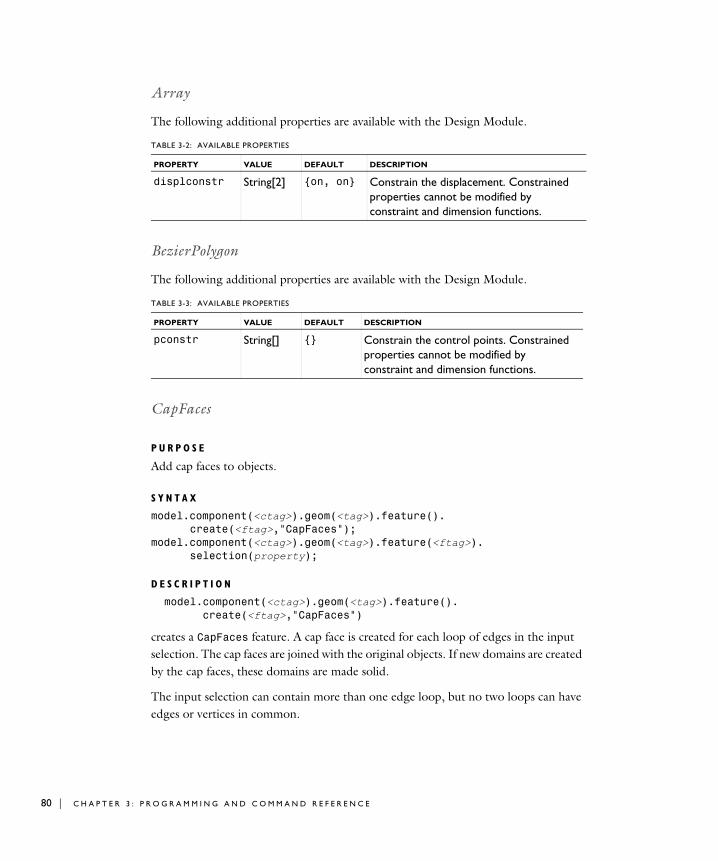
80 | C H A P T E R
Array
The following additional properties are available with the Design Module.
BezierPolygon
The following additional properties are available with the Design Module.
CapFaces
P U R P O S E
Add cap faces to objects.
S Y N T A X
model.component(<ctag>).geom(<tag>).feature().create(<ftag>,"CapFaces");
model.component(<ctag>).geom(<tag>).feature(<ftag>).selection(property);
D E S C R I P T I O N
model.component(<ctag>).geom(<tag>).feature().create(<ftag>,"CapFaces")
creates a CapFaces feature. A cap face is created for each loop of edges in the input selection. The cap faces are joined with the original objects. If new domains are created by the cap faces, these domains are made solid.
The input selection can contain more than one edge loop, but no two loops can have edges or vertices in common.
TABLE 3-2: AVAILABLE PROPERTIES
PROPERTY VALUE DEFAULT DESCRIPTION
displconstr String[2] {on, on} Constrain the displacement. Constrained properties cannot be modified by constraint and dimension functions.
TABLE 3-3: AVAILABLE PROPERTIES
PROPERTY VALUE DEFAULT DESCRIPTION
pconstr String[] {} Constrain the control points. Constrained properties cannot be modified by constraint and dimension functions.
3 : P R O G R A M M I N G A N D C O M M A N D R E F E R E N C E

The input selection can contain edges from more than one object. In this case, each object is processed individually.
Chamfer
The following additional properties are available with the Design Module.
Chamfer3D
Chamfer edges in 3D geometry objects.
S Y N T A X
model.component(<ctag>).geom(<tag>).feature().create(<ftag>,"Chamfer3D");
model.component(<ctag>).geom(<tag>).feature(<ftag>).selection(property);
model.component(<ctag>).geom(<tag>).feature(<ftag>).set(property,<value>);
model.component(<ctag>).geom(<tag>).feature(<ftag>).getType(property);
TABLE 3-4: AVAILABLE PROPERTIES
PROPERTY VALUE DEFAULT DESCRIPTION
input Selection The input edges.
selresult on | off off Create selections of all resulting objects.
selresultshow all | obj | dom | bnd | edg | pnt | off
dom Show selections of resulting objects in physics, materials, and so on, or in part instances. obj is not available in a component’s geometry. dom, bnd, and edg are not available in all features.
contributeto String none Tag of cumulative selection to contribute to.
TABLE 3-5: AVAILABLE PROPERTIES
PROPERTY VALUE DEFAULT DESCRIPTION
distconstr on | off off Constrain the distance. Constrained properties cannot be modified by constraint and dimension functions.
C O M M A N D S I N A L P H A B E T I C A L O R D E R | 81

82 | C H A P T E R
D E S C R I P T I O N
model.component(<ctag>).geom(<tag>).feature().create(<ftag>,"Chamfer3D")
creates a Chamfer3D feature.
Use model.component(<ctag>).geom(<tag>).feature(<ftag>).selection("edge") to select the edge to chamfer. The default selection is empty.
For information about the createselection and contributeto properties, search the online help in COMSOL Multiphysics to locate and search all the documentation.
E X A M P L E
Chamfer a subset of edges on a block:
Model model = ModelUtil.create("Model1");model.component().create("comp1");model.component("comp1").geom().create("geom1",3);model.component("comp1").geom("geom1").geomRep("cadps");model.component("comp1").geom("geom1").create("blk1", "Block");model.component("comp1").geom("geom1").
create("cha1", "Chamfer3D");
TABLE 3-6: AVAILABLE PROPERTIES
PROPERTY VALUE DEFAULT DESCRIPTION
edge Selection Edges to chamfer.
radius double 0 Radius.
propagate on | off on Propagate to tangent edges.
preserveoverlapped on | off off Preserve overlapped entities.
yshaped on | off off Y-shaped chamfer.
createselection on | off off Create selections.
selresult on | off off Create selections of all resulting objects.
selresultshow all | obj | dom | bnd | edg | pnt | off
dom Show selections of resulting objects in physics, materials, and so on, or in part instances. obj is not available in a component’s geometry. dom, bnd, and edg are not available in all features.
contributeto String none Tag of cumulative selection to contribute to.
3 : P R O G R A M M I N G A N D C O M M A N D R E F E R E N C E

model.component("comp1").geom("geom1").feature("cha1").selection("edge").set("blk1", new int[]{2, 4, 6, 8});
model.component("comp1").geom("geom1").feature("cha1").set("radius", "0.1");
model.component("comp1").geom("geom1").run();
S E E A L S O
Fillet3D
Circle
The following additional properties are available with the Design Module.
TABLE 3-7: AVAILABLE PROPERTIES
PROPERTY VALUE DEFAULT DESCRIPTION
rconstr on | off off Constrain the radius. Constrained properties cannot be modified by constraint and dimension functions.
angleconstr on | off on Constrain the sector angle. Constrained properties cannot be modified by constraint and dimension functions.
posconstr String[2] {off, off} Constrain the position. Constrained properties cannot be modified by constraint and dimension functions.
rotconstr on | off on Constrain the rotation angle. Constrained properties cannot be modified by constraint and dimension functions.
arrowangdispl double 0 Angular displacement of arrow symbol relative to middle of edge.
labelradius double 0.5 Relative label position along arrow symbol.
C O M M A N D S I N A L P H A B E T I C A L O R D E R | 83

84 | C H A P T E R
CircularArc
The following additional properties are available with the Design Module.
Coincident
P U R P O S E
Constrain two geometric entities to coincide with each other.
TABLE 3-8: AVAILABLE PROPERTIES
PROPERTY VALUE DEFAULT DESCRIPTION
centerconstr String[2] {off, off} Constrain the center. Constrained properties cannot be modified by constraint and dimension functions.
point1constr String[2] {off, off} Constrain the starting point. Constrained properties cannot be modified by constraint and dimension functions.
point2constr String[2] {off, off} Constrain the endpoint. Constrained properties cannot be modified by constraint and dimension functions.
rconstr on | off off Constrain the radius. Constrained properties cannot be modified by constraint and dimension functions.
angle1constr on | off off Constrain the start angle. Constrained properties cannot be modified by constraint and dimension functions.
angle2constr on | off off Constrain the end angle. Constrained properties cannot be modified by constraint and dimension functions.
3 : P R O G R A M M I N G A N D C O M M A N D R E F E R E N C E

D E S C R I P T I O N
Concentric
P U R P O S E
Constrain circular edges and vertices to have the same center.
TABLE 3-9: AVAILABLE PROPERTIES
PROPERTY VALUE DEFAULT DESCRIPTION
entity1 Selection First entity (vertex or edge)
entity2 Selection Second entity (vertex or edge)
helppoint1 double[2] {0, 0} First help point
helppoint2 double[2] {0, 0} Second help point
symbolentity 1 | 2 1 The entity the symbol in the Graphics window is attached to
symboledgpar double 0.5 Normalized edge parameter for positioning the symbol in the Graphics window
symboledgdispl double 20 Symbol displacement in left normal direction from edge (in pixels)
symbolvtxdispl double[2] {20, 20} Symbol displacement from vertex (in pixels)
C O M M A N D S I N A L P H A B E T I C A L O R D E R | 85
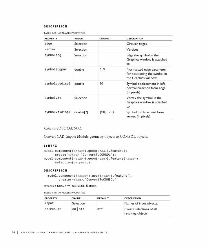
86 | C H A P T E R
D E S C R I P T I O N
ConvertToCOMSOL
Convert CAD Import Module geometry objects to COMSOL objects.
S Y N T A X
model.component(<ctag>).geom(<tag>).feature().create(<ftag>,"ConvertToCOMSOL");
model.component(<ctag>).geom(<tag>).feature(<ftag>).selection(property);
D E S C R I P T I O N
model.component(<ctag>).geom(<tag>).feature().create(<ftag>,"ConvertToCOMSOL")
creates a ConvertToCOMSOL feature.
TABLE 3-10: AVAILABLE PROPERTIES
PROPERTY VALUE DEFAULT DESCRIPTION
edge Selection Circular edges
vertex Selection Vertices
symboledg Selection Edge the symbol in the Graphics window is attached to
symboledgpar double 0.5 Normalized edge parameter for positioning the symbol in the Graphics window
symboledgdispl double 20 Symbol displacement in left normal direction from edge (in pixels)
symbolvtx Selection Vertex the symbol in the Graphics window is attached to
symbolvtxdispl double[2] {20, 20} Symbol displacement from vertex (in pixels)
TABLE 3-11: AVAILABLE PROPERTIES
PROPERTY VALUE DEFAULT DESCRIPTION
input Selection Names of input objects.
selresult on | off off Create selections of all resulting objects.
3 : P R O G R A M M I N G A N D C O M M A N D R E F E R E N C E

S E E A L S O
Import
Copy
The following additional properties are available with the Design Module.
CubicBezier
The following additional properties are available with the Design Module.
selresultshow all | obj | dom | bnd | edg | pnt | off
dom Show selections of resulting objects in physics, materials, and so on, or in part instances. obj is not available in a component’s geometry. dom, bnd, and edg are not available in all features.
contributeto String none Tag of cumulative selection to contribute to.
TABLE 3-12: AVAILABLE PROPERTIES
PROPERTY VALUE DEFAULT DESCRIPTION
displxconstr on | off on Constrain the x-displacement. Constrained properties cannot be modified by constraint and dimension functions.
displyconstr on | off on Constrain the y-displacement. Constrained properties cannot be modified by constraint and dimension functions.
TABLE 3-13: AVAILABLE PROPERTIES
PROPERTY VALUE DEFAULT DESCRIPTION
pconstr String[4] {off, off, off, off}
Constrain the control points. Constrained properties cannot be modified by constraint and dimension functions.
TABLE 3-11: AVAILABLE PROPERTIES
PROPERTY VALUE DEFAULT DESCRIPTION
C O M M A N D S I N A L P H A B E T I C A L O R D E R | 87

88 | C H A P T E R
DeleteFaces
Delete faces from CAD objects and heal the wounds.
S Y N T A X
model.component(<ctag>).geom(<tag>).feature().create(<ftag>,"DeleteFaces");
model.component(<ctag>).geom(<tag>).feature(<ftag>).selection(property);
model.component(<ctag>).geom(<tag>).feature(<ftag>).set(property,<value>);
model.component(<ctag>).geom(<tag>).feature(<ftag>).getType(property);
model.component(<ctag>).geom(<tag>).defeaturing("DeleteFaces").selection(property)
model.component(<ctag>).geom(<tag>).defeaturing("DeleteFaces"). set(property,<value>);model.component(<ctag>).geom(<tag>).defeaturing("DeleteFaces").dele
te(<ftag>);
D E S C R I P T I O N
model.component(<ctag>).geom(<tag>).defeaturing("DeleteFaces").
delete(<ftag>) creates a DeleteFaces feature tagged <ftag> with the specified properties. If the feature can be built, it is inserted in the geometry sequence after the current feature; otherwise, the feature is discarded.
It is also possible to create a DeleteFaces feature using the standard create method.
TABLE 3-14: AVAILABLE PROPERTIES
PROPERTY VALUE DEFAULT DESCRIPTION
input Selection Faces to delete.
heal fill | patch patch Healing method.
throughhole on | off off Heal as if the removed faces are a through hole.
selresult on | off off Create selections of all resulting objects.
3 : P R O G R A M M I N G A N D C O M M A N D R E F E R E N C E
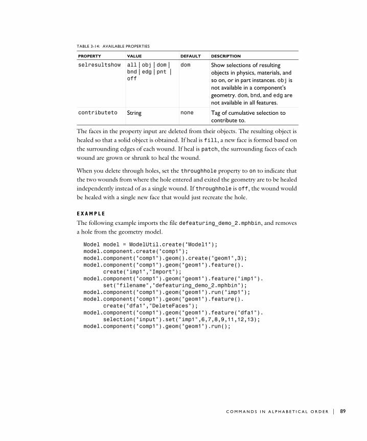
The faces in the property input are deleted from their objects. The resulting object is healed so that a solid object is obtained. If heal is fill, a new face is formed based on the surrounding edges of each wound. If heal is patch, the surrounding faces of each wound are grown or shrunk to heal the wound.
When you delete through holes, set the throughhole property to on to indicate that the two wounds from where the hole entered and exited the geometry are to be healed independently instead of as a single wound. If throughhole is off, the wound would be healed with a single new face that would just recreate the hole.
E X A M P L E
The following example imports the file defeaturing_demo_2.mphbin, and removes a hole from the geometry model.
Model model = ModelUtil.create("Model1");model.component.create("comp1");model.component("comp1").geom().create("geom1",3);model.component("comp1").geom("geom1").feature().
create("imp1","Import");model.component("comp1").geom("geom1").feature("imp1").
set("filename","defeaturing_demo_2.mphbin");model.component("comp1").geom("geom1").run("imp1");model.component("comp1").geom("geom1").feature().
create("dfa1","DeleteFaces");model.component("comp1").geom("geom1").feature("dfa1").
selection("input").set("imp1",6,7,8,9,11,12,13);model.component("comp1").geom("geom1").run();
selresultshow all | obj | dom | bnd | edg | pnt | off
dom Show selections of resulting objects in physics, materials, and so on, or in part instances. obj is not available in a component’s geometry. dom, bnd, and edg are not available in all features.
contributeto String none Tag of cumulative selection to contribute to.
TABLE 3-14: AVAILABLE PROPERTIES
PROPERTY VALUE DEFAULT DESCRIPTION
C O M M A N D S I N A L P H A B E T I C A L O R D E R | 89

90 | C H A P T E R
C O M P A T I B I L I T Y
The following property is no longer supported:
S E E A L S O
DeleteFillets, DeleteSliverFaces, DeleteSmallFaces, Export, ExportFinal
DeleteFillets
Find and delete fillets in CAD objects.
S Y N T A X
model.geom(<tag>).feature().create(<ftag>,"DeleteFillets");model.geom(<tag>).feature(<ftag>).selection(property);model.geom(<tag>).feature(<ftag>).set(property,<value>);model.geom(<tag>).feature(<ftag>).getType(property);model.geom(<tag>).feature(<ftag>).find();model.geom(<tag>).feature(<ftag>).detail();
model.geom(<tag>).defeaturing("Fillets").selection(property);model.geom(<tag>).defeaturing("Fillets").set(property,<value>);model.geom(<tag>).defeaturing("Fillets").find();model.geom(<tag>).defeaturing("Fillets").detail();model.geom(<tag>).defeaturing("Fillets").delete(<ftag>);model.geom(<tag>).defeaturing("Fillets").deleteAll(<ftag>);
D E S C R I P T I O N
model.geom(<tag>).defeaturing("Fillets").delete(<ftag>) creates a DeleteFillets feature tagged <ftag> with the specified properties. The property delete is set to selected. If the feature can be built, it is inserted in the geometry sequence after the current feature; otherwise, the feature is discarded.
model.geom(<tag>).defeaturing("Fillets").deleteAll(<ftag>) works as the delete method, but the property delete is set to all.
TABLE 3-15: OBSOLETE PROPERTIES
PROPERTY VALUE DEFAULT DESCRIPTION
Out stx | ftx | ctx | ptx
none Output variables
3 : P R O G R A M M I N G A N D C O M M A N D R E F E R E N C E

It is also possible to create the DeleteFillets feature using the standard create method. The following properties are available..
model.geom(<tag>).feature(<ftag>).find() searches the input objects for fillets with radius less than entsize.
model.geom(<tag>).feature(<ftag>).detail() returns a selection object where you can select a subset of the fillets found.
The find and detail methods of model.geom(<tag>).defeaturing("Fillets") has the corresponding functionality for the defeaturing tool.
Only faces that can be deleted without invalidating the object are deleted. If a fillet was not possible to delete, a warning is given, accessible through model.geom(<tag>).feature(<ftag>).problem().
C O M P A T I B I L I T Y
The following property is no longer supported:
TABLE 3-16: AVAILABLE PROPERTIES
PROPERTY VALUE DEFAULT DESCRIPTION
delete all | selected selected Delete all fillets of given size, or a selection. Only available for the feature.
entsize double 1e-3 Maximum fillet radius.
input Selection Names of input objects.
selresult on | off off Create selections of all resulting objects.
selresultshow all | obj | dom | bnd | edg | pnt | off
dom Show selections of resulting objects in physics, materials, and so on, or in part instances. obj is not available in a component’s geometry. dom, bnd, and edg are not available in all features.
contributeto String none Tag of cumulative selection to contribute to.
TABLE 3-17: OBSOLETE PROPERTIES
PROPERTY VALUE DEFAULT DESCRIPTION
Out stx | ftx | ctx | ptx
none Output variables
C O M M A N D S I N A L P H A B E T I C A L O R D E R | 91

92 | C H A P T E R
E X A M P L E
The following example imports the CAD object in the COMSOL Multiphysics geometry file defeaturing_demo_3.mphbin and finds all fillets with radius less than 4·10−3. The first of these fillets is deleted.
Model model = ModelUtil.create("Model1");model.geom().create("geom1",3);model.geom("geom1").feature().create("imp1","Import");model.geom("geom1").feature("imp1").set("filename", "defeaturing_demo_3.mphbin");model.geom("geom1").run("imp1");model.geom("geom1").feature().create("dfi1","DeleteFillets");model.geom("geom1").feature("dfi1").selection("input"). set("imp1");model.geom("geom1").feature("dfi1").set("entsize",4e-3);model.geom("geom1").feature("dfi1").find();model.geom("geom1").feature("dfi1").detail().setGroup(1);model.geom("geom1").run();
S E E A L S O
DeleteFaces
DeleteHoles
Find and delete holes in CAD objects.
S Y N T A X
model.geom(<tag>).feature().create(<ftag>,"DeleteHoles");model.geom(<tag>).feature(<ftag>).selection(property);model.geom(<tag>).feature(<ftag>).set(property,<value>);model.geom(<tag>).feature(<ftag>).getType(property);model.geom(<tag>).feature(<ftag>).find();model.geom(<tag>).feature(<ftag>).detail();
model.geom(<tag>).defeaturing("Holes").selection(property);model.geom(<tag>).defeaturing("Holes").set(property,<value>);model.geom(<tag>).defeaturing("Holes").find();model.geom(<tag>).defeaturing("Holes").detail();model.geom(<tag>).defeaturing("Holes").delete(<ftag>);model.geom(<tag>).defeaturing("Holes").deleteAll(<ftag>);
D E S C R I P T I O N
model.geom(<tag>).defeaturing("Holes").delete(<ftag>) creates a DeleteHoles feature tagged <ftag> with the specified properties. The property
3 : P R O G R A M M I N G A N D C O M M A N D R E F E R E N C E

delete is set to selected. If the feature can be built, it is inserted in the geometry sequence after the current feature; otherwise, the feature is discarded.
model.geom(<tag>).defeaturing("Holes").deleteAll(<ftag>) works as the delete method, but the property delete is set to all.
It is also possible to create the DeleteHoles feature using the standard create method. The following properties are available..
model.geom(<tag>).feature(<ftag>).find() searches the input objects for holes with radius less than entsize.
model.geom(<tag>).feature(<ftag>).detail() returns a selection object where you can select a subset of the holes found.
The find and detail methods of model.geom(<tag>).defeaturing("Holes") has the corresponding functionality for the defeaturing tool.
Only faces that can be deleted without invalidating the object are deleted. If a hole was not possible to delete, a warning is given, accessible through model.geom(<tag>).feature(<ftag>).problem().
TABLE 3-18: AVAILABLE PROPERTIES
PROPERTY VALUE DEFAULT DESCRIPTION
delete all | selected selected Delete all holes of given size, or a selection. Only available for the feature.
entsize double 1e-3 Maximum hole radius.
input Selection Names of input objects.
selresult on | off off Create selections of all resulting objects.
selresultshow all | obj | dom | bnd | edg | pnt | off
dom Show selections of resulting objects in physics, materials, and so on, or in part instances. obj is not available in a component’s geometry. dom, bnd, and edg are not available in all features.
contributeto String none Tag of cumulative selection to contribute to.
C O M M A N D S I N A L P H A B E T I C A L O R D E R | 93

94 | C H A P T E R
C O M P A T I B I L I T Y
The following property is no longer supported:
E X A M P L E
The following example imports the CAD object in the COMSOL Multiphysics geometry file defeaturing_demo_3.mphbin and finds all holes with radius less than 4·10−2. The first four of these holes are deleted.
Model model = ModelUtil.create("Model1");model.geom().create("geom1",3);model.geom("geom1").feature().create("imp1","Import");model.geom("geom1").feature("imp1").set("filename", "defeaturing_demo_3.mphbin");model.geom("geom1").run("imp1");model.geom("geom1").feature().create("dho1","DeleteHoles");model.geom("geom1").feature("dho1").selection("input"). set("imp1");model.geom("geom1").feature("dho1").set("entsize",4e-2);model.geom("geom1").feature("dho1").find();model.geom("geom1").feature("dho1").detail().setGroup(1, 2, 3, 4);model.geom("geom1").run();
S E E A L S O
DeleteFaces
DeleteShortEdges
Find and delete short edges in CAD objects.
TABLE 3-19: OBSOLETE PROPERTIES
PROPERTY VALUE DEFAULT DESCRIPTION
Out stx | ftx | ctx | ptx
none Output variables
3 : P R O G R A M M I N G A N D C O M M A N D R E F E R E N C E

S Y N T A X
model.geom(<tag>).feature().create(<ftag>,"DeleteShortEdges");model.geom(<tag>).feature(<ftag>).selection(property);model.geom(<tag>).feature(<ftag>).set(property,<value>);model.geom(<tag>).feature(<ftag>).getType(property);model.geom(<tag>).feature(<ftag>).find();model.geom(<tag>).feature(<ftag>).detail();
model.geom(<tag>).defeaturing("ShortEdges").selection(property);model.geom(<tag>).defeaturing("ShortEdges"). set(property,<value>);model.geom(<tag>).defeaturing("ShortEdges").find();model.geom(<tag>).defeaturing("ShortEdges").detail();model.geom(<tag>).defeaturing("ShortEdges").delete(<ftag>);model.geom(<tag>).defeaturing("ShortEdges").deleteAll(<ftag>);
D E S C R I P T I O N
model.geom(<tag>).defeaturing("ShortEdges").delete(<ftag>) creates a DeleteShortEdges feature tagged <ftag> with the specified properties. The property delete is set to selected. If the feature can be built, it is inserted in the geometry sequence after the current feature; otherwise, the feature is discarded.
model.geom(<tag>).defeaturing("ShortEdges").deleteAll(<ftag>) works as the delete method, but the property delete is set to all.
It is also possible to create a DeleteShortEdges feature using the standard create method. The following properties are available.
TABLE 3-20: AVAILABLE PROPERTIES
PROPERTY VALUE DEFAULT DESCRIPTION
delete all | selected selected Delete all edges of given size, or a selection. Only available for the feature.
entsize double 1e-3 Maximum edge length
input Selection Names of input objects
selresult on | off off Create selections of all resulting objects.
C O M M A N D S I N A L P H A B E T I C A L O R D E R | 95

96 | C H A P T E R
model.geom(<tag>).feature(<ftag>).find() searches the input objects for edges of length less than entsize.
model.geom(<tag>).feature(<ftag>).detail() returns a selection object where you can select a subset of the edge sets found.
The find and detail methods of model.geom(<tag>).defeaturing("ShortEdges") has the corresponding functionality for the defeaturing tool.
Only edges that can be deleted without invalidating the object are deleted. If an edge was not possible to delete, a warning is given, accessible through model.geom(<tag>).feature(<ftag>).problem().
C O M P A T I B I L I T Y
The lengths of the edges are no longer returned.
The following property is no longer supported:
E X A M P L E
The following example imports the file defeaturing_demo_4.x_b and finds all edges with length less than 3·10−3. The first of these edges is deleted.
Model model = ModelUtil.create("Model1");model.geom().create("geom1",3);model.geom("geom1").feature().create("imp1","Import");model.geom("geom1").feature("imp1").set("filename", "defeaturing_demo_4.x_b");model.geom("geom1").runAll();
selresultshow all | obj | dom | bnd | edg | pnt | off
dom Show selections of resulting objects in physics, materials, and so on, or in part instances. obj is not available in a component’s geometry. dom, bnd, and edg are not available in all features.
contributeto String none Tag of cumulative selection to contribute to.
TABLE 3-21: OBSOLETE PROPERTIES
PROPERTY VALUE DEFAULT DESCRIPTION
Out stx | ftx | ctx | ptx
none Output variables
TABLE 3-20: AVAILABLE PROPERTIES
PROPERTY VALUE DEFAULT DESCRIPTION
3 : P R O G R A M M I N G A N D C O M M A N D R E F E R E N C E

model.geom("geom1").feature(). create("dse1","DeleteShortEdges");model.geom("geom1").feature("dse1").selection("input"). set("imp1");model.geom("geom1").feature("dse1").set("entsize",3e-3);model.geom("geom1").feature("dse1").find();model.geom("geom1").feature("dse1").detail().setGroup(1);model.geom("geom1").runAll();
DeleteSliverFaces
Find and delete sliver faces in CAD objects.
S Y N T A X
model.geom(gname).feature().create(<ftag>,"DeleteSliverFaces");model.geom(<tag>).feature(<ftag>).selection(property);model.geom(<tag>).feature(<ftag>).set(property,<value>);model.geom(<tag>).feature(<ftag>).getType(property);model.geom(<tag>).feature(<ftag>).find();model.geom(<tag>).feature(<ftag>).detail();
model.geom(<tag>).defeaturing("SliverFaces").selection(property);model.geom(<tag>).defeaturing("SliverFaces"). set(property,<value>);model.geom(<tag>).defeaturing("SliverFaces").find();model.geom(<tag>).defeaturing("SliverFaces").detail();model.geom(<tag>).defeaturing("SliverFaces").delete(<ftag>);model.geom(<tag>).defeaturing("SliverFaces").deleteAll(<ftag>);
D E S C R I P T I O N
model.geom(<tag>).defeaturing("SliverFaces").delete(<ftag>) creates a DeleteSliverFaces feature tagged <ftag> with the specified properties. The property delete is set to selected. If the feature can be built, it is inserted in the geometry sequence after the current feature; otherwise, the feature is discarded.
model.geom(<tag>).defeaturing("SliverFaces").deleteAll(<ftag>) works as the delete method, but the property delete is set to all.
C O M M A N D S I N A L P H A B E T I C A L O R D E R | 97

98 | C H A P T E R
It is also possible to create a DeleteSliverFaces feature using the standard create method. The following properties are available.
Sliver faces are narrow but long faces with large aspect ratio, which usually give rise to extremely fine local meshes in their vicinity.
model.geom(<tag>).feature(<ftag>).find() searches the input objects for faces with width less than entsize.
model.geom(<tag>).feature(<ftag>).detail() returns a selection object where you can select a subset of the faces found.
The find and detail methods of model.geom(<tag>).defeaturing("SliverFaces") has the corresponding functionality for the defeaturing tool.
Only faces that can be deleted without invalidating the object are deleted. If a face was not possible to delete, a warning message is given.
TABLE 3-22: AVAILABLE PROPERTIES
PROPERTY VALUE DEFAULT DESCRIPTION
delete all | selected selected Delete all sliver faces of given width, or a selection. Only available for the feature.
entsize double 1e-3 Maximum face width.
input Selection Names of input objects.
selresult on | off off Create selections of all resulting objects.
selresultshow all | obj | dom | bnd | edg | pnt | off
dom Show selections of resulting objects in physics, materials, and so on, or in part instances. obj is not available in a component’s geometry. dom, bnd, and edg are not available in all features.
contributeto String none Tag of cumulative selection to contribute to.
3 : P R O G R A M M I N G A N D C O M M A N D R E F E R E N C E

C O M P A T I B I L I T Y
The following property is no longer supported:
E X A M P L E
The following example imports the geometry model from the file defeaturing_demo_5.x_b, finds sliver faces narrower than 2·10−3, and deletes the first of these.
Model model = ModelUtil.create("Model1");model.geom().create("geom1",3);model.geom("geom1").feature().create("imp1","Import");model.geom("geom1").feature("imp1").set("filename", "defeaturing_demo_5.x_b");model.geom("geom1").runAll();model.geom("geom1").feature().create("dsl1","DeleteSliverFaces");model.geom("geom1").feature("dsl1").selection("input").set("imp1");model.geom("geom1").feature("dsl1").set("entsize",2e-3);model.geom("geom1").feature("dsl1").find();model.geom("geom1").feature("dsl1").detail().setGroup(1);model.geom("geom1").runAll();
S E E A L S O
DeleteFaces, DeleteSmallFaces
DeleteSmallFaces
Find and delete small faces in CAD objects.
TABLE 3-23: OBSOLETE PROPERTIES
PROPERTY VALUE DEFAULT DESCRIPTION
Out stx | ftx | ctx | ptx | status
none Output variables
C O M M A N D S I N A L P H A B E T I C A L O R D E R | 99
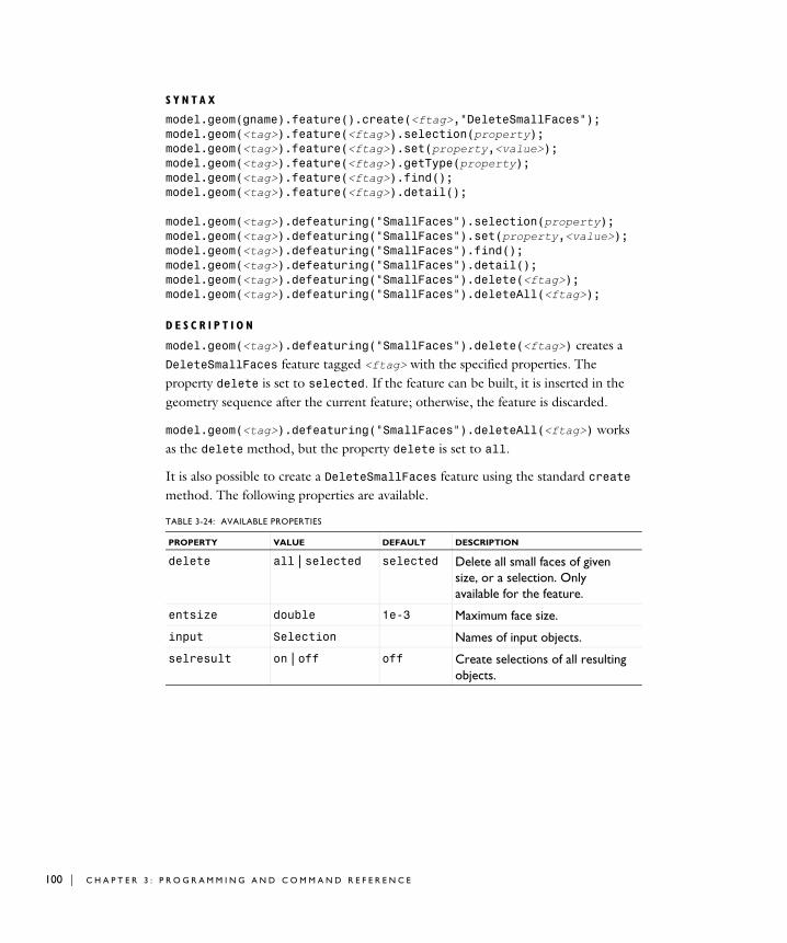
100 | C H A P T E
S Y N T A X
model.geom(gname).feature().create(<ftag>,"DeleteSmallFaces");model.geom(<tag>).feature(<ftag>).selection(property);model.geom(<tag>).feature(<ftag>).set(property,<value>);model.geom(<tag>).feature(<ftag>).getType(property);model.geom(<tag>).feature(<ftag>).find();model.geom(<tag>).feature(<ftag>).detail();
model.geom(<tag>).defeaturing("SmallFaces").selection(property);model.geom(<tag>).defeaturing("SmallFaces").set(property,<value>);model.geom(<tag>).defeaturing("SmallFaces").find();model.geom(<tag>).defeaturing("SmallFaces").detail();model.geom(<tag>).defeaturing("SmallFaces").delete(<ftag>);model.geom(<tag>).defeaturing("SmallFaces").deleteAll(<ftag>);
D E S C R I P T I O N
model.geom(<tag>).defeaturing("SmallFaces").delete(<ftag>) creates a DeleteSmallFaces feature tagged <ftag> with the specified properties. The property delete is set to selected. If the feature can be built, it is inserted in the geometry sequence after the current feature; otherwise, the feature is discarded.
model.geom(<tag>).defeaturing("SmallFaces").deleteAll(<ftag>) works as the delete method, but the property delete is set to all.
It is also possible to create a DeleteSmallFaces feature using the standard create method. The following properties are available.
TABLE 3-24: AVAILABLE PROPERTIES
PROPERTY VALUE DEFAULT DESCRIPTION
delete all | selected selected Delete all small faces of given size, or a selection. Only available for the feature.
entsize double 1e-3 Maximum face size.
input Selection Names of input objects.
selresult on | off off Create selections of all resulting objects.
R 3 : P R O G R A M M I N G A N D C O M M A N D R E F E R E N C E

A small face is a face that fits within a sphere of specified radius, given in the property entsize.
model.geom(<tag>).feature(<ftag>).find() searches the input objects for faces with size less than entsize.
model.geom(<tag>).feature(<ftag>).detail() returns a selection object where you can select a subset of the faces found.
The find and detail methods of model.geom(<tag>).defeaturing("SmallFaces") has the corresponding functionality for the defeaturing tool.
Only faces that can be deleted without invalidating the object are deleted. If a face was not possible to delete, a warning message is given, accessible through model.geom(<tag>).feature(<ftag>).problem().
C O M P A T I B I L I T Y
The following property is no longer supported:
E X A M P L E
The following example imports the geometry model from the file defeaturing_demo_6.x_b, finds sliver faces narrower than 10−3, and deletes the first of these.
Model model = ModelUtil.create("Model1");model.geom().create("geom1",3);model.geom("geom1").feature().create("imp1","Import");
selresultshow all | obj | dom | bnd | edg | pnt | off
dom Show selections of resulting objects in physics, materials, and so on, or in part instances. obj is not available in a component’s geometry. dom, bnd, and edg are not available in all features.
contributeto String none Tag of cumulative selection to contribute to.
TABLE 3-25: OBSOLETE PROPERTIES
PROPERTY VALUE DEFAULT DESCRIPTION
Out stx | ftx | ctx | ptx | status
none Output variables.
TABLE 3-24: AVAILABLE PROPERTIES
PROPERTY VALUE DEFAULT DESCRIPTION
C O M M A N D S I N A L P H A B E T I C A L O R D E R | 101

102 | C H A P T E
model.geom("geom1").feature("imp1").set("filename", "defeaturing_demo_6.x_b");model.geom("geom1").runAll();model.geom("geom1").feature().create("df1","DeleteSmallFaces");model.geom("geom1").feature("df1").selection("input"). set("imp1");model.geom("geom1").feature("df1").find();model.geom("geom1").feature("df1").detail().setGroup(1);model.geom("geom1").run();
S E E A L S O
DeleteFaces, DeleteSliverFaces
DeleteSpikes
Find and delete spikes in CAD objects.
S Y N T A X
model.geom(<tag>).feature().create(<ftag>,"DeleteSpikes");model.geom(<tag>).feature(<ftag>).selection(property);model.geom(<tag>).feature(<ftag>).set(property,<value>);model.geom(<tag>).feature(<ftag>).getType(property);model.geom(<tag>).feature(<ftag>).find();model.geom(<tag>).feature(<ftag>).detail();
model.geom(<tag>).defeaturing("Spikes").selection(property);model.geom(<tag>).defeaturing("Spikes").set(property,<value>);model.geom(<tag>).defeaturing("Spikes").find();model.geom(<tag>).defeaturing("Spikes").detail();model.geom(<tag>).defeaturing("Spikes").delete(<ftag>);model.geom(<tag>).defeaturing("Spikes").deleteAll(<ftag>);
D E S C R I P T I O N
model.geom(<tag>).defeaturing("DeleteSpikes").delete(<ftag>) creates a DeleteSpikes feature tagged <ftag> with the specified properties. The property delete is set to selected. If the feature can be built, it is inserted in the geometry sequence after the current feature; otherwise, the feature is discarded.
model.geom(<tag>).defeaturing("DeleteSpikes").deleteAll(<ftag>) works as the delete method, but the property delete is set to all.
R 3 : P R O G R A M M I N G A N D C O M M A N D R E F E R E N C E

It is also possible to create a DeleteSpikes feature using the standard create method. The following properties are available.
A spike is a long and narrow protrusion on an edge or corner of a face defined by two or three edges.
model.geom(<tag>).feature(<ftag>).find() searches the input objects for spikes of width less than entsize.
model.geom(<tag>).feature(<ftag>).detail() returns a selection object where you can select a subset of the spikes found.
The find and detail methods of model.geom(<tag>).defeaturing("Spikes") has the corresponding functionality for the defeaturing tool.
Only spikes that can be deleted without invalidating the object are deleted. If a spike was not possible to delete, a warning message is given, accessible through model.geom(<tag>).feature(<ftag>).problem().
C O M P A T I B I L I T Y
The width of each spike is no longer returned.
TABLE 3-26: AVAILABLE PROPERTIES
PROPERTY VALUE DEFAULT DESCRIPTION
delete all | selected selected Delete all spikes of given width, or a selection. Only available for the feature.
entsize double 1e-3 Maximum spike width.
input Selection Names of input objects.
selresult on | off off Create selections of all resulting objects.
selresultshow all | obj | dom | bnd | edg | pnt | off
dom Show selections of resulting objects in physics, materials, and so on, or in part instances. obj is not available in a component’s geometry. dom, bnd, and edg are not available in all features.
contributeto String none Tag of cumulative selection to contribute to.
C O M M A N D S I N A L P H A B E T I C A L O R D E R | 103
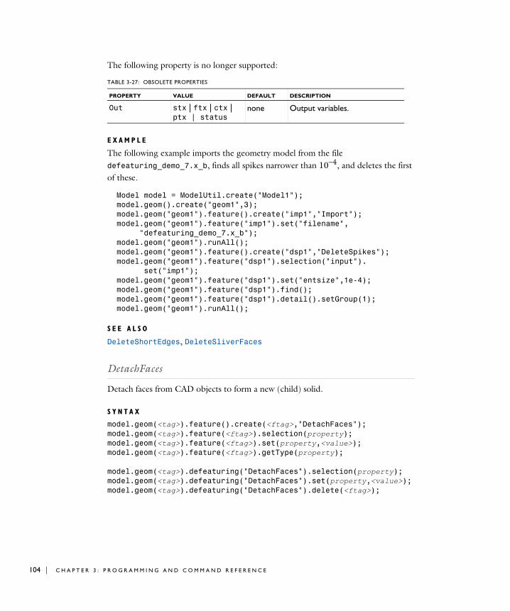
104 | C H A P T E
The following property is no longer supported:
E X A M P L E
The following example imports the geometry model from the file defeaturing_demo_7.x_b, finds all spikes narrower than 10−4, and deletes the first of these.
Model model = ModelUtil.create("Model1");model.geom().create("geom1",3);model.geom("geom1").feature().create("imp1","Import");model.geom("geom1").feature("imp1").set("filename", "defeaturing_demo_7.x_b");model.geom("geom1").runAll();model.geom("geom1").feature().create("dsp1","DeleteSpikes");model.geom("geom1").feature("dsp1").selection("input"). set("imp1");model.geom("geom1").feature("dsp1").set("entsize",1e-4);model.geom("geom1").feature("dsp1").find();model.geom("geom1").feature("dsp1").detail().setGroup(1);model.geom("geom1").runAll();
S E E A L S O
DeleteShortEdges, DeleteSliverFaces
DetachFaces
Detach faces from CAD objects to form a new (child) solid.
S Y N T A X
model.geom(<tag>).feature().create(<ftag>,"DetachFaces");model.geom(<tag>).feature(<ftag>).selection(property);model.geom(<tag>).feature(<ftag>).set(property,<value>);model.geom(<tag>).feature(<ftag>).getType(property);
model.geom(<tag>).defeaturing("DetachFaces").selection(property);model.geom(<tag>).defeaturing("DetachFaces").set(property,<value>);model.geom(<tag>).defeaturing("DetachFaces").delete(<ftag>);
TABLE 3-27: OBSOLETE PROPERTIES
PROPERTY VALUE DEFAULT DESCRIPTION
Out stx | ftx | ctx | ptx | status
none Output variables.
R 3 : P R O G R A M M I N G A N D C O M M A N D R E F E R E N C E

D E S C R I P T I O N
model.geom(<tag>).defeaturing("DetachFaces").delete(<ftag>) creates a DetachFaces feature tagged <ftag> with the specified properties. If the feature can be built, it is inserted in the geometry sequence after the current feature; otherwise, the feature is discarded.
It is also possible to create a DetachFaces feature using the standard create method.
The faces in the property input are detached from their parent object. A new solid, the child object, are formed from the detached faces. The output objects are the healed parent and child objects.
The property healparent determines how the parent object is healed to form a new solid after detaching the faces. The value fill means that a new face is formed based on the surrounding edges of each wound. The value patch means that the surrounding faces of each wound are grown or shrunk.
The property healchild determines how the child solid is constructed from the detached faces. The value fill means that a new face is formed based on the surrounding edges of each wound. The value patchchild means that the detached faces are grown or shrunk to form a solid. The value patchparent means that the
TABLE 3-28: AVAILABLE PROPERTIES
PROPERTY VALUE DEFAULT DESCRIPTION
input Selection Faces to detach.
healchild fill | patchchild | patchparent
patchparent Healing method used on the child object.
healparent fill | patch patch Healing method used on the parent object.
selresult on | off off Create selections of all resulting objects.
selresultshow all | obj | dom | bnd | edg | pnt | off
dom Show selections of resulting objects in physics, materials, and so on, or in part instances. obj is not available in a component’s geometry. dom, bnd, and edg are not available in all features.
contributeto String none Tag of cumulative selection to contribute to.
C O M M A N D S I N A L P H A B E T I C A L O R D E R | 105

106 | C H A P T E
parent faces surrounding the detached faces are grown or shrunk to form a solid together with the detached faces.
E X A M P L E
The following example imports the COMSOL Multiphysics geometry file defeaturing_demo_2.mphbin and detaches a hole defined by a set of faces:
Model model = ModelUtil.create("Model1");model.geom().create("geom1",3);model.geom("geom1").feature().create("imp1","Import");model.geom("geom1").feature("imp1").set("filename", "defeaturing_demo_2.mphbin");model.geom("geom1").runAll();model.geom("geom1").feature().create("det1","DetachFaces");model.geom("geom1").feature("det1").selection("input"). set("imp1",6,7,8,9,11,12,13);model.geom("geom1").runAll();
C O M P A T I B I L I T Y
The following property is no longer supported:
S E E A L S O
DeleteFaces
DirectedDistance
P U R P O S E
Constrain the distance in a given direction between two geometric entities to a given value.
TABLE 3-29: OBSOLETE PROPERTIES
PROPERTY VALUE DEFAULT DESCRIPTION
Out stx | ftx | ctx | ptx
none Output variables
R 3 : P R O G R A M M I N G A N D C O M M A N D R E F E R E N C E

D E S C R I P T I O N
S E E A L S O
Distance, XDistance, YDistance
Distance
P U R P O S E
Constrain the distance between two geometric entities to a given value.
TABLE 3-30: AVAILABLE PROPERTIES
PROPERTY VALUE DEFAULT DESCRIPTION
entity1 Selection First entity (vertex or curved edge)
entity2 Selection Second entity (vertex or curved edge)
direction vector | parallel | perpendicular
vector Direction
vector double[2] {1, 0} Direction vector (used when direction is vector)
edge Selection Straight edge determining the direction (used when direction is parallel or perpendicular)
distance double 0 Distance
helppoint1 double[2] {0, 0} First help point
helppoint2 double[2] {0, 0} Second help point
arrowdispl double NaN Displacement of arrow symbol in the normal direction
labelpos double 0.5 Relative label position along arrow symbol
arrowint on | off on Internal or external arrow symbol
C O M M A N D S I N A L P H A B E T I C A L O R D E R | 107

108 | C H A P T E
D E S C R I P T I O N
S E E A L S O
DirectedDistance, XDistance, YDistance, EqualDistance, TotalEdgeLength
Ellipse
The following additional properties are available with the Design Module.
TABLE 3-31: AVAILABLE PROPERTIES
PROPERTY VALUE DEFAULT DESCRIPTION
entity1 Selection First entity (vertex or edge)
entity2 Selection Second entity (vertex or edge)
distance double 0 Distance
helppoint1 double[2] {0, 0} First help point
helppoint2 double[2] {0, 0} Second help point
arrowdispl double NaN Displacement of arrow symbol in the normal direction
labelpos double 0.5 Relative label position along arrow symbol
arrowint on | off on Internal or external arrow symbol
TABLE 3-32: AVAILABLE PROPERTIES
PROPERTY VALUE DEFAULT DESCRIPTION
semiaxesconstr String[2] {off, off} Constrain the semiaxes. Constrained properties cannot be modified by constraint and dimension functions.
angleconstr on | off on Constrain the sector angle. Constrained properties cannot be modified by constraint and dimension functions.
R 3 : P R O G R A M M I N G A N D C O M M A N D R E F E R E N C E

EqualDistance
P U R P O S E
Constrain the distances between two pairs of geometric entities to be equal.
posconstr String[2] {off, off} Constrain the position. Constrained properties cannot be modified by constraint and dimension functions.
rotconstr on | off on Constrain the rotation angle. Constrained properties cannot be modified by constraint and dimension functions.
TABLE 3-32: AVAILABLE PROPERTIES
PROPERTY VALUE DEFAULT DESCRIPTION
C O M M A N D S I N A L P H A B E T I C A L O R D E R | 109

110 | C H A P T E
D E S C R I P T I O N
S E E A L S O
Distance
EqualRadius
P U R P O S E
Constrain two circular edges to have the same radius.
TABLE 3-33: AVAILABLE PROPERTIES
PROPERTY VALUE DEFAULT DESCRIPTION
entity1 Selection First entity (vertex or edge)
entity2 Selection Second entity (vertex or edge)
entity3 Selection Third entity (vertex or edge)
entity4 Selection Fourth entity (vertex or edge)
helppoint1 double[2] {0, 0} First help point
helppoint2 double[2] {0, 0} Second help point
helppoint3 double[2] {0, 0} Third help point
helppoint4 double[2] {0, 0} Fourth help point
arrowdispl double[2] NaN Displacement of arrow symbols in the normal direction
labelpos double[2] {0.5, 0.5} Relative label position along arrow symbols
arrowint String[2] {on, on} Internal or external arrow symbols
label String Label text
R 3 : P R O G R A M M I N G A N D C O M M A N D R E F E R E N C E

D E S C R I P T I O N
S E E A L S O
Radius
Export, ExportFinal
Using the CAD Import Module, Design Module, or a LiveLink product for CAD software, export selected geometry objects or the finalized geometry to a 3D CAD format, such as ACIS, Parasolid, STEP, and IGES.
To export selected geometry objects to a file, first select the objects to export using
model.component(<ctag>).geom(<tag>).export().selection().set(<objnames>);
where <objnames> is a string array of object names. Then export them by entering
model.component(<ctag>).geom(<tag>).export(<filename>);
To export the finalized geometry to a file, enter
model.component(<ctag>).geom(<tag>).exportFinal(<filename>);
where <filename> is a string.
In the above commands the file extension in the <filename> string determines the file format, which can be of any of the following:
TABLE 3-34: AVAILABLE PROPERTIES
PROPERTY VALUE DEFAULT DESCRIPTION
edge1 Selection First circular edge
edge2 Selection Second circular edge
arrowangdispl double[2] {0, 0} Angular displacement of arrow symbols relative to middle of edges
labelradius double[2] {0.5, 0.5} Relative label position along arrow symbols
label String Label text
TABLE 3-35: SUPPORTED FILE FORMATS
FILE FORMAT FILE EXTENSION
Parasolid Binary (3D) .x_b, .xmt_bin
Parasolid Text (3D) .x_t, .xmt_txt
C O M M A N D S I N A L P H A B E T I C A L O R D E R | 111

112 | C H A P T E
E X P O R T I N G T O A N A C I S F I L E
When exporting to an ACIS file you can set the ACIS file format version using
model.component(<ctag>).geom(<tag>).export().setAcisVersion(<version>);
where <version> is a string 4.0, 7.0, or 2016 1.0. Default is 2016 1.0.
E X P O R T I N G T O A P A R A S O L I D F I L E
The Parasolid text or binary file generated by the export is of version 31.0.
When exporting to a Parasolid format, a unit conversion can optionally be performed during export. Use the following method to select the export length unit:
model.component(<ctag>).geom(<tag>).export().setLengthUnit(<unit>);
where <unit> is either fromgeom (default) to disable unit conversion or a COMSOL Multiphysics length unit, such as m for meters or in for inches. To get the current value of the export length unit type:
model.component(<ctag>).geom(<tag>).export().getLengthUnit();
To decide how the non-manifold objects are exported use the following method:
model.component(<ctag>).geom(<tag>).export().setSplitInManifold(<value>);
where <value> is either true (default) to split the objects into manifold objects during the export, or false to export the unmodified objects.
E X P O R T I N G T O A N I G E S F I L E
When exporting to the IGES format, a unit conversion can optionally be performed during export. Use the following method to select the export length unit:
model.component(<ctag>).geom(<tag>).export().setLengthUnitIGES(<unit>);
ACIS Binary (3D) .sab
ACIS Text (3D) .sat
IGES File (3D) .igs, .iges
STEP File (3D) .step, .stp
TABLE 3-35: SUPPORTED FILE FORMATS
FILE FORMAT FILE EXTENSION
R 3 : P R O G R A M M I N G A N D C O M M A N D R E F E R E N C E

where <unit> is either fromgeom (default) to disable unit conversion or a supported
length unit: uin, um, mil, mm, cm, in, ft, m, km, mi.To get the current value of the export length unit type:
model.component(<ctag>).geom(<tag>).export().getLengthUnitIGES();
E X P O R T I N G T O A S T E P F I L E
When exporting to the STEP format, a unit conversion can optionally be performed during export. Use the following method to select the export length unit:
model.component(<ctag>).geom(<tag>).export().setLengthUnitSTEP(<unit>);
where <unit> is either fromgeom (default) to disable unit conversion or a supported
length unit: nm, uin, um, mil, mm, cm, in, dm, ft, m, km, mi. To get the current value of the export length unit type:
model.component(<ctag>).geom(<tag>).export().getLengthUnitSTEP();
S E E A L S O
Import
Fillet
The following additional properties are available with the Design Module.
Fillet3D
Fillet edges in 3D geometry objects.
S Y N T A X
model.geom(<tag>).feature().create(<ftag>,"Fillet3D");model.geom(<tag>).feature(<ftag>).selection(property);model.geom(<tag>).feature(<ftag>).set(property,<value>);model.geom(<tag>).feature(<ftag>).getType(property);
D E S C R I P T I O N
model.geom(<tag>).feature().create(<ftag>,"Fillet3D")
TABLE 3-36: AVAILABLE PROPERTIES
PROPERTY VALUE DEFAULT DESCRIPTION
radiusconstr on | off off Constrain the radius. Constrained properties cannot be modified by constraint and dimension functions.
C O M M A N D S I N A L P H A B E T I C A L O R D E R | 113
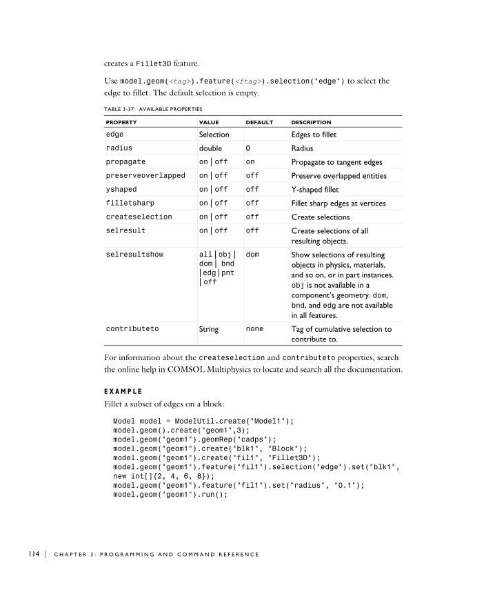
114 | C H A P T E
creates a Fillet3D feature.
Use model.geom(<tag>).feature(<ftag>).selection("edge") to select the edge to fillet. The default selection is empty.
For information about the createselection and contributeto properties, search the online help in COMSOL Multiphysics to locate and search all the documentation.
E X A M P L E
Fillet a subset of edges on a block:
Model model = ModelUtil.create("Model1");model.geom().create("geom1",3);model.geom("geom1").geomRep("cadps");model.geom("geom1").create("blk1", "Block");model.geom("geom1").create("fil1", "Fillet3D");model.geom("geom1").feature("fil1").selection("edge").set("blk1", new int[]{2, 4, 6, 8});model.geom("geom1").feature("fil1").set("radius", "0.1");model.geom("geom1").run();
TABLE 3-37: AVAILABLE PROPERTIES
PROPERTY VALUE DEFAULT DESCRIPTION
edge Selection Edges to fillet
radius double 0 Radius
propagate on | off on Propagate to tangent edges
preserveoverlapped on | off off Preserve overlapped entities
yshaped on | off off Y-shaped fillet
filletsharp on | off off Fillet sharp edges at vertices
createselection on | off off Create selections
selresult on | off off Create selections of all resulting objects.
selresultshow all | obj | dom | bnd | edg | pnt | off
dom Show selections of resulting objects in physics, materials, and so on, or in part instances. obj is not available in a component’s geometry. dom, bnd, and edg are not available in all features.
contributeto String none Tag of cumulative selection to contribute to.
R 3 : P R O G R A M M I N G A N D C O M M A N D R E F E R E N C E

S E E A L S O
Chamfer3D
Import
Import geometry objects from a 3D CAD file using the CAD Import Module, Design Module, or a LiveLink product for CAD software.
S Y N T A X
model.geom(<tag>).feature().create(<ftag>,"Import");model.geom(<tag>).feature(<ftag>).set(property,<value>);model.geom(<tag>).feature(<ftag>).getType(property);model.geom(<tag>).feature(<ftag>).importData();
D E S C R I P T I O N
model.geom(<tag>).feature().create(<ftag>,"Import") creates an import feature. When the property filename is set to a filename recognized as a 3D CAD file, the property type is set to cad. The following properties are available.
TABLE 3-38: AVAILABLE PROPERTIES
PROPERTY VALUE DEFAULT DESCRIPTION
check on | off Check imported objects for errors.
filename String Filename.
fillholes on | off off Attempt to generate new faces to replace missing geometry if the property knit is solid or surface
importtol double 1e-5 Absolute repair tolerance.
keepbnd on | off on Import surface objects.
keepfree on | off off Import curve and point objects.
keepsolid on | off on Import solid objects.
knit solid | surface | off
solid Knit together surface objects to form solids or surface objects.
removeredundant on | off off Remove redundant edges and vertices.
repair on | off on Repair imported objects.
type cad Type of import.
C O M M A N D S I N A L P H A B E T I C A L O R D E R | 115

116 | C H A P T E
The file to import is specified by filename, which can have of any of the following formats:
Note 1: This format requires a license for the CAD Import Module, Design Module, or a LiveLink product for a CAD package.
Note 2: This format requires, in addition to the CAD Import Module, Design Module, or a LiveLink product for a CAD package, a license for the File Import for CATIA V5 module.
Note 3: Only supported on Windows.
unit source | current source Take length unit from file or from the current geometry unit.
unitecurves on | off on Unite curve objects.
selresult on | off off Create selections of all resulting objects.
selresultshow all | obj | dom | bnd | edg | pnt | off
dom Show selections of resulting objects in physics, materials, and so on, or in part instances. obj is not available in a component’s geometry. dom, bnd, and edg are not available in all features.
contributeto String none Tag of cumulative selection to contribute to.
TABLE 3-39: SUPPORTED 3D CAD FILE FORMATS
FILE FORMAT NOTE FILE EXTENSION
Autodesk Inventor 1, 3 .ipt, .iam
CATIA V5 2, 3 .CATPart, .CATProduct
IGES 1 .igs, .iges
Parasolid 1 .x_t, .x_b
PTC Pro/ENGINEER 1 .prt, .asm
SAT (ACIS) 1 .sat, .sab
SOLIDWORKS 1, 3 .sldprt, .sldasm
STEP 1 .step, .stp
TABLE 3-38: AVAILABLE PROPERTIES
PROPERTY VALUE DEFAULT DESCRIPTION
R 3 : P R O G R A M M I N G A N D C O M M A N D R E F E R E N C E

The imported geometry objects are represented using the Parasolid geometry kernel, which is the geometry kernel utilized by the CAD Import Module and the LiveLink products for CAD software.
The method
model.geom(gname).feature(<ftag>).importData()
imports the file again, even if the feature is built.
The import can generate object, boundary, edge, and point selections based on material, layer, and color assignments in the 3D CAD file. The following properties are available for working these selections:
TABLE 3-40: AVAILABLE PROPERTIES
PROPERTY VALUE DEFAULT DESCRIPTION
selcadshownamesfromfileobj boolean false Show the object selection names from the file in the GUI.
selcadnameobj String[] empty Names of object selections in 3D CAD import.
selcadnameinfileobj String[] empty Original names of object selections in 3D CAD import. Read-only.
selcadkeepobj on | off empty Keep object selections in 3D CAD import.
selcadshowobj on | off empty Show object selections in 3D CAD import in physics, materials, and so on; in part instances; or in 3D from a plane geometry.
selcadcontributetoobj String[] empty Tags of cumulative selection to contribute to (or none to not contribute), for object selections in 3D CAD import.
selcadtagobj String[] empty Tags of object selections (read-only, hidden in GUI) in 3D CAD import.
C O M M A N D S I N A L P H A B E T I C A L O R D E R | 117

118 | C H A P T E
selcadcolorobj String[] empty Colors of object selections (read-only) in 3D CAD import. The color is stored as a comma-separated triple of numbers between 0 and 1. It can also be "none" (in which case it will be displayed in yellow).
selindividualintable boolean false Show individual object selections and, for the knit case, individual original object selections in the CAD-tables.
selcadshownamesfromfilebnd boolean false Show the boundary selection names from the file in the GUI.
selcadnamebnd String[] empty Names of boundary selections in 3D CAD import.
selcadnameinfilebnd String[] empty Original names of boundary selections in 3D CAD import. Read-only.
selcadkeepbnd on | off empty Keep boundary selections in 3D CAD import.
selcadshowbnd on | off empty Show boundary selections in 3D CAD import in physics, materials, and so on; in part instances; or in 3D from a plane geometry.
selcadcontributetobnd String[] empty Tags of cumulative selection to contribute to (or none to not contribute), for boundary selections in 3D CAD import.
TABLE 3-40: AVAILABLE PROPERTIES
PROPERTY VALUE DEFAULT DESCRIPTION
R 3 : P R O G R A M M I N G A N D C O M M A N D R E F E R E N C E

selcadtagbnd String[] empty Tags of boundary selections (read-only, hidden in GUI) in 3D CAD import.
selcadcolorbnd String[] empty Colors of boundary selections (read-only) in 3D CAD import. The color is stored as a comma-separated triple of numbers between 0 and 1. It can also be "none" (in which case it will be displayed in yellow).
selcadshownamesfromfileedg boolean false Show the edge selection names from the file in the GUI.
selcadnameedg String[] empty Names of edge selections in 3D CAD import.
selcadnameinfileedg String[] empty Original names of edge selections in 3D CAD import. Read-only.
selcadkeepedg on | off empty Keep edge selections in 3D CAD import.
selcadshowedg on | off empty Show edge selections in 3D CAD import in physics, materials, and so on; in part instances; or in 3D from a plane geometry.
selcadcontributetoedg String[] empty Tags of cumulative selection to contribute to (or none to not contribute), for edge selections in 3D CAD import.
selcadtagedg String[] empty Tags of edge selections (read-only, hidden in GUI) in 3D CAD import.
TABLE 3-40: AVAILABLE PROPERTIES
PROPERTY VALUE DEFAULT DESCRIPTION
C O M M A N D S I N A L P H A B E T I C A L O R D E R | 119

120 | C H A P T E
selcadcoloredg String[] empty Colors of edge selections (read-only) in 3D CAD import. The color is stored as a comma-separated triple of numbers between 0 and 1. It can also be "none" (in which case it will be displayed in yellow).
selcadshownamesfromfilepnt boolean false Show the point selection names from the file in the GUI.
selcadnamepnt String[] empty Names of point selections in 3D CAD import.
selcadnameinfilepnt String[] empty Original names of point selections in 3D CAD import. Read-only.
selcadkeeppnt on | off empty Keep point selections in 3D CAD import.
selcadshowpnt on | off empty Show point selections in 3D CAD import in physics, materials, and so on; in part instances; or in 3D from a plane geometry.
selcadcontributetopnt String[] empty Tags of cumulative selection to contribute to (or none to not contribute), for point selections in 3D CAD import.
TABLE 3-40: AVAILABLE PROPERTIES
PROPERTY VALUE DEFAULT DESCRIPTION
R 3 : P R O G R A M M I N G A N D C O M M A N D R E F E R E N C E

C O M P A T I B I L I T Y
The following property is no longer supported:
S E E A L S O
Export, ExportFinal
InterpolationCurve
The following additional properties are available with the Design Module.
selcadtagpnt String[] empty Tags of point selections (read-only, hidden in GUI) in 3D CAD import.
selcadcolorpnt String[] empty Colors of point selections (read-only) in 3D CAD import. The color is stored as a comma-separated triple of numbers between 0 and 1. It can also be "none" (in which case it will be displayed in yellow).
TABLE 3-41: OBSOLETE PROPERTIES
PROPERTY VALUE DEFAULT DESCRIPTION
coercion solid | face | off
solid Alias for knit. face is equivalent to surface.
TABLE 3-42: AVAILABLE PROPERTIES
PROPERTY VALUE DEFAULT DESCRIPTION
tableconstr String[] {} Constrain the interpolation points. Constrained properties cannot be modified by constraint and dimension functions.
TABLE 3-40: AVAILABLE PROPERTIES
PROPERTY VALUE DEFAULT DESCRIPTION
C O M M A N D S I N A L P H A B E T I C A L O R D E R | 121

122 | C H A P T E
Knit
Knit surface CAD objects to form solids or surface objects.
S Y N T A X
model.geom(<tag>).feature().create(<ftag>,"Knit");model.geom(<tag>).feature(<ftag>).selection(property);model.geom(<tag>).feature(<ftag>).set(property,<value>);model.geom(<tag>).feature(<ftag>).getType(property)
D E S C R I P T I O N
model.geom(<ftag>).feature().create(<ftag>,"Knit") creates a knit feature tagged <ftag>. The following properties are available.
starttangconstr String[2] {off, off} Constrain the start tangent. Constrained properties cannot be modified by constraint and dimension functions.
endtangconstr String[2] {off, off} Constrain the end tangent. Constrained properties cannot be modified by constraint and dimension functions.
TABLE 3-43: AVAILABLE PROPERTIES
PROPERTY VALUE DEFAULT DESCRIPTION
fillholes on | off off Attempt to generate new faces to replace missing geometry
input Selection Names of input surface objects.
repairtol double 1e-5 Absolute repair tolerance.
selresult on | off off Create selections of all resulting objects.
selresultshow all | obj | dom | bnd | edg | pnt | off
dom Show selections of resulting objects in physics, materials, and so on, or in part instances. obj is not available in a component’s geometry. dom, bnd, and edg are not available in all features.
contributeto String none Tag of cumulative selection to contribute to.
TABLE 3-42: AVAILABLE PROPERTIES
PROPERTY VALUE DEFAULT DESCRIPTION
R 3 : P R O G R A M M I N G A N D C O M M A N D R E F E R E N C E

This function also removes gaps and spikes that are within the absolute tolerance specified in the property repairtol.
C O M P A T I B I L I T Y
The following property is no longer supported:
E X A M P L E
The following example imports the file repair_demo_2.x_b, and knits the surface objects into a solid. A gap is also removed during the operation.
Model model = ModelUtil.create("Model1");model.geom().create("geom1",3);model.geom("geom1").feature().create("imp1","Import");model.geom("geom1").feature("imp1").set("filename", "repair_demo_2.x_b");model.geom("geom1").runAll();model.geom("geom1").feature().create("knit1","Knit");model.geom("geom1").feature("knit1").selection("input"). set("imp1");model.geom("geom1").feature("knit1").set("repairtol",1e-3);model.geom("geom1").runAll();
S E E A L S O
Repair
LineSegment
The following additional properties are available with the Design Module.
TABLE 3-44: OBSOLETE PROPERTIES
PROPERTY VALUE DEFAULT DESCRIPTION
Out stx | ftx | ctx | ptx
none Output variables.
TABLE 3-45: AVAILABLE PROPERTIES
PROPERTY VALUE DEFAULT DESCRIPTION
coord1constr String[2] {off, off} Constrain the coordinates of the starting point. Constrained properties cannot be modified by constraint and dimension functions.
coord2constr String[2] {off, off} Constrain the coordinates of the endpoint. Constrained properties cannot be modified by constraint and dimension functions.
C O M M A N D S I N A L P H A B E T I C A L O R D E R | 123

124 | C H A P T E
Loft
Create a lofted surface through a set of profile curves.
S Y N T A X
model.geom(<tag>).feature().create(<ftag>,"Loft");model.geom(<tag>).feature(<ftag>).selection(property);model.geom(<tag>).feature(<ftag>).set(property,<value>);model.geom(<tag>).feature(<ftag>).getType(property);
D E S C R I P T I O N
model.geom(<tag>).feature().create(<ftag>,"Loft")
creates a Loft feature.
Use model.geom(<tag>).feature(<ftag>).selection("profile") to select loft profiles that are not specified as start or end profiles. The default selection is empty.
Use model.geom(<tag>).feature(<ftag>).selection("startprofile") to select the loft start profile. The default selection is empty.
Use model.geom(<tag>).feature(<ftag>).selection("endprofile") to select the loft start profile. The default selection is empty.
Use model.geom(<tag>).feature(<ftag>).selection("guide") to select guide curves that are not specified as start or end guide curves. The default selection is empty.
Use model.geom(<tag>).feature(<ftag>).selection("startguide") to select the start guide curve. The default selection is empty.
Use model.geom(<tag>).feature(<ftag>).selection("endguide") to select the end guide curve. The default selection is empty.
TABLE 3-46: AVAILABLE PROPERTIES
PROPERTY VALUE DEFAULT DESCRIPTION
periodic on | off off Periodic loft.
unite on | off on Unite with input objects.
crossfaces on | off off Keep intermediate profile faces.
type solid | surface solid Object type.
facepartioning minimal | columns | grid
minimal Face partitioning.
profile Selection Profiles.
startprofile Selection Start profile selection.
R 3 : P R O G R A M M I N G A N D C O M M A N D R E F E R E N C E

For information about the createselection and contributeto properties, search the online help in COMSOL Multiphysics to locate and search the documentation.
startprofiledir notprescribed | parallel | perpendicular | atangle
notprescribed
Loft direction.
startprofilerel profilefaces | adjacent | profileedges
adjacent Relative to.
startprofileangle double 0 Angle.
endprofile Selection End profile selection.
endprofiledir notprescribed | parallel | perpendicular | atangle
notprescribed
Loft direction.
endprofilerel profilefaces | adjacent | profileedges
adjacent Relative to.
endprofileangle double 0 Angle.
guide Selection Guide curves.
startguide Selection Start guide curve.
startguidedir notprescribed | parallel
notprescribed
Loft surface direction.
endguide Selection Start guide curve.
endguidedir notprescribed | parallel
notprescribed
Loft surface direction.
selresult on | off off Create selections of all resulting objects.
selresultshow all | obj | dom | bnd | edg | pnt | off
dom Show selections of resulting objects in physics, materials, and so on, or in part instances. obj is not available in a component’s geometry. dom, bnd, and edg are not available in all features.
contributeto String none Tag of cumulative selection to contribute to.
TABLE 3-46: AVAILABLE PROPERTIES
PROPERTY VALUE DEFAULT DESCRIPTION
C O M M A N D S I N A L P H A B E T I C A L O R D E R | 125

126 | C H A P T E
E X A M P L E
Create a cylinder from two disc profiles. This illustrates two different ways of specifying the profile.
Model model = ModelUtil.create("Model1");model.geom().create("geom1", 3);model.geom("geom1").geomRep("cadps");model.geom("geom1").feature().create("wp1", "WorkPlane");model.geom("geom1").feature("wp1").geom().create("c1", "Circle");model.geom("geom1").create("copy1", "Copy");model.geom("geom1").feature("copy1").selection("input").set(new String[]{"wp1"});model.geom("geom1").feature("copy1").set("displz", "1");model.geom("geom1").create("loft1", "Loft");model.geom("geom1").feature("loft1").selection("profile").set(new String[]{"wp1"});model.geom("geom1").feature("loft1").selection("startprofile").init(1);model.geom("geom1").feature("loft1").selection("startprofile").set("copy1", new int[]{1, 2, 3, 4});model.geom("geom1").run();
Midsurface
Generate a surface object that is the midsurface of a solid object in 3D.
S Y N T A X
model.geom(<tag>).feature().create(<ftag>,"Midsurface");model.geom(<tag>).feature(<ftag>).selection(property);model.geom(<tag>).feature(<ftag>).set(property,<value>);model.geom(<tag>).feature(<ftag>).getType(property);
D E S C R I P T I O N
model.geom(<tag>).feature().create(<ftag>,"Midsurface")
creates a Midsurface feature.
Use model.geom(<tag>).feature(<ftag>).selection("input") to select the objects for the midsurface operation. The default selection is empty.
TABLE 3-47: AVAILABLE PROPERTIES
PROPERTY VALUE DEFAULT DESCRIPTION
repair on | off on Repair overlaps
split on | off off Split in smooth components
createselection on | off off Create selections
contributeto String none Cumulative selection to contribute to
R 3 : P R O G R A M M I N G A N D C O M M A N D R E F E R E N C E

For information about the createselection and contributeto properties, search the online help in COMSOL Multiphysics to locate and search all the documentation.
E X A M P L E
Generate the midsurface of a thin block:
Model model = ModelUtil.create("Model1");model.geom().create("geom1", 3);model.geom("geom1").geomRep("cadps");model.geom("geom1").create("blk1", "Block");model.geom("geom1").feature("blk1").set("size", new String[]{"1", "1", "0.1"});model.geom("geom1").create("mid1", "Midsurface");model.geom("geom1").feature("mid1").selection("input").set(new String[]{"blk1"});model.geom("geom1").run();
S E E A L S O
Thicken
Mirror
The following additional properties are available with the Design Module.
TABLE 3-48: AVAILABLE PROPERTIES
PROPERTY VALUE DEFAULT DESCRIPTION
posconstr String[2] {on, on} Constrain point on line of reflection. Constrained properties cannot be modified by constraint and dimension functions.
axisconstr String[2] {on, on} Constrain normal vector to line of reflection. Constrained properties cannot be modified by constraint and dimension functions.
C O M M A N D S I N A L P H A B E T I C A L O R D E R | 127

128 | C H A P T E
Move
The following additional properties are available with the Design Module.
Parallel
P U R P O S E
Constrains straight edges to be parallel.
D E S C R I P T I O N
S E E A L S O
Angle
Perpendicular
P U R P O S E
Constrains two straight edges to be orthogonal.
TABLE 3-49: AVAILABLE PROPERTIES
PROPERTY VALUE DEFAULT DESCRIPTION
displxconstr on | off on Constrain the x-displacement. Constrained properties cannot be modified by constraint and dimension functions.
displyconstr on | off on Constrain the y-displacement. Constrained properties cannot be modified by constraint and dimension functions.
TABLE 3-50: AVAILABLE PROPERTIES
PROPERTY VALUE DEFAULT DESCRIPTION
edge Selection Straight edges
symboledg Selection Edge the symbol in the Graphics window is attached to
symboledgpar double 0.5 Normalized edge parameter for positioning the symbol
symboledgdispl double 20 Symbol displacement in left normal direction from edge (in pixels)
R 3 : P R O G R A M M I N G A N D C O M M A N D R E F E R E N C E
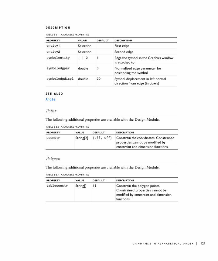
D E S C R I P T I O N
S E E A L S O
Angle
Point
The following additional properties are available with the Design Module.
Polygon
The following additional properties are available with the Design Module.
TABLE 3-51: AVAILABLE PROPERTIES
PROPERTY VALUE DEFAULT DESCRIPTION
entity1 Selection First edge
entity2 Selection Second edge
symbolentity 1 | 2 1 Edge the symbol in the Graphics window is attached to
symboledgpar double 0 Normalized edge parameter for positioning the symbol
symboledgdispl double 20 Symbol displacement in left normal direction from edge (in pixels)
TABLE 3-52: AVAILABLE PROPERTIES
PROPERTY VALUE DEFAULT DESCRIPTION
pconstr String[2] {off, off} Constrain the coordinates. Constrained properties cannot be modified by constraint and dimension functions.
TABLE 3-53: AVAILABLE PROPERTIES
PROPERTY VALUE DEFAULT DESCRIPTION
tableconstr String[] {} Constrain the polygon points. Constrained properties cannot be modified by constraint and dimension functions.
C O M M A N D S I N A L P H A B E T I C A L O R D E R | 129

130 | C H A P T E
Position
P U R P O S E
Constrain a vertex to have given coordinates.
D E S C R I P T I O N
QuadraticBezier
The following additional properties are available with the Design Module.
Radius
P U R P O S E
Constrain a circular edge to have a given radius.
TABLE 3-54: AVAILABLE PROPERTIES
PROPERTY VALUE DEFAULT DESCRIPTION
vertex Selection Vertex to fix
pos double[2] {0, 0} Coordinates
symbolvtxdispl double[2] {20, 20} Displacement of the symbol in the Graphics window from the vertex (in pixels)
TABLE 3-55: AVAILABLE PROPERTIES
PROPERTY VALUE DEFAULT DESCRIPTION
pconstr String[3] {off, off, off}
Constrain the control points. Constrained properties cannot be modified by constraint and dimension functions.
R 3 : P R O G R A M M I N G A N D C O M M A N D R E F E R E N C E

D E S C R I P T I O N
S E E A L S O
EqualRadius
Rectangle
The following additional properties are available with the Design Module.
Repair
Repair CAD objects.
TABLE 3-56: AVAILABLE PROPERTIES
PROPERTY VALUE DEFAULT DESCRIPTION
edge Selection Circular edge
radius double 0 Radius
arrowangdispl double 0 Angular displacement of arrow symbol relative to middle of edge
labelradius double 0.5 Relative label position along arrow symbol
TABLE 3-57: AVAILABLE PROPERTIES
PROPERTY VALUE DEFAULT DESCRIPTION
sizeconstr String[2] {off, off} Constrain the width and the height. Constrained properties cannot be modified by constraint and dimension functions.
posconstr String[2] {off, off} Constrain the position. Constrained properties cannot be modified by constraint and dimension functions.
rotconstr on | off off Constrain the rotation angle. Constrained properties cannot be modified by constraint and dimension functions.
arrowdispl double[2] NaN Displacement of arrow symbols in the normal direction.
labelpos double[2] {0.5, 0.5} Relative label position along arrow symbols.
arrowint String[2] {on, on} Internal or external arrow symbols.
C O M M A N D S I N A L P H A B E T I C A L O R D E R | 131
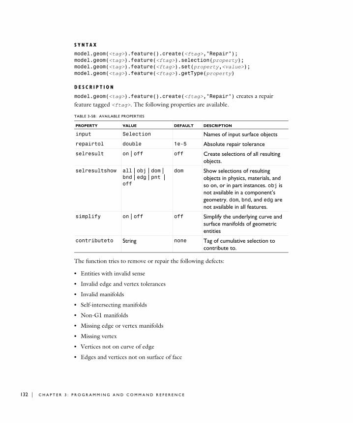
132 | C H A P T E
S Y N T A X
model.geom(<tag>).feature().create(<ftag>,"Repair");model.geom(<tag>).feature(<ftag>).selection(property);model.geom(<tag>).feature(<ftag>).set(property,<value>);model.geom(<tag>).feature(<ftag>).getType(property)
D E S C R I P T I O N
model.geom(<tag>).feature().create(<ftag>,"Repair") creates a repair feature tagged <ftag>. The following properties are available.
The function tries to remove or repair the following defects:
• Entities with invalid sense
• Invalid edge and vertex tolerances
• Invalid manifolds
• Self-intersecting manifolds
• Non-G1 manifolds
• Missing edge or vertex manifolds
• Missing vertex
• Vertices not on curve of edge
• Edges and vertices not on surface of face
TABLE 3-58: AVAILABLE PROPERTIES
PROPERTY VALUE DEFAULT DESCRIPTION
input Selection Names of input surface objects
repairtol double 1e-5 Absolute repair tolerance
selresult on | off off Create selections of all resulting objects.
selresultshow all | obj | dom | bnd | edg | pnt | off
dom Show selections of resulting objects in physics, materials, and so on, or in part instances. obj is not available in a component’s geometry. dom, bnd, and edg are not available in all features.
simplify on | off off Simplify the underlying curve and surface manifolds of geometric entities
contributeto String none Tag of cumulative selection to contribute to.
R 3 : P R O G R A M M I N G A N D C O M M A N D R E F E R E N C E
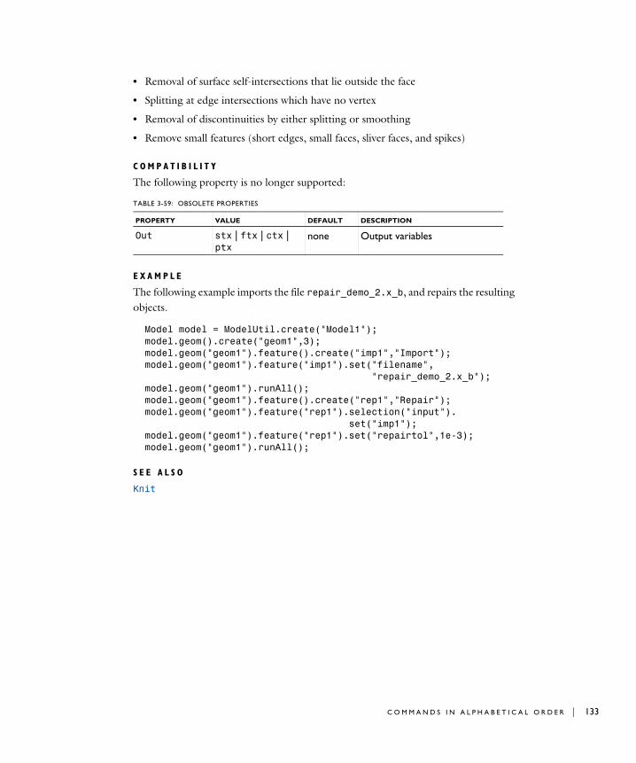
• Removal of surface self-intersections that lie outside the face
• Splitting at edge intersections which have no vertex
• Removal of discontinuities by either splitting or smoothing
• Remove small features (short edges, small faces, sliver faces, and spikes)
C O M P A T I B I L I T Y
The following property is no longer supported:
E X A M P L E
The following example imports the file repair_demo_2.x_b, and repairs the resulting objects.
Model model = ModelUtil.create("Model1");model.geom().create("geom1",3);model.geom("geom1").feature().create("imp1","Import");model.geom("geom1").feature("imp1").set("filename", "repair_demo_2.x_b");model.geom("geom1").runAll();model.geom("geom1").feature().create("rep1","Repair");model.geom("geom1").feature("rep1").selection("input"). set("imp1");model.geom("geom1").feature("rep1").set("repairtol",1e-3);model.geom("geom1").runAll();
S E E A L S O
Knit
TABLE 3-59: OBSOLETE PROPERTIES
PROPERTY VALUE DEFAULT DESCRIPTION
Out stx | ftx | ctx | ptx
none Output variables
C O M M A N D S I N A L P H A B E T I C A L O R D E R | 133

134 | C H A P T E
Rotate
The following additional properties are available with the Design Module.
Scale
The following additional properties are available with the Design Module.
Square
The following additional properties are available with the Design Module.
TABLE 3-60: AVAILABLE PROPERTIES
PROPERTY VALUE DEFAULT DESCRIPTION
rotconstr on | off on Constrain the rotation angle. Constrained properties cannot be modified by constraint and dimension functions.
posconstr String[2] {on, on} Constrain the center of rotation. Constrained properties cannot be modified by constraint and dimension functions.
TABLE 3-61: AVAILABLE PROPERTIES
PROPERTY VALUE DEFAULT DESCRIPTION
posconstr String[2] {on, on} Constrain the center of scaling. Constrained properties cannot be modified by constraint and dimension functions.
TABLE 3-62: AVAILABLE PROPERTIES
PROPERTY VALUE DEFAULT DESCRIPTION
sizeconstr on | off off Constrain the side length. Constrained properties cannot be modified by constraint and dimension functions.
posconstr String[2] {off, off} Constrain the position. Constrained properties cannot be modified by constraint and dimension functions.
rotconstr on | off off Constrain the rotation angle. Constrained properties cannot be modified by constraint and dimension functions.
R 3 : P R O G R A M M I N G A N D C O M M A N D R E F E R E N C E

TangentConstraint
P U R P O S E
Constrain two edges to have a point of tangency. For each edge, you can require that the tangency occurs at an adjacent vertex.
arrowdispl double NaN Displacement of arrow symbol in the normal direction.
labelpos double 0.5 Relative label position along arrow symbol.
arrowint on | off on Internal or external arrow symbol.
TABLE 3-62: AVAILABLE PROPERTIES
PROPERTY VALUE DEFAULT DESCRIPTION
C O M M A N D S I N A L P H A B E T I C A L O R D E R | 135

136 | C H A P T E
D E S C R I P T I O N
S E E A L S O
Angle
Thicken
Generate a solid object by thickening a surface object in 3D.
S Y N T A X
model.geom(<tag>).feature().create(<ftag>,"Thicken");model.geom(<tag>).feature(<ftag>).selection(property);model.geom(<tag>).feature(<ftag>).set(property,<value>);model.geom(<tag>).feature(<ftag>).getType(property);
D E S C R I P T I O N
model.geom(<tag>).feature().create(<ftag>,"Thicken")
TABLE 3-63: AVAILABLE PROPERTIES
PROPERTY VALUE DEFAULT DESCRIPTION
edge1 Selection First edge
point1 vertex | anywhere
anywhere Point of tangency for first edge
vertex1 Selection Vertex for point of tangency (used when point1 is vertex)
edge2 Selection Second edge
point2 vertex | anywhere
anywhere Point of tangency for second edge
vertex2 Selection Vertex for point of tangency (used when point2 is vertex)
helppoint1 double[2] {0, 0} First help point (used when point1 is anywhere)
helppoint2 double[2] {0, 0} Second help point (used when point1 is anywhere)
symbolentity 1 | 2 1 Edge the symbol in the Graphics window is attached to
symboledgpar double 0 Normalized edge parameter for positioning the symbol
symboledgdispl double 20 Symbol displacement in left normal direction from edge (in pixels)
R 3 : P R O G R A M M I N G A N D C O M M A N D R E F E R E N C E

creates a Thicken feature.
Use model.geom(<tag>).feature(<ftag>).selection("input") to select the objects for the thicken operation. The default selection is empty.
For information about the createselection and contributeto properties, search the online help in COMSOL Multiphysics to locate and search all the documentation.
E X A M P L E
Create a cylinder by thickening a disc shaped surface:
Model model = ModelUtil.create("Model1");model.geom().create("geom1", 3);model.geom("geom1").geomRep("cadps");model.geom("geom1").feature().create("wp1", "WorkPlane");model.geom("geom1").feature("wp1").geom().create("c1", "Circle");
TABLE 3-64: AVAILABLE PROPERTIES
PROPERTY VALUE DEFAULT DESCRIPTION
input Selection Input objects
offset symmetric | asymmetric
symmetric Type of offset specification
totalthick double 0 Total thickness (for symmetric offset)
upthick double 0 Upside thickness (for asymmetric offset)
downthick double 0 Downside thickness (for asymmetric offset)
direction normal | vector
normal Offset direction
dirvector double[3] {0,0,1} Offset direction vector
fillet on | off off Fillet offset edges
selresult on | off off Create selections of all resulting objects.
selresultshow all | obj | dom | bnd | edg | pnt | off
dom Show selections of resulting objects in physics, materials, and so on, or in part instances. obj is not available in a component’s geometry. dom, bnd, and edg are not available in all features.
contributeto String none Tag of cumulative selection to contribute to.
C O M M A N D S I N A L P H A B E T I C A L O R D E R | 137

138 | C H A P T E
model.geom("geom1").create("thi1", "Thicken");model.geom("geom1").feature("thi1").selection("input").set(new String[]{"wp1"});model.geom("geom1").feature("thi1").set("totalthick", "0.1");model.geom("geom1").feature("thi1").set("direction", "vector");model.geom("geom1").feature("thi1").set("dirvector", new String[]{"1", "0", "1"});model.geom("geom1").run();
S E E A L S O
Midsurface
TotalEdgeLength
P U R P O S E
Constrain a set of edges to have a given total length. The edges must form a chain and all lie on the same line, circle, or spline.
D E S C R I P T I O N
S E E A L S O
Distance
XDistance
P U R P O S E
Constrain the distance in the x-direction between two geometric entities to a given value.
TABLE 3-65: AVAILABLE PROPERTIES
PROPERTY VALUE DEFAULT DESCRIPTION
edge Selection Edges
length double 0 Total length of edges
labeldispl double NaN Displacement of the label in the Graphics window in left normal direction
labelpos double 0.5 Relative position of the label in the Graphics window along edges
R 3 : P R O G R A M M I N G A N D C O M M A N D R E F E R E N C E

D E S C R I P T I O N
S E E A L S O
YDistance, DirectedDistance, Distance
YDistance
P U R P O S E
Constrain the distance in the y-direction between two geometric entities to a given value.
TABLE 3-66: AVAILABLE PROPERTIES
PROPERTY VALUE DEFAULT DESCRIPTION
entity1 Selection First entity (vertex or curved edge)
entity2 Selection Second entity (vertex or curved edge)
distance double 0 Distance
helppoint1 double[2] {0, 0} First help point
helppoint2 double[2] {0, 0} Second help point
arrowdispl double NaN Displacement of arrow symbol in the Graphics window in the normal direction
labelpos double 0.5 Relative label position along arrow symbol
arrowint on | off on Internal or external arrow symbol
C O M M A N D S I N A L P H A B E T I C A L O R D E R | 139

140 | C H A P T E
D E S C R I P T I O N
S E E A L S O
XDistance, DirectedDistance, Distance
TABLE 3-67: AVAILABLE PROPERTIES
PROPERTY VALUE DEFAULT DESCRIPTION
entity1 Selection First entity (vertex or curved edge)
entity2 Selection Second entity (vertex or curved edge)
distance double 0 Distance
helppoint1 double[2] {0, 0} First help point
helppoint2 double[2] {0, 0} Second help point
arrowdispl double NaN Displacement of arrow symbol in the Graphics window in the normal direction
labelpos double 0.5 Relative label position along arrow symbol
arrowint on | off on Internal or external arrow symbol
R 3 : P R O G R A M M I N G A N D C O M M A N D R E F E R E N C E