The design, construction and performance of the MICE … · 5.3 Optical fibres 31 5.4 Collimators,...
59
Preprint typeset in JINST style - HYPER VERSION MICE-PUB-BEAM-392 IC/HEP/12-07 RAL-P-2012-007 The design, construction and performance of the MICE target C.N. Booth * , P. Hodgson, L. Howlett, R. Nicholson, E. Overton, M. Robinson, P.J. Smith Department of Physics and Astronomy, University of Sheffield, Sheffield S3 7RH, UK [email protected] M. Apollonio a , G. Barber, A. Dobbs, J. Leaver, K.R. Long Department of Physics, Blackett Laboratory, Imperial College London, Exhibition Road, London SW7 2AZ, UK a Now at Diamond Light Source Ltd B. Shepherd STFC Daresbury Laboratory, Daresbury, Cheshire WA4 4AD, UK D. Adams, E. Capocci, E. McCarron, J. Tarrant STFC Rutherford Appleton Laboratory, Chilton, Didcot, Oxfordshire, OX11 0QX, UK ABSTRACT: The pion-production target that serves the MICE Muon Beam consists of a titanium cylinder that is dipped into the halo of the ISIS proton beam. The design and construction of the MICE target system are described along with the quality-assurance procedures, electromagnetic drive and control systems, the readout electronics, and the data-acquisition system. The perfor- mance of the target is presented together with the particle rates delivered to the MICE Muon Beam. Finally, the beam loss in ISIS generated by the operation of the target is evaluated as a function of the particle rate, and the operating parameters of the target are derived. KEYWORDS: Accelerator applications; Targets; Instrumentation for particle accelerators and storage rings; Control and monitor systems online; Overall mechanics designs. * Corresponding author arXiv:1211.6343v5 [physics.ins-det] 6 Mar 2013
Transcript of The design, construction and performance of the MICE … · 5.3 Optical fibres 31 5.4 Collimators,...

Preprint typeset in JINST style - HYPER VERSION MICE-PUB-BEAM-392IC/HEP/12-07
RAL-P-2012-007
The design, construction and performance of theMICE target
C.N. Booth∗, P. Hodgson, L. Howlett, R. Nicholson, E. Overton, M. Robinson,P.J. Smith
Department of Physics and Astronomy, University of Sheffield, Sheffield S3 7RH, [email protected]
M. Apollonioa, G. Barber, A. Dobbs, J. Leaver, K.R. Long
Department of Physics, Blackett Laboratory, Imperial College London, Exhibition Road, LondonSW7 2AZ, UK
aNow at Diamond Light Source Ltd
B. Shepherd
STFC Daresbury Laboratory, Daresbury, Cheshire WA4 4AD, UK
D. Adams, E. Capocci, E. McCarron, J. Tarrant
STFC Rutherford Appleton Laboratory, Chilton, Didcot, Oxfordshire, OX11 0QX, UK
ABSTRACT: The pion-production target that serves the MICE Muon Beam consists of a titaniumcylinder that is dipped into the halo of the ISIS proton beam. The design and construction of theMICE target system are described along with the quality-assurance procedures, electromagneticdrive and control systems, the readout electronics, and the data-acquisition system. The perfor-mance of the target is presented together with the particle rates delivered to the MICE Muon Beam.Finally, the beam loss in ISIS generated by the operation of the target is evaluated as a function ofthe particle rate, and the operating parameters of the target are derived.
KEYWORDS: Accelerator applications; Targets; Instrumentation for particle accelerators andstorage rings; Control and monitor systems online; Overall mechanics designs.
∗Corresponding author
arX
iv:1
211.
6343
v5 [
phys
ics.
ins-
det]
6 M
ar 2
013

Contents
1. Introduction 2
2. Requirements and overview 4
3. Linear motor 63.1 Electromagnetic design 63.2 Stator 7
3.2.1 Coils 73.2.2 Stator Bore 73.2.3 Cooling Jacket 83.2.4 Stator Assembly 10
3.3 Permanent magnets 11
4. Mechanical design and construction 114.1 Target shaft 12
4.1.1 Design 134.1.2 Material 164.1.3 Manufacture 174.1.4 Shaft measurement 18
4.2 Target bearings 204.2.1 Description 204.2.2 Material 204.2.3 Rotational constraint 21
4.3 Stator 234.3.1 Description 23
4.4 Core structure 234.5 Mechanical integration 25
4.5.1 Motorised platform 264.5.2 Bellows and ISIS vessel interface 27
4.6 Magnetic inspection 274.6.1 Stator 284.6.2 Permanent magnets 28
5. Optical position-measurement system 305.1 Optical vane 305.2 Laser source 315.3 Optical fibres 315.4 Collimators, lenses and mechanical mount 315.5 Optical sensors 33
– 1 –
6. Stator operation and power electronics 336.1 Introduction 336.2 Coil current switching sequence 336.3 Magnetic assembly and modelling 356.4 Zero-force points 366.5 Actuation 386.6 Coil switching and current control 406.7 The target power supply 426.8 System placement in ISIS 436.9 Fibre-optic links 44
7. Target control 447.1 Target controller overview 447.2 Control: park, hold and actuate enable modes 457.3 Control: actuation and capture 467.4 The actuate trigger signal 48
8. Performance 488.1 Particle Production and Beam Loss 488.2 Target Lifetime 50
8.2.1 Monitoring 508.2.2 Bearing Performance 518.2.3 Test Programme 53
9. Summary 54
1. Introduction
Muon storage rings have been proposed for use as sources of intense high-energy neutrino beamsin a Neutrino Factory [1] and as the basis for multi-TeV lepton-antilepton colliding-beam facil-ities [2]. To optimise the performance of such facilities requires the phase-space compression(cooling) of the muon beam prior to acceleration and storage. The short muon-lifetime makes itimpossible to employ traditional techniques to cool the beam while maintaining the muon-beamintensity. Ionisation cooling, a process in which the muon beam is passed through a series ofliquid-hydrogen absorbers interspersed with accelerating RF cavities, is the technique proposed tocool the beam. The international Muon Ionisation Cooling Experiment (MICE) will provide anengineering demonstration of the ionisation-cooling technique and will allow the factors affectingthe performance of ionisation-cooling channels to be investigated in detail [3]. Muon beams ofmomenta between 140 MeV/c and 240 MeV/c, with normalised emittances between 2 πmm and10 πmm, will be provided by a purpose-built beam line on the 800 MeV proton synchrotron, ISIS[4], at the Rutherford Appleton Laboratory [5].
– 2 –
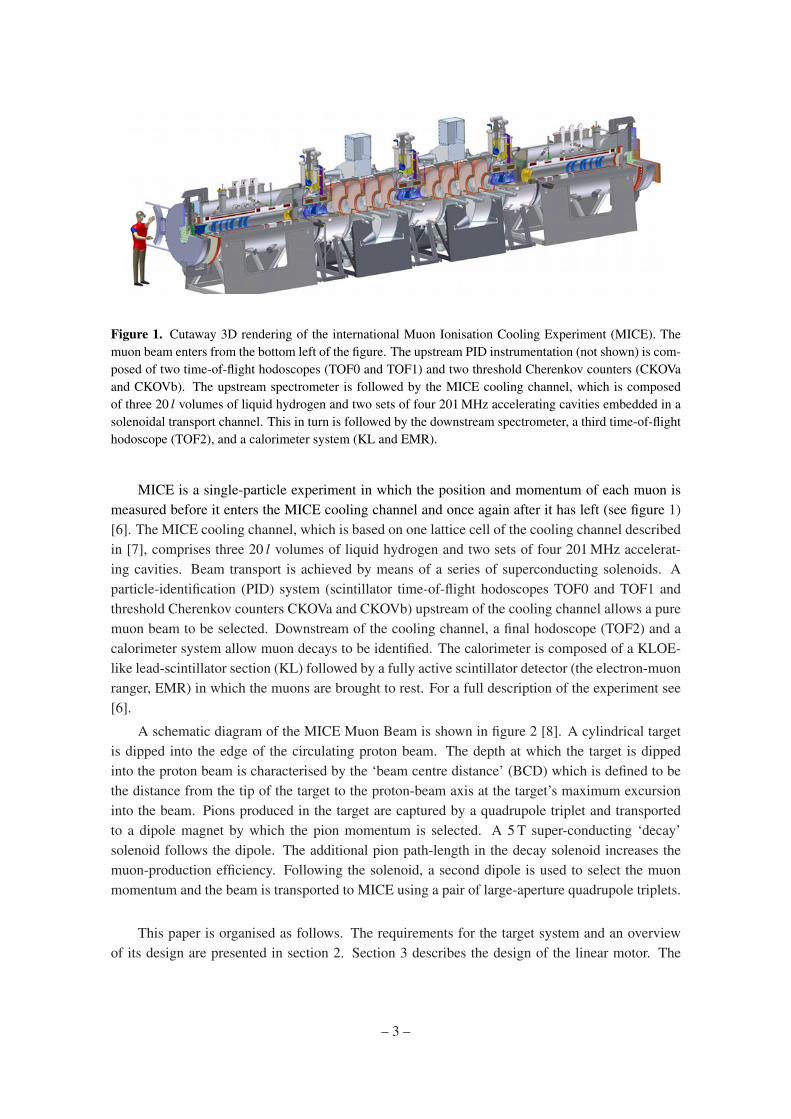
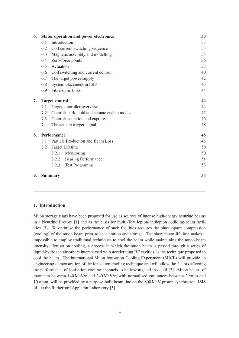
Figure 1. Cutaway 3D rendering of the international Muon Ionisation Cooling Experiment (MICE). Themuon beam enters from the bottom left of the figure. The upstream PID instrumentation (not shown) is com-posed of two time-of-flight hodoscopes (TOF0 and TOF1) and two threshold Cherenkov counters (CKOVaand CKOVb). The upstream spectrometer is followed by the MICE cooling channel, which is composedof three 20 l volumes of liquid hydrogen and two sets of four 201 MHz accelerating cavities embedded in asolenoidal transport channel. This in turn is followed by the downstream spectrometer, a third time-of-flighthodoscope (TOF2), and a calorimeter system (KL and EMR).
MICE is a single-particle experiment in which the position and momentum of each muon ismeasured before it enters the MICE cooling channel and once again after it has left (see figure 1)[6]. The MICE cooling channel, which is based on one lattice cell of the cooling channel describedin [7], comprises three 20 l volumes of liquid hydrogen and two sets of four 201 MHz accelerat-ing cavities. Beam transport is achieved by means of a series of superconducting solenoids. Aparticle-identification (PID) system (scintillator time-of-flight hodoscopes TOF0 and TOF1 andthreshold Cherenkov counters CKOVa and CKOVb) upstream of the cooling channel allows a puremuon beam to be selected. Downstream of the cooling channel, a final hodoscope (TOF2) and acalorimeter system allow muon decays to be identified. The calorimeter is composed of a KLOE-like lead-scintillator section (KL) followed by a fully active scintillator detector (the electron-muonranger, EMR) in which the muons are brought to rest. For a full description of the experiment see[6].
A schematic diagram of the MICE Muon Beam is shown in figure 2 [8]. A cylindrical targetis dipped into the edge of the circulating proton beam. The depth at which the target is dippedinto the proton beam is characterised by the ‘beam centre distance’ (BCD) which is defined to bethe distance from the tip of the target to the proton-beam axis at the target’s maximum excursioninto the beam. Pions produced in the target are captured by a quadrupole triplet and transportedto a dipole magnet by which the pion momentum is selected. A 5 T super-conducting ‘decay’solenoid follows the dipole. The additional pion path-length in the decay solenoid increases themuon-production efficiency. Following the solenoid, a second dipole is used to select the muonmomentum and the beam is transported to MICE using a pair of large-aperture quadrupole triplets.
This paper is organised as follows. The requirements for the target system and an overviewof its design are presented in section 2. Section 3 describes the design of the linear motor. The
– 3 –
Figure 2. The MICE Muon beam-line
mechanical design of the target mechanism and the mechanical interface to the ISIS acceleratoris presented in section 4. Section 5 describes the optical position-measurement system, the powerelectronics used to drive the linear motor is described in section 6 and the control system in section7. The performance of the system, the particle rate delivered for the MICE Muon Beam and thebeam losses induced in ISIS are presented in section 8. Finally, a summary is given in section 9.
2. Requirements and overview
The ISIS synchrotron [4] operates on a basic cycle of 50 Hz. Protons are injected with a kineticenergy of 70 MeV and accelerated to 800 MeV over a period of 10 ms prior to extraction. In thefollowing 10 ms, the currents in the focusing and bending magnets are reduced to their initialvalues, ready for the next pulse of protons to be injected and accelerated.
MICE operation is parasitic to the functioning of ISIS and must cause minimal disruption toits principal function as a spallation neutron source. On selected pulses, the MICE target is causedto dip into the outer low-density halo of the proton beam just before extraction. Pions produced inthe target emerge through a thin window in the ISIS vacuum system in the direction of the MICEmuon beam line. On injection, the proton beam effectively fills the beam pipe. At the locationof the MICE target, the beam has a vertical radius of ∼ 67 mm. During acceleration, the beamshrinks to a radius of about 48 mm. To produce the required muon flux, the target must enter thebeam by at least 5 mm, so a minimum travel of 24 mm is needed. (In practice, the exact position ofthe edge of the beam and the intensity of the halo show long-term variations. The position of thetarget at maximum insertion must therefore be controlled.) The target must be outside the beamenvelope for the first 8 ms of the machine cycle, only entering the beam for the last 1 to 2 ms before
– 4 –

extraction, when the protons are close to their maximum energy. The exact time of insertion mustalso be controllable.
In order to meet the demands described above, a linear electromagnetic drive was implementedto move the target vertically into the beam from above. The technical challenges are considerable.The mechanism must be extremely reliable, to avoid disrupting normal accelerator operation. Itmust provide an acceleration of the order of 780 ms−2 so that the target overtakes the shrinkingbeam envelope and is removed before the next injection. Operation must be precise and repro-ducible, both in position and timing relative to the beam cycle. The mechanism must operatewithin a high radiation environment, and all moving parts must use materials compatible with thestringent constraints of the accelerator’s high-vacuum system. In case of any failure of the targetmechanism, it must be possible to separate it both mechanically and in terms of vacuum from thesynchrotron.
The complete target mechanism, described in detail in this paper, consists of a number ofsub-assemblies.
• The linear electromagnetic drive assembly, which contains:
– The shaft, forming the target at its lower end and carrying a set of fixed permanentmagnets, an optical readout vane at its upper end and a stop to prevent the magnetsfalling from inside the coils in the absence of power;
– A pair of bearings to support, guide and align the shaft;
– The stator, consisting of stationary coils with a water cooling system;
– A central steel tube forming a vacuum barrier between the target shaft and the stationarycoil unit;
– An optical readout enclosure, with sapphire windows.
• The mechanical support assembly, which contains:
– Flanges to provide accurate location of the stator and bearings;
– Conflat seals, to ensure the integrity of the vacuum system.
• The mechanical and vacuum isolation system, to allow the unpowered target to be raisedout of the beam, and the target vacuum to be separated from the accelerator vacuum. Thiscontains:
– A structural frame, carrying the weight of the target assembly;
– A jacking unit and support structure with motorised screw-jack allowing a verticaltravel of approximately 200 mm;
– Centralising units and guide rods that guarantee the target returns to its predefinedposition when lowered into its operating position;
– Edge-welded bellows, to allow relative movement of the components under vacuum;
– A vacuum gate valve to isolate the vacuum systems.
– 5 –
3. Linear motor
A linear actuator was chosen as the most appropriate mechanism to drive the target into the beam.This implementation does not require any moving parts to cross the vacuum chamber walls, andcan be realised without the need for lubricated bearings. For most of the duty cycle, the actuatoris only required to exert a small force on the target, to keep it levitated out of the beam. At theappropriate time, a large accelerating force is required over a short period to accelerate the targetinto and out of the beam and then bring it to rest at its levitated holding position. For this shortperiod, high currents can be employed.
The motor must be of a permanent magnet, brush-less design, as the high acceleration andlarge travel of the motor rule out the placing of coils on the moving parts. The integration ofpermanent magnets into the moving assembly removes the need for electrical contacts between thestator and the moving parts, simplifying the interface between the motor and the ISIS vacuum. Themagnets on the moving components interact with the field produced by a set of stationary coils inthe stator body. These coils are outside the ISIS vacuum, directly wired to the driving electronics.Positioning outside the vacuum also allows the use of a water cooling circuit to remove the energydeposited by Joule heating of the coils.
The initial design of the linear motor was based on studies performed by an electrical engineerspecialising in motor design, and outlined in [9]. The important constraints were to maximise theaccelerating force while minimising the mass of the moving components. The mass of the magneticmaterials thus form a significant fraction of the total mass. Different magnet and coil topologieswere investigated, and the resulting design is documented in the following sections.
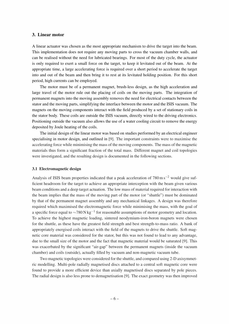
3.1 Electromagnetic design
Analysis of ISIS beam properties indicated that a peak acceleration of 780 m s−2 would give suf-ficient headroom for the target to achieve an appropriate interception with the beam given variousbeam conditions and a deep target actuation. The low mass of material required for interaction withthe beam implies that the mass of the moving part of the motor (or “shuttle”) must be dominatedby that of the permanent magnet assembly and any mechanical linkages. A design was thereforerequired which maximised the electromagnetic force while minimising the mass, with the goal ofa specific force equal to ∼780 N kg−1 for reasonable assumptions of motor geometry and location.To achieve the highest magnetic loading, sintered neodymium-iron-boron magnets were chosenfor the shuttle, as these have the greatest field strength and best strength-to-mass ratio. A bank ofappropriately energised coils interact with the field of the magnets to drive the shuttle. Soft mag-netic core material was considered for the stator, but this was not found to lead to any advantage,due to the small size of the motor and the fact that magnetic material would be saturated [9]. Thiswas exacerbated by the significant “air-gap” between the permanent magnets (inside the vacuumchamber) and coils (outside), actually filled by vacuum and non-magnetic vacuum tube.
Two magnetic topologies were considered for the shuttle, and compared using 2-D axisymmet-ric modelling. Multi-pole radially magnetised discs attached to a central soft magnetic core werefound to provide a more efficient device than axially magnetised discs separated by pole pieces.The radial design is also less prone to demagnetisation [9]. The exact geometry was then improved
– 6 –
by iterative finite element studies. Test results from a prototype motor were used to validate thedesign.
3.2 Stator
The stator, which is cylindrical in shape, contains a set of flat coils mounted around a thin-walledsteel tube. After winding, each coil is impregnated with insulating varnish to form a stable compactunit. During assembly six 25 µm copper shims are sandwiched between each pair of coils tofacilitate heat conduction out of the coil stack. The addition of the copper shims gives a coil pitchof 3 mm. Connecting leads from the coils are led radially outwards. Three thermocouples areinserted between three pairs of coils to enable the temperature of the coil stack to be monitored. Acoiled copper tube soldered onto a solid copper jacket is placed around the coils and is in contactwith the copper shims. This carries the cooling water, the temperature of which is monitored ateither end with two more thermocouples. The entire assembly is inserted into an aluminium outercylinder, the stator body, with the insulated copper wires and the cooling pipes emerging througha slit in the side. The individual coils are wired up at terminal blocks placed external to the statorbody.
3.2.1 Coils
The stator contains twenty-four identical coils that are stacked vertically and numbered one totwenty four starting from the top of the stator. The stator coils are responsible for interacting withthe permanent magnets on the shaft both to levitate the target shaft when the target is being heldout of the ISIS beam and to produce the accelerating force when the target needs to be inserted intothe beam. (A motorised jacking platform is used to raise the target from the beam when not in use,as described in section 4.5.)
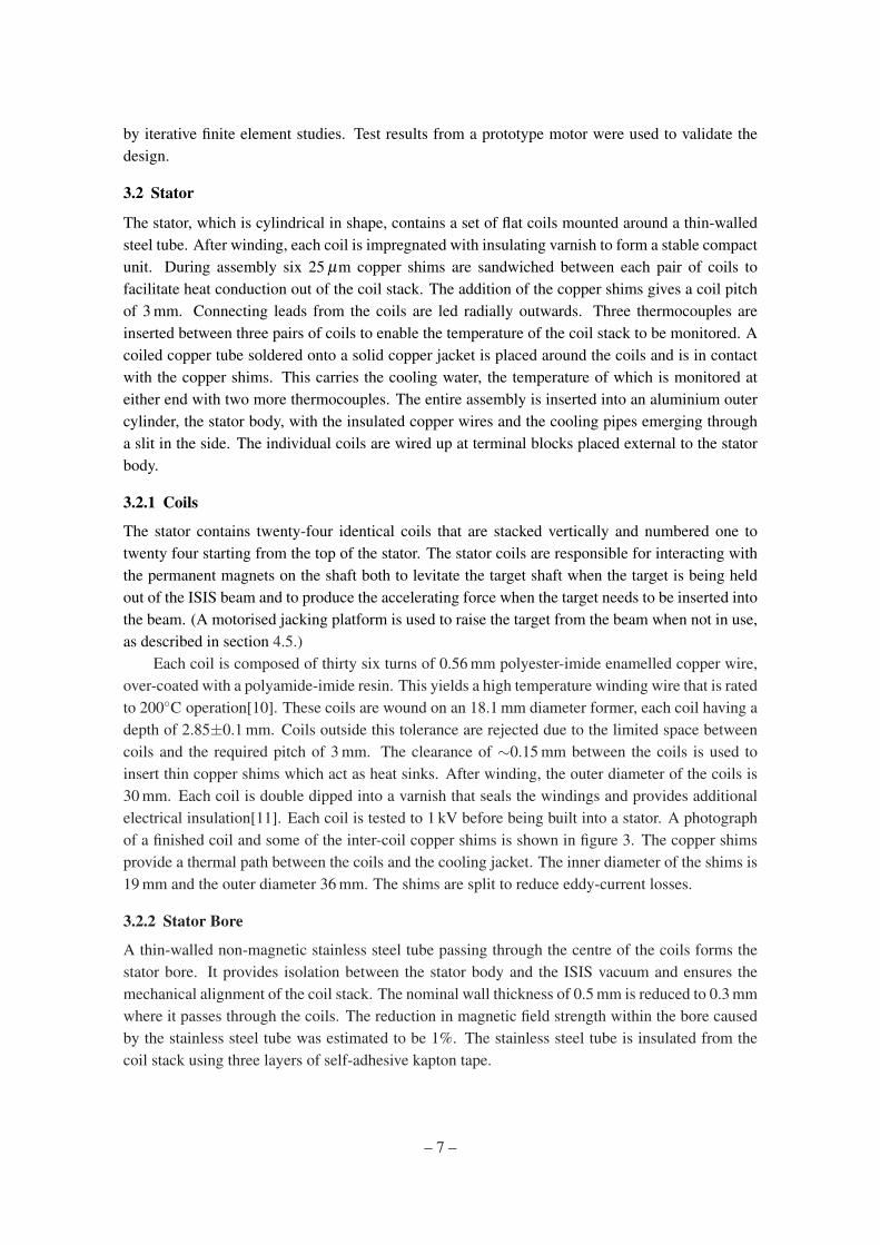
Each coil is composed of thirty six turns of 0.56 mm polyester-imide enamelled copper wire,over-coated with a polyamide-imide resin. This yields a high temperature winding wire that is ratedto 200C operation[10]. These coils are wound on an 18.1 mm diameter former, each coil having adepth of 2.85±0.1 mm. Coils outside this tolerance are rejected due to the limited space betweencoils and the required pitch of 3 mm. The clearance of ∼0.15 mm between the coils is used toinsert thin copper shims which act as heat sinks. After winding, the outer diameter of the coils is30 mm. Each coil is double dipped into a varnish that seals the windings and provides additionalelectrical insulation[11]. Each coil is tested to 1 kV before being built into a stator. A photographof a finished coil and some of the inter-coil copper shims is shown in figure 3. The copper shimsprovide a thermal path between the coils and the cooling jacket. The inner diameter of the shims is19 mm and the outer diameter 36 mm. The shims are split to reduce eddy-current losses.
3.2.2 Stator Bore
A thin-walled non-magnetic stainless steel tube passing through the centre of the coils forms thestator bore. It provides isolation between the stator body and the ISIS vacuum and ensures themechanical alignment of the coil stack. The nominal wall thickness of 0.5 mm is reduced to 0.3 mmwhere it passes through the coils. The reduction in magnetic field strength within the bore causedby the stainless steel tube was estimated to be 1%. The stainless steel tube is insulated from thecoil stack using three layers of self-adhesive kapton tape.
– 7 –
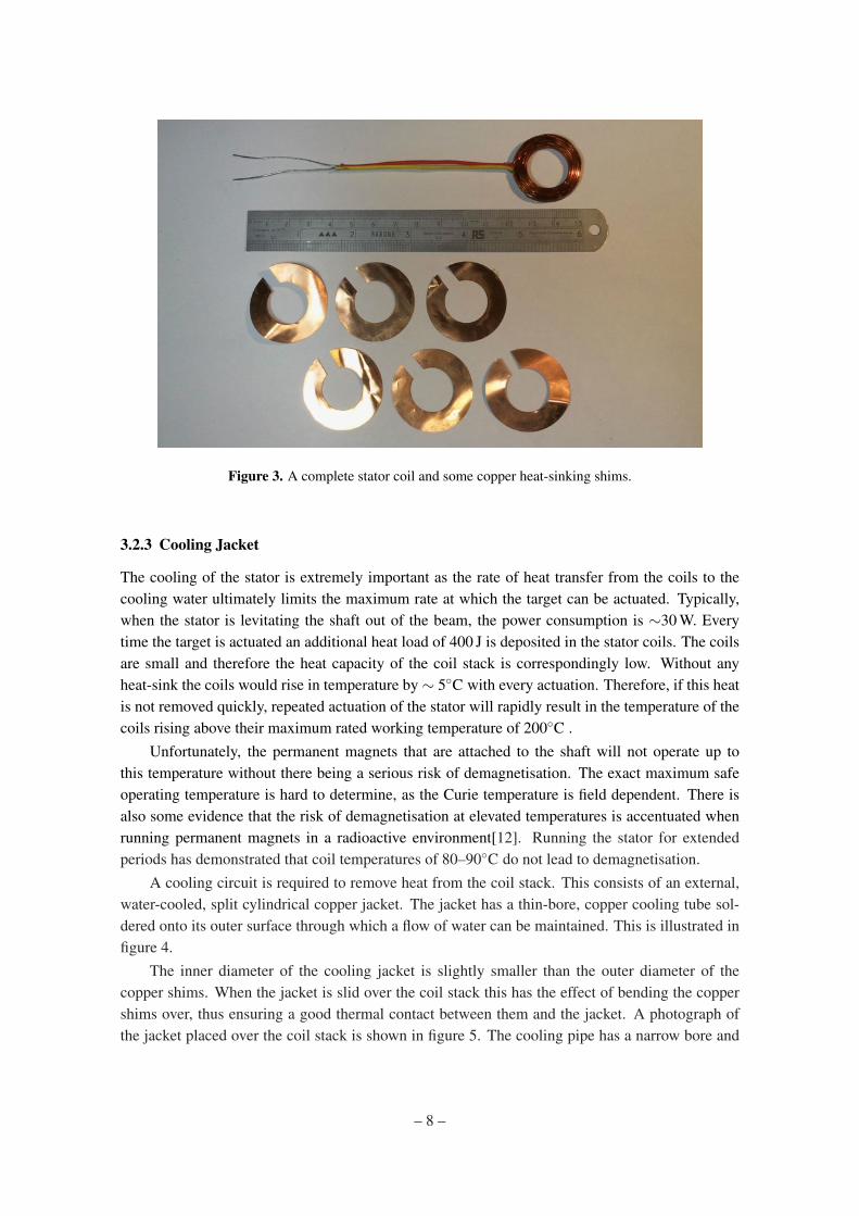
Figure 3. A complete stator coil and some copper heat-sinking shims.
3.2.3 Cooling Jacket
The cooling of the stator is extremely important as the rate of heat transfer from the coils to thecooling water ultimately limits the maximum rate at which the target can be actuated. Typically,when the stator is levitating the shaft out of the beam, the power consumption is ∼30 W. Everytime the target is actuated an additional heat load of 400 J is deposited in the stator coils. The coilsare small and therefore the heat capacity of the coil stack is correspondingly low. Without anyheat-sink the coils would rise in temperature by ∼ 5C with every actuation. Therefore, if this heatis not removed quickly, repeated actuation of the stator will rapidly result in the temperature of thecoils rising above their maximum rated working temperature of 200C .
Unfortunately, the permanent magnets that are attached to the shaft will not operate up tothis temperature without there being a serious risk of demagnetisation. The exact maximum safeoperating temperature is hard to determine, as the Curie temperature is field dependent. There isalso some evidence that the risk of demagnetisation at elevated temperatures is accentuated whenrunning permanent magnets in a radioactive environment[12]. Running the stator for extendedperiods has demonstrated that coil temperatures of 80–90C do not lead to demagnetisation.
A cooling circuit is required to remove heat from the coil stack. This consists of an external,water-cooled, split cylindrical copper jacket. The jacket has a thin-bore, copper cooling tube sol-dered onto its outer surface through which a flow of water can be maintained. This is illustrated infigure 4.
The inner diameter of the cooling jacket is slightly smaller than the outer diameter of thecopper shims. When the jacket is slid over the coil stack this has the effect of bending the coppershims over, thus ensuring a good thermal contact between them and the jacket. A photograph ofthe jacket placed over the coil stack is shown in figure 5. The cooling pipe has a narrow bore and
– 8 –
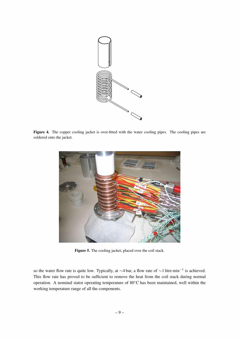
Figure 4. The copper cooling jacket is over-fitted with the water cooling pipes. The cooling pipes aresoldered onto the jacket.
Figure 5. The cooling jacket, placed over the coil stack.
so the water flow rate is quite low. Typically, at ∼4 bar, a flow rate of ∼1 litre min−1 is achieved.This flow rate has proved to be sufficient to remove the heat from the coil stack during normaloperation. A nominal stator operating temperature of 80C has been maintained, well within theworking temperature range of all the components.
– 9 –
3.2.4 Stator Assembly
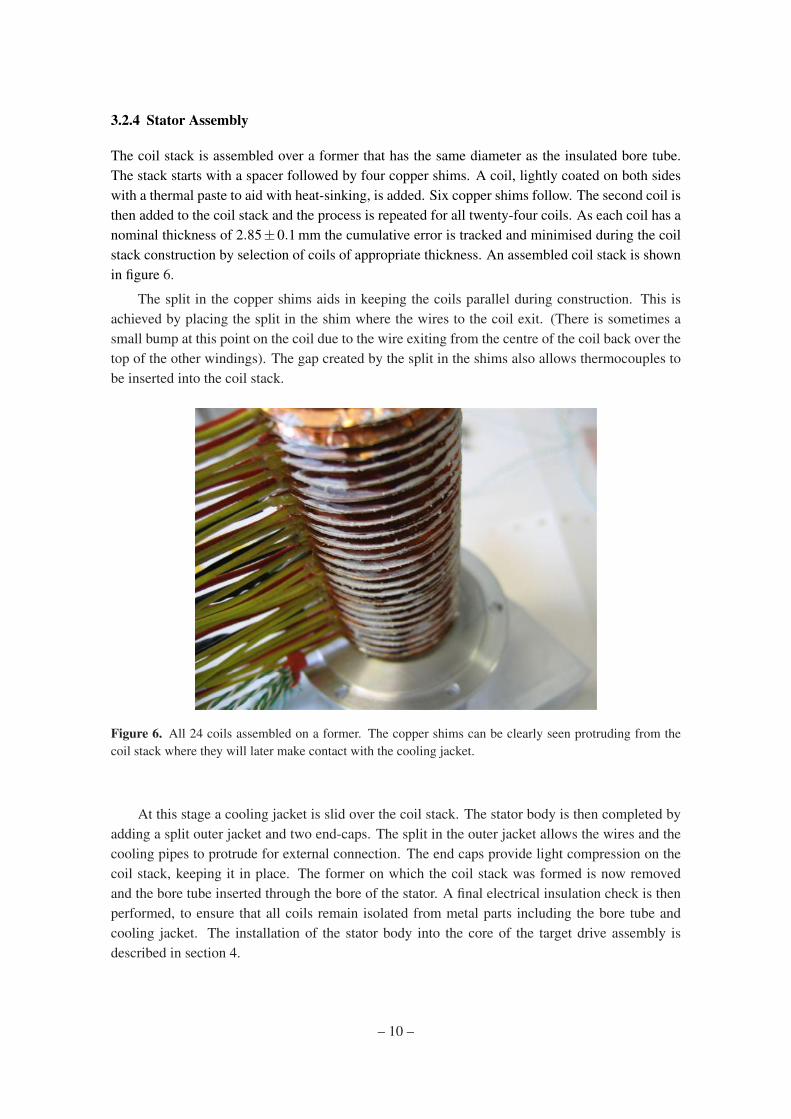
The coil stack is assembled over a former that has the same diameter as the insulated bore tube.The stack starts with a spacer followed by four copper shims. A coil, lightly coated on both sideswith a thermal paste to aid with heat-sinking, is added. Six copper shims follow. The second coil isthen added to the coil stack and the process is repeated for all twenty-four coils. As each coil has anominal thickness of 2.85±0.1 mm the cumulative error is tracked and minimised during the coilstack construction by selection of coils of appropriate thickness. An assembled coil stack is shownin figure 6.
The split in the copper shims aids in keeping the coils parallel during construction. This isachieved by placing the split in the shim where the wires to the coil exit. (There is sometimes asmall bump at this point on the coil due to the wire exiting from the centre of the coil back over thetop of the other windings). The gap created by the split in the shims also allows thermocouples tobe inserted into the coil stack.
Figure 6. All 24 coils assembled on a former. The copper shims can be clearly seen protruding from thecoil stack where they will later make contact with the cooling jacket.
At this stage a cooling jacket is slid over the coil stack. The stator body is then completed byadding a split outer jacket and two end-caps. The split in the outer jacket allows the wires and thecooling pipes to protrude for external connection. The end caps provide light compression on thecoil stack, keeping it in place. The former on which the coil stack was formed is now removedand the bore tube inserted through the bore of the stator. A final electrical insulation check is thenperformed, to ensure that all coils remain isolated from metal parts including the bore tube andcooling jacket. The installation of the stator body into the core of the target drive assembly isdescribed in section 4.
– 10 –
3.3 Permanent magnets
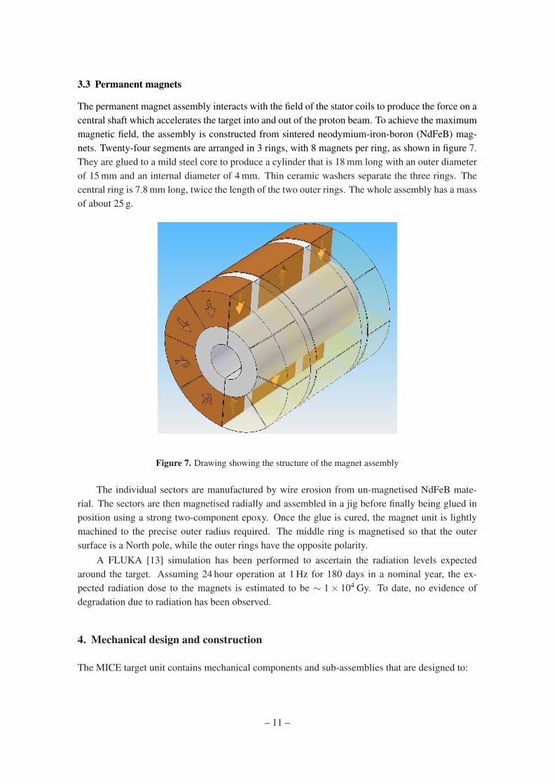
The permanent magnet assembly interacts with the field of the stator coils to produce the force on acentral shaft which accelerates the target into and out of the proton beam. To achieve the maximummagnetic field, the assembly is constructed from sintered neodymium-iron-boron (NdFeB) mag-nets. Twenty-four segments are arranged in 3 rings, with 8 magnets per ring, as shown in figure 7.They are glued to a mild steel core to produce a cylinder that is 18 mm long with an outer diameterof 15 mm and an internal diameter of 4 mm. Thin ceramic washers separate the three rings. Thecentral ring is 7.8 mm long, twice the length of the two outer rings. The whole assembly has a massof about 25 g.
Figure 7. Drawing showing the structure of the magnet assembly
The individual sectors are manufactured by wire erosion from un-magnetised NdFeB mate-rial. The sectors are then magnetised radially and assembled in a jig before finally being glued inposition using a strong two-component epoxy. Once the glue is cured, the magnet unit is lightlymachined to the precise outer radius required. The middle ring is magnetised so that the outersurface is a North pole, while the outer rings have the opposite polarity.
A FLUKA [13] simulation has been performed to ascertain the radiation levels expectedaround the target. Assuming 24 hour operation at 1 Hz for 180 days in a nominal year, the ex-pected radiation dose to the magnets is estimated to be ∼ 1× 10⁴ Gy. To date, no evidence ofdegradation due to radiation has been observed.
4. Mechanical design and construction
The MICE target unit contains mechanical components and sub-assemblies that are designed to:
– 11 –
• Combine accurately all mechanical, electronic, electrical-power and optical-readout func-tions into a single unit;
• Provide a vacuum tight volume connected hermetically to the ISIS beam-line;
• Enable target operation by:
– Providing controlled drive of the target’s shaft into and out of the beam;
– Enabling the velocity and location of the shaft to be determined;
– Constraining the shaft along its path of travel thus preventing significant off-axis move-ment;
– Providing stiffness in the shaft that resists significant deformation and vibration duringoperation.
• Eliminate the possibility of a failure that prevents continued operation of ISIS beam, includ-ing:
– Breaking of the shaft such that part falls into the circulating beam;
– Failure of welds or seals causing a leak into the ISIS vacuum chamber; and
– Contamination of the ISIS vacuum chamber, particularly with metallic or other dustthat could contaminate the RF cavities.
• Deliver an operational lifetime that is sufficient to allow a rolling programme of maintenanceat appropriately infrequent intervals.
4.1 Target shaft
The shaft comprises of two sections of titanium (Ti) alloy grade 5 (6% Al, 4% V). The sectionsare a solid upper section and a lower tubular section with various functional features on each. Thetwo halves are joined with a shrink-fitted plug-and-socket arrangement then electron-beam weldedtogether. The shaft is coated with a hard diamond-like carbon (DLC) coating that acts as a bearingsurface. The shaft is finally fitted with a permanent magnet, a slotted graticule for position read-outand the associated fixings and fasteners.
The shaft is 528 mm long and, when fully assembled with the magnet, slotted graticule andfixings, has a weight of ∼ 51 g. A radially segmented, permanent-magnet assembly is bonded tothe shaft and held with a mechanical clamp of minimal mass (1.5 g). The stator accelerates andthen decelerates the shaft in both the down-stroke and the up-stroke with a maximum travel in eachdirection of around 48 mm. The shaft achieves this 96 mm of reciprocating movement in about30 ms before dwelling and then dipping again; with the dwell the shaft dips at a frequency of justunder 1 Hz. The tip of the shaft has a cylindrical cross section of ∼11.5 mm2 (5.95 mm outsidediameter and 4.55 mm inside diameter); as it is an integral part of the tubular lower shaft it is grade5 titanium alloy. It is the tip of the hollow cylinder that momentarily grazes the halo of the ISISbeam to produce pions.
The production quality of the target shaft is the most critical aspect of all the manufacturingprocess. The shaft is manufactured within very tight dimensional and geometric form tolerances.
– 12 –
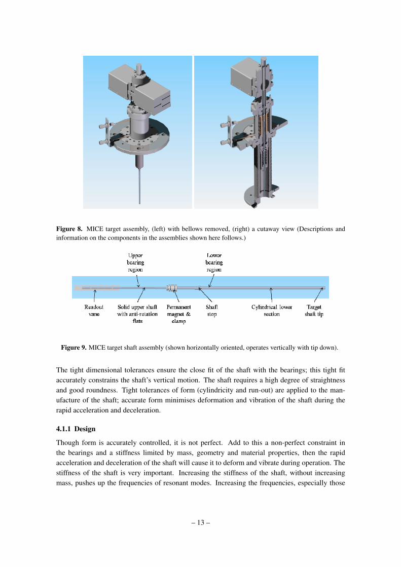
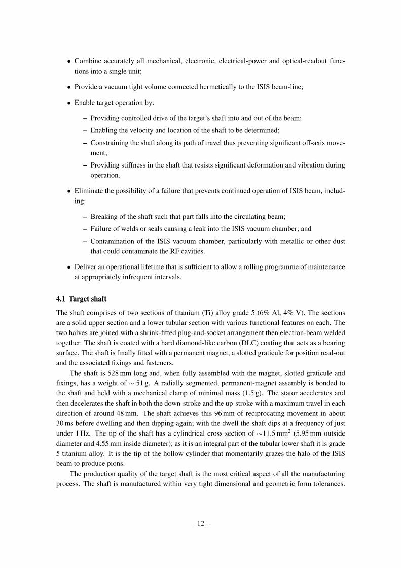
Figure 8. MICE target assembly, (left) with bellows removed, (right) a cutaway view (Descriptions andinformation on the components in the assemblies shown here follows.)
Figure 9. MICE target shaft assembly (shown horizontally oriented, operates vertically with tip down).
The tight dimensional tolerances ensure the close fit of the shaft with the bearings; this tight fitaccurately constrains the shaft’s vertical motion. The shaft requires a high degree of straightnessand good roundness. Tight tolerances of form (cylindricity and run-out) are applied to the man-ufacture of the shaft; accurate form minimises deformation and vibration of the shaft during therapid acceleration and deceleration.
4.1.1 Design
Though form is accurately controlled, it is not perfect. Add to this a non-perfect constraint inthe bearings and a stiffness limited by mass, geometry and material properties, then the rapidacceleration and deceleration of the shaft will cause it to deform and vibrate during operation. Thestiffness of the shaft is very important. Increasing the stiffness of the shaft, without increasingmass, pushes up the frequencies of resonant modes. Increasing the frequencies, especially those
– 13 –

Figure 10. Output plot of FE modal analysis of shortened shaft with ‘O’ shaped lower section.
of the first few resonant modes, reduces the number of resonant modes the shaft passes through asit is accelerated and decelerated. Excitation of vibrations in the shaft may arise from a number ofsources, including:
• Large changes in velocity take place at ∼ 15 ms intervals, i.e. twice over the 30 ms cycle. Ifthe natural frequency of the shaft is close to 33 Hz or 67 Hz some distortion will be induced.
• The switching of power from one set of coils to the next may introduce an excitation force.The longitudinal driving force (up to 50 N) may be accompanied by off-axis torque or lateralforces as the sequential coil-switching takes place during dipping. The frequency and sever-ity of the excitation would be directly linked to the timing and magnitude of these forces.The timing of the switching is variable as the shaft is accelerated and decelerated in bothdirections, so the frequency of excitation is variable too. This may cause the shaft to passthrough several excitation frequencies that correspond to the shaft’s resonant frequencies.The magnitude of the excitation depends on the force seen by the shaft when switching be-tween coils; this is related to the quality of the coils and their axial location relative to thepermanent magnet. With a 0.5 mm offset in coaxiality between the permanent magnet andthe coil’s magnetic centre the lateral forces have been calculated to be up to 2.5 N and thetorque up to 32.5 mN m.
• The unit or surrounding support frames may be excited by the dipping shaft. There is poten-tial for this vibration to transfer back from the support frame to the shaft through the statorand the bearings. There is significant vibration felt on the test frame after each dip.
A tubular, ‘O’ section shaft was shown to have sufficient stiffness. A finite-element (FE) modalanalysis showed the 1st and 2nd resonant modes at 50 Hz, but the 3rd and 4th at 68 Hz.
The tubular lower section is created by rough-machining a bar to leave a slightly oversizedexternal profile, including an integrated mechanical end-stop. This is then heat-treated to removeresidual stresses. The bore is then wire eroded to 4.55 mm ID over the length of the lower shaft(about 320 mm); if internal stresses were present the shaft might deform along its length as thismaterial is removed. After wire erosion the external profile, including the stop, is finished to final
– 14 –
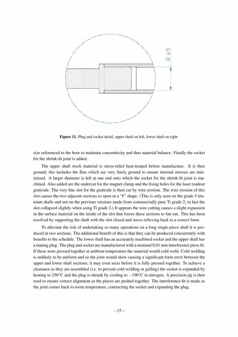
Figure 11. Plug and socket detail, upper shaft on left, lower shaft on right
size referenced to the bore to maintain concentricity and thus material balance. Finally the socketfor the shrink-fit joint is added.
The upper shaft stock material is stress-relief heat-treated before manufacture. It is thenground; this includes the flats which are very finely ground to ensure internal stresses are min-imised. A larger diameter is left at one end onto which the socket for the shrink-fit joint is ma-chined. Also added are the undercut for the magnet clamp and the fixing holes for the laser readoutgraticule. The very fine slot for the graticule is then cut by wire erosion. The wire erosion of thisslot causes the two adjacent sections to open in a ‘Y’ shape. (This is only seen on the grade 5 tita-nium shafts and not on the previous versions made from commercially pure Ti grade 2; in fact theslot collapsed slightly when using Ti grade 2.) It appears the wire cutting causes a slight expansionin the surface material on the inside of the slot that forces these sections to fan out. This has beenresolved by supporting the shaft with the slot closed and stress-relieving back to a correct form.
To alleviate the risk of undertaking so many operations on a long single-piece shaft it is pro-duced in two sections. The additional benefit of this is that they can be produced concurrently withbenefits to the schedule. The lower shaft has an accurately machined socket and the upper shaft hasa mating plug. The plug and socket are manufactured with a nominal 0.01 mm interference press fit.If these were pressed together at ambient temperature the material would cold-weld. Cold-weldingis unlikely to be uniform and so the joint would skew causing a significant form error between theupper and lower shaft sections; it may even seize before it is fully pressed together. To achieve aclearance as they are assembled (i.e. to prevent cold welding or galling) the socket is expanded byheating to 250C and the plug is shrunk by cooling to −190C in nitrogen. A precision jig is thenused to ensure correct alignment as the pieces are pushed together. The interference-fit is made asthe joint comes back to room temperature, contracting the socket and expanding the plug.
– 15 –
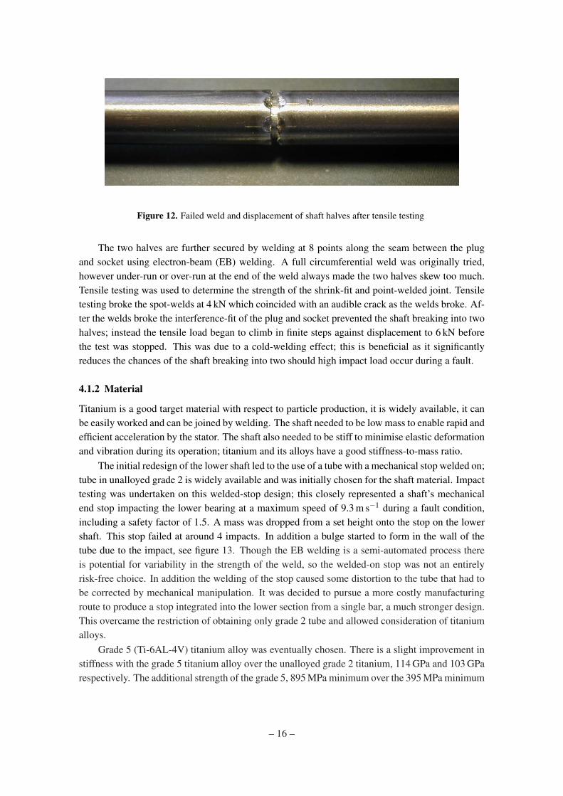
Figure 12. Failed weld and displacement of shaft halves after tensile testing
The two halves are further secured by welding at 8 points along the seam between the plugand socket using electron-beam (EB) welding. A full circumferential weld was originally tried,however under-run or over-run at the end of the weld always made the two halves skew too much.Tensile testing was used to determine the strength of the shrink-fit and point-welded joint. Tensiletesting broke the spot-welds at 4 kN which coincided with an audible crack as the welds broke. Af-ter the welds broke the interference-fit of the plug and socket prevented the shaft breaking into twohalves; instead the tensile load began to climb in finite steps against displacement to 6 kN beforethe test was stopped. This was due to a cold-welding effect; this is beneficial as it significantlyreduces the chances of the shaft breaking into two should high impact load occur during a fault.
4.1.2 Material
Titanium is a good target material with respect to particle production, it is widely available, it canbe easily worked and can be joined by welding. The shaft needed to be low mass to enable rapid andefficient acceleration by the stator. The shaft also needed to be stiff to minimise elastic deformationand vibration during its operation; titanium and its alloys have a good stiffness-to-mass ratio.
The initial redesign of the lower shaft led to the use of a tube with a mechanical stop welded on;tube in unalloyed grade 2 is widely available and was initially chosen for the shaft material. Impacttesting was undertaken on this welded-stop design; this closely represented a shaft’s mechanicalend stop impacting the lower bearing at a maximum speed of 9.3 m s−1 during a fault condition,including a safety factor of 1.5. A mass was dropped from a set height onto the stop on the lowershaft. This stop failed at around 4 impacts. In addition a bulge started to form in the wall of thetube due to the impact, see figure 13. Though the EB welding is a semi-automated process thereis potential for variability in the strength of the weld, so the welded-on stop was not an entirelyrisk-free choice. In addition the welding of the stop caused some distortion to the tube that had tobe corrected by mechanical manipulation. It was decided to pursue a more costly manufacturingroute to produce a stop integrated into the lower section from a single bar, a much stronger design.This overcame the restriction of obtaining only grade 2 tube and allowed consideration of titaniumalloys.
Grade 5 (Ti-6AL-4V) titanium alloy was eventually chosen. There is a slight improvement instiffness with the grade 5 titanium alloy over the unalloyed grade 2 titanium, 114 GPa and 103 GParespectively. The additional strength of the grade 5, 895 MPa minimum over the 395 MPa minimum
– 16 –
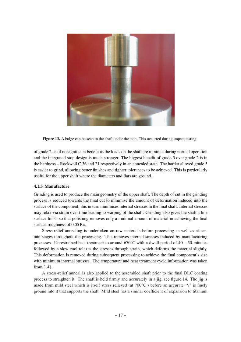
Figure 13. A bulge can be seen in the shaft under the stop. This occurred during impact testing.
of grade 2, is of no significant benefit as the loads on the shaft are minimal during normal operationand the integrated-stop design is much stronger. The biggest benefit of grade 5 over grade 2 is inthe hardness – Rockwell C 36 and 21 respectively in an annealed state. The harder alloyed grade 5is easier to grind, allowing better finishes and tighter tolerances to be achieved. This is particularlyuseful for the upper shaft where the diameters and flats are ground.
4.1.3 Manufacture
Grinding is used to produce the main geometry of the upper shaft. The depth of cut in the grindingprocess is reduced towards the final cut to minimise the amount of deformation induced into thesurface of the component; this in turn minimises internal stresses in the final shaft. Internal stressesmay relax via strain over time leading to warping of the shaft. Grinding also gives the shaft a finesurface finish so that polishing removes only a minimal amount of material in achieving the finalsurface roughness of 0.05 Ra.
Stress-relief annealing is undertaken on raw materials before processing as well as at cer-tain stages throughout the processing. This removes internal stresses induced by manufacturingprocesses. Unrestrained heat treatment to around 670C with a dwell period of 40− 50 minutesfollowed by a slow cool relaxes the stresses through strain, which deforms the material slightly.This deformation is removed during subsequent processing to achieve the final component’s sizewith minimum internal stresses. The temperature and heat treatment cycle information was takenfrom [14].
A stress-relief anneal is also applied to the assembled shaft prior to the final DLC coatingprocess to straighten it. The shaft is held firmly and accurately in a jig, see figure 14. The jig ismade from mild steel which is itself stress relieved (at 700C ) before an accurate ‘V’ is finelyground into it that supports the shaft. Mild steel has a similar coefficient of expansion to titanium
– 17 –
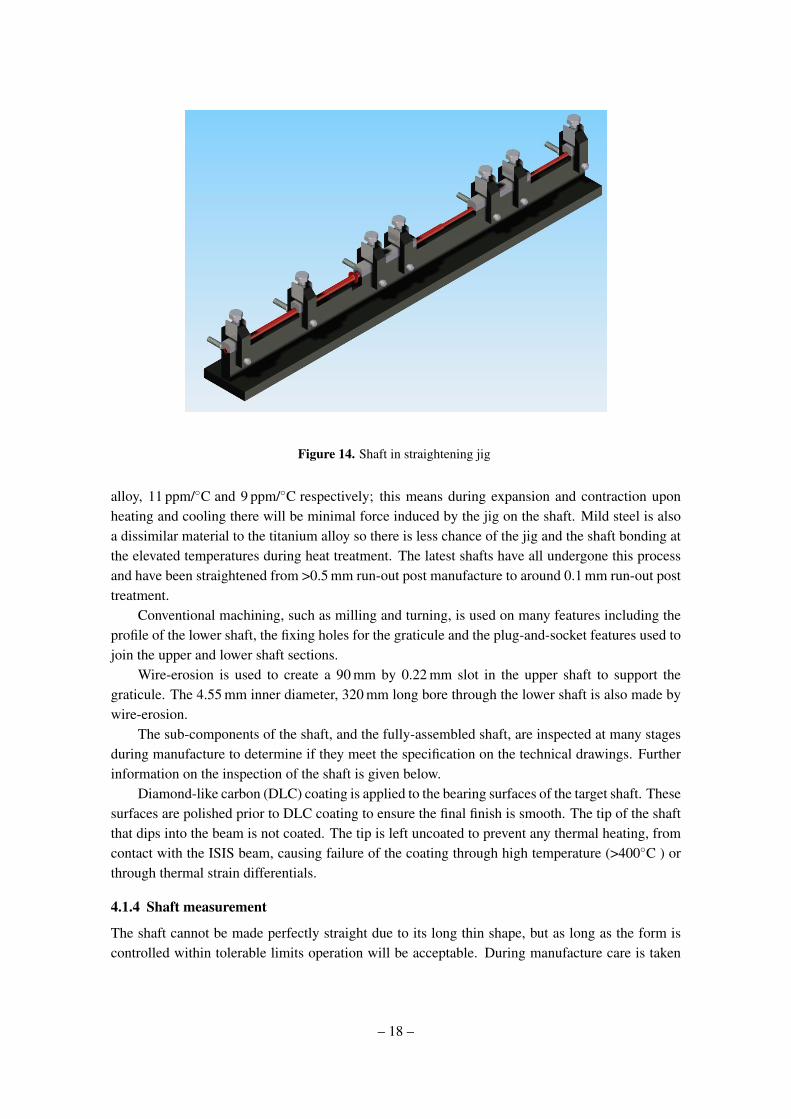
Figure 14. Shaft in straightening jig
alloy, 11 ppm/C and 9 ppm/C respectively; this means during expansion and contraction uponheating and cooling there will be minimal force induced by the jig on the shaft. Mild steel is alsoa dissimilar material to the titanium alloy so there is less chance of the jig and the shaft bonding atthe elevated temperatures during heat treatment. The latest shafts have all undergone this processand have been straightened from >0.5 mm run-out post manufacture to around 0.1 mm run-out posttreatment.
Conventional machining, such as milling and turning, is used on many features including theprofile of the lower shaft, the fixing holes for the graticule and the plug-and-socket features used tojoin the upper and lower shaft sections.
Wire-erosion is used to create a 90 mm by 0.22 mm slot in the upper shaft to support thegraticule. The 4.55 mm inner diameter, 320 mm long bore through the lower shaft is also made bywire-erosion.
The sub-components of the shaft, and the fully-assembled shaft, are inspected at many stagesduring manufacture to determine if they meet the specification on the technical drawings. Furtherinformation on the inspection of the shaft is given below.
Diamond-like carbon (DLC) coating is applied to the bearing surfaces of the target shaft. Thesesurfaces are polished prior to DLC coating to ensure the final finish is smooth. The tip of the shaftthat dips into the beam is not coated. The tip is left uncoated to prevent any thermal heating, fromcontact with the ISIS beam, causing failure of the coating through high temperature (>400C ) orthrough thermal strain differentials.
4.1.4 Shaft measurement
The shaft cannot be made perfectly straight due to its long thin shape, but as long as the form iscontrolled within tolerable limits operation will be acceptable. During manufacture care is taken
– 18 –
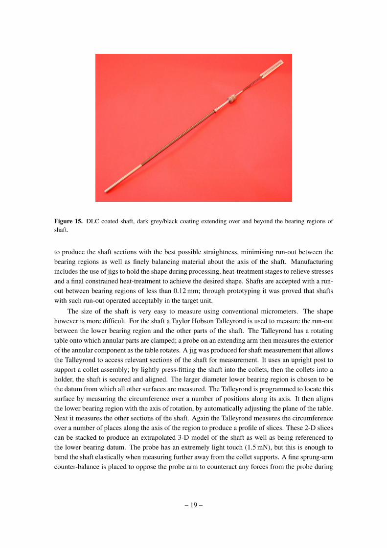
Figure 15. DLC coated shaft, dark grey/black coating extending over and beyond the bearing regions ofshaft.
to produce the shaft sections with the best possible straightness, minimising run-out between thebearing regions as well as finely balancing material about the axis of the shaft. Manufacturingincludes the use of jigs to hold the shape during processing, heat-treatment stages to relieve stressesand a final constrained heat-treatment to achieve the desired shape. Shafts are accepted with a run-out between bearing regions of less than 0.12 mm; through prototyping it was proved that shaftswith such run-out operated acceptably in the target unit.
The size of the shaft is very easy to measure using conventional micrometers. The shapehowever is more difficult. For the shaft a Taylor Hobson Talleyrond is used to measure the run-outbetween the lower bearing region and the other parts of the shaft. The Talleyrond has a rotatingtable onto which annular parts are clamped; a probe on an extending arm then measures the exteriorof the annular component as the table rotates. A jig was produced for shaft measurement that allowsthe Talleyrond to access relevant sections of the shaft for measurement. It uses an upright post tosupport a collet assembly; by lightly press-fitting the shaft into the collets, then the collets into aholder, the shaft is secured and aligned. The larger diameter lower bearing region is chosen to bethe datum from which all other surfaces are measured. The Talleyrond is programmed to locate thissurface by measuring the circumference over a number of positions along its axis. It then alignsthe lower bearing region with the axis of rotation, by automatically adjusting the plane of the table.Next it measures the other sections of the shaft. Again the Talleyrond measures the circumferenceover a number of places along the axis of the region to produce a profile of slices. These 2-D slicescan be stacked to produce an extrapolated 3-D model of the shaft as well as being referenced tothe lower bearing datum. The probe has an extremely light touch (1.5 mN), but this is enough tobend the shaft elastically when measuring further away from the collet supports. A fine sprung-armcounter-balance is placed to oppose the probe arm to counteract any forces from the probe during
– 19 –
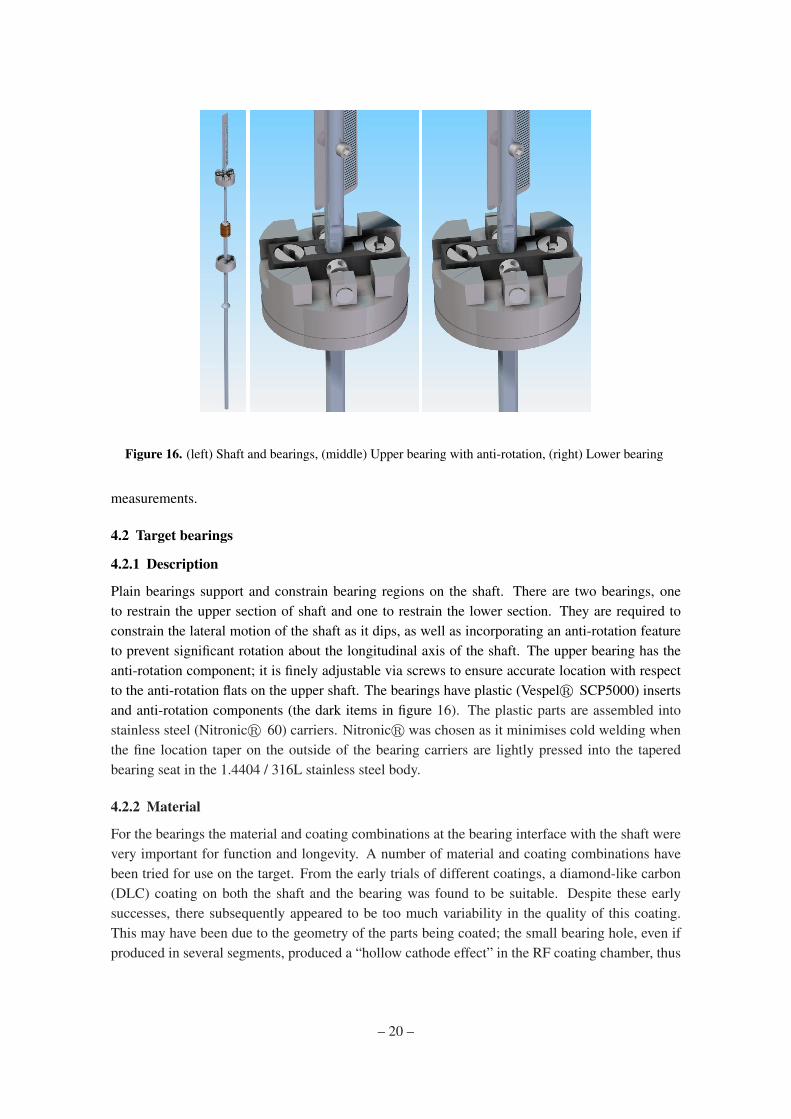
Figure 16. (left) Shaft and bearings, (middle) Upper bearing with anti-rotation, (right) Lower bearing
measurements.
4.2 Target bearings
4.2.1 Description
Plain bearings support and constrain bearing regions on the shaft. There are two bearings, oneto restrain the upper section of shaft and one to restrain the lower section. They are required toconstrain the lateral motion of the shaft as it dips, as well as incorporating an anti-rotation featureto prevent significant rotation about the longitudinal axis of the shaft. The upper bearing has theanti-rotation component; it is finely adjustable via screws to ensure accurate location with respectto the anti-rotation flats on the upper shaft. The bearings have plastic (Vespelr SCP5000) insertsand anti-rotation components (the dark items in figure 16). The plastic parts are assembled intostainless steel (Nitronicr 60) carriers. Nitronicr was chosen as it minimises cold welding whenthe fine location taper on the outside of the bearing carriers are lightly pressed into the taperedbearing seat in the 1.4404 / 316L stainless steel body.
4.2.2 Material
For the bearings the material and coating combinations at the bearing interface with the shaft werevery important for function and longevity. A number of material and coating combinations havebeen tried for use on the target. From the early trials of different coatings, a diamond-like carbon(DLC) coating on both the shaft and the bearing was found to be suitable. Despite these earlysuccesses, there subsequently appeared to be too much variability in the quality of this coating.This may have been due to the geometry of the parts being coated; the small bearing hole, even ifproduced in several segments, produced a “hollow cathode effect” in the RF coating chamber, thus
– 20 –

variability in the thickness and adhesion of the DLC coating. This variability led to coatings onsome shafts and bearings wearing away rapidly in later trials.
The alternative to DLC came from cryocooler technology as designed and built by STFC’sCryogenics and Magnetics Group. The cryocoolers have demonstrated in excess of 1010 cyclesin a dry helium atmosphere. The material combination used in these cryocoolers is titanium (bothcommercially pure and 6% Al, 4% V) against Vespelr SP-3 grade. The SP-3 grade of Vespelr is apolyimide that contains molybdenum-disulphide (MoS2). MoS2 is a dry lubricant which lowers thecoefficient of friction. However MoS2 was rejected on the grounds that long-lived isotopes mightbe produced in the high radiation environment. DuPontTM Technical were contacted to determineif an unfilled alternative may be suitable. From the following requirements it was determined thatVespelr SCP5000 would meet the needs of the target when operating on the ISIS beam-line.
Bearing surfaces have a higher coefficient of friction in the ISIS vacuum of 10−7 mbar [15],i.e. without the presence of moisture or lubricating films. A high coefficient of friction betweenbearing surfaces will increase the power required to drive the shaft, it will cause accelerated wearof the bearing surfaces and it will raise the temperature at the bearing interface through frictionalheating. SCP-5000 was recommended for use as it has a relatively low coefficient of friction, evenin a vacuum environment, of 0.26 or better [16].
Bearing materials are required to be tolerant to the effects of the nuclear radiation generatedin ISIS, i.e. their mechanical properties must not change significantly during the operational lifeof the unit. Vespelr is a polyimide which will tolerate a significant total accumulated ionisingradiation dose before a loss in mechanical properties.
Particles created during wear should be kept to a minimum. If they are created they must bemanaged and contained within the unit. This is particularly important for particles that have becomeactivated, for health and safety reasons. In addition particles should not be released from the unit asthey may damage the RF cavities adjacent to the MICE target in ISIS. Dust is produced when usingthe Vespelr bearings, however with a finely polished shaft this has been minimised. The targetunit has been fitted with an extended housing with dust-traps to prevent the dust produced fromthe Vespelr escaping outside of the unit, see figure 17. The bearing surfaces need to withstanda significant operational life and be able to be manufactured with fine surface finishes and tighttolerances to minimise the rate of wear; Vespelr is a relatively hard plastic so suits this.
The material must not significantly out-gas in the ISIS vacuum. Out-gassing tests were under-taken on vacuum-baked samples of Vespelr SCP5000 (80C for 72 hours) which were shown tobe acceptable for use on the ISIS beam-line provided the total volume was kept below 3 cm3.
4.2.3 Rotational constraint
The position of the shaft is determined using an optical vane (section 5.1) which must be heldroughly perpendicular to laser beams. The orientation of the shaft must thus be restricted to arange of about ±10. The range is limited to less than ±3 by providing the upper section of theshaft with a pair of finely-polished parallel flats that run against a flat-faced Vespelr anti-rotationcomponent on the bearing, see figure 18. The flat faces of the anti-rotation component are finelyadjusted so that the flats on the upper shaft only contact them if the shaft rotates. In trials using ananti-rotation component with two completely flat faces, it was found that after running for some
– 21 –
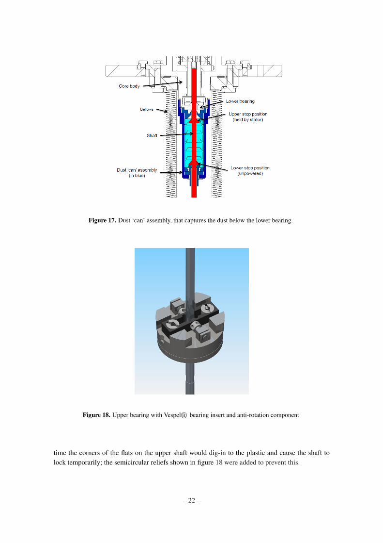
Figure 17. Dust ‘can’ assembly, that captures the dust below the lower bearing.
Figure 18. Upper bearing with Vespelr bearing insert and anti-rotation component
time the corners of the flats on the upper shaft would dig-in to the plastic and cause the shaft tolock temporarily; the semicircular reliefs shown in figure 18 were added to prevent this.
– 22 –
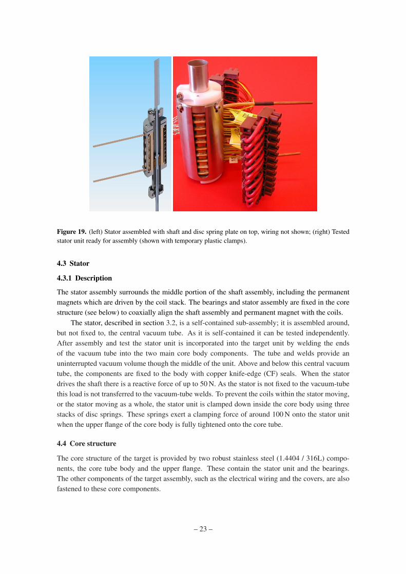
Figure 19. (left) Stator assembled with shaft and disc spring plate on top, wiring not shown; (right) Testedstator unit ready for assembly (shown with temporary plastic clamps).
4.3 Stator
4.3.1 Description
The stator assembly surrounds the middle portion of the shaft assembly, including the permanentmagnets which are driven by the coil stack. The bearings and stator assembly are fixed in the corestructure (see below) to coaxially align the shaft assembly and permanent magnet with the coils.
The stator, described in section 3.2, is a self-contained sub-assembly; it is assembled around,but not fixed to, the central vacuum tube. As it is self-contained it can be tested independently.After assembly and test the stator unit is incorporated into the target unit by welding the endsof the vacuum tube into the two main core body components. The tube and welds provide anuninterrupted vacuum volume though the middle of the unit. Above and below this central vacuumtube, the components are fixed to the body with copper knife-edge (CF) seals. When the statordrives the shaft there is a reactive force of up to 50 N. As the stator is not fixed to the vacuum-tubethis load is not transferred to the vacuum-tube welds. To prevent the coils within the stator moving,or the stator moving as a whole, the stator unit is clamped down inside the core body using threestacks of disc springs. These springs exert a clamping force of around 100 N onto the stator unitwhen the upper flange of the core body is fully tightened onto the core tube.
4.4 Core structure
The core structure of the target is provided by two robust stainless steel (1.4404 / 316L) compo-nents, the core tube body and the upper flange. These contain the stator unit and the bearings.The other components of the target assembly, such as the electrical wiring and the covers, are alsofastened to these core components.
– 23 –
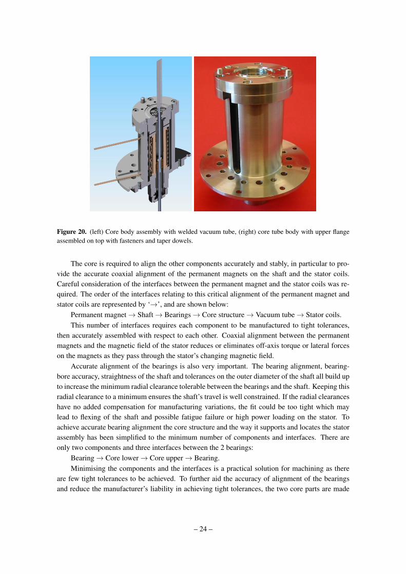
Figure 20. (left) Core body assembly with welded vacuum tube, (right) core tube body with upper flangeassembled on top with fasteners and taper dowels.
The core is required to align the other components accurately and stably, in particular to pro-vide the accurate coaxial alignment of the permanent magnets on the shaft and the stator coils.Careful consideration of the interfaces between the permanent magnet and the stator coils was re-quired. The order of the interfaces relating to this critical alignment of the permanent magnet andstator coils are represented by ‘→’, and are shown below:
Permanent magnet→ Shaft→ Bearings→ Core structure→ Vacuum tube→ Stator coils.This number of interfaces requires each component to be manufactured to tight tolerances,
then accurately assembled with respect to each other. Coaxial alignment between the permanentmagnets and the magnetic field of the stator reduces or eliminates off-axis torque or lateral forceson the magnets as they pass through the stator’s changing magnetic field.
Accurate alignment of the bearings is also very important. The bearing alignment, bearing-bore accuracy, straightness of the shaft and tolerances on the outer diameter of the shaft all build upto increase the minimum radial clearance tolerable between the bearings and the shaft. Keeping thisradial clearance to a minimum ensures the shaft’s travel is well constrained. If the radial clearanceshave no added compensation for manufacturing variations, the fit could be too tight which maylead to flexing of the shaft and possible fatigue failure or high power loading on the stator. Toachieve accurate bearing alignment the core structure and the way it supports and locates the statorassembly has been simplified to the minimum number of components and interfaces. There areonly two components and three interfaces between the 2 bearings:
Bearing→ Core lower→ Core upper→ Bearing.Minimising the components and the interfaces is a practical solution for machining as there
are few tight tolerances to be achieved. To further aid the accuracy of alignment of the bearingsand reduce the manufacturer’s liability in achieving tight tolerances, the two core parts are made
– 24 –
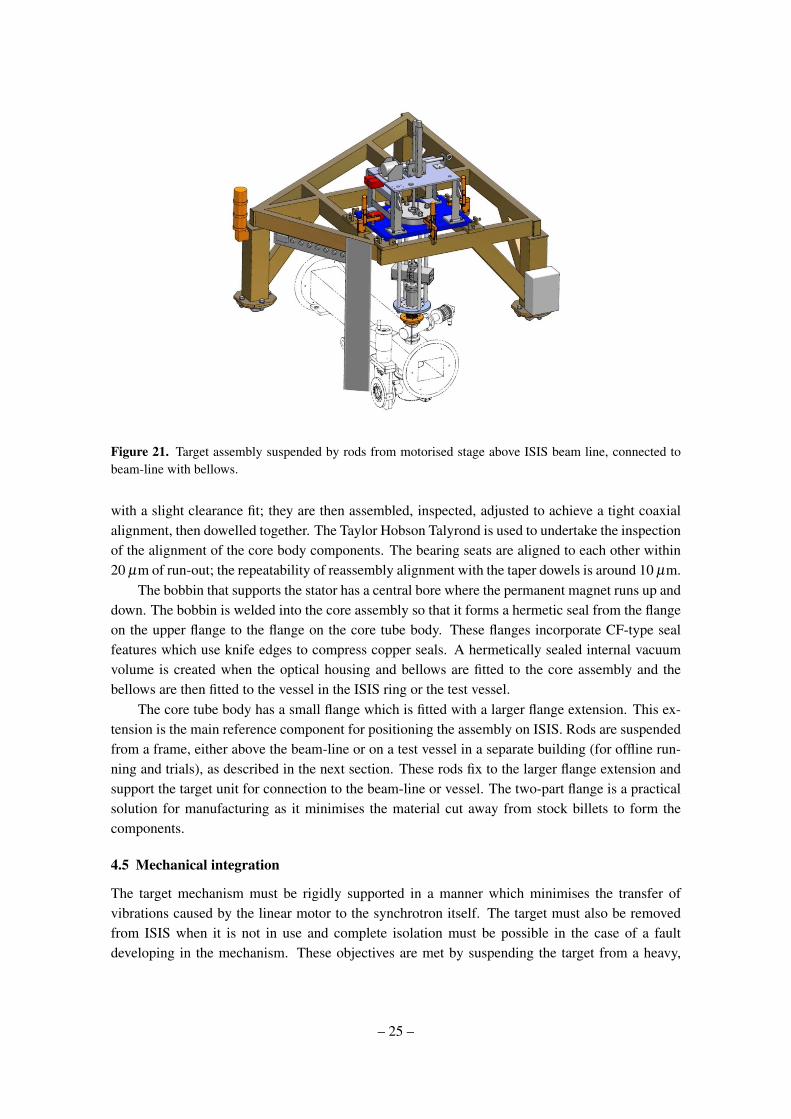
Figure 21. Target assembly suspended by rods from motorised stage above ISIS beam line, connected tobeam-line with bellows.
with a slight clearance fit; they are then assembled, inspected, adjusted to achieve a tight coaxialalignment, then dowelled together. The Taylor Hobson Talyrond is used to undertake the inspectionof the alignment of the core body components. The bearing seats are aligned to each other within20 µm of run-out; the repeatability of reassembly alignment with the taper dowels is around 10 µm.
The bobbin that supports the stator has a central bore where the permanent magnet runs up anddown. The bobbin is welded into the core assembly so that it forms a hermetic seal from the flangeon the upper flange to the flange on the core tube body. These flanges incorporate CF-type sealfeatures which use knife edges to compress copper seals. A hermetically sealed internal vacuumvolume is created when the optical housing and bellows are fitted to the core assembly and thebellows are then fitted to the vessel in the ISIS ring or the test vessel.
The core tube body has a small flange which is fitted with a larger flange extension. This ex-tension is the main reference component for positioning the assembly on ISIS. Rods are suspendedfrom a frame, either above the beam-line or on a test vessel in a separate building (for offline run-ning and trials), as described in the next section. These rods fix to the larger flange extension andsupport the target unit for connection to the beam-line or vessel. The two-part flange is a practicalsolution for manufacturing as it minimises the material cut away from stock billets to form thecomponents.
4.5 Mechanical integration
The target mechanism must be rigidly supported in a manner which minimises the transfer ofvibrations caused by the linear motor to the synchrotron itself. The target must also be removedfrom ISIS when it is not in use and complete isolation must be possible in the case of a faultdeveloping in the mechanism. These objectives are met by suspending the target from a heavy,
– 25 –
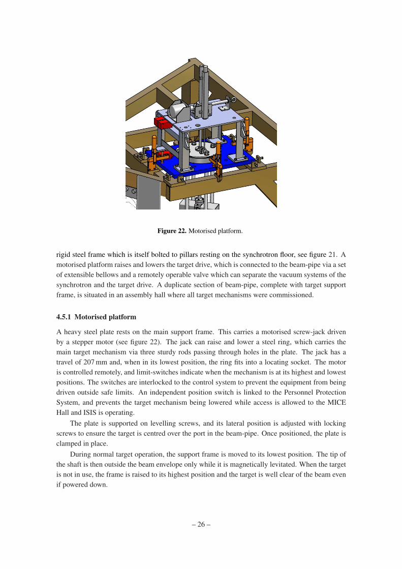
Figure 22. Motorised platform.
rigid steel frame which is itself bolted to pillars resting on the synchrotron floor, see figure 21. Amotorised platform raises and lowers the target drive, which is connected to the beam-pipe via a setof extensible bellows and a remotely operable valve which can separate the vacuum systems of thesynchrotron and the target drive. A duplicate section of beam-pipe, complete with target supportframe, is situated in an assembly hall where all target mechanisms were commissioned.
4.5.1 Motorised platform
A heavy steel plate rests on the main support frame. This carries a motorised screw-jack drivenby a stepper motor (see figure 22). The jack can raise and lower a steel ring, which carries themain target mechanism via three sturdy rods passing through holes in the plate. The jack has atravel of 207 mm and, when in its lowest position, the ring fits into a locating socket. The motoris controlled remotely, and limit-switches indicate when the mechanism is at its highest and lowestpositions. The switches are interlocked to the control system to prevent the equipment from beingdriven outside safe limits. An independent position switch is linked to the Personnel ProtectionSystem, and prevents the target mechanism being lowered while access is allowed to the MICEHall and ISIS is operating.
The plate is supported on levelling screws, and its lateral position is adjusted with lockingscrews to ensure the target is centred over the port in the beam-pipe. Once positioned, the plate isclamped in place.
During normal target operation, the support frame is moved to its lowest position. The tip ofthe shaft is then outside the beam envelope only while it is magnetically levitated. When the targetis not in use, the frame is raised to its highest position and the target is well clear of the beam evenif powered down.
– 26 –
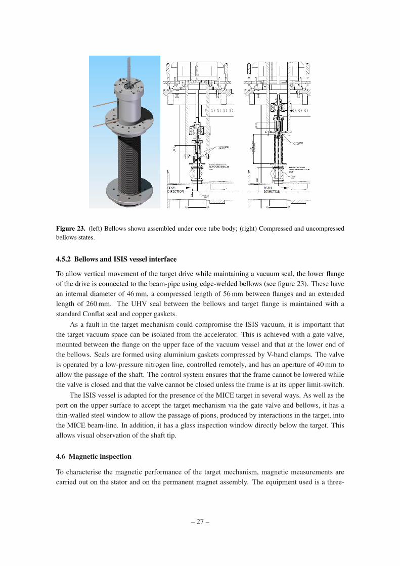
Figure 23. (left) Bellows shown assembled under core tube body; (right) Compressed and uncompressedbellows states.
4.5.2 Bellows and ISIS vessel interface
To allow vertical movement of the target drive while maintaining a vacuum seal, the lower flangeof the drive is connected to the beam-pipe using edge-welded bellows (see figure 23). These havean internal diameter of 46 mm, a compressed length of 56 mm between flanges and an extendedlength of 260 mm. The UHV seal between the bellows and target flange is maintained with astandard Conflat seal and copper gaskets.
As a fault in the target mechanism could compromise the ISIS vacuum, it is important thatthe target vacuum space can be isolated from the accelerator. This is achieved with a gate valve,mounted between the flange on the upper face of the vacuum vessel and that at the lower end ofthe bellows. Seals are formed using aluminium gaskets compressed by V-band clamps. The valveis operated by a low-pressure nitrogen line, controlled remotely, and has an aperture of 40 mm toallow the passage of the shaft. The control system ensures that the frame cannot be lowered whilethe valve is closed and that the valve cannot be closed unless the frame is at its upper limit-switch.
The ISIS vessel is adapted for the presence of the MICE target in several ways. As well as theport on the upper surface to accept the target mechanism via the gate valve and bellows, it has athin-walled steel window to allow the passage of pions, produced by interactions in the target, intothe MICE beam-line. In addition, it has a glass inspection window directly below the target. Thisallows visual observation of the shaft tip.
4.6 Magnetic inspection
To characterise the magnetic performance of the target mechanism, magnetic measurements arecarried out on the stator and on the permanent magnet assembly. The equipment used is a three-
– 27 –
axis Hall probe mounted on the end of a travelling arm. The position of the probe can be set to aresolution of 1 µm in three axes.
4.6.1 Stator
For the stator, measurements are required to define the position of the magnetic centre of the coilsrelative to the mechanical centre. If the coils are offset, the small radial field they generate mayhave the effect of moving the shaft laterally as it passes through the stator. Accurate alignment ofthe magnetic centre is therefore important to minimise wear on the bearings during operation.
The coils are powered using a constant current of 7 A; this is lower than the peak currentwhen the shaft is dipped into the beam due to heating concerns – a constant current of 60 A wouldoverheat the coils. The current of 7 A heats the stator to around 50C when water cooling is used.
The stator is set up and aligned to the measurement bench. A cross-hair on the end of the Hallprobe is viewed through a telescope as the probe is moved up and down the bench; this allows thetelescope axis to be set parallel to the bench axis. Cylindrical inserts with a precisely machinedcentral hole are placed in either end of the stator bore in turn, to allow the stator axis to be alignedparallel to the bench axis. The estimated accuracy of this procedure is around 100 µm at each end,which gives an overall alignment accuracy of 0.8 mrad over the 180 mm length of the stator.
An initial scan of the stator along the longitudinal (z) axis shows a series of peaks correspond-ing to the individual coils. To find the centre of each coil, a two-dimensional scan at each peakposition is carried out (Figure 24). The magnetic centre is the point at which the longitudinal fieldis a minimum. The longitudinal field is fitted to the function:
Bz = ax2 +bx+ cy2 +dy+ exy+ f
The centre point can then be found from the fit to the data, using the formulae:
x0 =2bc−de4ac− e2 ; y0 =
be−2ade2−4ac
4.6.2 Permanent magnets
For the permanent magnets, measurements are carried out to determine azimuthal variability of theradial field (i.e. Br vs θ ). Due to variations in the PM blocks, there is a certain amount of variationin the peak (and trough) values of the radial field. An assembly with smaller differences betweenthe peaks would be preferable, as it may reduce lateral movement and vibration of the target shaftduring operation.
The PM assembly is attached to a rotational stage in order to map the radial field as a functionof angle and longitudinal position. In this case, the Hall probe is attached to a spring-loaded headto keep it the same distance from the PMs (about 1 mm) as the assembly is rotated. This was foundto be necessary since the PM assembly was not parallel to the Hall probe axis. The effect is small– a few tens of microns as the PM assembly is rotated – but enough to give a significant differencein the measured field, as the field drops off rapidly with radius. Figure 25 shows a plot of the radialfield versus angle.
– 28 –
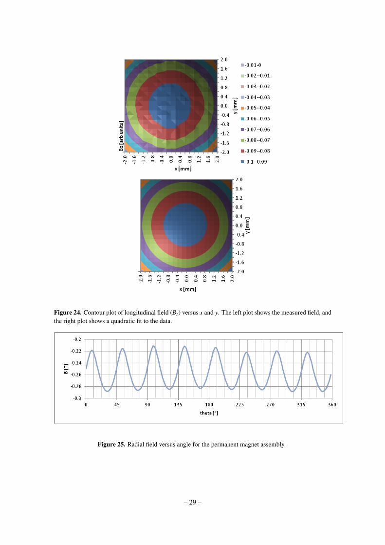
Figure 24. Contour plot of longitudinal field (Bz) versus x and y. The left plot shows the measured field, andthe right plot shows a quadratic fit to the data.
Figure 25. Radial field versus angle for the permanent magnet assembly.
– 29 –
5. Optical position-measurement system
In order to switch the current through the coil stack at the correct time to drive the shaft, it isnecessary to sense the position of the shaft while it is moving. To avoid disrupting the motion ofthe low-mass shaft by mechanical contact, and to remove the necessity for electrical feed-throughstraversing the vacuum wall, an optical method is adopted. Furthermore, since active electricalcomponents would not survive in the high radiation environment near the target, optical fibres areused to convey the signals, with all sensitive electronics being placed outside the accelerator vault(in the experiment control room some 100 metres away).
A graticule, or vane, attached to the shaft and interrupting a light beam will generate a seriesof pulses, which could be used to determine the speed but not the direction of movement of theshaft. If it is arranged such that two beams are interrupted by the vane, with the pulse trains being90 out of phase, then both speed and direction can be determined. (This is known as a quadraturesystem.) With a third beam producing a pulse at only one well-defined point, a zero of position canbe defined. In this way, by counting pulses away from the zero, an absolute position measurementcan be made.
In addition to providing feedback to the controller, position measurement allows the trajectoryof the target to be monitored and recorded by the data acquisition system. This enables the long-term monitoring of the stability of the mechanism and the diagnosis of fault conditions.
5.1 Optical vane
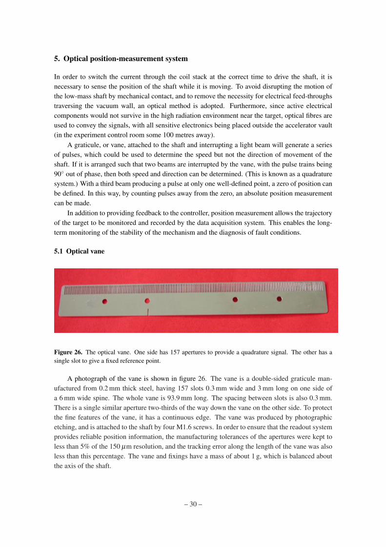
Figure 26. The optical vane. One side has 157 apertures to provide a quadrature signal. The other has asingle slot to give a fixed reference point.
A photograph of the vane is shown in figure 26. The vane is a double-sided graticule man-ufactured from 0.2 mm thick steel, having 157 slots 0.3 mm wide and 3 mm long on one side ofa 6 mm wide spine. The whole vane is 93.9 mm long. The spacing between slots is also 0.3 mm.There is a single similar aperture two-thirds of the way down the vane on the other side. To protectthe fine features of the vane, it has a continuous edge. The vane was produced by photographicetching, and is attached to the shaft by four M1.6 screws. In order to ensure that the readout systemprovides reliable position information, the manufacturing tolerances of the apertures were kept toless than 5% of the 150 µm resolution, and the tracking error along the length of the vane was alsoless than this percentage. The vane and fixings have a mass of about 1 g, which is balanced aboutthe axis of the shaft.
– 30 –

5.2 Laser source
Three fibre-coupled solid-state lasers provide the light beams which intercept the vane. Commer-cial red (635 nm) lasers, with a variable 0 to 2.5 mW output power are used. Visible light hasadvantages both for alignment and safety. The milli-Watt power level is required due to significantlosses in the optical system owing to the number of optical interfaces. Maximising the light onthe optical sensors (Section 5.5) increases the signal to noise ratio and simplifies the design of theelectronic amplifiers.
In practice, the lasers are not operated at maximum power, but at about 1 mW. This leavessufficient overhead (both in light source and amplification gain) to adjust for any degradation in theoptical fibres, e.g. increased attenuation as a result of radiation damage.
5.3 Optical fibres
Two types of optical fibre are used. On the transmitting side, single mode fibres are required toachieve the necessary small spot size at the focal point and hence at the plane of the vane. On thereceiving side, 200 µm multimode fibres are used.
The single mode fibres used are SM600 with FC-to-FC connectors [17]. These fibres have acore of pure silica, which is a radiation-hard material and so ideal for the operating environmentof the target. If single-mode fibres were used on the receiving side, the collimators would haveto be aligned to an extremely high precision and it would be hard to achieve an adequate lighttransmission. Multimode fibres have a higher acceptance, so make the alignment less critical. Thefibres used are BFH37/200 purchased from Thorlabs, with SMA to SMA connectors [18].
5.4 Collimators, lenses and mechanical mount
Collimators and lenses are used to focus the light from the fibres to a spot in the plane of theoptical vane (where it needs to be significantly smaller than the pitch of the vane) and to receivethe transmitted light coupling it into the return fibre. The collimator is a commercial unit whichproduces parallel light from the diverging beam emitted by the fibre. Collimators with a focallength of 15.3 mm are used, as the longer focal length minimises the final spot size. The focusinglens, with focal length 45 mm, is attached to the front of the collimators by inserting it into a holderwhich is screwed onto the front of the collimator as shown in figure 27. On the transmitting side,aspheric double achromatic lenses are used to obtain the minimum spot size. On the collectingside, where focusing is less critical, double convex lenses are used to re-collimate the beam. Thelenses are MgF2 coated to minimise reflections and maximise the light transmitted into the fibres.
The optical vane moves inside the accelerator vacuum system, while all optical elements arekept outside the vacuum chamber to allow alignment adjustments. A mechanical mount was pro-duced which has two circular sapphire windows, to allow entry and exit of the light and to providea rigid assembly to support the optical collimator and lens units. This is illustrated in figure 28.The flat windows are bonded into metal flanges and are rated for use in UHV environments. Thepair of collimators for each optical channel is held in an arm that wraps around the mount. Theexact alignment of each collimator is performed by adjusting pairs of opposed grub screws, with 4pairs per collimator: horizontal and vertical at front and back of each collimator. The “Channel A”and “Index” arms are also adjustable in the vertical direction to allow the correct quadrature phase
– 31 –
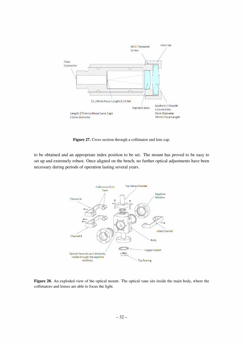
Figure 27. Cross section through a collimator and lens cap.
to be obtained and an appropriate index position to be set. The mount has proved to be easy toset up and extremely robust. Once aligned on the bench, no further optical adjustments have beennecessary during periods of operation lasting several years.
Figure 28. An exploded view of the optical mount. The optical vane sits inside the main body, where thecollimators and lenses are able to focus the light.
– 32 –
5.5 Optical sensors
The multimode fibres are returned to an SMA photodiode (H3R880IR)[19]. This is a broad spec-trum photodiode (400 to 1100 nm). As the maximum velocity of the target is less than 10 m s−1,the maximum data rate per channel is only 33 kHz, well within the response capability of thesedevices. The outputs from the photodiodes are amplified and conditioned before being convertedinto digital signals.
6. Stator operation and power electronics
6.1 Introduction
The target drive is a three-phase, brush-less, permanent-magnet DC linear motor. Before consider-ing how the force on the magnetic assembly changes with respect to its position within a poweredcoil stack, it is necessary to understand how the coils in the stator are wired and how they areswitched.
The 24 coils in the stator are split into three phases A, B and C, with eight coils in each phase.Starting from the top of the coil stack (see figure 29), the coils are lettered in a cyclic sequence thatfollows the pattern, A B′ C A′ B C′. A block of six coils labelled in this way is called a “bank”.This sequence is repeated four times so there are four banks of coils in the target stator, as shownin figure 29. All the A and A′ coils are wired together in series, as are the B and B′ coils and theC and C′ coils. The unprimed and primed coils are wired such that when a current passes througheither an A, B or C coil in a clockwise direction, the same current passes through an A′, B′ or C′ coilin an anticlockwise direction. The induced magnetic field direction for a primed coil is thereforeopposite to that of an unprimed coil. There are two connections for each phase, one at the topof the stack and one at the bottom. The three separate connections at the bottom of the stack arewired together to form the “star-point”, while the three at the top are connected to the stator powersupply, as shown if figure 30. If current is fed into one of the phases then it must return throughone (or both) of the other phases. Therefore when current flows, at a minimum two phases musthave current passing through them.
6.2 Coil current switching sequence
For the target mechanism, only two of three phases are ever powered at the same time1, i.e. onephase is switched to provide the current source and another phase provides the return path. This op-eration is slightly different from the usual method of driving each phase with a phasor, but reducescomplexity at the cost of only a small reduction in efficiency. With three phases, current can there-fore be switched through the stator in six different ways. Using the external connection labels A,B′ and C as shown in figure 30, these six states are: A→B′, A→C, B′→A, B′→C, C→A and C→B′.By stepping through these six states in a predetermined order, the coils can be switched to create a“ripple” motion in the magnetic fields generated within the stator, as illustrated in figure 31. Thedirection of motion is determined by the direction in which these states are stepped through; whenreversing this order the ripple motion moves in the opposite direction. By tracking the position
1We have recently changed to powering three phases simultaneously.
– 33 –
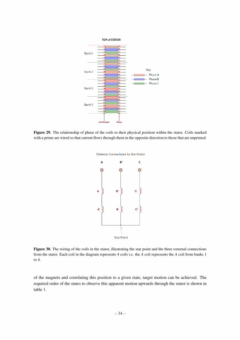
Figure 29. The relationship of phase of the coils to their physical position within the stator. Coils markedwith a prime are wired so that current flows through them in the opposite direction to those that are unprimed.
Figure 30. The wiring of the coils in the stator, illustrating the star point and the three external connectionsfrom the stator. Each coil in the diagram represents 4 coils i.e. the A coil represents the A coil from banks 1to 4.
of the magnets and correlating this position to a given state, target motion can be achieved. Therequired order of the states to observe this apparent motion upwards through the stator is shown intable 1.
– 34 –
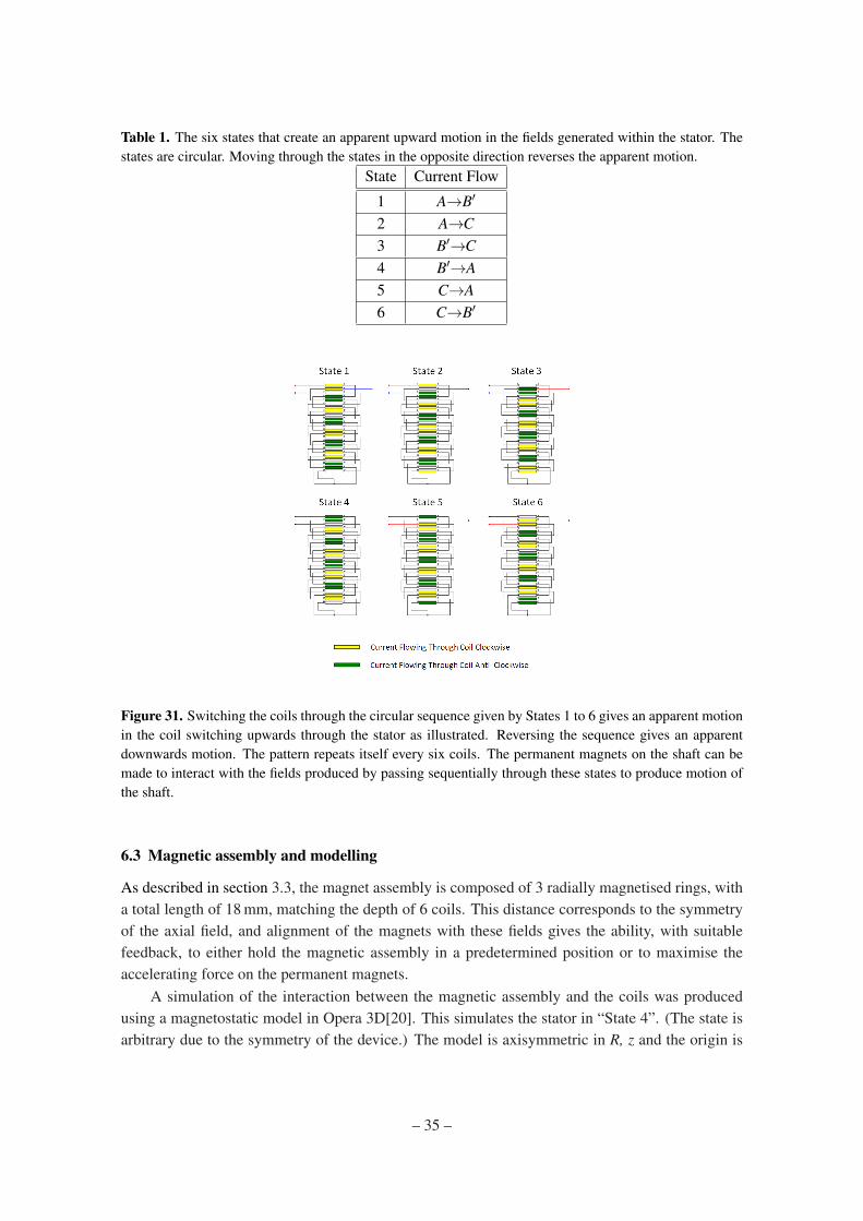
Table 1. The six states that create an apparent upward motion in the fields generated within the stator. Thestates are circular. Moving through the states in the opposite direction reverses the apparent motion.
State Current Flow
1 A→B′
2 A→C3 B′→C4 B′→A5 C→A6 C→B′
Figure 31. Switching the coils through the circular sequence given by States 1 to 6 gives an apparent motionin the coil switching upwards through the stator as illustrated. Reversing the sequence gives an apparentdownwards motion. The pattern repeats itself every six coils. The permanent magnets on the shaft can bemade to interact with the fields produced by passing sequentially through these states to produce motion ofthe shaft.
6.3 Magnetic assembly and modelling
As described in section 3.3, the magnet assembly is composed of 3 radially magnetised rings, witha total length of 18 mm, matching the depth of 6 coils. This distance corresponds to the symmetryof the axial field, and alignment of the magnets with these fields gives the ability, with suitablefeedback, to either hold the magnetic assembly in a predetermined position or to maximise theaccelerating force on the permanent magnets.
A simulation of the interaction between the magnetic assembly and the coils was producedusing a magnetostatic model in Opera 3D[20]. This simulates the stator in “State 4”. (The state isarbitrary due to the symmetry of the device.) The model is axisymmetric in R, z and the origin is
– 35 –
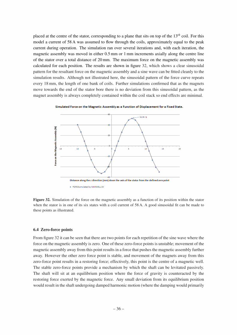
placed at the centre of the stator, corresponding to a plane that sits on top of the 13th coil. For thismodel a current of 58 A was assumed to flow through the coils, approximately equal to the peakcurrent during operation. The simulation ran over several iterations and, with each iteration, themagnetic assembly was moved in either 0.5 mm or 1 mm increments axially along the centre lineof the stator over a total distance of 20 mm. The maximum force on the magnetic assembly wascalculated for each position. The results are shown in figure 32, which shows a clear sinusoidalpattern for the resultant force on the magnetic assembly and a sine wave can be fitted cleanly to thesimulation results. Although not illustrated here, the sinusoidal pattern of the force curve repeatsevery 18 mm, the length of one bank of coils. Further simulations confirmed that as the magnetsmove towards the end of the stator bore there is no deviation from this sinusoidal pattern, as themagnet assembly is always completely contained within the coil stack so end effects are minimal.
Figure 32. Simulation of the force on the magnetic assembly as a function of its position within the statorwhen the stator is in one of its six states with a coil current of 58 A. A good sinusoidal fit can be made tothese points as illustrated.
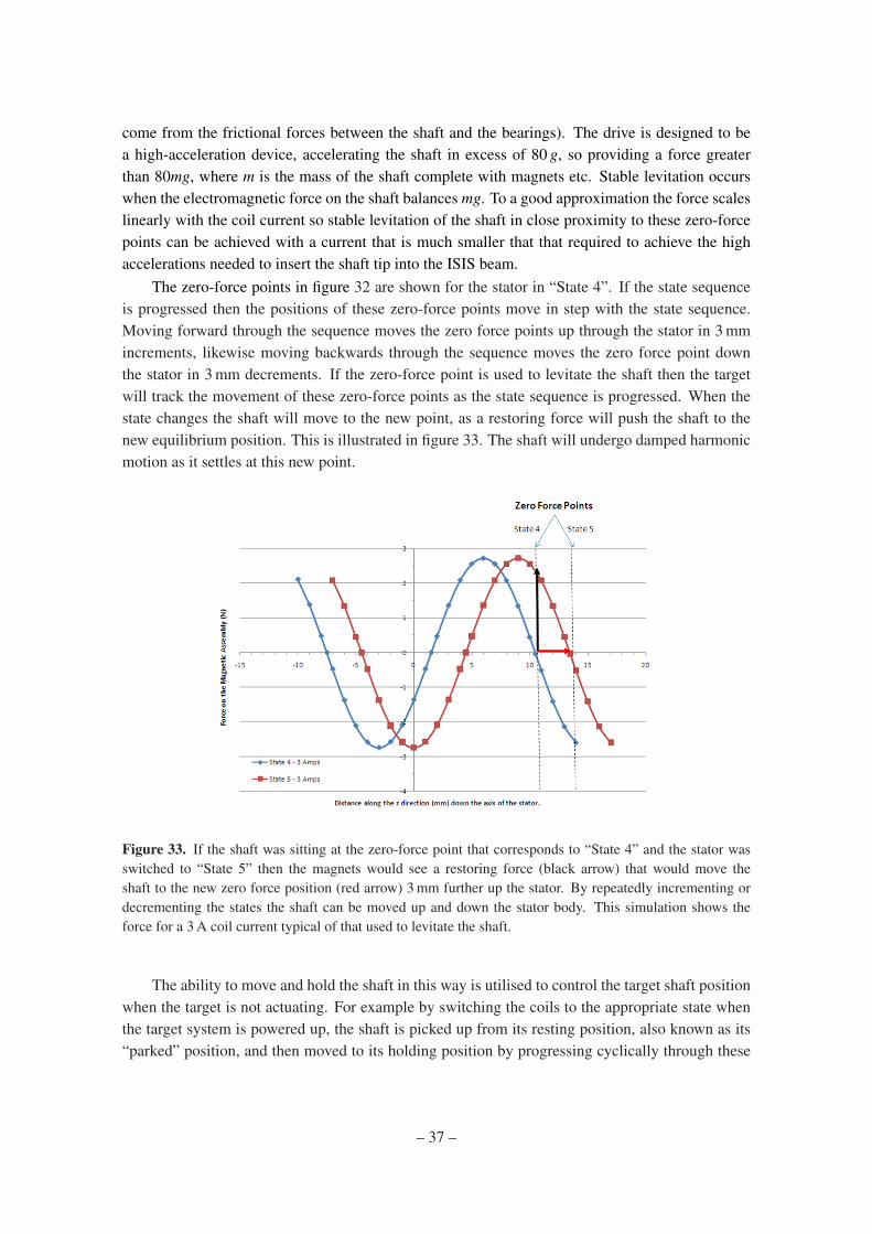
6.4 Zero-force points
From figure 32 it can be seen that there are two points for each repetition of the sine wave where theforce on the magnetic assembly is zero. One of these zero-force points is unstable; movement of themagnetic assembly away from this point results in a force that pushes the magnetic assembly furtheraway. However the other zero force point is stable, and movement of the magnets away from thiszero-force point results in a restoring force; effectively, this point is the centre of a magnetic well.The stable zero-force points provide a mechanism by which the shaft can be levitated passively.The shaft will sit at an equilibrium position where the force of gravity is counteracted by therestoring force exerted by the magnetic force. Any small deviation from its equilibrium positionwould result in the shaft undergoing damped harmonic motion (where the damping would primarily
– 36 –
come from the frictional forces between the shaft and the bearings). The drive is designed to bea high-acceleration device, accelerating the shaft in excess of 80 g, so providing a force greaterthan 80mg, where m is the mass of the shaft complete with magnets etc. Stable levitation occurswhen the electromagnetic force on the shaft balances mg. To a good approximation the force scaleslinearly with the coil current so stable levitation of the shaft in close proximity to these zero-forcepoints can be achieved with a current that is much smaller that that required to achieve the highaccelerations needed to insert the shaft tip into the ISIS beam.
The zero-force points in figure 32 are shown for the stator in “State 4”. If the state sequenceis progressed then the positions of these zero-force points move in step with the state sequence.Moving forward through the sequence moves the zero force points up through the stator in 3 mmincrements, likewise moving backwards through the sequence moves the zero force point downthe stator in 3 mm decrements. If the zero-force point is used to levitate the shaft then the targetwill track the movement of these zero-force points as the state sequence is progressed. When thestate changes the shaft will move to the new point, as a restoring force will push the shaft to thenew equilibrium position. This is illustrated in figure 33. The shaft will undergo damped harmonicmotion as it settles at this new point.
Figure 33. If the shaft was sitting at the zero-force point that corresponds to “State 4” and the stator wasswitched to “State 5” then the magnets would see a restoring force (black arrow) that would move theshaft to the new zero force position (red arrow) 3 mm further up the stator. By repeatedly incrementing ordecrementing the states the shaft can be moved up and down the stator body. This simulation shows theforce for a 3 A coil current typical of that used to levitate the shaft.
The ability to move and hold the shaft in this way is utilised to control the target shaft positionwhen the target is not actuating. For example by switching the coils to the appropriate state whenthe target system is powered up, the shaft is picked up from its resting position, also known as its“parked” position, and then moved to its holding position by progressing cyclically through these
– 37 –

states. This final state, the “hold mode”, then holds the shaft indefinitely until actuation is required.Reversing the process allows the shaft to be lowered back down to its “park-mode”.
Using the stator in this way to control the shaft limits the “hold position” of the shaft to oneof a set of predefined points that are 3 mm apart. This means that the hold position is not entirelyarbitrary, but the 3 mm step size gives enough freedom to ensure that the shaft is held out of theISIS beam. This system of moving the target shaft by allowing the magnets to track the position ofthe zero-force points is entirely passive and does not require any positional feedback to operate.
6.5 Actuation
From figure 32 it can be seen that the zero-force point is half way between two maximum-forcepoints; we define a maximum-force point as a position within the coil stack where the magnetson the shaft would experience a maximal repulsive force. For each set of two maximum-forcepoints, one of them will push the magnets in one direction whilst the other will push the magnets inthe opposite direction. Figure 32 shows that these maximum-force points are positioned ±4.5 mmaway from the zero-force points; this is of course true for any zero-force point in any one of the sixpossible states. It can be seen that the forces change very little ±1.5 mm either side of the peak.Integration of the fitted sine wave ±1.5 mm either side of the peak shows that the average force is95.5% of the peak force. If the shaft was levitated at a zero-force point and the coil state was eitherto increment or to decrement by two states this would put the magnets 1.5 mm on the far side ofone of the maximum-force points as the zero-force point would have been moved by 6 mm. Theshaft would then accelerate back towards the shifted zero-force point. In either case the resultantforce would cause the shaft to pass through the location of the maximum-force point during thefirst 3 mm of acceleration, as illustrated in figure 34.
If, after switching the coil two states, no further switching was done the shaft would continueto accelerate towards the new zero force point 6 mm further up or down the coil stack and wouldexecute damped harmonic motion about this point until it came to rest. However because theposition of the shaft can be tracked using the optical quadrature system, another state change canbe made when the target has travelled 3 mm, placing the magnets 1.5 mm on the far side of the nextmaximum-force point. This has the effect of maintaining a maximal accelerating force on the shaft.This process can be continued down the entire length of the coil stack as illustrated in figure 35. Ifthe shaft is accelerated via this mechanism, deceleration can be achieved by switching the coil stateby three positions. This has the effect of placing a force of equal magnitude but opposite directionon the permanent magnets. Once again, by referring to figure 32 and comparing this to figure 31,it can be seen that a switch of three states changes the direction of the accelerating force because itsimply reverses the current flow through the coils. If a previously accelerated shaft is deceleratedby this process then there will be a point where the shaft will change its direction of motion.
By monitoring the sense in which the position reading is changing, the quadrature system isable to determine the direction of motion of the shaft. A reversal of direction can be used as atrigger to capture the shaft at the nearest zero-force point at the end of an actuation. This is doneby switching to a state that places a zero-force point close to the magnet’s current position. Thecoil pitch of 3 mm dictates that the shaft will never be more than 1.5 mm away from a possiblezero-force point and so, providing the shaft does not have a high velocity, capture of the shaft atthe zero-force point is inevitable.
– 38 –
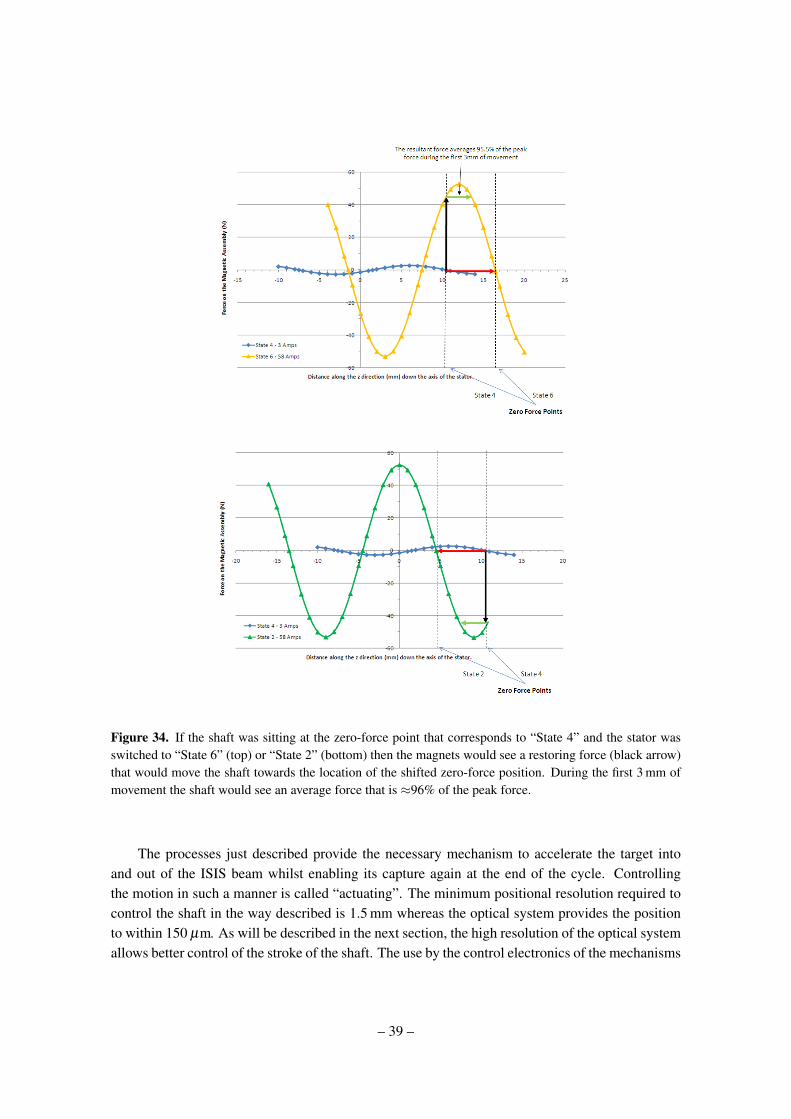
Figure 34. If the shaft was sitting at the zero-force point that corresponds to “State 4” and the stator wasswitched to “State 6” (top) or “State 2” (bottom) then the magnets would see a restoring force (black arrow)that would move the shaft towards the location of the shifted zero-force position. During the first 3 mm ofmovement the shaft would see an average force that is ≈96% of the peak force.
The processes just described provide the necessary mechanism to accelerate the target intoand out of the ISIS beam whilst enabling its capture again at the end of the cycle. Controllingthe motion in such a manner is called “actuating”. The minimum positional resolution required tocontrol the shaft in the way described is 1.5 mm whereas the optical system provides the positionto within 150 µm. As will be described in the next section, the high resolution of the optical systemallows better control of the stroke of the shaft. The use by the control electronics of the mechanisms
– 39 –
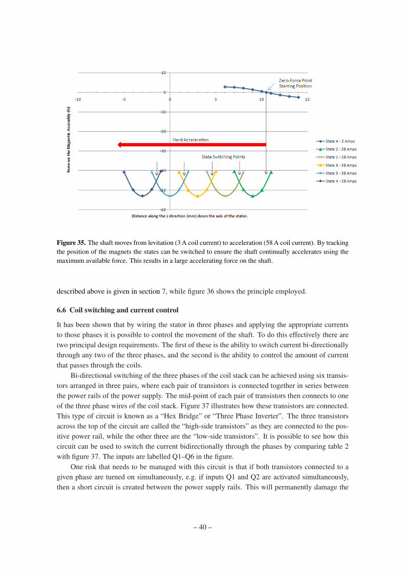
Figure 35. The shaft moves from levitation (3 A coil current) to acceleration (58 A coil current). By trackingthe position of the magnets the states can be switched to ensure the shaft continually accelerates using themaximum available force. This results in a large accelerating force on the shaft.
described above is given in section 7, while figure 36 shows the principle employed.
6.6 Coil switching and current control
It has been shown that by wiring the stator in three phases and applying the appropriate currentsto those phases it is possible to control the movement of the shaft. To do this effectively there aretwo principal design requirements. The first of these is the ability to switch current bi-directionallythrough any two of the three phases, and the second is the ability to control the amount of currentthat passes through the coils.
Bi-directional switching of the three phases of the coil stack can be achieved using six transis-tors arranged in three pairs, where each pair of transistors is connected together in series betweenthe power rails of the power supply. The mid-point of each pair of transistors then connects to oneof the three phase wires of the coil stack. Figure 37 illustrates how these transistors are connected.This type of circuit is known as a “Hex Bridge” or “Three Phase Inverter”. The three transistorsacross the top of the circuit are called the “high-side transistors” as they are connected to the pos-itive power rail, while the other three are the “low-side transistors”. It is possible to see how thiscircuit can be used to switch the current bidirectionally through the phases by comparing table 2with figure 37. The inputs are labelled Q1–Q6 in the figure.
One risk that needs to be managed with this circuit is that if both transistors connected to agiven phase are turned on simultaneously, e.g. if inputs Q1 and Q2 are activated simultaneously,then a short circuit is created between the power supply rails. This will permanently damage the
– 40 –
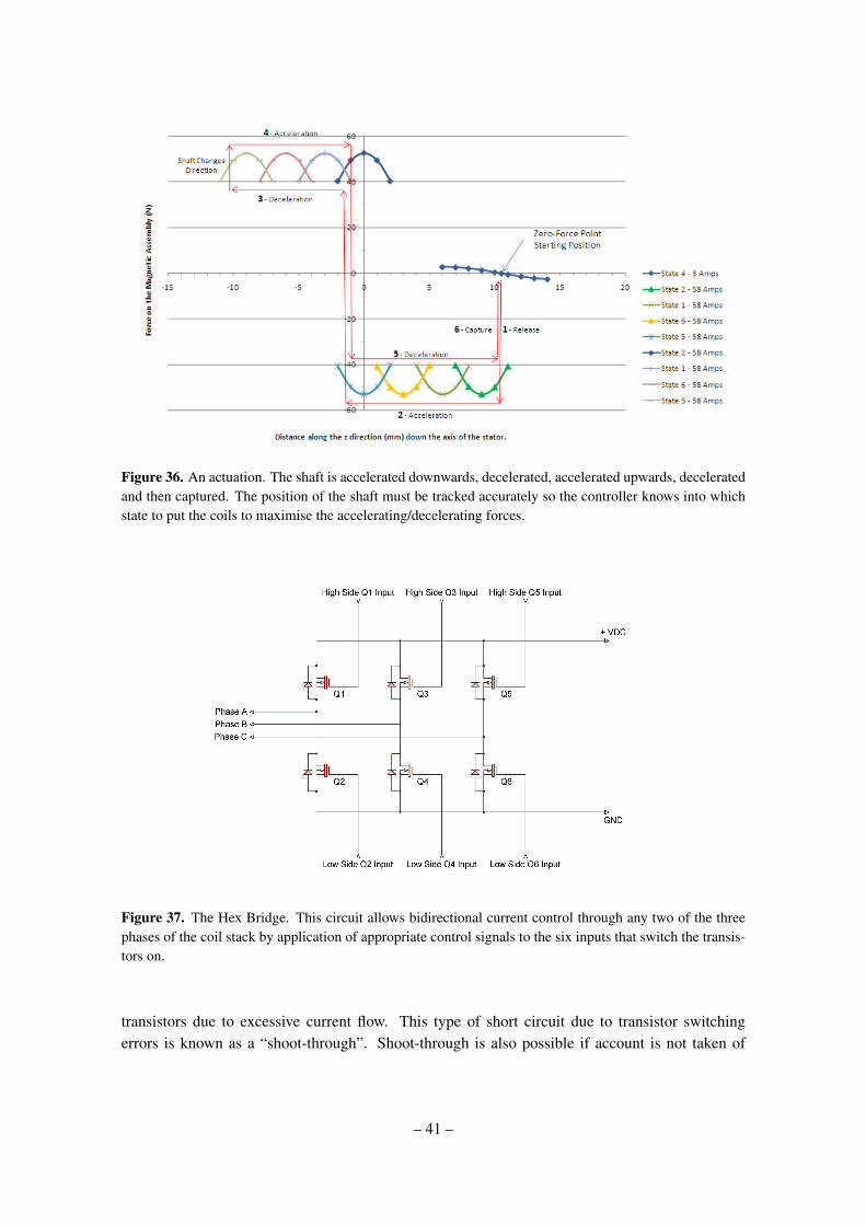
Figure 36. An actuation. The shaft is accelerated downwards, decelerated, accelerated upwards, deceleratedand then captured. The position of the shaft must be tracked accurately so the controller knows into whichstate to put the coils to maximise the accelerating/decelerating forces.
Figure 37. The Hex Bridge. This circuit allows bidirectional current control through any two of the threephases of the coil stack by application of appropriate control signals to the six inputs that switch the transis-tors on.
transistors due to excessive current flow. This type of short circuit due to transistor switchingerrors is known as a “shoot-through”. Shoot-through is also possible if account is not taken of
– 41 –
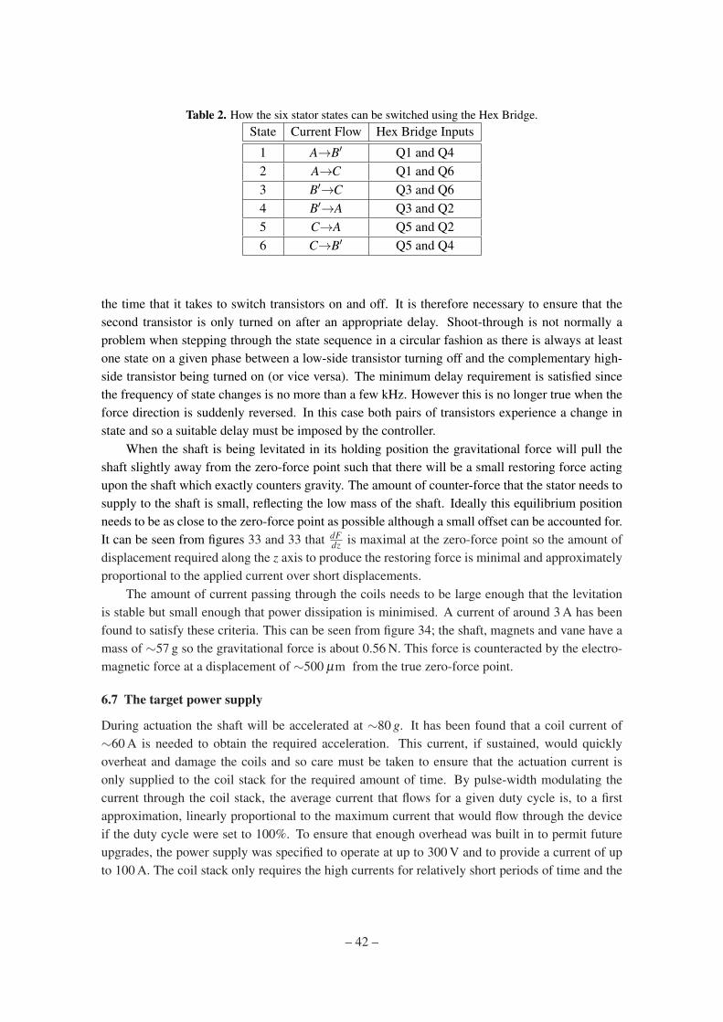
Table 2. How the six stator states can be switched using the Hex Bridge.State Current Flow Hex Bridge Inputs
1 A→B′ Q1 and Q42 A→C Q1 and Q63 B′→C Q3 and Q64 B′→A Q3 and Q25 C→A Q5 and Q26 C→B′ Q5 and Q4
the time that it takes to switch transistors on and off. It is therefore necessary to ensure that thesecond transistor is only turned on after an appropriate delay. Shoot-through is not normally aproblem when stepping through the state sequence in a circular fashion as there is always at leastone state on a given phase between a low-side transistor turning off and the complementary high-side transistor being turned on (or vice versa). The minimum delay requirement is satisfied sincethe frequency of state changes is no more than a few kHz. However this is no longer true when theforce direction is suddenly reversed. In this case both pairs of transistors experience a change instate and so a suitable delay must be imposed by the controller.
When the shaft is being levitated in its holding position the gravitational force will pull theshaft slightly away from the zero-force point such that there will be a small restoring force actingupon the shaft which exactly counters gravity. The amount of counter-force that the stator needs tosupply to the shaft is small, reflecting the low mass of the shaft. Ideally this equilibrium positionneeds to be as close to the zero-force point as possible although a small offset can be accounted for.It can be seen from figures 33 and 33 that dF
dz is maximal at the zero-force point so the amount ofdisplacement required along the z axis to produce the restoring force is minimal and approximatelyproportional to the applied current over short displacements.
The amount of current passing through the coils needs to be large enough that the levitationis stable but small enough that power dissipation is minimised. A current of around 3 A has beenfound to satisfy these criteria. This can be seen from figure 34; the shaft, magnets and vane have amass of ∼57 g so the gravitational force is about 0.56 N. This force is counteracted by the electro-magnetic force at a displacement of ∼500 µm from the true zero-force point.
6.7 The target power supply
During actuation the shaft will be accelerated at ∼80 g. It has been found that a coil current of∼60 A is needed to obtain the required acceleration. This current, if sustained, would quicklyoverheat and damage the coils and so care must be taken to ensure that the actuation current isonly supplied to the coil stack for the required amount of time. By pulse-width modulating thecurrent through the coil stack, the average current that flows for a given duty cycle is, to a firstapproximation, linearly proportional to the maximum current that would flow through the deviceif the duty cycle were set to 100%. To ensure that enough overhead was built in to permit futureupgrades, the power supply was specified to operate at up to 300 V and to provide a current of upto 100 A. The coil stack only requires the high currents for relatively short periods of time and the
– 42 –

average current drawn is significantly lower than the peak current. It is therefore more economicaland efficient to power the driving circuit from a capacitor bank which can provide the short, high-current pulses on demand. The capacitor bank is charged by an external power supply, designed toprovide both the necessary charging current to top the capacitor bank up and the holding current.This capacitor charging unit or CCU effectively provides the average current that the stator uses,whilst the capacitor bank is there to provide the peak currents when required. The size of thecapacitor bank attached to the hex-bridge is 70 mF and is rated to 400 VDC.
The use of a capacitor bank is inherently safer than a linear power supply because, should afault occur that leaves the system in a state that demands high current, once the capacitor bankhas discharged the current is limited to that provided by the CCU. The CCU used only provides acurrent of 4 A, and into a 3.6 Ω load (the DC resistance of two phases of the stator at 20C) thisgives a power dissipation of only ∼60 W. This is significantly lower than the power dissipationduring normal operation when actuating at 1 Hz and so limits the energy deposition into the coilstack. At 70 mF the capacitor bank stores a significant amount of energy. This energy could bedeposited into either the coil stack or the bridge circuit under a fault condition. In order to reducethe voltage between any part of the coil stack and ground, a split supply providing −115 V and+115 V is used (rather than 0 V and +230 V). This necessitates the use of two separate capacitorbanks.
To switch the high currents necessary to drive the target drive, Integrated Gate Bipolar Tran-sistors (IGBTs) are used. These transistors switch current quickly and saturate very close to thepower-supply rail voltage due to a small internal resistance (RON). Both of these characteristics aregood for minimising power dissipation within the transistors making them very efficient at trans-ferring power to the load. By using these transistors a circuit that can switch a significant amountof power can be built with minimum footprint. The IGBTs that were chosen for the target powersupply are power devices and can switch up to 250 A. All six sections of the gate drivers (one foreach IGBT) are taken to a floating DC power supply as this gives better protection to the individ-ual circuits. The logic circuitry that drives the gates on the IGBTs is supplied with power from aseparate supply that is integral to the unit. Each of the two capacitor charging units uses a Xantrex300-4, which can supply up to 4 A at up to 300 V.
Snubber circuitry has been added to the power supply to damp the high frequency transientscreated by the pulsed switching of the transistors. This also helps to stabilise the current flowthrough the motor and reduces electromagnetic noise emitted by the motor, its power supply cableand the driving circuitry.
6.8 System placement in ISIS
The power supply cannot be close to the target mechanism as the radiation produced by ISISwould be likely to cause premature failure of the electronics. It is also advantageous to have theelectronics accessible so that power supply maintenance can be performed without having to waitfor the synchrotron to be opened. The high currents required by the target mechanism and its lowimpedance mean that the distance to the power supply should be minimised to reduce ohmic lossesin the power cable connecting the two together. For this reason the power supply has been installedon the outside wall of the synchrotron at a location as close to the target area as possible, requiringa cable length of 25 m. The control electronics for the target system are situated in the MICE Local
– 43 –
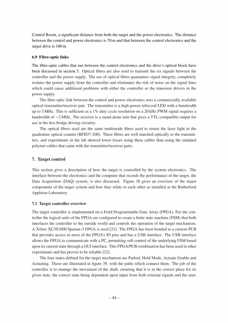
Control Room, a significant distance from both the target and the power electronics. The distancebetween the control and power electronics is 70 m and that between the control electronics and thetarget drive is 100 m.
6.9 Fibre-optic links
The fibre-optic cables that run between the control electronics and the drive’s optical block havebeen discussed in section 5. Optical fibres are also used to transmit the six signals between thecontroller and the power supply. The use of optical fibres guarantees signal integrity, completelyisolates the power supply from the controller and eliminates the risk of noise on the signal lineswhich could cause additional problems with either the controller or the transistor drivers in thepower supply.
The fibre-optic link between the control and power electronics uses a commercially availableoptical transmitter/receiver pair. The transmitter is a high-power infra-red LED with a bandwidthup to 5 MHz. This is sufficient as a 1% duty cycle resolution on a 20 kHz PWM signal requires abandwidth of ∼2 MHz. The receiver is a stand-alone unit that gives a TTL-compatible output foruse in the hex-bridge driving circuitry.
The optical fibres used are the same multimode fibres used to return the laser light in thequadrature optical counter (BFH37-200). These fibres are well matched optically to the transmit-ters, and experiments in the lab showed lower losses using these cables than using the standardpolymer cables that came with the transmitter/receiver pairs.
7. Target control
This section gives a description of how the target is controlled by the system electronics. Theinterface between the electronics and the computer that records the performance of the target, theData Acquisition (DAQ) system, is also discussed. Figure 38 gives an overview of the majorcomponents of the target system and how they relate to each other as installed at the RutherfordAppleton Laboratory.
7.1 Target controller overview
The target controller is implemented on a Field Programmable Gate Array (FPGA). For the con-troller the logical units of the FPGA are configured to create a finite state machine (FSM) that bothinterfaces the controller to the outside world and controls the operation of the target mechanism.A Xilinx XC3S1000 Spartan-3 FPGA is used [21]. The FPGA has been bonded to a custom PCBthat provides access to most of the FPGA’s IO pins and has a USB interface. The USB interfaceallows the FPGA to communicate with a PC, permitting soft control of the underlying FSM basedupon its current state through a GUI interface. This FPGA/PCB combination has been used in otherexperiments and has proven to be reliable [22].
The four states defined for the target mechanism are Parked, Hold Mode, Actuate Enable andActuating. These are illustrated in figure 39, with the paths which connect them. The job of thecontroller is to manage the movement of the shaft, ensuring that it is in the correct place for itsgiven state, the correct state being dependent upon input from both external signals and the user.
– 44 –
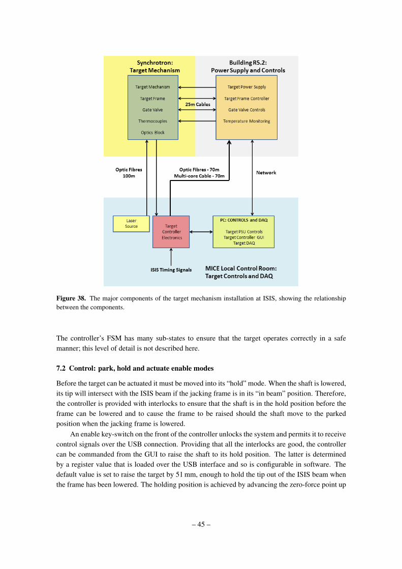
Figure 38. The major components of the target mechanism installation at ISIS, showing the relationshipbetween the components.
The controller’s FSM has many sub-states to ensure that the target operates correctly in a safemanner; this level of detail is not described here.
7.2 Control: park, hold and actuate enable modes
Before the target can be actuated it must be moved into its “hold” mode. When the shaft is lowered,its tip will intersect with the ISIS beam if the jacking frame is in its “in beam” position. Therefore,the controller is provided with interlocks to ensure that the shaft is in the hold position before theframe can be lowered and to cause the frame to be raised should the shaft move to the parkedposition when the jacking frame is lowered.
An enable key-switch on the front of the controller unlocks the system and permits it to receivecontrol signals over the USB connection. Providing that all the interlocks are good, the controllercan be commanded from the GUI to raise the shaft to its hold position. The latter is determinedby a register value that is loaded over the USB interface and so is configurable in software. Thedefault value is set to raise the target by 51 mm, enough to hold the tip out of the ISIS beam whenthe frame has been lowered. The holding position is achieved by advancing the zero-force point up
– 45 –
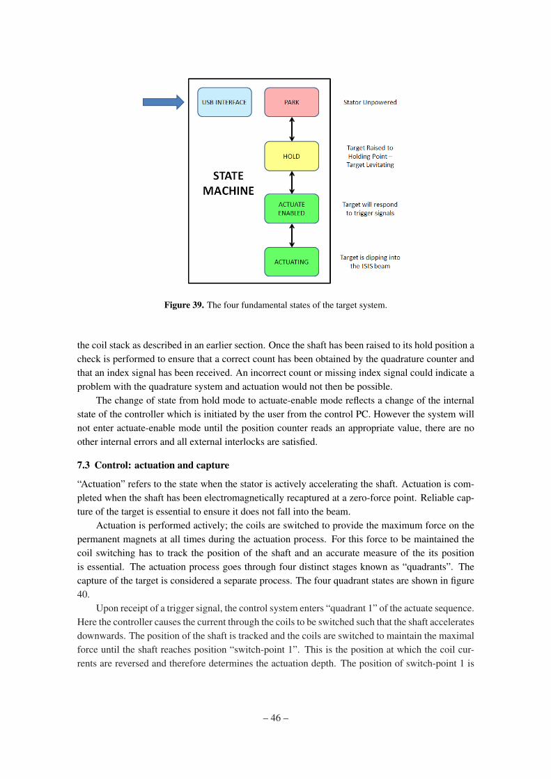
Figure 39. The four fundamental states of the target system.
the coil stack as described in an earlier section. Once the shaft has been raised to its hold position acheck is performed to ensure that a correct count has been obtained by the quadrature counter andthat an index signal has been received. An incorrect count or missing index signal could indicate aproblem with the quadrature system and actuation would not then be possible.
The change of state from hold mode to actuate-enable mode reflects a change of the internalstate of the controller which is initiated by the user from the control PC. However the system willnot enter actuate-enable mode until the position counter reads an appropriate value, there are noother internal errors and all external interlocks are satisfied.
7.3 Control: actuation and capture
“Actuation” refers to the state when the stator is actively accelerating the shaft. Actuation is com-pleted when the shaft has been electromagnetically recaptured at a zero-force point. Reliable cap-ture of the target is essential to ensure it does not fall into the beam.
Actuation is performed actively; the coils are switched to provide the maximum force on thepermanent magnets at all times during the actuation process. For this force to be maintained thecoil switching has to track the position of the shaft and an accurate measure of the its positionis essential. The actuation process goes through four distinct stages known as “quadrants”. Thecapture of the target is considered a separate process. The four quadrant states are shown in figure40.
Upon receipt of a trigger signal, the control system enters “quadrant 1” of the actuate sequence.Here the controller causes the current through the coils to be switched such that the shaft acceleratesdownwards. The position of the shaft is tracked and the coils are switched to maintain the maximalforce until the shaft reaches position “switch-point 1”. This is the position at which the coil cur-rents are reversed and therefore determines the actuation depth. The position of switch-point 1 is
– 46 –
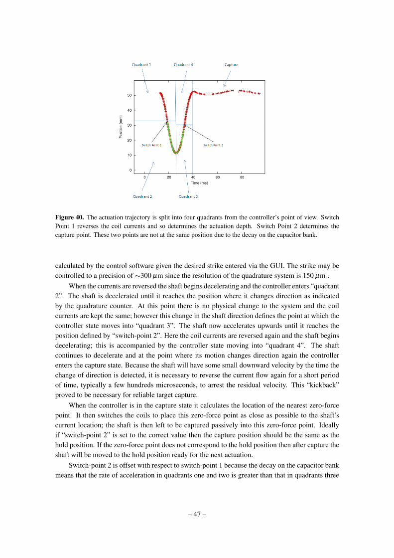
Figure 40. The actuation trajectory is split into four quadrants from the controller’s point of view. SwitchPoint 1 reverses the coil currents and so determines the actuation depth. Switch Point 2 determines thecapture point. These two points are not at the same position due to the decay on the capacitor bank.
calculated by the control software given the desired strike entered via the GUI. The strike may becontrolled to a precision of ∼300 µm since the resolution of the quadrature system is 150 µm .
When the currents are reversed the shaft begins decelerating and the controller enters “quadrant2”. The shaft is decelerated until it reaches the position where it changes direction as indicatedby the quadrature counter. At this point there is no physical change to the system and the coilcurrents are kept the same; however this change in the shaft direction defines the point at which thecontroller state moves into “quadrant 3”. The shaft now accelerates upwards until it reaches theposition defined by “switch-point 2”. Here the coil currents are reversed again and the shaft beginsdecelerating; this is accompanied by the controller state moving into “quadrant 4”. The shaftcontinues to decelerate and at the point where its motion changes direction again the controllerenters the capture state. Because the shaft will have some small downward velocity by the time thechange of direction is detected, it is necessary to reverse the current flow again for a short periodof time, typically a few hundreds microseconds, to arrest the residual velocity. This “kickback”proved to be necessary for reliable target capture.
When the controller is in the capture state it calculates the location of the nearest zero-forcepoint. It then switches the coils to place this zero-force point as close as possible to the shaft’scurrent location; the shaft is then left to be captured passively into this zero-force point. Ideallyif “switch-point 2” is set to the correct value then the capture position should be the same as thehold position. If the zero-force point does not correspond to the hold position then after capture theshaft will be moved to the hold position ready for the next actuation.
Switch-point 2 is offset with respect to switch-point 1 because the decay on the capacitor bankmeans that the rate of acceleration in quadrants one and two is greater than that in quadrants three
– 47 –
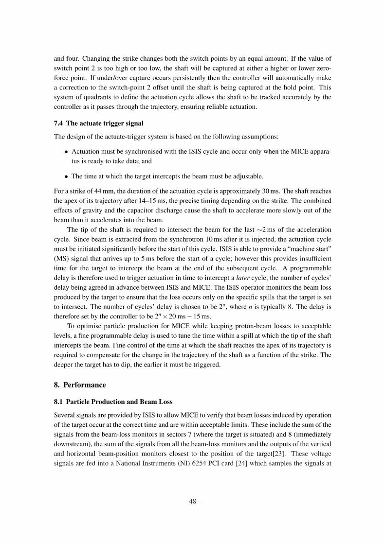
and four. Changing the strike changes both the switch points by an equal amount. If the value ofswitch point 2 is too high or too low, the shaft will be captured at either a higher or lower zero-force point. If under/over capture occurs persistently then the controller will automatically makea correction to the switch-point 2 offset until the shaft is being captured at the hold point. Thissystem of quadrants to define the actuation cycle allows the shaft to be tracked accurately by thecontroller as it passes through the trajectory, ensuring reliable actuation.
7.4 The actuate trigger signal
The design of the actuate-trigger system is based on the following assumptions:
• Actuation must be synchronised with the ISIS cycle and occur only when the MICE appara-tus is ready to take data; and
• The time at which the target intercepts the beam must be adjustable.
For a strike of 44 mm, the duration of the actuation cycle is approximately 30 ms. The shaft reachesthe apex of its trajectory after 14–15 ms, the precise timing depending on the strike. The combinedeffects of gravity and the capacitor discharge cause the shaft to accelerate more slowly out of thebeam than it accelerates into the beam.
The tip of the shaft is required to intersect the beam for the last ∼2 ms of the accelerationcycle. Since beam is extracted from the synchrotron 10 ms after it is injected, the actuation cyclemust be initiated significantly before the start of this cycle. ISIS is able to provide a “machine start”(MS) signal that arrives up to 5 ms before the start of a cycle; however this provides insufficienttime for the target to intercept the beam at the end of the subsequent cycle. A programmabledelay is therefore used to trigger actuation in time to intercept a later cycle, the number of cycles’delay being agreed in advance between ISIS and MICE. The ISIS operator monitors the beam lossproduced by the target to ensure that the loss occurs only on the specific spills that the target is setto intersect. The number of cycles’ delay is chosen to be 2n, where n is typically 8. The delay istherefore set by the controller to be 2n×20 ms−15 ms.
To optimise particle production for MICE while keeping proton-beam losses to acceptablelevels, a fine programmable delay is used to tune the time within a spill at which the tip of the shaftintercepts the beam. Fine control of the time at which the shaft reaches the apex of its trajectory isrequired to compensate for the change in the trajectory of the shaft as a function of the strike. Thedeeper the target has to dip, the earlier it must be triggered.
8. Performance
8.1 Particle Production and Beam Loss
Several signals are provided by ISIS to allow MICE to verify that beam losses induced by operationof the target occur at the correct time and are within acceptable limits. These include the sum of thesignals from the beam-loss monitors in sectors 7 (where the target is situated) and 8 (immediatelydownstream), the sum of the signals from all the beam-loss monitors and the outputs of the verticaland horizontal beam-position monitors closest to the position of the target[23]. These voltagesignals are fed into a National Instruments (NI) 6254 PCI card [24] which samples the signals at
– 48 –
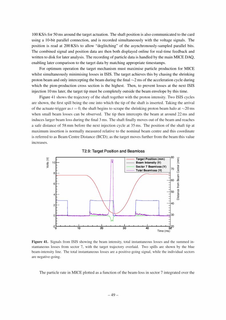
100 KS/s for 50 ms around the target actuation. The shaft position is also communicated to the cardusing a 10-bit parallel connection, and is recorded simultaneously with the voltage signals. Theposition is read at 200 KS/s to allow “deglitching” of the asynchronously-sampled parallel bits.The combined signal and position data are then both displayed online for real-time feedback andwritten to disk for later analysis. The recording of particle data is handled by the main MICE DAQ,enabling later comparison to the target data by matching appropriate timestamps.
For optimum operation the target mechanism must maximise particle production for MICEwhilst simultaneously minimising losses in ISIS. The target achieves this by chasing the shrinkingproton beam and only intercepting the beam during the final∼2 ms of the acceleration cycle duringwhich the pion-production cross section is the highest. Then, to prevent losses at the next ISISinjection 10 ms later, the target tip must be completely outside the beam envelope by this time.
Figure 41 shows the trajectory of the shaft together with the proton intensity. Two ISIS cyclesare shown, the first spill being the one into which the tip of the shaft is inserted. Taking the arrivalof the actuate-trigger as t = 0, the shaft begins to scrape the shrinking proton beam halo at ∼20 mswhen small beam losses can be observed. The tip then intercepts the beam at around 22 ms andinduces larger beam loss during the final 3 ms. The shaft finally moves out of the beam and reachesa safe distance of 58 mm before the next injection cycle at 35 ms. The position of the shaft tip atmaximum insertion is normally measured relative to the nominal beam centre and this coordinateis referred to as Beam Centre Distance (BCD); as the target moves further from the beam this valueincreases.
Figure 41. Signals from ISIS showing the beam intensity, total instantaneous losses and the summed in-stantaneous losses from sector 7, with the target trajectory overlaid. Two spills are shown by the bluebeam-intensity line. The total instantaneous losses are a positive-going signal, while the individual sectorsare negative-going.
The particle rate in MICE plotted as a function of the beam-loss in sector 7 integrated over the
– 49 –
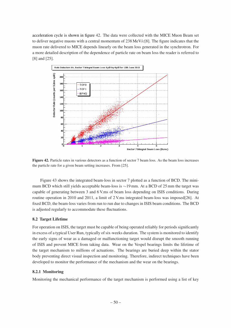
acceleration cycle is shown in figure 42. The data were collected with the MICE Muon Beam setto deliver negative muons with a central momentum of 238 MeV/c[8]. The figure indicates that themuon rate delivered to MICE depends linearly on the beam loss generated in the synchrotron. Fora more detailed description of the dependence of particle rate on beam loss the reader is referred to[8] and [25].
Figure 42. Particle rates in various detectors as a function of sector 7 beam loss. As the beam loss increasesthe particle rate for a given beam setting increases. From [25].
Figure 43 shows the integrated beam-loss in sector 7 plotted as a function of BCD. The mini-mum BCD which still yields acceptable beam-loss is ∼19 mm. At a BCD of 25 mm the target wascapable of generating between 3 and 6 V.ms of beam loss depending on ISIS conditions. Duringroutine operation in 2010 and 2011, a limit of 2 V.ms integrated beam-loss was imposed[26]. Atfixed BCD, the beam-loss varies from run to run due to changes in ISIS beam conditions. The BCDis adjusted regularly to accommodate these fluctuations.
8.2 Target Lifetime
For operation on ISIS, the target must be capable of being operated reliably for periods significantlyin excess of a typical User Run, typically of six-weeks duration. The system is monitored to identifythe early signs of wear as a damaged or malfunctioning target would disrupt the smooth runningof ISIS and prevent MICE from taking data. Wear on the Vespel bearings limits the lifetime ofthe target mechanism to millions of actuations. The bearings are buried deep within the statorbody preventing direct visual inspection and monitoring. Therefore, indirect techniques have beendeveloped to monitor the performance of the mechanism and the wear on the bearings.
8.2.1 Monitoring
Monitoring the mechanical performance of the target mechanism is performed using a list of key
– 50 –
Target Beam Centre Distance (mm)
26 28 30 32 34 36 38
Sec
tor
7 I
nte
gra
l B
eam
Lo
ss
(V
.ms
)
1
2
3
4
5
6
6th November 2009
15th June 2010
16th June 2010
14th August 2010
Sector 7 Integral Beam Loss Vs. Target Depth
Figure 43. Beam loss as a function of target depth. While the target is capable of generating in excess of6 V.ms of beam loss, the limits set by ISIS for regular running are normally 2 V.ms. From [25].
values returned from the controller after each actuation. This list includes data from the actuation,such as the time to reach switch-point 1, the minimum position reached and any errors whichoccurred. This information is ideal for long-term monitoring because it contains only key values,reducing the volume of data and the processing time. In addition, since the data is calculated bythe control algorithm during actuation it is much more precise and flexible than that collected bythe NI card. The data is analysed offline using a simple ROOT[27] script to study the variation inperformance as a function of time.
8.2.2 Bearing Performance
The bearing performance is monitored using two key parameters. The first is the acceleration ofthe shaft, since any increase in friction will also cause a decrease in acceleration. This is calculatedfrom the start of the actuation to the first switch-point (see figure 40), since the velocity of theshaft at this point ensures a good time-resolution. Unfortunately, any change in the voltage ortemperature of the coils also has an effect on the coil current and therefore on the acceleration. Tohelp reduce these effects the capacitors are charged to a fixed voltage (115 V) and the temperatureof the coils is recorded. Figure 44 shows the drop in acceleration over time as the bearings wear.
In addition to decreasing acceleration, the greater friction also allows the shaft and magnetsto be captured and held further from the zero-force point at the centre of the magnetic potential(see section 6.4). This can be observed at the beginning of the next actuation when the shaftposition is displaced from its normal starting location. This effect is monitored over time by plottingthe distribution of starting positions for several hundred actuations and calculating the full width.Figure 45 shows the increase in the full width of the starting position. The increasing jitter onthe starting position also causes variation in the BCD due to the symmetry about set-point 1. An
– 51 –
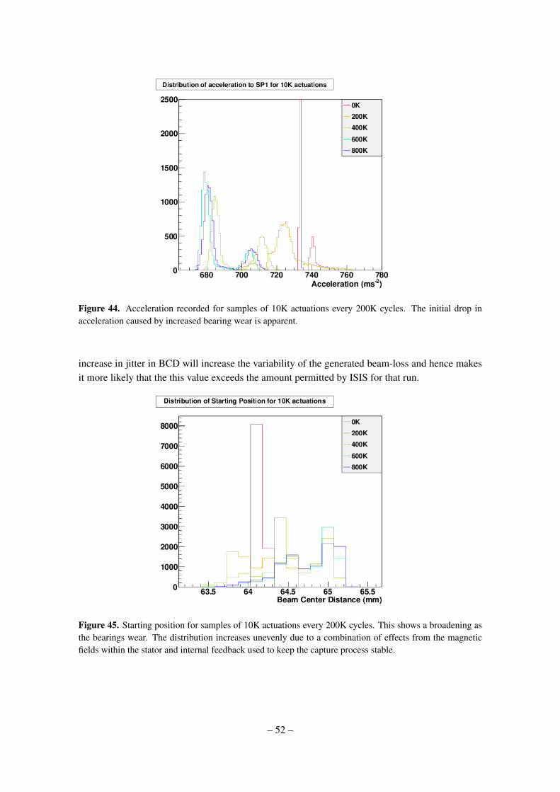
Figure 44. Acceleration recorded for samples of 10K actuations every 200K cycles. The initial drop inacceleration caused by increased bearing wear is apparent.
increase in jitter in BCD will increase the variability of the generated beam-loss and hence makesit more likely that the this value exceeds the amount permitted by ISIS for that run.
Figure 45. Starting position for samples of 10K actuations every 200K cycles. This shows a broadening asthe bearings wear. The distribution increases unevenly due to a combination of effects from the magneticfields within the stator and internal feedback used to keep the capture process stable.
– 52 –

8.2.3 Test Programme
To aid in understand bearing wear, develop monitoring techniques and improve bearing life anextensive test programme has been undertaken. The nomenclature used to identify the target ver-sion is Tn.m, where n corresponds to the stator number and m corresponds to the shaft/bearingcombination. For testing, stator 2 was used, as stator 1 was installed inside ISIS. Each test used afreshly-machined set of VESPEL bearings. For maximum wear, the largest strike of 45 mm (cor-responding to 19 mm BCD) and a high dip rate (0.83 Hz) were used. For comparison, operation inISIS typically runs at rate of 0.4 Hz and with a strike of 36 mm.
Table 3 shows a summary of the bearing tests on stator 2 since the development of the FPGA-based control system. The first system tested was T2.4, which had a fully quality-assured DLC-coated shaft and a set of VESPEL bearings. The test ran for approximately 3 weeks and was disas-sembled at weekly intervals to check for dust. The test was terminated at 1 million actuations whenthe shaft began to lock up due to wear in the anti-rotation component. This was resolved by cuttingsemi-circular reliefs out of the bearing as described in section 4.2.3, which was implemented in thesubsequent test T2.5.
Table 3. Summary of bearing tests, ordered chronologically.
Test Actuations (K) Run Acceptable Commentsmode for ISIS?
T2.4 1,000 WIa Y Well-polished shaft, occasional stickingduring capture (outside ISIS).
T2.5 4,000 WI Y Weekly inspections caused anoticeable disturbance to performance.
T2.6 1,100 DSb Y Tight bearing-clearances. Sticking duringcapture noted at end of run.
T2.7 1,300 DS Y Clearances re-matched to T2.5, minorincrease in time before sticking during capture.
T2.8a 1,000 DS Y Further increase to bearing-clearance, stickingbegan near 1 million actuations. Test paused
for controller update to help alleviate sticking.T2.8b 1,000 + 1,500 DS Y T2.8 test resumed with an updated controller
and enabled a further 1.5 million actuations.
aWeekly Inspection. The target was disassembled on a weekly basis to monitor the dust produced by the bearingwear.
bDaily Stop. Once a day the mechanism is stopped for an hour to let the system cool and thermally contract.
The next test, T2.5, was set up identically to T2.4 and ran for over 8 weeks and 4 millionactuations. Each week the bearings were inspected for dust and a small, but noticeable, amount builtup over time (see figure 46). In the monitoring of acceleration and starting position, a performanceincrease was noticed after the disturbance caused by each inspection. Such disturbance is notpossible in ISIS and the weekly inspections were abandoned in future tests.
– 53 –
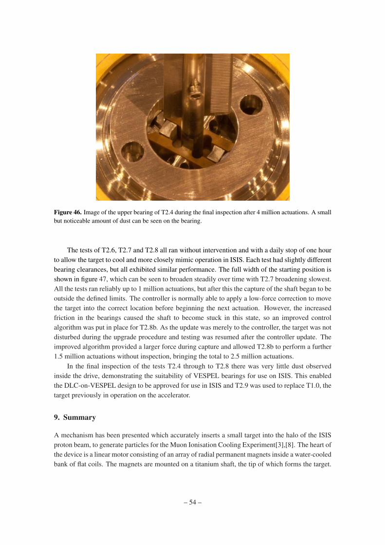
Figure 46. Image of the upper bearing of T2.4 during the final inspection after 4 million actuations. A smallbut noticeable amount of dust can be seen on the bearing.
The tests of T2.6, T2.7 and T2.8 all ran without intervention and with a daily stop of one hourto allow the target to cool and more closely mimic operation in ISIS. Each test had slightly differentbearing clearances, but all exhibited similar performance. The full width of the starting position isshown in figure 47, which can be seen to broaden steadily over time with T2.7 broadening slowest.All the tests ran reliably up to 1 million actuations, but after this the capture of the shaft began to beoutside the defined limits. The controller is normally able to apply a low-force correction to movethe target into the correct location before beginning the next actuation. However, the increasedfriction in the bearings caused the shaft to become stuck in this state, so an improved controlalgorithm was put in place for T2.8b. As the update was merely to the controller, the target was notdisturbed during the upgrade procedure and testing was resumed after the controller update. Theimproved algorithm provided a larger force during capture and allowed T2.8b to perform a further1.5 million actuations without inspection, bringing the total to 2.5 million actuations.
In the final inspection of the tests T2.4 through to T2.8 there was very little dust observedinside the drive, demonstrating the suitability of VESPEL bearings for use on ISIS. This enabledthe DLC-on-VESPEL design to be approved for use in ISIS and T2.9 was used to replace T1.0, thetarget previously in operation on the accelerator.
9. Summary
A mechanism has been presented which accurately inserts a small target into the halo of the ISISproton beam, to generate particles for the Muon Ionisation Cooling Experiment[3],[8]. The heart ofthe device is a linear motor consisting of an array of radial permanent magnets inside a water-cooledbank of flat coils. The magnets are mounted on a titanium shaft, the tip of which forms the target.
– 54 –
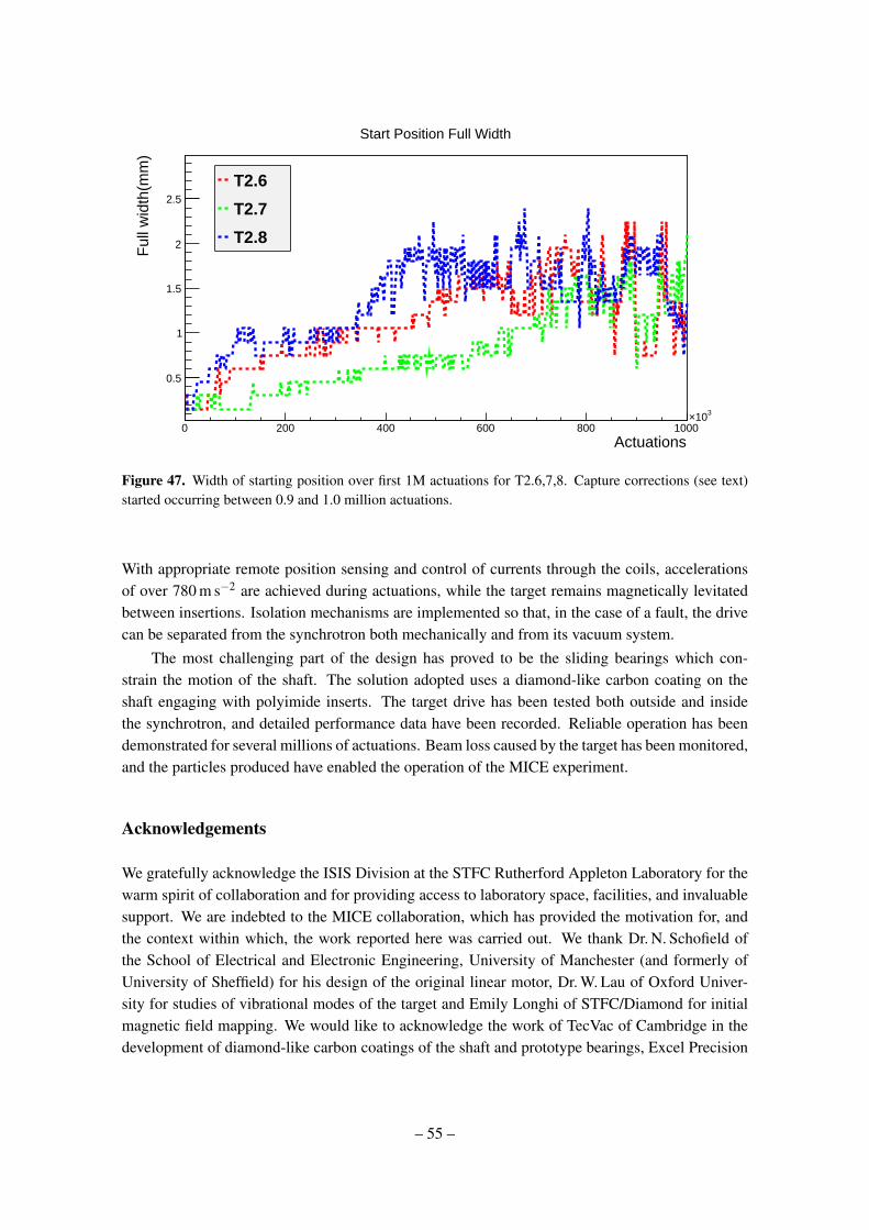
Actuations0 200 400 600 800 1000
310×
Ful
l wid
th(m
m)
0.5
1
1.5
2
2.5
Start Position Full Width
T2.6
T2.7
T2.8
Figure 47. Width of starting position over first 1M actuations for T2.6,7,8. Capture corrections (see text)started occurring between 0.9 and 1.0 million actuations.
With appropriate remote position sensing and control of currents through the coils, accelerationsof over 780 m s−2 are achieved during actuations, while the target remains magnetically levitatedbetween insertions. Isolation mechanisms are implemented so that, in the case of a fault, the drivecan be separated from the synchrotron both mechanically and from its vacuum system.
The most challenging part of the design has proved to be the sliding bearings which con-strain the motion of the shaft. The solution adopted uses a diamond-like carbon coating on theshaft engaging with polyimide inserts. The target drive has been tested both outside and insidethe synchrotron, and detailed performance data have been recorded. Reliable operation has beendemonstrated for several millions of actuations. Beam loss caused by the target has been monitored,and the particles produced have enabled the operation of the MICE experiment.
Acknowledgements
We gratefully acknowledge the ISIS Division at the STFC Rutherford Appleton Laboratory for thewarm spirit of collaboration and for providing access to laboratory space, facilities, and invaluablesupport. We are indebted to the MICE collaboration, which has provided the motivation for, andthe context within which, the work reported here was carried out. We thank Dr. N. Schofield ofthe School of Electrical and Electronic Engineering, University of Manchester (and formerly ofUniversity of Sheffield) for his design of the original linear motor, Dr. W. Lau of Oxford Univer-sity for studies of vibrational modes of the target and Emily Longhi of STFC/Diamond for initialmagnetic field mapping. We would like to acknowledge the work of TecVac of Cambridge in thedevelopment of diamond-like carbon coatings of the shaft and prototype bearings, Excel Precision
– 55 –

of Gloucester for accurate spark erosion of the lower-shaft bore and the apertures in the vane, andMultigrind Services Ltd of Rickmansworth for precise grinding of the upper shafts.
This work was supported by the Science and Technology Facilities Council under grant num-bers PP/E003214/1, PP/E000479/1, PP/E000509/1, PP/E000444/1, and through SLAs with STFC-supported laboratories.
– 56 –

References
[1] S. Geer, Neutrino beams from muon storage rings: Characteristics and physics potential, Phys. Rev.D57 (1998) 6989–6997, [hep-ph/9712290].
[2] D. Neuffer, Multi-Tev muon colliders, AIP Conference Proceedings 156 (1987), no. 1 201–208.
[3] MICE Collaboration, G. Gregoire et al., An International Muon Ionization Cooling Experiment(MICE), MICE Note 167 (2003) [http://mice.iit.edu/mnp/MICE0021.pdf].
[4] “ISIS pulsed neutron & muon source.” http://www.isis.rl.ac.uk/.
[5] Rutherford Appleton Laboratory (RAL).http://www.scitech.ac.uk/About/find/RAL/introduction.aspx/.
[6] MICE Collaboration, “MICE technical reference document - draft version.”http://www.isis.rl.ac.uk/accelerator/mice/TR/MICE_Tech_Ref.html, 2005.
[7] eds. S. Ozaki, R. Palmer, M. Zisman, and J. Gallardo, Feasibility study-II of a muon-based neutrinosource, BNL-52623 (2001) [www.cap.bnl.gov/mumu/studyii/FS2-report.html].
[8] MICE Collaboration, The MICE muon beam on ISIS and the beam-line instrumentation of the MuonIonization Cooling Experiment, JINST 7 (2012) P05009, [1203.4089].
[9] N. Schofield, C. Booth, and P. J. Smith, A low mass, brushless permanent magnet linear actuator forthe ISIS target accelerator, in 50th Annual Conference on Magnetism and Magnetic Materials(MMM05), 2005. (Paper FF-12).
[10] “P.A.R. Insulations and Wires Ltd. Technical data MAGNETEMP CA-200.” http://www.par.gb.com.
[11] “P.A.R. Insulations and Wires Ltd. Technical data DOLPHON-2102.” http://www.par.gb.com.
[12] L. Howlett, “Simulation of radiation levels in the MICE target magnets.” MICE Note 166, 2007.http://mice.iit.edu/micenotes/public/pdf/MICE0166/MICE0166.pdf.
[13] A. Fasso et al., FLUKA: a multi-particle transport code, 2005. CERN-2005-10, INFN/TC-05/11,SLAC-R-773.
[14] DIN 65084:1990 Aerospace; Heat treatment of wrought titanium and titanium alloys.
[15] “Specification for material selection and the cleaning of components for use in the ISIS synchrotronsystems.” Rutherford Appleton Laboratory note ISIS/TS/NS/04.
[16] “Vespel® SCP-5000 polyimide isostatic shapes typical ISO properties.” DuPontTM data sheet.
[17] “630 nm single mode fibre.” ThorlabsTM data sheethttp://www.thorlabs.com/Thorcat/12600/12606-s01.pdf.
[18] “0.37 NA hard polymer-clad multimode fibre.” ThorlabsTM data sheethttp://www.thorlabs.com/Thorcat/12200/12255-s01.pdf.
[19] “H3R880IR - FDH3 housing with FDR880IR pin photodiode.” Farnell data sheethttp://www.farnell.com/datasheets/99561.pdf.
[20] Ansoft, “MAXWELL SV. the student version of MAXWELL 2D.”http://www.ansoft.com/maxwellsv/.
[21] “Xilinx Spartan-3 FPGA.” http://www.xilinx.com/support/documentation/user_guides/ug331.
[22] “The SPiDeR Collaboration, note=https://heplnm061.pp.rl.ac.uk/display/spider/Home/.”
– 57 –

[23] S.Payne et al., Beam diagnostics at ISIS, Proceedings of HB2008 (2008) 466.
[24] “National Instruments 6254 PCI card.” http://sine.ni.com/nips/cds/view/p/lang/en/nid/14126.
[25] A. Dobbs, Particle Rate and Host Accelerator Beam Loss on the MICE Experiment. PhD thesis,Imperial College London, 2011.
[26] MICE Collaboration, D. Adams, R. Edgecock, I. Gardner, and K. Long, Pion measurements with theHEP test beam and implications for MICE, MICE Note 217 (2008)[http://mice.iit.edu/micenotes/public/pdf/MICE0217/MICE0217.pdf].
[27] R. Brun and F. Rademakers, ROOT - an object oriented data analysis framework, ProceedingsAIHENP’96 Workshop, Lausanne, Sep. 1996, Nucl. Inst. & Meth. in Phys. Res. A 389 (1997) 81-86.See also http://root.cern.ch/. (1996).
– 58 –


![[PPT]PowerPoint Presentation - Indico · Web viewVacuum Requirements for Collimators Materials used in the collimators: All materials shall be qualified regarding their outgassing:](https://static.fdocuments.in/doc/165x107/5b3967ab7f8b9ab9068e7e6e/pptpowerpoint-presentation-indico-web-viewvacuum-requirements-for-collimators.jpg)