
The Design and Implementation of a Mobile RFID Tag Sorting...
12
The Design and Implementation of a Mobile RFID Tag Sorting Robot Longfei Shangguan † and Kyle Jamieson †,‡ † Princeton University, ‡ University College London {longfeis, kylej}@cs.princeton.edu ABSTRACT Libraries, manufacturing lines, and offices of the future all stand to benefit from knowing the exact spatial order of RFID-tagged books, components, and folders, respectively. To this end, radio- based localization has demonstrated the potential for high accuracy. Key enabling ideas include motion-based synthetic aperture radar, multipath detection, and the use of different frequencies (channels). But indoors in real-world situations, current systems often fall short of the mark, mainly because of the prevalence and strength of “mul- tipath” reflections of the radio signal off nearby objects. In this pa- per we describe the design and implementation of MobiTagbot, an autonomous wheeled robot reader that conducts a roving survey of the above such areas to achieve an exact spatial order of RFID- tagged objects in very close (1–6 cm) spacings. Our approach leverages a serendipitous correlation between the changes in mul- tipath reflections that occur with motion and the effect of changing the carrier frequency (channel) of the RFID query. By carefully observing the relationship between channel and phase, MobiTagbot detects if multipath is likely prevalent at a given robot reader loca- tion. If so, MobiTagbot excludes phase readings from that reader lo- cation, and generates a final location estimate using phase readings from other locations as the robot reader moves in space. Experi- mentally, we demonstrate that cutting-edge localization algorithms including Tagoram are not accurate enough to exactly order items in very close proximity, but MobiTagbot is, achieving nearly 100% ordering accuracy for items at low (3–6 cm) spacings and 86% ac- curacy for items at very low (1–3 cm) spacings. Keywords Order tracking; RFID; Localization; Multipath propagation 1. INTRODUCTION Radio-based positioning of objects equipped with RFID tags is poised to play a key role in the Internet of Things for libraries, retail business, and next-generation manufacturing: 1. A library patron is frustrated in her search for a misshelved book in her local library. The library has RFID-tagged its stock of books for inventory control and loan tracking and placed RFID ACM ISBN 978-1-4503-2138-9. DOI: 10.1145/1235 RFID tagged docs Moving direction MobiTagbot Figure 1— MobiTagbot roams a building floor, using its RFID an- tennas to scan objects such as these file folders on a bookshelf, checking that their spatial order is correct. readers at the circulation desk, but not in the stacks. Could a RFID-based autonomous robot help locate the misshelved book, or continuously roam the library looking for misshelved books, alerting shelving clerks to the location of any that are found? 2. Supermarkets need to rotate stock as new stock arrives in order to maintain freshness for the consumer. This is highly labor- intensive, requiring the worker to visually inspect the sell-by date of each piece of stock, manually rotate the stock, and then visually check for any old stock out of place. Could an RFID- based autonomous robot roam the supermarket, scan the shelves for stock that needs rotating, and generate a report for the worker to action, saving worker time and reducing labor costs? 3. Manufacturing lines and supply chains already rely on passive RFID tags to track inventory as it moves through the manu- facturing and supply chains to the consumer, benefiting from its non-line-of-sight functionality. This allows manufacturers to determine which parts recently passed by an RFID reader, but manufacturers must fall back on other mechanisms such as op- tical barcodes or physical separation to physically order parts in an assembly line, even if RFID tagged. Could the same tech- nology used above in the autonomous robot be leveraged for a stationary RFID reader to order parts moving by on the as- sembly line, without the need for physical separation or optical barcode scanning? Inspired by these and other applications of precision tracking and location for the Internet of Things, recent research efforts have leveraged many different techniques to improve the accuracy of RFID tag localization. To date, the fundamental challenge for the accuracy of indoor localization has been multipath reflections from
Transcript of The Design and Implementation of a Mobile RFID Tag Sorting...

The Design and Implementation of a MobileRFID Tag Sorting Robot
Longfei Shangguan† and Kyle Jamieson†,‡
†Princeton University, ‡University College London{longfeis, kylej}@cs.princeton.edu
ABSTRACTLibraries, manufacturing lines, and offices of the future all standto benefit from knowing the exact spatial order of RFID-taggedbooks, components, and folders, respectively. To this end, radio-based localization has demonstrated the potential for high accuracy.Key enabling ideas include motion-based synthetic aperture radar,multipath detection, and the use of different frequencies (channels).But indoors in real-world situations, current systems often fall shortof the mark, mainly because of the prevalence and strength of “mul-tipath” reflections of the radio signal off nearby objects. In this pa-per we describe the design and implementation of MobiTagbot, anautonomous wheeled robot reader that conducts a roving survey ofthe above such areas to achieve an exact spatial order of RFID-tagged objects in very close (1–6 cm) spacings. Our approachleverages a serendipitous correlation between the changes in mul-tipath reflections that occur with motion and the effect of changingthe carrier frequency (channel) of the RFID query. By carefullyobserving the relationship between channel and phase, MobiTagbotdetects if multipath is likely prevalent at a given robot reader loca-tion. If so, MobiTagbot excludes phase readings from that reader lo-cation, and generates a final location estimate using phase readingsfrom other locations as the robot reader moves in space. Experi-mentally, we demonstrate that cutting-edge localization algorithmsincluding Tagoram are not accurate enough to exactly order itemsin very close proximity, but MobiTagbot is, achieving nearly 100%ordering accuracy for items at low (3–6 cm) spacings and 86% ac-curacy for items at very low (1–3 cm) spacings.
KeywordsOrder tracking; RFID; Localization; Multipath propagation
1. INTRODUCTIONRadio-based positioning of objects equipped with RFID tags is
poised to play a key role in the Internet of Things for libraries, retailbusiness, and next-generation manufacturing:
1. A library patron is frustrated in her search for a misshelved bookin her local library. The library has RFID-tagged its stock ofbooks for inventory control and loan tracking and placed RFID
ACM ISBN 978-1-4503-2138-9.
DOI: 10.1145/1235
RFID tagged docs
Moving
directio
n
MobiTagbot
Figure 1— MobiTagbot roams a building floor, using its RFID an-tennas to scan objects such as these file folders on a bookshelf,checking that their spatial order is correct.
readers at the circulation desk, but not in the stacks. Could aRFID-based autonomous robot help locate the misshelved book,or continuously roam the library looking for misshelved books,alerting shelving clerks to the location of any that are found?
2. Supermarkets need to rotate stock as new stock arrives in orderto maintain freshness for the consumer. This is highly labor-intensive, requiring the worker to visually inspect the sell-bydate of each piece of stock, manually rotate the stock, and thenvisually check for any old stock out of place. Could an RFID-based autonomous robot roam the supermarket, scan the shelvesfor stock that needs rotating, and generate a report for the workerto action, saving worker time and reducing labor costs?
3. Manufacturing lines and supply chains already rely on passiveRFID tags to track inventory as it moves through the manu-facturing and supply chains to the consumer, benefiting fromits non-line-of-sight functionality. This allows manufacturers todetermine which parts recently passed by an RFID reader, butmanufacturers must fall back on other mechanisms such as op-tical barcodes or physical separation to physically order parts inan assembly line, even if RFID tagged. Could the same tech-nology used above in the autonomous robot be leveraged fora stationary RFID reader to order parts moving by on the as-sembly line, without the need for physical separation or opticalbarcode scanning?
Inspired by these and other applications of precision trackingand location for the Internet of Things, recent research efforts haveleveraged many different techniques to improve the accuracy ofRFID tag localization. To date, the fundamental challenge for theaccuracy of indoor localization has been multipath reflections from

nearby objects: these reflections are especially strong and prevalentindoors. Pinit [34] addresses the multipath problem by deploying200 manually-placed “reference tags,” at a priori-known locations,to locate an RFID-tagged book in a 6× 5× 2.2 m3 space. RF-IDraw [35] uses grating lobes to very accurately trace the trajec-tory of an RFID tag over small distances (tens of centimeters) atshort range (2–5 meters), skirting the problem of multipath. Tago-ram [41] uses synthetic aperture radar techniques for a similar re-sult, suffering in the presence of multipath reflections. Older ap-proaches, such as LibBot [11], rely on a “radio map” as first pro-posed by the classical RADAR [8] system, with the associated dif-ficulties of radio map construction and maintenance.
From the motivating applications mentioned above, we observeand articulate a subtly-new problem: to precisely ascertain the spa-tial order of closely-spaced RFID tags spread out over a large area(e.g., an entire library floor filled with book stacks), rather thanlocate them in absolute space with precision, or trace their fine-grained motion. This motivates an approach where an autonomousrobot, whose location is only imprecisely known (down to decime-ters of precision), scans an area of interest with a mobile RFIDreader.
In this paper we present the design and implementation of Mo-biTagbot, a robot-based RFID ordering system that roams a largearea (i.e. an entire building floor), ascertaining the spatial orderof nearby RFID-tagged objects such as the file folders shown inFigure 1 without the need for a tediously-constructed radio map.Like prior systems such as Tagoram [41], our robot moves its RFIDreader over small distances in a straight lines, taking readings ev-ery few centimeters and forming a synthetic aperture radar sys-tem, essentially mimicking a radar system with multiple antennasseparated by the distance between each reading. Through Wi-Fi,MobiTagbot maintains contact with a backend server cataloguingthe expected order of RFID tags. When MobiTagbot detects a mis-ordered pair of tags, it flags the location of the tags and their iden-tities to the backend server, which alerts the user.
MobiTagbot’s contributions are inter-related. First, we observea problem endemic to phased array processing: the appearance ofsidelobes in the generated holograms (location likelihood heatmap-s) when a single frequency is used. Sidelobes appear because ofambiguities in the response of the antenna array to a tag at a cer-tain distance. To address this problem, we leverage multiple car-rier frequencies (§4.1) and combine them into a single hologram.In the absence or near-absence of strong multipath reflections, thediffering wavelengths resulting from the use of multiple carrier fre-quencies reinforce at the true tag location and cancel the sidelobesas shown in Figure 5.
Next, we observe that Tagoram and similar systems run intopractical problems indoors where multipath reflections are preva-lent and strong: in these situations, their accuracy suffers. To mit-igate this problem, MobiTagbot introduces a multipath suppressiontechnique made possible by its use of multiple frequencies. At eachlocation in the synthetic aperture, MobiTagbot sweeps through fre-quencies, measuring the RFID tag’s phase response as it moves.This forms the basis of a technique described in §4.2 that tests forthe presence of multipath reflections. If it detects the presence ofmultipath in a particular location, MobiTagbot eliminates that lo-cation from the synthetic aperture forming a location estimate ofthe tag using the remaining locations. Together these two tech-niques significantly improves tag localization: qualitative resultsare shown in Figure 2.
As a third, systems-building contribution, we implement Mo-biTagbot using a combination of off-the-shelf hardware: an Imp-
20 40 60 80
20
40
60
80
100Result of Tagoram
X (cm)
Z (
cm
)
True locations
20 40 60 80
20
40
60
80
100Result of MobiTagbot
X (cm)
Z (
cm
)
True locations
0
0.2
0.4
0.6
0.8
1
Figure 2— Qualitative comparison of holograms generated byTagoram (left) and MobiTagbot (right).
inJ RFID reader equipped with a UHF-band directional antennasitting atop an iRobot Create 2 robot. Backend custom softwarewritten in Java collects phase readings from the RFID reader, lo-cation displacement estimates from the iRobot, and processes thedata to yield our experimental results. Further details are availablein §5.
Our experimental evaluation (§6) comprehensively measures Mo-biTagbot’s end-to-end performance at ordering RFID tags in twodifferent locations of a real-world office environment: one withsignificant nearby clutter, resulting in a multipath propagation en-vironment (§6.2), and the other with less nearby clutter, resultingin less multipath (§6.3). Further experiments drill down into theseresults, measuring basic localization accuracy, the effect of vary-ing the reader-to-tag distance and the tag read rate, and the effectof distance between MobiTagbot and the RFID tags. Microbench-marks (§6.4) then further explain our performance improvements,measuring the effect of varying the number of frequencies at whichMobiTagbot interrogates the RFID tags, the distance MobiTagbotmoves, and the spacing between RFID tags. Results show thatin multipath-prevalent environments, MobiTagbot achieves nearly100% ordering accuracy for items at low (3–6 cm) spacings and86% accuracy for items at very low (1–3 cm) spacings. Perfor-mance degrades only slightly up to 1.2 meters away from the tags.Our multipath suppression algorithm is responsible for much of theperformance improvements over prior work, almost halving the un-certainty in simple localization.
We next (§2) present the related work and a holography primer(§3) to provide a context for our design (§4). Our implementation(§5) and experimental evaluation follow (§6). We discuss futurework in §7, and conclude in §8.
2. RELATED WORKMobiTagbot draws on prior works in multiple areas, chiefly in-
door localization, robot navigation, and Simultaneous Localizationand Mapping (SLAM).
2.1 RSSI-based localizationThe received Signal Strength Indicator (RSSI) is an indication of
the power level received by the radio receiver. Many RSSI-basedlocalization techniques have been proposed during the past, whichgenerally fall into two categories.
RF Fingerprinting. This idea, pioneered by Radar [8], employsRSSI based fingerprinting matching against a database to deter-mine the location of interest indoors. Horus [44] introduces a prob-abilistic fingerprint matching scheme and achieves a much higherlocalization accuracy. LANDMARC [22] introduces this techniqueto RFID localization. SurroundSense [7] further extends this ideaby introducing a multi-source (e.g., ambient sound, light, color,etc.) based fingerprinting matching scheme for human localization.

Later on several other improvements over RSSI fingerprinting havebeen proposed, such as incorporating inertial sensor hints [24, 33],embracing fine-grained channel state information [26, 36], and ex-tending to outdoor scenarios [21]. But RF fingerprinting basedtechniques suffer from ambient dynamics, hence failing to providefine-grained location estimates.Modeling instead of fingerprinting. An alternative to fingerprint-ing based method is to use RF propagation model to estimate thedistance from the transmitter to multiple receivers, and estimat-ing the target’s location. In [18], the authors develop a zero-configuration localization system, where a Line-of-sight (LOS) pat-h is assumed and a signal propagation model is used for ranging.More recent work makes an effort to use modeling with minimalassumptions. EZ [9] requires site surveys at only a few user loca-tions. Whitehouse et al. [37] extend the RF propagation model tonode localization in wireless sensor networks and achieve a local-ization error of 4.1 m in a 48-node network. But RF signal model-ing based techniques suffer from prevalent multipath indoors due tothe superposition of signals that propagate along all paths, makinghighly accurate localization difficult.
2.2 Phase-based localizationPhase reflects the distance that a wireless signal traverses in the
physical world. There is a growing interest in using phase measure-ment for localization:Distance ranging. The first category of works maps the distancebetween transmitter and receiver based on the received phase mea-surements. Liu et al. [19] introduces an RFID localization schemeby using multiple antennas to acquire phase measurements fromtags. The hyperbolic positioning method is then employed to cor-relate the phase reading and the tag location. Li et al. [17] proposea multi-frequency based ranging method for passive RFID tag lo-calization. Similarly, Zhou et al. [45] design a hybrid ranging sys-tem by leveraging dual-frequency continuous-wave (DFCW) andcontinuous-wave (CW) for passive RFID localization. It achievescm-level localization accuracy using dedicated 5.8 GHz RFID tag.Using phase measurement for distance ranging, theoretically, couldachieve high localization accuracy. However, due to the multipath,the phase measurement of an incoming signal is not correspondingto the direct path, and hence will lead to high ranging error.Holography imaging. Holography is used for capturing the to-mography of an object by the vision community. Later on it is in-troduced to both the radar and acoustic community for target local-ization [12, 31, 43]. Miesen et al. [20] employ holography to locatea moving tag on a transponder. It achieves an overall accuracy of 7cm. Parr et al. [23] exploit tag mobility and adopt Inverse SyntheticApertures Radar (ISAR) to generate hologram for tag localizationand tracking. Tagoram [41] improves the hologram-based localiza-tion accuracy to around one centimeter by considering the impact ofRFID hardware thermal noise on phase readings. However, it failsto address the multipath issue, hence will likely experience practi-cal problems indoors where multipath reflections are prevalent andstrong. MobiTagbot is inspired by above works in phase-based taglocalization, but advances them in two ways. First, we propose amore robust holography method by leveraging multiple channelsand combining them into a single hologram. Second, we design anovel multipath suppression algorithm, which can detect and findthose multipath-prevalent reader locations, and exclude phase read-ings from these locations for hologram generation.Angle-of-Arrival (AoA). Wong et al. [38] present measurementsat high SNR and use AoA and channel impulse response measure-ments for localization. ArrayTrack [39] adds a novel multipath sup-pression algorithm, the first system to achieve sub-meter accuracy
n
X
Y
Z
A1 A2 A3 AM
……
……
m
gi,j
Figure 3— The geometry of synthetic-aperture array formed by themovement of MobiTagbot.
in a multipath-rich environment. PinPoint [15] introduces a novelAoA estimation algorithm to localize interfering radios and simul-taneously identify the type of interference indoors. SpotFi [16] pro-vides accurate indoor localization services using COTS WiFi NICswith three antennas. It achieves a median accuracy of 40 cm inmultipath rich environment. Similarly, WiDraw [30] implementsan AoA-based hand gesture recognition system using COTS WiFiNICs. These schemes, however, only provide decimeter localiza-tion accuracy for human localization, hence failing to correctly or-dering tags to high precision.
AoA information is also employed specifically for RFID local-ization. PinIt [34] uses a moving antenna to measure the multipathprofile of the targeting tag, and compare this profile with referencetags for localization. The overall localization error of PinIt is above10 cm, hence still not satisfying MobiTagbot’s precise tracking andlocalization requirement. Rf-IDraw [35] uses grating lobes to veryaccurately trace the trajectory of an RFID tag over small distances(tens of centimeters) at short range, skirting the problem of multi-path.
2.3 Simultaneous Localization and MappingSimultaneous Localization and Mapping (SLAM) jointly local-
izes a robot in an unknown environment, building a consistent mapof the environment using sensors such as lidar and cameras [10, 14,29]. With the proliferation of inertial sensors on smart phones, thisproblem is extended to human indoor localization. Walkie-Markiebuilds an indoor floorplan using multiple users’ data [28]. WiFiS-LAM [13] relates RSS fingerprints and human movement (e.g.,distance, direction) pattern by a Gaussian process latent variablemodel. When a small part of an indoor space is tagged with RSSmeasurements, WiFISLAM performs a semi-supervised localiza-tion technique to estimate another user’s location based on RSSIdissimilarity. LiFS [42] further extends SLAM to indoor radio mapconstruction.
MobiTagbot differs from SLAM-related works in two aspects.First, MobiTagbot targets fine-grained object ordering by leverag-ing antenna mobility, whereas the above works focus on localizingthe robot itself and drawing the indoor floorplan. Second, MobiTag-bot’s core technology is its multipath suppression algorithm, whichallows it to achieve a localization accuracy of about 3 cm in a realindoor environment, whereas the above works significantly sufferin the presence of multipath indoors, achieving an overall localiza-tion accuracy of above one meter.
3. HOLOGRAPHY PRIMERIn this section, we review the basic mechanism of the holography
technique [31, 32] in preparation for our discussion of MobiTagbotdesign in the next section.

A1 A2 A3
……
AM……
Hologram generation
MobiTagbot position
Carrier freq
Position A1 A2 AM……
(a)— Traditional holography generation uses a large numberof positions to interrogate tags on a single frequency.
Carrier freq
PositionA1 A2 A3
……
AM……
Hologram generation
A1 A2 A3
MobiTagbot position
(b)— Multi-frequency based holography generation uses asmaller number of positions to interrogate tags on multiplefrequencies.Figure 4— Holography generation technique comparison.
The basic idea behind holography is to correlate an echo profilemeasured by multiple radar units with a reference echo profile gen-erated at every possible location. The correlation reaches a max-imum value if the target is actually located in the tested location.Conversely, the correlation will be low for a false assumption of thetarget position.
There are two steps involving in using holography for tag local-ization. The first step is to measure and store the backscatteredsignals at each possible location. The second step comprises holo-gram generation and tag localization. We derive the mathematicalexpression of the hologram by referring to the geometry shown inFigure 3. In this figure, a 2D image grid of points is used to charac-terize the possible location of a tag. The signal that bounces off gridlocation gi, j and then arrives at antenna location Ak can be writtenas:
sr(Ak,gi, j) = ar(Ak,gi, j)e jθr(Ak ,gi, j) (1)
where ar(Ak,gi, j) and θr(Ak,gi, j) are the amplitude and the phaseof the backscatter signal, respectively. If the reader antenna movesto M known locations, we can compute M signals for grid locationgi, j. These M signals together comprise a reference profile for thegrid location gi, j and are stored.
We use an inverse correlation filter to correlate two signals forhologram generation. Let st(Ak) be the signal backscattered fromthe tag and received by the antenna Ak. The inverse correlationfilter correlates st(Ak) with the reference signal sr(Ak,gi, j) usingthe following formula:
C(st(Ak),sr(Ak,gi, j)) = e jθt (Ak) · e− jθr(Ak ,gi, j) (2)
In this equation,1 θt(Ak) is the received phase reading by antennaAk, which can be directly acquired from the COTS RFID reader.For each grid location, above correlation is then done for all Mantennas and finally summed up. The pixel value I(gi, j) of gridlocation gi, j in the hologram is then computed as follows:
I(gi, j) = F
∣∣∣∣∣ M
∑k=1
C(st(Ak),sr(Ak,gi, j)
)∣∣∣∣∣ (3)
1The amplitude of the signal st(Ak) and sr(Ak,gi, j) is simply set toone, since the COTS RFID reader reports the amplitude as a super-position of radio signals off nearby objects, which fails to correctlyreflect the amplitude changing of LOS path.
where F denotes an appropriate normalization factor. The inter-pretation of Equation 3 is straightforward. If the pixel position isthe actual tag position and there is no multipath, the phase mea-surement of the received signals should equal to that of the refer-ence signals and the resultant correlation coefficient (pixel value)is maximized. Conversely, if the tag is not located in grid gi, j,the complex signals will be summed up with random phase, whichcauses destructive interference and, thus, results in a small valueof I(gi, j). To locate the tag, the hypothesis is tested for every gridon the hologram. In the absence of multipath (which we address in§4), the grid yielding highest I(gi, j) should be the true location ofthe tag.
The advantage of holography lies in its probabilistic approachusing signal correlation to compute the likelihood of each locationto be the tag’s true location. However, the granularity of the local-ization result is highly sensitive to the number of antennas used inhologram generation. The more signals captured at different an-tenna locations, the higher the accuracy of the hologram. Hence tocapture the precise location of a tag, bulky antenna arrays wouldhave to be used. This is due to the phase ambiguity problem: phasechanges periodically from zero to 2π . As a result, a signal bounc-ing at two different grid locations may yield equivalent phase read-ings. To uniquely label each grid location with phase readings, itis thus necessary to collect readings from many spatially-separatedantennas. Also, since holography is based on an assumption thatmultipath is weak, accuracy degrades significantly when multipathis prevalent.
4. DESIGNIn this section, we present the design of MobiTagbot’s multi-
frequency holography and multipath suppression techniques.
4.1 Multi-frequency based holographyIn practice, it is difficult or even infeasible to deploy expensive
antenna arrays for low-cost tag ordering. MobiTagbot moves, creat-ing a number of spatially-separated virtual antennas, which poten-tially improves its localization accuracy. However, the challengefor a wheeled robot lies in knowing its precise antenna position asit moves. If these robot position estimations are inaccurate, addingup acquired signals will cause destructive interference at the truelocation, further degrading tag localization accuracy.
In order to minimize this adverse effect, we propose a multi-frequency based holography. The basic idea is to fully exploit thechannel hopping capability of COTS RFID devices by changing thecarrier frequency (channel) of the RFID query. Our new inversecorrelation filter becomes:
I(gi, j) = F ′∣∣∣∣∣ M
∑k=1
N
∑l=1
C(st(Ak, fl),sr(Ak, fl ,gi, j)
)∣∣∣∣∣ (4)
where F ′ denotes an appropriate normalization factor. In this equa-tion, N is the number of channels we use for RFID query; st(Ak, fl)represents the signal on lth channel received by the antenna Ak.Figure 4 shows the basic principle of traditional holography andour multi-frequency based holography. Compared with traditionalholography, the advantage of MobiTagbot’s multi-frequency basedholography is twofold. First, we reduce the large number of po-sitions needed, hence minimizing the adverse effect of locationuncertainty associated with a moving antenna. Second, we createmany more virtual antennas via channel hopping, so the combinedresult of signals received from these virtual antennas reinforces atthe true tag location and cancels the side lobes (shown qualitativelyin Figure 5).

10 20 30 40 50 60 70
10
20
30
40
50
X (cm)
Z (
cm
) Side lobe
True location
Side lobe
(a)— 1 frequency.
10 20 30 40 50 60 70
X (cm)
True location
Side lobe
Side lobe
(b)— 4 frequencies.
10 20 30 40 50 60 70
X (cm)
Side lobe
Side lobe
True location
(c)— 8 frequencies.
10 20 30 40 50 60 70
X (cm)
Side lobe
True location
Side lobe
(d)— 12 frequencies.
10 20 30 40 50 60 70
X (cm)
Side lobe
True location
Side lobe
10 20 30 40 50 60 70
X (cm)
Side lobeSide lobe
true location
0
0.2
0.4
0.6
0.8
1
(e)— 16 frequencies.Figure 5— The hologram generated by using different numbers of carrier frequencies. The ground truth location of this tag is (25,40).Spurious side lobes are weakened when phase readings from multiple frequencies are incorporated into the hologram.
Figure 5 shows five pictures of holograms generated by usingsignals received on different numbers of carrier frequencies. As thefigure shows, multiple side lobes appear in the hologram generatedby the phase reading on a single carrier frequency, which rendersthe true location of the tag unclear. The likelihood of the tag be-ing falsely located on these side lobes decreases significantly whenusing phase data from four, eight, and 12 frequencies. This is asexpected since transmitting at a single location but over N differentfrequencies has a similar effect as transmitting a signal at N differ-ent locations but over a single frequency. The granularity improvesas more channels are used. We also observe that the magnitudeof the location accuracy improvement decreases as we further addchannels.
4.2 Multipath suppressionA wireless signal returning from the tag emanates in all radial di-
rections, reflecting off nearby walls, tables and other objects, lead-ing to multipath propagation. The phase measurement reportedby the RFID reader is the superposition of signals on all propa-gation paths, not necessarily just the direct path. Hence the local-ization accuracy achieved by holography will degrade significantlyin prevalent multipath scenarios. While the multi-frequency basedholography described above reduces moving antenna-induced dis-tortion of phase measurements, it alone does not handle the adverseeffect of multipath, hence multipath reflections are free to reducesystem accuracy.
But the strength of multipath changes in space [25, 40], andso the basic idea of MobiTagbot’s multipath suppression algorithmis to detect and find multipath-prevalent reader locations, exclud-ing phase readings from these locations for hologram generation.This algorithm is based on the following observation—In a low-multipath reader location, the RFID reader’s phase measurementcorresponds to the signal that propagates along just the direct path.Hence the phase measurement change is constant when MobiTag-bot changes the carrier frequency. In contrast, if the wireless signalsuffers from severe multipath at a given reader location, the phasemeasurement should be the superposition of phase values corre-sponding to many propagation paths, and hence change irregularly(due to nonlinear superposition of phase values) when we changethe carrier frequency.
We conduct a micro-benchmark to validate this observation. Weprogram an RFID reader to hop over 16 carrier frequencies. Thereader is placed one meter away from the tags. We conduct thismicro-benchmark in both a low and prevalent multipath scenario(shown in Figure 8). We choose two tags and plot their phase se-ries in Figure 6. In the low multipath scenario, for both these tags,the phase series stay around a stable value within each carrier fre-quency, and cha-nge linearly when hopping from one carrier fre-quency to another. In contrast, in prevalent multipath scenario, thephase series of these two tags change irregularly. Specifically, thephase value jumps abruptly due to human motion-induced dynamic
0 500 1000 1500 2000 2500
Sample
3
4
5
6
Phase (
0~
2π
)
Location 02
Location 01
(a)— Low multipath.
0 500 1000 1500 2000 2500
Sample
Location 04
Location 03
(b)— Prevalent multipath.Figure 6— Comparison of phase profiles in low and prevalent mul-tipath scenario.
multipath, and changes non-linearly during the channel hoppingdue to the superposition of phase from all paths.
Algorithm. Suppose MobiTagbot is programmed to hop over Nchannels. On each channel, the reader captures multiple phasemeasurements. Let θ̄l be the average phase measurement on lth
channel. The phase difference between two consecutive channelsis: ∆θl = θ̄l+1− θ̄l (there are N−1 phase difference values in total).We use entropy to measure the similarity of average phase differ-ences across locations: we define pl =
∆θl
∑N−1i=1 ∆θi
, so we can write the
entropy of N−1 phase differences at the kth reader location as:
ek =−1
ln(N−1)·
N−1
∑l=1
pl lg pl (5)
In this equation, if all phase difference values are similar, ek will beclose to one. Otherwise, ek will be close to zero. We further definethe following weighting function and our new inverse correlationfilter as follows:
wk =ek
M−∑Mi=1 ei
I(gi, j) = F ′∣∣∣∣∣ M
∑k=1
wk
N
∑l=1
C(st(Ak, fl),sr(Ak, fl ,gi, j)
)∣∣∣∣∣(6)
where M is the number of reader locations (motion-induced virtualantennas). The interpretation of this weighting function is straight-forward: a higher entropy of phase differences at location k indi-cates a lower likelihood of prevalent multipath, and hence phasemeasurements reported at this location should have a higher weightfor the final hologram generation. A lower entropy of phase differ-ences at location k indicates a higher likelihood of prevalent mul-tipath, hence phase measurements reported at this location shouldhave a lower weight for final hologram generation.
Figure 7 shows the hologram generated without and with Mo-biTagbot’s multipath suppression. The side lobes are weakened sig-nificantly when the multipath suppression algorithm is used. Also,the beam width of the main lobe is narrowed down to 3 cm aftermultipath suppression.

10 20 30 40 50 60 70
10
20
30
40
50
X (cm)
Z (
cm
)True location
10 20 30 40 50 60 70
X (cm)
True location
10 20 30 40 50 60 70
10
20
30
40
50
X (cm)
Z (
cm
)True location
10 20 30 40 50 60 70
X (cm)
True location
0
0.2
0.4
0.6
0.8
1
Figure 7— Hologram generated without (left) and with (right)multipath suppression.
UHF RFID Reader
iRobot Create 2
Antenna
MobiTagbot
RFID tags
Reflector
RFID tags
MobiTagbot
Figure 8— Experimental setups: MobiTagbot hardware (left);multipath-prevalent scenario (center); multipath-low scenario(right).
5. IMPLEMENTATIONSo far we have provided the algorithmic basis of how MobiTag-
bot works. This section describes the specific implementation ofMobiTagbot.
5.1 Frontend hardwareMobiTagbot’s hardware consists of two parts: an RF communi-
cation module and a motion controller. All these hardware compo-nents are off-the-shelf devices.
An ImpinJ Speedway R420 RFID reader [2], two RFMAX S902-8PCR directional antennas [5], and a set of Avery Dennison AD-227m5 UHF passive RFID tags [6] comprise the RF communica-tion module. The R420 reader works at the UHF frequency band920.625–924.375 MHz and is programed to hop over 16 channels.The S9028PCR antenna has a 9dBi gain, and 70◦ elevation and az-imuth beam width.
The motion controller is based on an iRobot-Create 2 robot [3].We hack it using the API provided by [1]. As Figure 8 shows, therobot serves as the chassis of MobiTagbot. The body of MobiTagbotis composed of lightweight support frames, which mount the RFIDreader and antenna. In our experiment, we program MobiTagbot tomove at the speed of 5 cm/s for tag ordering.
5.2 Backend SoftwareWe now briefly discuss the back-end processing of MobiTagbot.
The three main tasks of the back-end are to control the motion ofMobiTagbot; manipulate the RFID reader to query tags; run thealgorithms that are described in §4. The software of MobiTagbotis implemented in Java, and runs on a Lenovo ThinkCentre PCequipped with Intel(R) i5-4590 CPU and 4 GB RAM. It collectsphase readings via the Low-level Reader Protocol (LLRP) [4].Speed calibration. Figure 9 shows the CDF of the moving distanceerror when MobiTagbot moves on different kinds of floors. As theresult indicates, error varies significantly when MobiTagbot moveson different kinds of floors, because the friction force of differentmaterial varies significantly. Hence the moving speed of MobiTag-bot may deviate from its speed setting due to the change of floor
Carpet Wooden
0 5 10 150
0.2
0.4
0.6
0.8
1
Moving distance error (cm)
CD
F
carpet (without calibration)
wooden (without calibration)
carpet (with calibration)
wooden (with calibration)
Figure 9— CDF of the moving distance error of MobiTagbot whenit moves on two kinds of floors. The groundtruth distance is 100cm.
Prevalent
multipath
scenario
Low
multipath
scenario
me
tal
Figure 10— Floorplan of our experimental lab locations.
material. We also find that the span of each CDF is small, indicat-ing a relatively stable distance error for each kind of floors. Basedon this finding, we conduct a quick speed calibration before eachexperiment. Let v be the robot’s speed set in program, and v′ be thereal speed of the robot. We have v = v′+∆v, where ∆v is the speeddrift caused by the friction force. Before the experiment, we let therobot move t s at the speed v. So the expected moving distance d ist ·v. We measure the robot’s real moving distance (represent as d′),and compute the speed drift as: ∆v = d′−d
t . The moving speed ofMobiTagbot is finally calibrated by the equation v− d′−d
t .
6. EVALUATIONIn this section, we first conduct field experiments to compare
the ordering performance of MobiTagbot and other two state-of-the-arts. After that, we present micro-benchmark experiments toprovide insights into MobiTagbot, particularly to explain which fac-tors impact MobiTagbot’s performance. Since the spacing betweenneighboring bookshelves is large, it can be more easily distinguish-ed by prior efforts in time of arrival localization. Hence, in ourexperiments we focus on the more challenging part: ordering accu-racy along one dimension where books closely stand by each other.
6.1 Experimental methodologyUnless the floor material is specified, experiments are conducted
on wooden surface. We conduct field experiments to measure theend-to-end performance of MobiTagbot in two different locationsof a real-world office environment. Figure 10 shows the floorplanof these two locations. In the first location, multiple objects areplaced around RFID tagged objects, in order to generate a multi-path-prevalent environment. In the second location, we move theRFID tagged objects to a relatively open space where only wallsand tables generate a low amount of multipath. Figure 8 gives asnapshot of these two scenarios. In each scenario, we attach 20passive RFID tags on the books’ spines. The CDF of the spacingbetween adjacent tags is shown in Figure 11.

Table 1— Review of state-of-the-art RFID localization schemes.
Localization scheme Antennas required Method Hardware Applicability
PinIt [SIGICOMM’13] One moving antenna Proximity-based SDR Prevalent multipathRF-compass [MobiCom’13] One moving antenna Geometry-based SDR Low multipathRF-IDraw [SIGICOMM’14] Eight antennas Ranging-based COTS RFID Low multipathTagoram [MobiCom’14] Four antennas Hologram-based COTS RFID Low multipathSTPP [NSDI’15] One moving antenna Proximity-based COTS RFID Low multipathMobiTagbot (our proposal) Two moving antennas Hologram-based COTS RFID Prevalent/low multipath
1 2 3 4 5Spacing between adjacent tags (cm)
0.2
0.4
0.6
0.8
1
CD
F
Figure 11— CDF of the distance between two adjacent tags at-tached on books in our experiment.
Table 2— Fraction of correct book order identification in amultipath-prevalent environment.
System Group 1 Group 2 Group 3 Group 4
STPP 46% 52% 38% 40%Tagoram 74 66 74 72MobiTagbot 86 84 86 88
Metrics. In the evaluation of MobiTagbot, we mainly focus on thefollowing two metrics: ordering accuracy, and localization error.The ordering accuracy is defined as the number of tags ordered cor-rectly out of total tag number. The localization error is computedas the distance between the estimated location and the true locationof this tag. In each experimental scenario, we first show how Mo-biTagbot performs tag ordering, and then we drill down into theseresults, measuring basic localization accuracy, the effect of varyingthe reader-to-tag distance and the tag read rate.Comparisons. There are many notable research proposals in RFIDbased indoor localization. Table 1 summarizes the key features ofseveral latest cutting-edge works. We highlight MobiTagbot in thelast row of this table. As the table shows, PinIt and RF-Compassboth rely on software defined radio for tag localization, while RF-IDraw, Tagoram, STPP and MobiTagbot are built upon COTS RFIDdevices. RF-IDraw is designed for tracking human finger move-ment in a fine-grained manner. It achieves cm-level accuracy basedon eight spatially-separated antennas. Similarly, Tagoram achievesvery high tracking accuracy by using multiple antennas and syn-thetic aperture radar techniques. STPP adopts a moving antennato directly capture the tag order in 2D space, with an error marginof 8 cm. These three schemes, however, all require the antenna tocommunicate with tags over a short distance, so that the reportedphase readings correspond to the signals propagate along the directpath.
We implement Tagoram [41] (DAH algorithm) and STPP [27],two state-of-the-art works that use the same hardware as MobiTag-bot, for comparison. Tagoram employs multiple pre-calibrated an-
Table 3— Fraction of correct book order identification (plus or mi-nus one book) in a multipath-prevalent environment.
System Group 1 Group 2 Group 3 Group 4
STPP 50% 56% 42% 44%Tagoram 88 90 92 90MobiTagbot 100 98 100 100
tennas to generate a hologram for real-time tag tracking. It mini-mizes the impact of thermal noise on received phase readings andrelaxes the computational overhead for hologram generation. STPPemploys a moving antenna to generate a phase profile for each tag,exploring the spatial-temporal correlation of phase profiles to di-rectly estimate the tag order.
6.2 Field experiment: Prevalent multipathThis section presents results from the “multipath-prevalent” sce-
nario in Figure 8.
6.2.1 Overall ordering accuracyWe first look at how each algorithm performs in book ordering.
We put the reader antenna one meter away from the bookshelf andconduct four groups of experiments to measure the variance acrossexperimental trials. In each group, we repeat the experiment fivetimes and get 100 orders of books in total. The success rates areshown in Table 2. As we can see, MobiTagbot identified the rightorder of books with a minimum success rate of 84%. In contrast,STPP and Tagoram achieve a success rate of at most 52% and 74%,respectively. This clearly demonstrates that MobiTagbot achievessignificantly higher ordering accuracy than these schemes.
We then look at how each algorithm works in ordering the bookswith an imprecision of up to one book. As Table 3 shows, there isno significant ordering accuracy improvement in STPP. Tagoram’sperformance increases a slightly from 72% on average to 90% onaverage, while MobiTagbot achieves almost 100% accuracy for allthe four test groups.
6.2.2 Overall localization accuracyTo better understand why MobiTagbot outperforms other two al-
gorithms in book ordering, we then analyze the localization accu-racy of these three algorithms. Figure 12 shows the CumulativeDistributed Function (CDF) of the error distances in MobiTagbot,Tagoram and STPP. STPP achieves a median error distance of 8.6cm and a 90th percentile of 11.2 cm. The maximum error marginof STPP reaches 14.2 cm. This large error margin comes from boththermal noise and severe multipath effect indoors. Tagoram out-performs STPP. It achieves a median error margin of 5.6 cm and a90th percentile of 6.8 cm in a severe multipath environment. Themaximum error distance is 7.6 cm. Tagoram achieves higher ac-curacy than STPP since it is based on a more robust localizationscheme and it carefully handles the thermal noises introduced byboth the reader antenna and the tag’s hardware. However, due to

0 5 10 15Localization error (cm)
0.2
0.4
0.6
0.8
1C
DF
STPPTagoramMobiTagbot
Figure 12— CDF of localization error margin achieved by threealgorithms in a multipath-prevalent environment.
0.4 0.6 0.8 1 1.2Distance from the reader (m)
0
2
4
6
8
10
12
14
16
18
Lo
ca
liza
tion
err
or
(cm
) STPPTagoramMobiTagbot
Figure 13— Impact of the distance from the reader. The error barspecifies the maximum, minimum and average localization errorunder different distance settings.
the following reason, it fails to achieve comparable accuracy as theprevious result reported in [41]. Reflectors such as tables and booksin the experimental environment create a complex multipath envi-ronment, undermining the correlation between location and phasereadings. Tagoram did not explicitly handle the phase drifts intro-duced by the multipath effect. Hence it runs into practical problemsindoors where multipath reflections are prevalent and strong.
MobiTagbot achieves a median error margin of 3.4 cm, outper-forming both STPP and Tagoram by 2.5× and 1.6×, respectively.The 90th percentile and the maximum error margin is 4.8 cm and5.6 cm, respectively. The improvement is due to MobiTagbot’sability to handle the distortion introduced by the multipath effect.Compared with Tagoram, MobiTagbot creates more virtual anten-nas by using multiple frequencies. The hologram combination ofthese virtual antennas reinforces the true location and removes falsepositive locations. Combined with the tag ordering accuracy result,we can see that 2.2 cm localization accuracy gain results in a sig-nificant ordering accuracy gain when applied to the application ofbook ordering.
6.2.3 Varying the reader-to-tag distanceWe now show how the three localization algorithms perform un-
der different tag-to-antenna distance settings. In these experiments,we vary the reader-to-tag distance from 0.4 m to 1.2 m, with a stepof 0.2 m. In each distance setting, we collect phase readings at 10locations. Figure 13 shows the error distance of each localizationscheme. As the result indicates, the localization error of all thesethree schemes decreases steadily as we move the reader closer tothe tags. This is because the short tag-to-reader distance results inrelatively weaker reflections.
Although Tagoram shows similar error margin with MobiTagbotunder short tag-to-reader distance setting (e.g., 0.4 m), its perfor-
5 10 15 20 25 30
Reading rate (reads/sec)
0
10
20
30
40
Localiz
ation e
rror
(cm
)
STPP
Tagoram
MobiTagbot
Figure 14— Impact of the tag reading rate. The error bar speci-fies the maximum, minimum and average localization error underdifferent reading rate settings.
Table 4— Fraction of correct book order identification in a low-multipath environment.
System Group 1 Group 2 Group 3 Group 4
STPP 52% 48% 54% 42%Tagoram 82 84 84 86MobiTagbot 88 88 90 86
mance degrades significantly when we gradually move the antennaaway from tags. In contrast, MobiTagbot performs consistently ro-bust under the five distance settings. This clearly demonstrates thatMobiTagbot can successfully minimize the impact of multipath ef-fect.
6.2.4 Varying tag reading rateWe now show how these three schemes perform under differ-
ent tag reading rate settings. In this series of experiments, we putthe RFID reader 1 m away from tags. Since the reader uses theALOHA protocol to interrogate the tag, each tag will be interro-gated a similar number of times. We thus fix the reader’s samplingrate, and manually increase or decrease the number of tags withinthe reader’s interrogation range to change the tag reading rate. Fig-ure 14 shows the error margin achieved by different algorithms withrespect to different reading rates.
As the result indicates, MobiTagbot consistently outperforms oth-er algorithms in all of the six reading rate settings. From this figurewe can see that STPP’s performance is highly sensitive to the tag’sreading rate. Specifically, STPP achieves a localization error of9.8 cm on average, when the tag reading rate is set to around 30reading/second. It then increases significantly and reaches over 18cm on average when we set the reading rate to 5 reading/second.Because the temporal phase profile becomes extremely sparse whenthe tag reading rate is low. Hence, it fails to correctly reflect thespatial relationship between tags.
6.3 Field experiment: Low multipathThis section presents results from the “Low multipath” scenario
in Figure 8.
6.3.1 Overall ordering accuracyWe start by presenting the overall ordering accuracy of the three
algorithms. Similar to the setup in multipath-prevalent scenario,we put the reader antenna 1 m away from books and conduct fourgroups of experiments. Table 4 summarizes the success rate ofeach algorithm in book ordering. As the result shows, STPP stillachieves a success rate around 50%, much similar to the perfor-

Table 5— Fraction of correct book order identification (plus or mi-nus one book) in a low-multipath environment.
System Group 1 Group 2 Group 3 Group 4
STPP 54% 56% 60% 54%Tagoram 94 94 90 92MobiTagbot 100 100 100 100
0 5 10 15Localization error (cm)
0.2
0.4
0.6
0.8
1
CD
F
STPPTagoramMobiTagbot
Figure 15— CDF of localization error margin achieved by threealgorithms in a low-multipath environment.
mance in multipath-prevalent scenario. In contrast, Tagoram’s per-formance increases remarkably and reaches to a level that is com-parable to MobiTagbot. This is expected as the backscatter signalsuffers from slight multipath effect in this scenario.
Similarly, we also look at how each algorithm works in orderingthe books with one book in-between. As Table 5 shows, there isa small improvement of STPP. Tagoram’s performance improvesfrom 84% on average to above 92% on average, while MobiTagbotcorrectly identifies the order of all books in these four groups ofexperiments.
6.3.2 Overall localization accuracyTo understand why there is no significant ordering accuracy im-
provement in STPP, we present the overall localization results ofthese three localization schemes. The experiment setups are thesame as the settings in prevalent multipath scenario. Figure 15shows the CDF of the error distances in MobiTagbot, STPP andTagoram.
STPP has a median error distance of 7.4 cm and a 90th percentileof 8.8 cm, much lower than it achieves in prevalent multipath en-vironment. This is expected as the phase profile of each tag ex-periences light multipath effect. Hence it can reliably reflect thespatial-temporal correlation of tags. However, we can see that themedian error margin achieved by STPP is still larger than the widthof most books. Hence STPP fails to distinguish the correct order ofmost books. This explains why STPP fails to achieve a significantimprovement in book ordering accuracy.
Tagoram outperforms STPP in a low-multipath environment. Itachieves a median error distance of 3.8 cm and a 90th percentileof 4.2 cm. This error margin is mainly due to the small phase driftintroduced by the multipath effect.
MobiTagbot achieves a median error margin of 2.8 cm, outper-forming both STPP and Tagoram by 2.6× and 1.3×, respectively.The 90th percentile of MobiTagbot is 3.3cm, which outperformsSTPP and Tagoram by 2.6× and 1.2×, respectively. These re-sults clearly demonstrate that MobiTagbot can successfully detectand handle the multipath propagation.
6.3.3 Varying the reader-to-tag distanceWe next show how these three localization algorithms perform
0.4 0.6 0.8 1 1.2Distance from the reader (m)
0
2
4
6
8
10
12
14
Localiz
atio
n e
rro
r (c
m) STPP
TagoramMobiTagbot
Figure 16— Impact of the distance from the reader. The error barspecifies the maximum, minimum and average localization errorunder each distance settings.
5 10 15 20 25 30Reading rate (reads/sec)
0
10
20
30
40
Lo
ca
liza
tio
n e
rro
r (c
m) STPP
Tagoram
MobiTagbot
Figure 17— Impact of the tag reading rate. The error bar herespecifies the maximum, minimum and average localization errorachieved under different reading rate settings.
under different tag-to-antenna distance settings. As in prevalentmultipath scenario, in this trail of experiments we also vary the tag-to-reader distance from 0.4 m to 1.2 m, with a step of 0.2 m. Fig-ure 16 shows the localization error achieved by each localizationscheme. We make the following three observations. First, similarto the variation of localization accuracy in prevalent multipath sce-nario, the localization error of all three schemes decreases steadilywith the decrease of the distance between the reader and the tag.Second, for each localization scheme, its performance degradationis not as significant as in the prevalent multipath scenario. Thisis because the light multipath effect does not change so much ondifferent tag-to-reader distances. Third, as expected, when there islow multipath, Tagoram achieves relatively similar performance toMobiTagbot. Nevertheless, the average localization error achievedby MobiTagbot is still below the performance achieved by Tagoram.
6.3.4 Varying the tag reading rateWe now show how these algorithms perform under different rea-
ding rate settings. Similarly to the experiment settings in multipath-prevalent scenario, we put the RFID reader 1 m away from tags inthese experiments. Figure 17 shows the error margin achieved bydifferent algorithms with respect to different reading rates. As theresult indicates, STPP’s performance degrades significantly whenthe reading rate drops. On the other hand, as expected, the mul-tipath propagation of signals introduces faint distortion to phasereadings in the low multipath scenario. Accordingly, Tagoram achi-eves a comparable performance to MobiTagbot in this setting.
6.4 MicrobenchmarksWe conduct micro benchmarks to give further insight into Mo-
biTagbot’s performance. In particular, to understand which factors

MobiTagbot
RFID tags
Figure 18— Illustration of micro benchmark scenario.
Table 6— Fraction of correct book order identification (plus or mi-nus one book) with (Case 02) and without (Case 01) the multipathsuppression algorithm.
Case Group 1 Group 2 Group 3 Group 4
Case 01 92% 88% 90% 92%Case 02 98 100 100 98
will most affect the localization performance of MobiTagbot. Fig-ure 18 shows a view of the benchmark setup. In these experiments,we attach 20 UHF passive tags on the paperboard. The spacing be-tween adjacent tags is 3 cm. The reader is placed 1 m away fromthe paperboard. Multiple reflectors are then put near the tag to gen-erate a multipath-prevalent environment.
6.4.1 Effect of multipath suppressionWe first look at how MobiTagbot works in ordering the books
with an imprecision of up to one book. We put the reader antenna1 m away from the books and conduct four groups of experiment.In each group, we repeat the experiment five times. Table 6 sum-marizes the ordering accuracy of MobiTagbot before and after mul-tipath suppression. As the result shows, when MobiTagbot doesnot perform multipath suppression and blindly uses phase readingsreported at all reader locations, the accuracy is at most 92%. Incontrast, with multipath suppression, the accuracy boosts to almost100%. This result clearly demonstrates the effectiveness of ourmultipath suppression algorithm.
We further explore the benefit of our multipath suppression algo-rithm on the tag localization accuracy. The result in shown in Fig-ure 19. As this figure shows, when MobiTagbot does not execute themultipath suppression algorithm, the median and 90th percentilelocalization errors are 4.3 cm and 6.4 cm, respectively. With mul-tipath suppression algorithm, the localization error decreases sig-nificantly. The median and 90th percentile localization errors arebecoming 2.9 cm and 4.1 cm, respectively. These results clearlydemonstrate the effectiveness of our multipath suppression algo-rithm.
6.4.2 Varying the number of channelsNext, we show how MobiTagbot works while using different nu-
mber of channels. Specifically, we randomly choose 4, 6, 8, 10, 12,14 channels out of 16 frequencies and use the phase readings onthese channels for multipath suppression and hologram generation.The CDF of localization accuracy under each channel setting isshown in Figure 20. As this figure shows, the median accuracy in-creases significantly with the increased number of channels we use.The reason behind is two-fold. On one hand, MobiTagbot createsmore virtual antennas when hopping in more channels. The holo-
0 2 4 6 8 10Errod distance (cm)
0
0.2
0.4
0.6
0.8
1
CD
F
without multipathsuppressionwith multipathsuppression
Figure 19— Localization accuracy with/without multipath sup-pression.
2 4 6 8 10 12Localization error (cm)
0
0.2
0.4
0.6
0.8
1
CD
F
4 channels6 channels8 channels10 channels12 channels14 channels
Figure 20— Impact of the number of channel hopping.
gram combination of these virtual antennas naturally reinforces thetrue location and removes false positive locations. On the otherhand, it is more reliable to detect the multipath effect based on alarger amount of channels, which helps to minimize its impact onthe localization result further. From the result we also find thatwhen the number of channel we use is large enough (i.e., n = 10),and it is unlikely to see further improvement on localization perfor-mance as the dominate factor will be correct alignment of movingantennas and even the ranging error for ground-truth.
6.4.3 Varying the number of robot read locationsWe then show how MobiTagbot works while using different num-
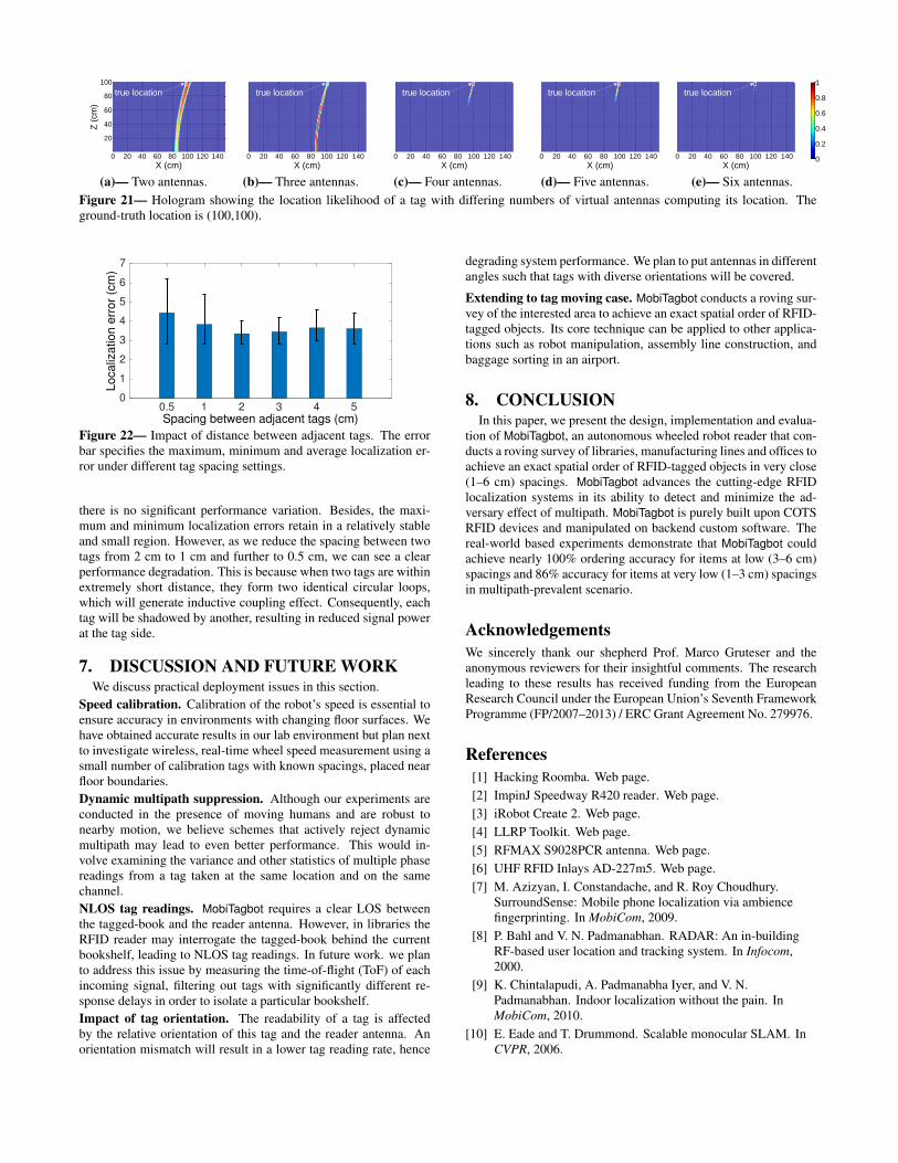
ber of virtual antennas (i.e., number of positions MobiTagbot readsfrom). In these experiments, we make the reader hop over 16 chan-nels and then capture the tag reading on each channel, respectively.Figure 21 shows the snapshot of the hologram generated by Mo-biTagbot under different number of virtual antenna settings. In thisfigure, we divide the X-Z plane into equal size blocks. The blocksize is set to 1 cm. The value on each block represents the likeli-hood of tag existing. The ground-truth of the tag is (100,100). Asthe result indicates, the localization accuracy improves significantlywith the increasing number of virtual antennas we use. Specifically,when the number of virtual antennas is large such as five or six, thehologram combination inherently reinforces the true location andremoves the false positives. In contrast, when the number of vir-tual antennas is small, e.g., 2 or 3, the reinforcement is not stronghence MobiTagbot fails to distinguish the true location from a set oflocation candidates.
6.4.4 Varying the spacing between adjacent tagsWe next examine how MobiTagbot performs with different adja-
cent tag spacings. In these experiments, we vary the tag spacingfrom 0.5 cm to 5 cm, and plot the localization accuracy in Fig-ure 22. As this figure shows, when the spacing is large, i.e., > 3 cm,
0 20 40 60 80 100 120 140
20
40
60
80
100
X (cm)
Z (
cm
)true location
0 20 40 60 80 100 120 140
X (cm)
true location
(a)— Two antennas.
0 20 40 60 80 100 120 140
X (cm)
true location
0 20 40 60 80 100 120 140
X (cm)
true location
(b)— Three antennas.
0 20 40 60 80 100 120 140
X (cm)
true location
0 20 40 60 80 100 120 140
X (cm)
true location
(c)— Four antennas.
0 20 40 60 80 100 120 140
X (cm)
true location
0 20 40 60 80 100 120 140
X (cm)
true location
(d)— Five antennas.
0 20 40 60 80 100 120 140
X (cm)
true location
0 20 40 60 80 100 120 140
X (cm)
true location
0
0.2
0.4
0.6
0.8
1
(e)— Six antennas.Figure 21— Hologram showing the location likelihood of a tag with differing numbers of virtual antennas computing its location. Theground-truth location is (100,100).
0.5 1 2 3 4 5Spacing between adjacent tags (cm)
0
1
2
3
4
5
6
7
Lo
ca
liza
tion
err
or
(cm
)
Figure 22— Impact of distance between adjacent tags. The errorbar specifies the maximum, minimum and average localization er-ror under different tag spacing settings.
there is no significant performance variation. Besides, the maxi-mum and minimum localization errors retain in a relatively stableand small region. However, as we reduce the spacing between twotags from 2 cm to 1 cm and further to 0.5 cm, we can see a clearperformance degradation. This is because when two tags are withinextremely short distance, they form two identical circular loops,which will generate inductive coupling effect. Consequently, eachtag will be shadowed by another, resulting in reduced signal powerat the tag side.
7. DISCUSSION AND FUTURE WORKWe discuss practical deployment issues in this section.
Speed calibration. Calibration of the robot’s speed is essential toensure accuracy in environments with changing floor surfaces. Wehave obtained accurate results in our lab environment but plan nextto investigate wireless, real-time wheel speed measurement using asmall number of calibration tags with known spacings, placed nearfloor boundaries.Dynamic multipath suppression. Although our experiments areconducted in the presence of moving humans and are robust tonearby motion, we believe schemes that actively reject dynamicmultipath may lead to even better performance. This would in-volve examining the variance and other statistics of multiple phasereadings from a tag taken at the same location and on the samechannel.NLOS tag readings. MobiTagbot requires a clear LOS betweenthe tagged-book and the reader antenna. However, in libraries theRFID reader may interrogate the tagged-book behind the currentbookshelf, leading to NLOS tag readings. In future work. we planto address this issue by measuring the time-of-flight (ToF) of eachincoming signal, filtering out tags with significantly different re-sponse delays in order to isolate a particular bookshelf.Impact of tag orientation. The readability of a tag is affectedby the relative orientation of this tag and the reader antenna. Anorientation mismatch will result in a lower tag reading rate, hence
degrading system performance. We plan to put antennas in differentangles such that tags with diverse orientations will be covered.
Extending to tag moving case. MobiTagbot conducts a roving sur-vey of the interested area to achieve an exact spatial order of RFID-tagged objects. Its core technique can be applied to other applica-tions such as robot manipulation, assembly line construction, andbaggage sorting in an airport.
8. CONCLUSIONIn this paper, we present the design, implementation and evalua-
tion of MobiTagbot, an autonomous wheeled robot reader that con-ducts a roving survey of libraries, manufacturing lines and offices toachieve an exact spatial order of RFID-tagged objects in very close(1–6 cm) spacings. MobiTagbot advances the cutting-edge RFIDlocalization systems in its ability to detect and minimize the ad-versary effect of multipath. MobiTagbot is purely built upon COTSRFID devices and manipulated on backend custom software. Thereal-world based experiments demonstrate that MobiTagbot couldachieve nearly 100% ordering accuracy for items at low (3–6 cm)spacings and 86% accuracy for items at very low (1–3 cm) spacingsin multipath-prevalent scenario.
AcknowledgementsWe sincerely thank our shepherd Prof. Marco Gruteser and theanonymous reviewers for their insightful comments. The researchleading to these results has received funding from the EuropeanResearch Council under the European Union’s Seventh FrameworkProgramme (FP/2007–2013) / ERC Grant Agreement No. 279976.
References[1] Hacking Roomba. Web page.[2] ImpinJ Speedway R420 reader. Web page.[3] iRobot Create 2. Web page.[4] LLRP Toolkit. Web page.[5] RFMAX S9028PCR antenna. Web page.[6] UHF RFID Inlays AD-227m5. Web page.[7] M. Azizyan, I. Constandache, and R. Roy Choudhury.
SurroundSense: Mobile phone localization via ambiencefingerprinting. In MobiCom, 2009.
[8] P. Bahl and V. N. Padmanabhan. RADAR: An in-buildingRF-based user location and tracking system. In Infocom,2000.
[9] K. Chintalapudi, A. Padmanabha Iyer, and V. N.Padmanabhan. Indoor localization without the pain. InMobiCom, 2010.
[10] E. Eade and T. Drummond. Scalable monocular SLAM. InCVPR, 2006.

[11] I. Ehrenberg, C. Floerkemeier, and S. Sarma. Inventorymanagement with an RFID-equipped mobile robot. In CASE,2007.
[12] H. Ermert and R. Karg. Multi-frequency acousticalholography. TOSU, 1979.
[13] B. Ferris, D. Fox, and N. D. Lawrence. WiFi-SLAM usingGaussian Process latent variable models. In IJCAI, 2007.
[14] A. Flint, C. Mei, I. Reid, and D. Murray. Growingsemantically meaningful models for visual SLAM. In CVPR,2010.
[15] K. R. Joshi, S. S. Hong, and S. Katti. PinPoint: Localizinginterfering radios. In NSDI, 2013.
[16] M. Kotaru, K. Joshi, D. Bharadia, and S. Katti. SpotFi:Decimeter level localization using WiFi. In SIGCOMM,2015.
[17] X. Li, Y. Zhang, and M. G. Amin. Multifrequency-basedrange estimation of RFID tags. In RFID, 2009.
[18] H. Lim, L.-C. Kung, J. C. Hou, and H. Luo.Zero-configuration, robust indoor localization: Theory andexperimentation. In Infocom, 2005.
[19] T. Liu, L. Yang, Q. Lin, Y. Guo, and Y. Liu. Anchor-freebackscatter positioning for RFID tags with high accuracy. Ininfocom, 2014.
[20] R. Miesen, F. Kirsch, and M. Vossiek. Holographiclocalization of passive UHF RFID transponders. In RFID,2011.
[21] A. Musa and J. Eriksson. Tracking unmodified smartphonesusing Wi-Fi monitors. In SenSys, 2012.
[22] L. M. Ni, Y. Liu, Y. C. Lau, and A. P. Patil. LANDMARC:indoor location sensing using active RFID. Wirelessnetworks, 2004.
[23] A. Parr, R. Miesen, and M. Vossiek. Inverse SAR approachfor localization of moving RFID tags. In RFID, 2013.
[24] A. Rai, K. K. Chintalapudi, V. N. Padmanabhan, and R. Sen.Zee: zero-effort crowdsourcing for indoor localization. InMobiCom, 2012.
[25] S. Sen, J. Lee, K.-H. Kim, and P. Congdon. Avoidingmultipath to revive inbuilding WiFi localization. In MobiSys,2013.
[26] S. Sen, B. Radunovic, R. R. Choudhury, and T. Minka. Youare facing the Mona Lisa: Spot localization using PHY layerinformation. In MobiSys, 2012.
[27] L. Shangguan, Z. Yang, A. X. Liu, Z. Zhou, and Y. Liu.Relative localization of RFID tags using spatial-temporalphase profiling. In NSDI, 2015.
[28] G. Shen, Z. Chen, P. Zhang, T. Moscibroda, and Y. Zhang.Walkie-Markie: Indoor pathway mapping made easy. InNSDI, 2013.
[29] H. Strasdat, A. J. Davison, J. Montiel, and K. Konolig.Double window optimisation for constant time visualSLAM. In ICCV, 2011.
[30] L. Sun, S. Sen, D. Koutsonikolas, and K.-H. Kim. WiDraw:Enabling hands-free drawing in the air on commodity WiFidevices. In MobiCom, 2015.
[31] M. Vossiek, V. Magori, and H. Ermert. An ultrasonicmulti-element sensor system for position invariant objectidentification. In US, 1994.
[32] M. Vossiek, A. Urban, S. Max, and P. Gulden. Inversesynthetic aperture secondary radar concept for precisewireless positioning. TMTT, 2007.
[33] H. Wang, S. Sen, A. Elgohary, M. Farid, M. Youssef, andR. R. Choudhury. No need to war-drive: unsupervised indoorlocalization. In MobiSys, 2012.
[34] J. Wang and D. Katabi. Dude, where’s my card?: RFIDpositioning that works with multipath and non-line of sight.In SIGCOMM, 2013.
[35] J. Wang, D. Vasisht, and D. Katabi. RF-IDraw: Virtual touchscreen in the air using RF signals. In SIGCOMM, 2014.
[36] Y. Wang, J. Liu, Y. Chen, M. Gruteser, J. Yang, and H. Liu.E-eyes: device-free location-oriented activity identificationusing fine-grained WiFi signatures. In MobiCom, 2014.
[37] K. Whitehouse, C. Karlof, and D. Culler. A practicalevaluation of radio signal strength for ranging-basedlocalization. MCCR, 2007.
[38] C. Wong, R. Klukas, and G. Messier. Using WLANinfrastructure for Angle-of-Arrival indoor user location. InVTC, 2008.
[39] J. Xiong and K. Jamieson. ArrayTrack: A fine-grainedindoor location system. In NSDI, 2013.
[40] J. Xiong, K. Sundaresan, and K. Jamieson. ToneTrack:Leveraging frequency-agile radios for time-based indoorwireless localization. In MobiCom, 2015.
[41] L. Yang, Y. Chen, X.-Y. Li, C. Xiao, M. Li, and Y. Liu.Tagoram: Real-time tracking of mobile RFID tags to highprecision using COTS devices. In MobiCom, 2014.
[42] Z. Yang, C. Wu, and Y. Liu. Locating in fingerprint space:wireless indoor localization with little human intervention.In MobiCom, 2012.
[43] M. Younis, C. Fischer, and W. Wiesbeck. Digitalbeamforming in SAR systems. TOGRS, 2003.
[44] M. Youssef and A. Agrawala. The Horus WLAN locationdetermination system. In MobiSys, 2005.
[45] C. Zhou and J. D. Griffin. Accurate phase-based rangingmeasurements for backscatter RFID tags. Antennas andWireless Propagation Letters, 2012.


![Inferring Motion Direction using Commodity Wi-Fi …tns.thss.tsinghua.edu.cn/~cswu/papers/chi17_widance...Sports and Wii Fit) and academia [7, 24]. Most interfaces for Permission to](https://static.fdocuments.in/doc/165x107/5f55e0031bc4aa682101c4dd/inferring-motion-direction-using-commodity-wi-fi-tnsthss-cswupaperschi17widance.jpg)