
The Cricket Compass for Context-Aware Mobile Applications Cric… · The Cricket Compass for...
14
The Cricket Compass for Context-Aware Mobile Applications Nissanka B. Priyantha, Allen K. L. Miu, Hari Balakrishnan, and Seth Teller MIT Laboratory for Computer Science Abstract 1. Introduction Permission to make digital or hard copies of part or all of this work or personal or classroom use is granted without fee provided that copies are not made or distributed for profit or commercial advantage and that copies bear this notice and the full citation on the first page. To copy otherwise, to republish, to post on servers, or to redistribute to lists, requires prior specific permission and/or a fee. ACM SIGMOBILE 7/01 Rome, Italy ' 2001 ACM ISBN 1-58113-422-3/01/07$5.OO 1
Transcript of The Cricket Compass for Context-Aware Mobile Applications Cric… · The Cricket Compass for...

The Cricket Compass for Context-Aware MobileApplications
Nissanka B. Priyantha, Allen K. L. Miu, Hari Balakrishnan, and Seth TellerMIT Laboratory for Computer Science
{bodhi,aklmiu,hari,seth}@lcs.mit.eduhttp://nms.lcs.mit.edu/cricket/
AbstractThe abilit y to determine the orien tation of a device isof fundamental importancein con text-aw areand location-dependent mobile computing. By analogy to a traditionalcompass, knowledge of orientation through the Cricket c om-pass attached to a mobile device enhances various applica-tions, including eÆcient way-�nding and navigation, direc-tional service disco very,and \augmented-realit y" displays.Our compass infrastructure enhances the spatial inferencecapabilit yof the Cric ketindoor location system [20], andenables new pervasiv e computing applications.
Using �xed active beacons and carefully placed passive ul-trasonic sensors, w e sho whow to estimate the orien tationof a mobile device to within a few degrees, using precise,sub-cen timeter di�erences in distance estimates from a bea-con to each sensor on the compass. Then, given a set of�xed, active position beacons whose locations are known, wedescribe an algorithm that combines sev eral carrier arriv altimes to produce a robust estimate of the rigid orientationof the mobile compass.
The hardware of the Cricket compass is small enough to beintegrated with a handheld mobile device. It includes �vepassiv e ultrasonic receivers, each 0.8cm in diameter, arrayedin a \V" shape a few centimeters across. Cric ket beaconsdeplo yed throughout a building broadcast coupled 418MHzRF packet data and a 40KHz ultrasound carrier, which areprocessed by the compass softw are to obtain di�erential dis-tance and position estimates. Our experimental results sho wthat our prototype implementation can determine compassorien tation to within 3 degrees when the true angle lies be-tween �30 degrees, and to within 5 degrees when the trueangle lies between �40 degrees, with respect to a �xed bea-con.
1. IntroductionContext-aware applic ations, whic h adapttheir behavior to
environmental con text such as physical location, are an im-portan t class of applications in emerging pervasive comput-ing en vironments [17]. Examples include location-aware ap-plications that enable users to discover resources in theirph ysical pro ximity [14, 20], active maps that automaticallychange as a user moves [22], and applications whose user in-terfaces adapt to the user's location. A signi�cant amount ofprevious work has focused on providing device position ca-pabilit y indoors, including the Active Badge [26], Bat [14],RADAR [5], and Cricket [20] systems.
An important aspect of con text, which is related to phys-ical position, is the orientation of a device (or user) withrespect to one or more landmarks in a region. A pervasiv ecomputing application can bene�t from knowing this infor-mation, for instance by pro viding the ability to adapt a userinterface to the direction in which a user is standing or point-ing. Our �rst motivating application is called theWay�nder.We envision this application to run on a handheld computerand help sighted or blind people navigate to w ard a destina-tion in an unfamiliar setting. For example, the Way�ndermight lead a visitor from the entry lobby of a building tothe oÆce of the person hosting the visitor, or to a semi-nar room. The Way�nder gives incremental directions tothe user on dynamically retrieved (\activ e") maps [22, 20],using the user's position and orientation with respect to a�xed set of wireless beacons placed throughout the building.The second motivating application is called the View�nder.The user can point it in any direction, and specify a \sweepangle" and maximum distance. Using an active map inte-grated with a resource discovery system (e.g., the IntentionalNaming System, INS [1]), the View�nder then retrieves anddispla ys a representation of the set of devices and serviceslying inside the sector of interest speci�ed by the user andallows the user to interact with these services via the repre-sentation on the map. A third motivating application is inthe design of \augmented-realit y" displays, where the user'sview of the environment is overlaid with information aboutother objects present within that environment, and adaptsto the direction that the user is looking toward [4, 25].
The underlying capability required for these applications isakin to a \softw arecompass," whic h,endowed with a se-mantic map of its con text and accurate knowledge of itsown position and orientation, can inform the user of inter-esting resources and how to get to those resources. This pa-per describes the design and implementation of the Cricketcompass system, consisting of a set of active beacons, passive
Permission to make digital or hard copies of part or all of this work or personal or classroom use is granted without fee provided that copies are not made or distributed for profit or commercial advantage and that copies bear this notice and the full citation on the first page. To copy otherwise, to republish, to post on servers, or to redistribute to lists, requires prior specific permission and/or a fee. ACM SIGMOBILE 7/01 Rome, Italy © 2001 ACM ISBN 1-58113-422-3/01/07�$5.OO
1
Some text in this electronic article is rendered in Type 3 or bitmapped fonts, and may display poorly on screen in Adobe Acrobat v. 4.0 and later. However, printouts of this file are unaffected by this problem. We recommend that you print the file for best legibility.

hardware sensors, and associated software algorithms. Thissystem enables a robust software compass capability for ahandheld device moving about inside a building.
The operating environment in the Cricket architecture is in-strumented with active beacons, each of which broadcastsits own known position over an RF channel together withan ultrasonic pulse [20]. One RF receiver and several pas-sive ultrasonic position receivers are precisely placed on acompass board. Software running on-board uses the dif-ferentials in distances reported by the ultrasonic receiversto infer the orientation (or \heading") of the device. TheCricket compass reports position and orientation indoors fora handheld, mobile device, and informs an application run-ning on the device of the position and orientation in a localcoordinate system established by the �xed set of beacons.
The �rst challenge in deriving orientation for a small devicearises from the need for very accurate di�erential distanceestimates: estimating orientation to within a few degreesof the correct value requires di�erential distance estimatesto be of sub-centimeter accuracy, which is at least an orderof magnitude smaller than the currently best available lin-ear distance estimation technologies. We show how to dothis using multiple carefully placed receivers. The secondchallenge arises due to variation in the speed of sound dueto temperature and humidity, which a�ects the accuracyof position estimates. Rather than explicitly measuring thisparameter with climate sensors, we calculate it directly fromobserved propagation times.
The Cricket compass system proposed in this paper ad-dresses several problems with existing methods for orien-tation estimation. A traditional magnetic compass can es-timate orientation, but exhibits enormous errors when nearmagnetic or time-varying electric �elds, both of which arerather common in most modern buildings with computersand other equipment. Orientation can be inferred from amoving position sensor, but this usually requires large orfast user motions, which is undesirable in several applica-tions. Active sensors on user devices typically lead to sys-tems that track users [14, 26], which su�er from potentialcompromises to user privacy [19, 20]. In contrast, Cricketrequires a small number of beacons at known positions ineach room to instrument a building, but enables locationand orientation for a passive handheld device without re-quiring any user motion. We have built several prototypebeacons and a receiver compass con�guration, and reportexperimental data that show that our software compass cor-rectly estimates orientation to within a few degrees. We alsodescribe a View�nder application developed using this ca-pability. The Cricket system is being used in MIT's ProjectOxygen in a variety of pervasive computing scenarios [17].
The rest of this paper is organized as follows. Section 2 de-tails the design of the Cricket compass, describing its theoryof operation, di�erential distance estimation, and coordinatedetermination algorithms. Section 3 discusses our imple-mentation and Section 4 presents experimental results andan error analysis. Section 5 discusses some improvementsbased on our experimental results. Section 6 describes theView�nder application. We compare our system to previouswork in Section 7 and conclude in Section 8.
Heading relative to Bon horizontal planeUser device
parallel to groundon horizontal plane
Beacons onceiling
θ
B
Compass hardware
Figure 1: Setup of beacons on the ceiling of a roomand a user device with attached compass hardware.The Cricket compass solves the problem of obtain-ing the precise position and orientation of the userdevice relative to a coordinate system de�ned by thebeacons.
2. Design of the Cricket CompassFigure 1 shows a user device with attached compass hard-ware in a room with beacons placed on the ceiling. Whenthe device is held parallel to the horizontal plane, � is theangle formed by the heading direction shown, with the pointwhere the perpendicular from beacon B intersects the hori-zontal plane. We are interested in precisely estimating �.
The basic idea is to use one RF receiver to receive coordi-nate information from the beacons, and multiple, carefullyplaced, ultrasonic receivers on the compass attached to thedevice to obtain the di�erential distance estimates of a bea-con to each ultrasonic receiver. � is a function of the di�er-ential distance of the linear distance of the compass from thebeacon, and of the height of the beacon (ceiling) above theplane of the compass. We obtain per-beacon linear distanceestimates by di�erencing the arrival times of coupled RFand ultrasonic signals sent from each beacon [20]. To obtainthe height of the beacon from the compass, we estimate theposition coordinates of the compass from the position coor-dinates disseminated by multiple nearby beacons.
The rest of this section describes how this idea can be re-alized in practice. We start by describing how directionalinformation can be obtained using di�erences in distancebetween a beacon and di�erent receivers. We describe atechnique to achieve the required precision of di�erentialdistance estimates, using di�erential phase information ofthe ultrasonic waves reaching the receivers. Finally, weshow how to obtain accurate position coordinate informa-tion without explicit knowledge of the speed of sound, com-pensating for its variation with physical conditions.
2.1 Theory of OperationFigure 2 shows a beacon B, and a compass with two ultra-sonic receivers, R1 and R2, which are located at a distance Lapart from each other. The angle of rotation of the compass,
2

d1 d2 z
LθHeading
Beacon B (on ceiling)
Horizontal planex
R1
R2
Figure 2: Determining the angle of orientation alongthe horizontal plane, �, using distance estimates.Observe that the heading is perpendicular to theline joining the ultrasonic compass receivers, R1 andR2, which are placed at a distance L from each other.
�, with respect to the beacon B, is related to the di�erencein distances d1 and d2, where d1 and d2 are the distancesof receivers R1 and R2 from B. The vertical and horizontaldistances from the center of the compass to B are denotedby z and x, respectively.
Figure 3 shows the beacon B from Figure 2 projected on tothe horizontal plane along which the compass is aligned. Inthis �gure, x1 and x2 are the projections of distances d1 andd2 on to the horizontal plane. We assume that the compassis held parallel to the horizontal plane.
From Figure 2:
x21 = d21 � z2 (1)
x22 = d22 � z2 (2)
x =p
�d2 � z2
where �d � d1+d22
when d1; d2 � L.
From Figure 3:
x21 = (L
2cos �)2 + (x�
L
2sin �)2
and
x22 = (L
2cos �)2 + (x+
L
2sin �)2
) x22 � x21 = 2Lx sin �
Substituting for x21 and x22 from Equations (1) and (2), weget:
sin � =d2 + d12Lx
� (d2 � d1) (3)
This may be rewritten as:
sin � =d2 � d1
Lq1� ( z�d )
2
(4)
Equation (4) implies that it suÆces to estimate two quan-tities in order to determine the orientation of the compass
θ
θ
x1 x x2
L/2
L/2
Figure 3: A rotated compass leads to a di�erencein distances between the beacon and each of the re-ceivers. This �gure is the result of projecting thebeacon onto the horizontal plane of the compass.
with respect to a beacon: (i) (d2�d1), the di�erence in dis-tances of the two receivers from the beacon, and (ii) z= �d, theratio of the height of the beacon from the horizontal planeon which the compass is placed to the distance of the bea-con from the center of the compass. In practice, however,no measurements are perfect. Our goal is to estimate eachof these quantities with high precision, so as to produce asuÆciently accurate estimate of �.
One way of precisely estimating (d2 � d1) would be toprecisely measure d1 and d2 separately, but that is easiersaid than done. Consider, for example, a situation whereL = 5cm, and � = 10Æ, with a beacon at a distance of 2 me-ters and a height of 1 meter from the receivers. From Equa-tion (4), the value of (d2 � d1) in this case is only � 0:6cm,which is about an order of magnitude smaller than what cur-rent technologies can achieve in terms of linear distance es-timates [14, 20]1. Since our goal is to devise a compass withphysically small dimensions, comparable in size to handheldPDAs, and still achieve high directional accuracy, we needan alternative method to estimate this di�erential distance.
Our solution to this problem tracks the phase di�erence be-tween the ultrasonic signals at two di�erent receivers andprocesses this information. We �nd that this approach al-lows us to obtain di�erential distance estimates with sub-centimeter accuracy. This is described in Section 2.2.
The second quantity, z= �d, is estimated by determining the(x; y; z) coordinates of the compass with respect to the planeformed by the beacons (the xy plane). We do this by placingmultiple beacons in a room and estimating the time it takesfor the ultrasonic signal to propagate between them and thecompass. However, because the speed of sound varies withambient temperature and humidity, we must estimate thisquantity as well. This is described in Section 2.3.
1The worst-case error in (d2�d1) is equal to the sum of theerrors in d1 and d2.
3

From beacon
L
d1−d2
d1 d2
Figure 4: Receivers R1 and R2 can measure the dif-ferential distance from a far-away beacon.
2.2 Estimating Differential DistanceConsider two ultrasonic receivers R1 and R2 located a dis-tance L apart, as shown in Figure 4. Let d1 and d2 bethe distances to receivers R1 and R2 from beacon B. LetÆd = d1 � d2 and let W1 and W2 be the ultrasonic wave-forms received by R1 and R2 from B. The phase di�erencebetween the waveforms at the two receivers, �, depends onthe di�erence in distances traversed from B to the receiversby the ultrasonic signal and the wavelength � of the signal,and may be expressed as:
� =(Æd)
�� 2� (5)
We call this the actual phase di�erence between the twosignals and denote it by �.
Because it is diÆcult to correctly determine the start of pe-riodic waveforms, we can only obtain estimates for a wave-form's phase in the range (��; �) from repeated low-to-hightransitions of the signal. Unfortunately, a given observedphase di�erence between two waveforms, �, can correspondto an in�nite number of actual phase di�erences, all sepa-rated by 2�. This in turn leads to multiple possibilities forÆd.
One way to solve this problem is to observe from Equation(5) that as long as Æd < �=2, � = �, and there is no am-biguity. Since d1; d2; and L are three sides of a triangle,L � jd1 � d2j = jÆdj, and we can therefore place the re-ceivers at a distance L < �=2 to unambiguously determine� and therefore uniquely estimate (d1 � d2).
For a 40 KHz ultrasonic waveform at a temperature of 25ÆCand 50% humidity, �=2 = 4:35 mm. This is smaller thanthe size of most available ultrasonic signal receivers, whichare typically on the order of about 1 cm. Lowering thecarrier frequency is not an option, since this would make itaudible to humans. We therefore need a nice general methodto place receivers to unambiguously determine the phasedi�erence.
One way of tackling this is to carefully place three receiversalong a line, as shown in Figure 5, and use a pair of observed
From far-away beacon
L12 L23R1 R2 R3
d 1-d 2
d 2-d 3
Figure 5: Using three receivers to measure (d1�d2).
phase di�erences to estimate an actual di�erence. The in-tuition is that if the two inter-receiver distances, L12 andL23 are chosen carefully, then the actual phase di�erencebetween receivers 1 and 2 (say) can be disambiguated byusing the phase di�erence between receivers 2 and 3, sincethe two phase di�erences are not independent.
Let �12 and �23 be the actual phase di�erences of a beacon'swaveform between receivers 1 and 2 and receivers 2 and 3,respectively. Then,
�ij = 2nij� + �ij
for each pair of receivers (i; j), where nij are integers and�� < �ij � �. Because the actual phase di�erence betweentwo receivers is proportional to the distance traversed by thesignal from the beacon to each of the receivers, �23=�12 =(d2�d3)=(d1�d2) � L23=L12 when di � Lij . This is shownin Figure 5.
What we will show is that it is possible to pick L12 and L23such that one can use two sets of observed phase di�erences�12; �23 to unambiguously estimate the actual phase di�er-ence �12. In particular, we show the following result:If L12 and L23 are relatively prime multiples of �=2, then it
is possible to use �12 and �23 to unambiguously obtain theactual phase di�erences �12 and �23.
We argue this by contradiction. Suppose in fact there aretwo possible actual phase di�erences corresponding to agiven observed phase di�erence for each receiver. For pair(i; j), call these di�erences �0
ij and �00
ij . Then, the followingsets of equations hold:
�0
ij = 2n0
ij� + �ij
�00
ij = 2n00
ij� + �ij
Since each observed �12 is related to the corresponding �23by the ratio L23=L12, the above equations can be rewrittenas:
2n0
23� + �23 = (L23=L12)(2n0
12 + �12) (6)
2n00
23� + �23 = (L23=L12)(2n00
12 + �12) (7)
4

R1
R2
B1
B2
θ
θ X
X
Y
Y
Figure 6: � is ambiguous|the beacon can be at ei-ther B1 or B2.
Subtracting Equation (7) from Equation (6) and rearrang-ing, we get:
L12(n0
23 � n00
23) = L23(n0
12 � n00
12) (8)
Let us express Lij as lij�=2, which expresses the separationbetween receivers as an integral multiple of �=2. Equation(8) is then equivalent to:
l12(n0
23 � n00
23) = l23(n0
12 � n00
12) (9)
where each of the lij and nij are integers.
Notice that jnij j� � Æd, the separation in distance betweenthe carrier waveforms at receiver i and receiver j, and Æd �Lij = lij�=2, for each pair (i; j) = (1; 2); (2; 3). This meansthat j(n0
ij � n00
ij)�j < 2Lij = lij�. (In fact, j(n0
ij � n00
ij)�jmay be equal to 2Lij , but only if the beacon lies on the samehorizontal plane as the compass. This situation is unlikely inpractice, and detectable if it does occur.) Therefore, jn0
ij �n00
ij j < lij . Thus, if Equation (9) is to be satis�ed, l12 andl23 cannot be relatively prime.
Hence, it is possible to unambiguously derive an actual phasedi�erence (�ij) in the range of [0; Lij ] from an observed one(�ij) by picking L12 and L23 to be relatively prime integralmultiples of �=2. For example, we can pick L12 = 2� andL23 = 1:5�. Thus, knowing �, we get the exact Æd neededfor estimating � in Equation (4).
2.2.1 Disambiguating �
Using Equation (4) and the techniques discussed thus far,we can determine sin � between the compass and a particularbeacon B. But as Figure 6 shows, in general, there are twolocations B1, B2 for a beacon B that result in the same � atthe compass. This is due to symmetry of the system aboutthe line X{X. An analytical way of understanding this isto observe that there are two values of � in the range [0; 2�)for a given value of sin �. This ambiguity in the location ofthe beacon prevents us from determining a unique value forthe heading.
We solve this by using two sets of non-collinear receiver-triplets to break the symmetry. We place the two sets of
θ
θ X
X
Y
Y
ββ
B
Figure 7: Two sets of receivers can break the sym-metry. One set of receiver triplets lies on the X-Xline and the second set lies on the Y -Y line.
1
2
3
4
5
Figure 8: Five receivers on a compass forming twoperpendicular receiver-triplets, which are used tounambiguously infer the heading with respect to abeacon.
5
Beacons onceiling
B
y
x z
(xi, yi, 0)
(x, y, z)Compasscoordinates
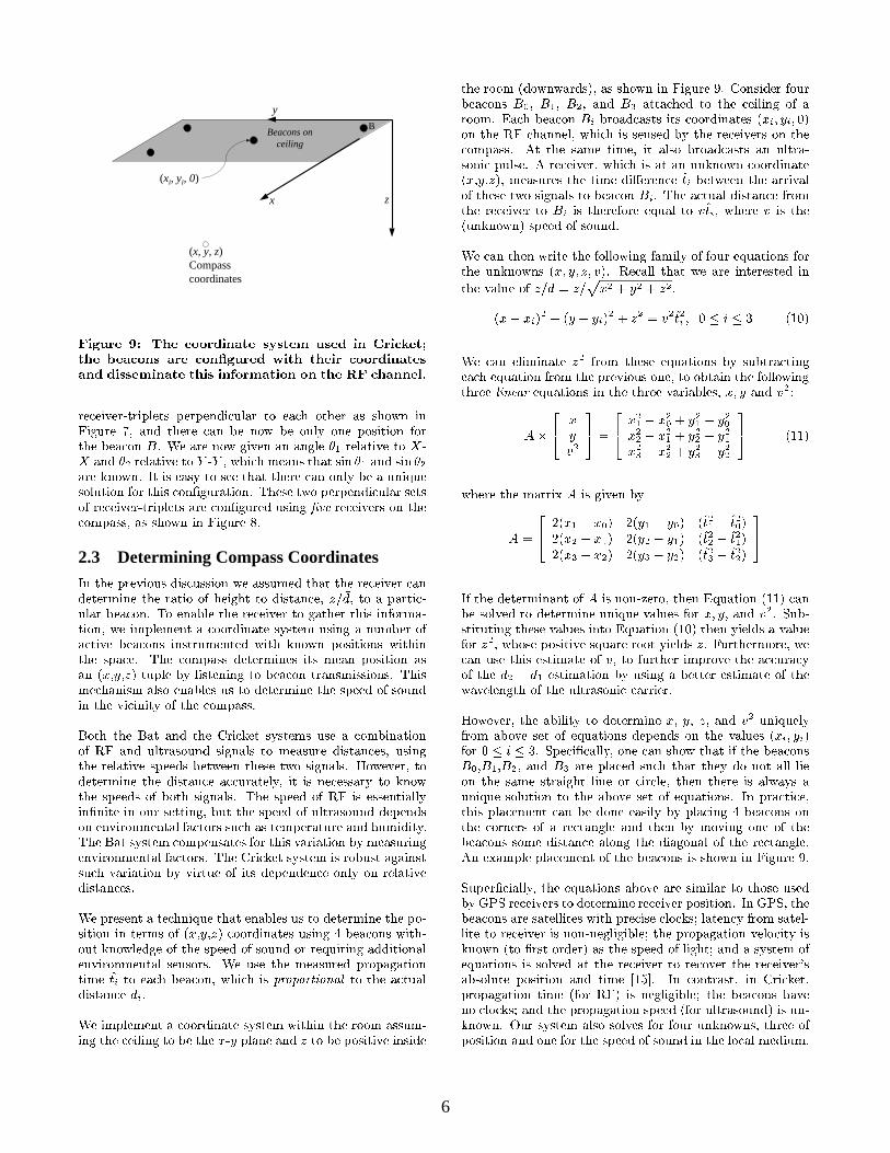
Figure 9: The coordinate system used in Cricket;the beacons are con�gured with their coordinatesand disseminate this information on the RF channel.
receiver-triplets perpendicular to each other as shown inFigure 7, and there can be now be only one position forthe beacon B. We are now given an angle �1 relative to X-X and �2 relative to Y -Y , which means that sin �1 and sin �2are known. It is easy to see that there can only be a uniquesolution for this con�guration. These two perpendicular setsof receiver-triplets are con�gured using �ve receivers on thecompass, as shown in Figure 8.
2.3 Determining Compass CoordinatesIn the previous discussion we assumed that the receiver candetermine the ratio of height to distance, z= �d, to a partic-ular beacon. To enable the receiver to gather this informa-tion, we implement a coordinate system using a number ofactive beacons instrumented with known positions withinthe space. The compass determines its mean position asan (x,y,z) tuple by listening to beacon transmissions. Thismechanism also enables us to determine the speed of soundin the vicinity of the compass.
Both the Bat and the Cricket systems use a combinationof RF and ultrasound signals to measure distances, usingthe relative speeds between these two signals. However, todetermine the distance accurately, it is necessary to knowthe speeds of both signals. The speed of RF is essentiallyin�nite in our setting, but the speed of ultrasound dependson environmental factors such as temperature and humidity.The Bat system compensates for this variation by measuringenvironmental factors. The Cricket system is robust againstsuch variation by virtue of its dependence only on relativedistances.
We present a technique that enables us to determine the po-sition in terms of (x,y,z) coordinates using 4 beacons with-out knowledge of the speed of sound or requiring additionalenvironmental sensors. We use the measured propagationtime t̂i to each beacon, which is proportional to the actualdistance di.
We implement a coordinate system within the room assum-ing the ceiling to be the x-y plane and z to be positive inside
the room (downwards), as shown in Figure 9. Consider fourbeacons B0, B1, B2, and B3 attached to the ceiling of aroom. Each beacon Bi broadcasts its coordinates (xi; yi; 0)on the RF channel, which is sensed by the receivers on thecompass. At the same time, it also broadcasts an ultra-sonic pulse. A receiver, which is at an unknown coordinate(x,y,z), measures the time di�erence t̂i between the arrivalof these two signals to beacon Bi. The actual distance fromthe receiver to Bi is therefore equal to vt̂i, where v is the(unknown) speed of sound.
We can then write the following family of four equations forthe unknowns (x; y; z; v). Recall that we are interested in
the value of z= �d = z=px2 + y2 + z2.
(x� xi)2 + (y � yi)
2 + z2 = v2 t̂2i ; 0 � i � 3 (10)
We can eliminate z2 from these equations by subtractingeach equation from the previous one, to obtain the followingthree linear equations in the three variables, x; y and v2:
A�
24 x
yv2
35 =
24 x21 � x20 + y21 � y20
x22 � x21 + y22 � y21x23 � x22 + y23 � y22
35 (11)
where the matrix A is given by
A =
24 2(x1 � x0) 2(y1 � y0) (t̂21 � t̂20)
2(x2 � x1) 2(y2 � y1) (t̂22 � t̂21)2(x3 � x2) 2(y3 � y2) (t̂23 � t̂22)
35
If the determinant of A is non-zero, then Equation (11) canbe solved to determine unique values for x; y; and v2. Sub-stituting these values into Equation (10) then yields a valuefor z2, whose positive square root yields z. Furthermore, wecan use this estimate of v, to further improve the accuracyof the d2 � d1 estimation by using a better estimate of thewavelength of the ultrasonic carrier.
However, the ability to determine x, y, z, and v2 uniquelyfrom above set of equations depends on the values (xi; yi)for 0 � i � 3. Speci�cally, one can show that if the beaconsB0,B1,B2, and B3 are placed such that they do not all lieon the same straight line or circle, then there is always aunique solution to the above set of equations. In practice,this placement can be done easily by placing 4 beacons onthe corners of a rectangle and then by moving one of thebeacons some distance along the diagonal of the rectangle.An example placement of the beacons is shown in Figure 9.
Super�cially, the equations above are similar to those usedby GPS receivers to determine receiver position. In GPS, thebeacons are satellites with precise clocks; latency from satel-lite to receiver is non-negligible; the propagation velocity isknown (to �rst order) as the speed of light; and a system ofequations is solved at the receiver to recover the receiver'sabsolute position and time [15]. In contrast, in Cricket,propagation time (for RF) is negligible; the beacons haveno clocks; and the propagation speed (for ultrasound) is un-known. Our system also solves for four unknowns, three ofposition and one for the speed of sound in the local medium.
6

3. ImplementationWe have implemented prototypes of the beacon and compasshardware described in Section 2. Each beacon is con�guredwith its position in a coordinate system, which it broadcastson a 418 MHz RF channel. Concurrent with each periodicRF broadcast, it sends a 500 �s ultrasonic pulse at 40 KHz,which are received at the compass ultrasonic receivers. Eachbeacon and compass has an on-board PIC microcontrollerthat implements the communication protocol and processesinformation. The rest of this section describes the details ofthe communication protocol between the beacons and com-pass, and how the compass processes the observed di�er-ential distance estimates to deduce the actual di�erentialdistances.
3.1 Protocol DetailsThe beacons in Cricket operate in an autonomous manner,without any centralized control of when they transmit in-formation [20]. To reduce inter-beacon interference at thereceivers, each beacon senses the RF carrier before trans-mitting a locally unique ID and its known position coordi-nates. In addition, each subsequent transmission is sent ata uniformly chosen random time after the previous one. Inour implementation, the average amount of time betweensuccessive transmissions is 250 ms. The packet format ofthe beacon includes information about the geographic space(e.g., an intentional name for resource discovery in INS [1],a URL as in CoolTown [8], etc.). Each packet is protectedusing a block-parity code. The compass detects collisionon the RF channel and discards samples that do not passa block-parity check, which helps it disambiguate betweenpotentially interleaved RF/ultrasound combinations sent ofseparate beacons.
The processing of ultrasonic signals is more involved. Thecompass hardware does analog-to-digital oversampling todetect low-to-high transitions from each ultrasonic receiver.In addition to processing RF information, the on-board PICmicrocontroller handles the ultrasonic signals received bythe several ultrasonic receivers on the compass to obtainphase di�erence estimates, and passes these to the softwarerunning on the attached device.
This software processes the raw data to obtain observeddi�erential distance estimates, and then convert them toactual di�erential distance estimates. It also infers thecoordinates of the compass relative to the coordinate systemde�ned by the beacons, and computes the orientation unitvector in that system. It calculates the angle relative toeach beacon and uses the smallest angle to derive theorientation vector. The reason for this will be clear fromSection 4, which shows that the accuracy of our systemworsens at large angles (greater than about 45 degrees).This also means that the system works best when it �ndsat least one beacon at an angle smaller than 45 degrees|since there are at least four beacons per space on eachceiling of interest, it is relatively straightforward to place,and �nd, at least one beacon in standard rectangular rooms.
0
0.2
0.4
0.6
0.8
1
-2 -1.5 -1 -0.5 0 0.5 1 1.5 2
Obs
erve
d D
iffer
entia
l Dis
tanc
e (U
nit:
1 w
avel
engt
h)
Actual Differential Distance Between Receivers 1-2 (Unit: 1 wavelength)
Mapping From Observed Differential Distance to Actual Differential Distance
Observable Distance 1-2Observable Distance 2-3
Observed Distance 1-2
Observed Distance 2-3Actual Distance 1-2
Figure 10: Finding the actual di�erential distancebetween R1 and R2 by using the observed di�erentialdistances from (R1; R2) and (R2; R3).
3.2 Differential Distance Estimation Algo-rithm
In our prototype, the ultrasonic receivers are set up accord-ing to Figure 8, where L12 = L14 = 2�, and L23 = L45 =1:5�. An interesting aspect of our implementation is themethod used to determine the unique actual di�erential dis-tance from the observed di�erential distance. The methoduses the intuition developed in Section 2.2, where an \ex-istence" argument was made for how to con�gure receiversto unambiguously resolve the actual phase di�erence. Al-though the argument was made in the \phase domain," theresults hold equivalently in the \wavelength domain," wherethe measured values are the di�erential distances in terms of�. However, the argument in Section 2.2 is not prescriptive,so we outline our implemented algorithm below.
Consider Figure 10, which plots the variation of observeddi�erential di�erence Æd0 as a function of the actual di�er-ential di�erence Æd for two pairs of receivers. One of thecurves (the solid line segments) shows the Æd012 variation forthe receiver pair (R1; R2), which are separated by a distanceL12 = 2�. The other curve (the dashed line segments) showsthe variation Æd023 for the receiver pair (R2; R3) separated byL23 = 1:5�. We normalized the curves to show the observedvariations of Æd012 and Æd023 as a function of Æd12; i.e., Æd
0
12
varies in the range [0; �] as Æd12 varies in [�2�; 2�].
Each curve is periodic with discontinuities. The observedvalue Æd0 varies in the range [0; �] because that is the rangeof measurable distance between two (time-shifted) wave-forms whose starting times are not known. The disconti-nuities are due to the fact that the observable di�erentialdistances follow the periodicity of the observed phase dif-ferences. The actual di�erential distances vary in the range[�L12; L12] for Æd12, and in the range [�L23; L23] for Æd23.But because we have normalized the curves as a function ofÆd12, the observed phase di�erential curve for the receiverpair (R2; R3) shown in Figure 10 also varies in the range[�L23 � L12=L23; L23 � L12=L23] = [�L12; L12] in the plot.The slope of each line segment is proportional to the nor-malized separation distance for that pair of receivers. Hence,the normalized curve for (R1; R2) has a slope of 1, while the
7

curve for (R2; R3) has a slope of L23=L12 = 3=4.
Note that because L12 and L23 are relatively prime mul-tiples of �=2, the periods (and discontinuities) for the twocurves always di�er, and the cycle of each curve (i.e., thediscontinuities) do not overlap each other more than once.Consequently, the two curves do not have a repeating pat-tern within the interested range [�L12; L12]. Hence, we geta unique solution for the actual Æd value for any given pairof observed Æd012 and Æd023 values.
Recall that the range of observable di�erential distances is[0; �]. From Figure 10, we see that any observed value withinthis range can be mapped to four possible solutions for the
actual Æd12. Let AÆd0
12 be the set of possible solutions de-rived from the observed value Æd012. Graphically, these arethe values on the horizontal axis extrapolated from the fourintersections between the y = Æd012 line and the observabledi�erential distance curve for the receiver (R1; R2). Then,given an observed Æd012, our task is to identify the actual
di�erential distance from the set AÆd0
12 .
By following the arguments presented in Section 2.2, we canuse the observed Æd023 to help us identify the correct solu-tion. From Figure 10, the observed Æd023 can be mappedto three possible solutions for the actual Æd12. Again, let
AÆd0
23 be the set of possible solutions using the observedvalue Æd023. Since we are guarenteed a unique solution forany given pair of observed values Æd012 and Æd023, we will
�nd exactly one matching solution that exists in both AÆd0
12
and AÆd0
23 . Thus, the �nal answer for the actual di�erential
distance Æd12 is a if and only if a 2 AÆd0
12 and a 2 AÆd0
23 .
For example, Figure 10 shows that for the ob-served Æd012 = 0:547 and Æd023 = 0:41025,
AÆd0
12 = f�1:453;�0:453; 0:547; 1:547g and AÆd0
23 =f�0:786; 0:547; 1:880g. Hence, the �nal solution is
Æd12 = 0:547 because this value exists in both AÆd0
12 andAÆd0
23 .
One caveat about this algorithm for �nding the actual phasedi�erential distance is that measurement errors may produce
no matching solution that exists in both AÆd0
12 and an AÆd0
23 .In such a situation, we �nd the closest matching solution by
choosing an a12 2 AÆd0
12 and a23 2 AÆd0
23 such that ja12�a23jis minimum. Then, we report the actual di�erential distanceto be a12+a23
2.
4. ExperimentsIn this section, we report on several performance experi-ments conducted with our Cricket compass implementation.In Section 5, we outline a few improvements that we intendto implement in the future, based on what we have learnedfrom these experiments.
We describe two distinct sets of experiments. First, we eval-uate the eÆcacy of our di�erential distance estimation tech-nique as a function of the angle � between the compass andone �xed beacon using the techniques of Section 2.2. Then,we attach multiple beacons at di�erent places on a ceilingand measure the accuracy of coordinate estimation using the
-80
-60
-40
-20
0
20
40
60
80
-80 -60 -40 -20 0 20 40 60 80
Ave
rage
Ang
le E
stim
ate
Usi
ng M
easu
red
D2-
D1
Val
ues
True Angle
Average Angle Estimate
Figure 11: Average angle estimates versus true an-gle values. The error bars indicate the absolute an-gle errors for all three trials. The line y = x plots theideal relationship between the true and estimatedangle values.
techniques of Section 2.3. Finally, we combine the results ofthese experiments to perform an analytic error analysis ofEquation (4) to derive an upper bound on the end-to-enderrors one might expect in practice. We do this becauseour current prototype hardware does not allow us to ob-tain the average and di�erential beacon distances simulta-neously; while we are building this combined hardware, wedo want to get a sense of how accurate our system is likely tobe. The following sections demonstrate that our di�erentialdistance and position estimation methods work well.
4.1 Differential Distance EstimationIn this set of experiments, we use the setup shown in Figure 2to measure the accuracy of the di�erential distance values,d2 � d1, at di�erent values of �. We place the beacon suchthat it is at a height z = 1:5m, a horizontal distance ofx = 2:0m away from the receivers, and an angle � withrespect to the line joining the beacon and the receiver. Thereceivers are con�gured according to Figure 5, where L12 =2�, L23 = 1:5�.
For each measurement at the speci�ed �, we take themode ofthe di�erential distance samples to reduce the error causedby ultrasound re ections and noise. The entire experimentwas repeated for three trials.
The results are shown in Figure 11, which shows the averageangle estimates derived from the measured d2 � d1 values.That is, the average angle estimates were calculated by ap-plying Equation (4) on the known values of z, x, and theaverage measured d2� d1 values at each �. From Figure 11,we see that the measured d2 � d1 values can estimate thetrue angle with reasonable accuracy.
Table 1 shows the average di�erential distance in terms of
8

�, the average percentage error of the di�erential distancefor every 10Æ angle �90Æ � � � 90Æ, and the derived angleestimates.
�Æ Actual Measured Error of Derived �d2 � d1 (�) d2 � d1 (�) d2 � d1(%) Estimates (�Æ)
-90 -1.600 -1.552 3.000 -76.021-80 -1.576 -1.544 2.011 -74.901-70 -1.504 -1.504 -0.033 -70.350-60 -1.386 -1.392 -0.459 -60.482-50 -1.226 -1.213 1.007 -49.319-40 -1.028 -0.985 4.193 -38.021-30 -0.800 -0.843 -5.333 -31.786-20 -0.547 -0.516 5.707 -18.894-10 -0.278 -0.245 11.699 -8.8210 0 0.021 | 0.5710 0.278 0.200 -28.015 7.18420 0.547 0.477 -12.773 17.35930 0.800 0.749 -6.333 27.92940 1.028 0.931 -9.509 35.57350 1.226 1.075 -12.320 42.20260 1.386 1.256 -9.356 51.75570 1.504 1.389 -7.594 60.31780 1.576 1.459 -7.427 65.79490 1.600 1.485 -7.167 68.196
Table 1: Di�erential distances (measurements aver-aged over 3 trials), percentage error and the derivedangle estimates at each value of �
We make three observations from these results. First, we areable to accurately estimate angles to within �3 degrees inthe range from -70 to 30 degrees, and to within �8 degreesfor angles up to 50 degrees. Second, in terms of percentageerror2 all estimated di�erential distances (and hence, anglesfor this set of experiments) have less than 13% error withthe exception of � = 10Æ. Third, the estimates of the pos-itive � values consistently show a higher percentage errorthan those for negative �. Moreover, they all report a valuethat is less than the true value. Our current hypothesis, stillunder active investigation, is that the causes of these errorsare imperfect calibrations of the distances between the ul-trasonic receivers (which a better mounting process will �x)and timing delay issues related to interrupt handlers in thePIC microprocessor on the compass. Despite these caveats,we �nd the ability to estimate angles to within 3-to-5 de-grees for a practical range of angles promising and useful formany context-aware applications.
4.2 Distance and Position EstimationBeacon (x; y; z)
H 0, 121, 0I 117, 121, 0J 0, 0, 0K 117, 0, 0
Table 2: Beacon coordinates (in centimeters).
2For angle estimation, the percentage error is not as inter-esting to most applications as absolute errors.
For our second set of experiments, we placed four beaconson the ceiling of a room at known coordinates as shown inTable 2. Each beacon broadcasts a unique identi�er, whichis mapped to its known coordinates by the receiver. Thereceiver is placed at a speci�c location and collects up to25 distinct distance samples from each of the four beacons.Because the noise and re ections of ultrasound in the envi-ronment can a�ect the sampled distances, we take the modeof each distance distribution for each beacon as the actualdistance estimate to each beacon. We con�gured the com-pass as in the previous experiment, taking measurements atfour di�erent compass locations as shown in Table 3. Ateach location, we collected data across four independent tri-als.
Table 3 shows the coordinate estimates at each locations.We �nd that our position estimates can be accurate towithin 5-6 centimeters, and in the worst case, to within 25centimeters of the true value. We conducted a further inves-tigation into the worst case situation|although it was goodto less than a foot, we were interested in the underlying rea-sons for this behavior. We found that consistently the worstcase happened when the receiver was near a wall, or whenthe beacon was attached close to a wall, while it was possi-ble to obtain centimeter-level accuracy a few feet away fromwalls. We have since been developing techniques to handlere ections from walls, which we outline in Section 5.
Receiver Actual Receiver Estimated Receiver ErrorLocation Location (x; y; z) Location (x; y; z) (cm)
A 0.0, 121.0, 178.0 -13.8, 134.9, 193.8 25.12B 117.0, 121.0, 178.0 123.3, 129.1, 190.3 16.05C 0.0, 0.0, 178.0 -0.7, -5.5, 176.8 5.65D 117.0, 0.0, 178.0 120.4, -3.0, 173.1 6.63
Table 3: Coordinate estimates at four di�erent re-ceiver locations.
From the coordinate estimates, we also derive a set of z= �dvalues that are used in Equation (4). Table 4 reports thepercentage error of the z= �d derived from our coordinate es-timates. The results indicate that the error in z= �d is at most2:6%, even when near a wall, and substantially better fur-ther away. We use this worst-case measured data in the nextsection to understand the theoretical error bound on overallorientation estimation using our compass.
Receiver Percentage Error of z= �dLocation with Respect to Beacon
H I J KA -0.50 -0.98 -0.92 0.03B 0.38 -0.15 0.38 1.26C -1.65 -1.57 -0.05 -0.58D -2.59 -1.71 -1.75 0.28
Table 4: Percentage error of z= �d with respect to eachbeacon for each coordinate estimation trial.
9

4.3 Error AnalysisWe now give a simple error analysis of the angle estima-tion method, obtaining an expression for how it depends onthe errors in the measured quantities. We use our exper-imental results from the previous sections that bound theaccuracy with which our techniques and implementation es-timate (d2� d1) and z= �d.
If V (v1; v2) is a function of two independently-measured vari-ables v1 and v2, then the error in V , �V , can be expressedas [6, 23]:
(�V )2 = (@V
@v1)2(�v1)
2 + (@V
@v2)2(�v2)
2 (12)
Applying this to the angle estimate �, we get the followingexpression for the fractional error in �, ��, as a function ofv1 = d2 � d1 and v2 = z= �d:
��
�=
tan �
��
s(�v1v1
)2 + (�v2v2
)2v42
(1� v22)(13)
Note that because d2 � d1 is estimated using the phase dif-ference of the ultrasonic waveforms, and z= �d is estimatedusing a di�erent method combining the RF and ultrasonicsignal arrival times, v1 and v2 satisfy the independent-measurement considerations of Equation (12).
Equation (13) shows that the error might grow to be ratherlarge, especially for values of � close to �=2. The physi-cal reason for this is apparent from Figure 3, which showsthat at large values of �, small changes in x2 produce largechanges in �. Equation (13) also shows that the error mightgrow large when the z= �d value is small. The physical rea-son is clear from Figure 2, which shows that as the receivermoves closer to the beacon, a small change (or error) in thedi�erential distance produces a large change in �.
We now apply Equation (13) to the average error values fromour experimental measurements to obtain an upper boundon the expected error. For x = 2:0m and z = 1:5m, weget v2 = z= �d = 0:6. We then set �v2
v2= 0:0259, which is
the worse average case error for z= �d from Table 4. We thensubstitute the � and �v1
v1values from Table 1. The projected
theoretical upper error bound at each � is listed in Table 5.
We �nd that the theoretical upper bound on error is lessthan �ve degrees when � is between �40 degrees. We em-phasize that this is what the theory predicts as an upperbound for each �, and that in practice things may well bebetter (and are in fact better in some cases, as our reportedexperiments showed).
4.4 Effect of MotionThe experiments mentioned above were conducted by plac-ing the compass on a stable platform (i.e., the linear velocityof the compass is zero). In practice, we expect the Cricketcompass to be attached to mobile devices, and are interestedin measuring its performance when a user walks or movesthe device in their hand. We model such movement as alinear velocity and calculate the Doppler e�ect to examine
� tan �=� dv1=v1 (%) ��=� (%) ��Æ
-90 1 3.00 1 1-80 4.06 2.01 9.44 7.55-70 2.25 0.03 2.62 1.84-60 1.65 0.46 2.07 1.24-50 1.37 1.01 2.10 1.05-40 1.20 4.19 5.23 2.09-30 1.10 5.33 6.02 1.81-20 1.04 5.71 6.07 1.21-10 1.01 11.70 11.88 1.190 1.00 | | |10 1.01 28.02 28.33 2.8320 1.04 12.77 13.37 2.6730 1.10 6.33 7.10 2.1340 1.20 9.51 11.51 4.6150 1.37 12.32 16.90 8.4560 1.65 9.36 15.59 9.3670 2.25 7.59 17.28 12.0980 4.06 7.43 30.54 24.4390 1 7.17 1 1
Table 5: Projected error bounds for angle estima-tions at each �. The parameters are v2 = 0:6 and�v2v2
= 0:0259.
the performance impact of such movement on the Cricketcompass.
Let �0 be the observed wavelength of ultrasound due to mo-tion, � be the true wavelength of ultrasound from the bea-con, f be the true frequency of ultrasound, and vr be thelinear velocity of the receivers in the direction towards thebeacon. Then, because of the Doppler e�ect, we get:
�0 = ���� = �� vr=f
We use Equation (5) to derive the error �(Æd) caused by theDoppler e�ect: z
�(Æd) =�
2���� ; �� =
vrvs� �
where vs is the velocity of sound. Hence, at a pedestrianwalking speed of vr = 2:0m=s and vs = 330m=s, �� =0:006�. In our implementation of the software compass, � =0:556� at � = 10Æ, so the error with respect to the true Ædis about 1:2%. At � = 40Æ, the error is less than 1%.
5. ImprovementsThe preliminary experiments reported in the previous sec-tion show great promise, and we believe that this augurswell for the utility of our system. However, our results alsoraise some important issues that need to be addressed inimplementation before a production system can be realized.This section describes some of these issues and our proposalsto address them.
5.1 Handling ReflectionsFour appropriately placed beacons can accurately estimatethe position coordinates of a receiver, but our results showthat the accuracy degrades when a beacon is within a few
10

inches from a wall. This is because ultrasound re ectionscan cause the measured distances to be inaccurate. If thereis a line-of-sight path between the beacon and the receiver,we will have a single correct3 distance among the set of dis-tances; if not, then several of the readings will be incorrect.
We can solve the ambiguity caused by multiple distancesand errors due to incorrect distances by using �ve beaconsinstead of four. With �ve beacons, the receiver will havea set of readings containing multiple measured distances toeach beacon. Now, from this set, the receiver can selectfour beacon values at a time, each value corresponding toa di�erent beacon, and run the algorithm of Section 2.3 todetermine its coordinate position. If the coordinates deter-mined from two or more distinct sets of beacons are closeto each other, we can select that as the correct coordinate.Otherwise, we cannot have much con�dence in the correct-ness of the estimated coordinates (although they will likelybe correct to a few inches).
Here, we essentially use the �fth beacon to validate the coor-dinates obtained using the other four; the robustness of thisscheme is based on the assumption that the probability oftwo incorrect readings d̂1 and d̂2 giving rise to answers thatcoincide is negligible. An analogy might help understandwhy this is reasonable: Consider a line segment of length ljoining two points, P1 and P2. We are told that a point inbetween them is at d1 and d2 away from P1 and P2 respec-tively. If both d̂1 and d̂2 are independent (and incorrect)estimates of d1 and d2, it is highly unlikely that the erroredvalues will correspond to the same identical point!
5.2 Handling DiffractionsAnother potential cause of error is the di�raction (bendingat edges) of sound waves around obstacles. Such obstaclesmay not block the entire path but cause the signal to bend.If the signal arriving at the receiver is bent, then the measureangle to the beacon will have a corresponding error. Thedi�erence in distance due to bending could be on the orderof millimeters, which will not be detected by the methoddescribed above since the error in the distance would be thesame order of magnitude (or even less) than the accuracy ofdistance measurement itself.
However, the receiver can determine its orientation with re-spect to a �xed origin using each of the beacons it can hearfrom, and use values that coincide to be the right one. Weintend to modify our current method of using the smallestangle and replace it with this \plurality" scheme.
5.3 Beacon and Compass PlacementOne of the issues that a production-style deployment of thecompass infrastructure must pay close attention to is beaconplacement. From Equation 12, it is clear that the error islarge when � is large, and also when z is close to �d. Whatwe would like is to ensure that, for every compass location,there is at least one beacon whose � from that location issmaller than 45 degrees. In addition, we would also like toensure that there is at least one visible beacon whose z= �d is
3Here \correct" refers to a distance that is proportional tothe actual distance.
not bigger than some threshold value, say 0.5. This secondcondition means that there should be at least one beaconwhose height does not \dominate" the distance to the com-pass, i.e., the compass should not be \directly under" allvisible beacons.
For most rectangular rooms, these conditions are ratherstraightforward to meet without requiring a large number ofbeacons. In general, however, a more formal approach willbe valuable to tackle this placement problem using ideasfrom the classical \art-gallery" problems and more recent\searchlight" problems in computational geometry. To ourknowledge, constraints similar to our compass system havenot been studied in the literature, and this area is opento interesting algorithm development, especially for non-rectangular rooms.
Some of the discussion in this paper assumes (perhaps tac-itly) that the compass is held at and parallel to the ground.This is not a fundamental requirement|with this require-ment, all we need is the orientation with respect to one bea-con, while otherwise we need the orientation with respect toat least three beacons to uniquely determine the orientationvector. Since we have at least four beacons for coordinatedetermination, this is not hard to accomplish.
6. The ViewfinderWe have developed the View�nder application to demon-strate the use of the location and orientation informationprovided by the software compass. The user de�nes a sweepangle � and a distance R and points a device running theView�nder in the desired direction. The View�nder thenhighlights the services discovered within the swept sector.
To enable this functionality, the View�nder applicationqueries a resource discovery server, such as those proposedin [1, 9, 13], to obtain the global coordinates of the availableservices. To facilitate the bootstrapping process, the nameof the server for the space is advertised on the RF channelby the beacons. We also assume that individual services usetheir own software compass to obtain their coordinate in-formation, and that they advertise this information to theresource discovery system. Otherwise, a system administra-tor can assign global coordinates to each individual (static)service.
The View�nder queries the software compass for current val-ues of the relative angle � with respect to the beacon B, thecoordinates of B, and the coordinates of the device's cur-rent location O. Then, to test whether a service S is withinthe user-speci�ed sweep angle, the View�nder extends twovectors originating from the device's coordinates: one to Band one to S. From these vectors, the View�nder invokesthe cosine law to �nd a unique solution �S = \SOB, whichis the angle of the service S with respect to the anchor bea-con. Then the View�nder simply performs a series of com-parisons between the relative angle values �S , �, and �S totest whether S lies within the current sweep angle, and at adistance smaller than the user-speci�ed distance.
Figure 12 shows a screen capture of the prototypeView�nder application. A map of the service and beacon
11

Figure 12: Screen capture of the View�nder appli-cation. Note that the origin is at the upper leftcorner of the map and the angle is reported in ra-dians, where the angle value starts at zero due eastand increases counterclockwise.
locations is displayed on the left panel. The tip and thebody of the pie-shape �gure marks the device location andits current sweep angle. Services that are within the cur-rent sweep angle appear on the right panel. The bottompanel displays the coordinate and angle values reported bythe software compass.
7. Related WorkWant et al.'s Active Badge system, developed using infraredlinks, was one of the earliest indoor systems for position in-ference [26]. Its architecture inspired future generations in-cluding the Bat system [27] and PinPoint's local positioningsystem [18, 29]. In these architectures, the hardware tag at-tached to mobile devices is active, and responds to queriesfrom a central controller and location database about itswhereabouts. While the Bat system uses a combination ofRF and ultrasound to estimate distance [14, 27], PinPointuses spread-spectrum radio signals and multiple antennae atthe controller to process messages from a tag. One of theproblems with these architectures is that they track users,and lead to signi�cant privacy concerns [19].
Bahl and Padmanabhan describe RADAR [5], an indoor RF-based location system that uses an already-existing data net-work to estimate position. Here, the RF signal strength isused as a measure of distance between RF transmitter anda receiver. This information is then used to locate a userusing triangulation, typically using an RF signal strengthmap obtained by a prior instrumentation process.
Our compass system enhances the capabilities of the Cricketlocation system, which uses a combination of passive re-ceivers (called \listeners") and active beacons, which pro-vide information about a space [20]. Like the Bat system, ituses a combination of RF and ultrasound to estimate posi-tion, but uses multiple ultrasonic receivers located close toeach other to infer orientation on a mobile handheld device.
The best-known system for outdoor use is the satellite-based
Global Positioning System (GPS) [12, 15], which is increas-ingly being used in civilian applications in addition to itstraditional military use. GPS does not provide the degreeof precision required for mobile applications indoors becauseof the low RF signal strength, high RF noise, and the re ec-tions of RF signals due to the presence of metallic objects.Bulusu et al. describe a low-cost location system for out-door use [7], where the environment is instrumented with anumber of �xed RF stations that periodically transmit theirunique ID and position. The receivers use RF connectivityto estimate their position relative to the known �xed RFstations.
Doherty et al. model the position estimation problem inad hoc sensor networks as a convex optimization problem,showing that under some conditions it is possible for thenodes to discover their positions relative to one another [10].Savvides et al. describe another approach to this problemthat resembles our coordinate estimation scheme of Sec-tion 2.3. We expect variants of these approaches to be agood starting point for instrumenting beacons in our envi-ronment without having to program each beacon with itslocation, but programming only some of them and havingthe others discover their coordinates from the other beaconsin their vicinity.
The Constellation system uses a combination of accelerom-eters, gyros, and ultrasonic sensors to estimate position andorientation [11]. Like Cricket, the Constellation relies onan active set of ultrasonic beacons to determine the initialtracking position of the device and then recursively re�nesthe orientation estimation using information gathered by theinertial sensors. However, the tight coordination that is re-quired between the receivers and transmitters of this systemmakes it unsuitable for large-scale indoor deployment. It isalso unclear that this can be implemented in a handheld-likeform factor.
The HiBall system uses opto-electronic tracking of hundredsor thousands of infra-red LEDs mounted in special ceilingpanels [28]. It provides rapid updates of receiver positionand orientation, but requires the installation of large arraysof LEDs in the ceiling and carefully machined camera at theclient, which will signi�cantly increase deployment costs.
Commerical magnetic motion trackers have been used invirtual reality and simulation applications such as head-mounted displays and biomechanic motion capture: As-cension [2], Startrak [24], and Aurora [3] are three prod-ucts available today. They provide reasonably accurate es-timates of the position and orientation of the target objectby sending magnetic pulses and detecting the change of �eldstrength along three orthogonal axes. These systems usuallyrequires a centralized coordination between the magnetictransmitters and receivers and are susceptible to magneticinterference from the presence of metals or other conductivematerials in the environment [16], which causes problems inmany indoor environments.
Roumeliotis et al. describe the implementation of an orien-tation sensor that uses a Kalman �lter to combine a compassand robot odometry with a absolute orientation signal froma \sun sensor" [21]. This system works under kinematic con-
12

ditions, and its approach may be combined with Cricket toimprove our system.
8. ConclusionThe Cricket compass system described in this paper reportsposition and orientation indoors, for a handheld, mobile de-vice, and informs an application running on the device ofthe position and orientation in a local coordinate system es-tablished by the �xed set of beacons. To our knowledge,this is the �rst handheld-integrated system that providesa combination of orientation and position information towithin a few degrees of the true value indoors, making itan attractive technology for various context-aware perva-sive computing applications. It does not require large or fastuser motions and works even when a traditional magneticcompass fails. The hardware con�guration consists of a mi-crocontroller, one RF receiver, and �ve ultrasonic receiversplaced in a \V" shape a few centimeters across, processing418 MHz RF data and 40 KHz ultrasonic signals sent fromactive beacons.
The challenges in deriving orientation for a small device arisefrom the need for sub-centimeter di�erential distance esti-mates, and from the need for accurate position estimation.We solved the �rst problem using multiple carefully placedreceivers, deriving the mathematical conditions for place-ment. We solved the second problem by developing a posi-tion estimation technique that compensates for the unknownvelocity of sound in an environment by observing propaga-tion times and explicitly calculating it. Our experimentalresults show that we can obtain angles to within about 3degrees of the true value in most practical settings.
AcknowledgmentsWe thank Franklin Reynolds for useful discussions on themotivation for the Cricket compass. We thank David An-dersen, Rui Fan, Stephen Garland, Lars-Ake Larzon, andSuchitra Raman for several helpful comments and sugges-tions on previous versions of this paper.
This work was funded by NTT Inc. under the NTT-MITresearch collaboration, by Acer Inc., Delta Electronics Inc.,HP Corp., NTT Inc., Nokia Research Center, and PhilipsResearch under the MIT Project Oxygen partnership, andby IBM Corp. under a university faculty award.
9. References[1] Adjie-Winoto, W., Schwartz, E. and
Balakrishnan, H. and Lilley, J. The design andimplementation of an intentional naming system. InProc. ACM Symposium on Operating SystemsPrinciples (Kiawah Island, SC, Dec. 1999),pp. 186{201.
[2] Ascension Technology.http://www.ascension-tech.com/, 2000.
[3] Northern Digital Inc. - ProductsAURORA.http://www.ndigital.com/aurora.html, 2001.
[4] Azuma, R. Tracking requirements for augmentedreality. Comm. of the ACM, 7 (July 1993), 50{55.
[5] Bahl, P., and Padmanabhan, V. RADAR: AnIn-Building RF-based User Location and TrackingSystem. In Proc. IEEE INFOCOM (Tel-Aviv, Israel,Mar. 2000).
[6] Beers, Y. Introduction to the Theory of Error.Addison-Wesley, Reading, MA, 1957.
[7] Bulusu, N., Heidemann, J., and Estrin, D.
GPS-less Low Cost Outdoor Localization For VerySmall Devices. Tech. Rep. 00-729, Computer ScienceDepartment, University of Southern California, Apr.2000.
[8] CoolTown. http://www.cooltown.hp.com/, 2000.
[9] Czerwinski, S., Zhao, B., Hodes, T., Joseph, A.,and Katz, R. An Architecture for a Secure ServiceDiscovery Service. In Proc. 5th ACM MOBICOMConf. (Seattle, WA, Aug. 1999), pp. 24{35.
[10] Doherty, L., Pister, K., and Ghaoui, L. Convexposition estimation in wireless sensor networks. InProc. IEEE INFOCOM (April 2001).
[11] Foxlin, E., Harrington, M., and Pfeiffer, G.
Constellation: A Wide-Range WirelessMotion-Tracking System for Augmented Reality andVirtual Set Applications. In Proc. ACM SIGGRAPH(Orlando, FL, July 1998).
[12] Getting, I. The Global Positioning System. IEEESpectrum 30, 12 (December 1993), 36{47.
[13] Goland, Y., Cai, T., Leach, P., Gu, Y., andAlbright, S. Simple Service Discovery Protocol/1.0.http://search.ietf.org/internet-drafts/draft-cai-ssdp-v1-02.txt, June 1999. InternetDraft, expires December 1999.
[14] Harter, A., Hopper, A., Steggles, P., Ward, A.,
and Webster, P. The Anatomy of a Context-AwareApplication. In Proc. 5th ACM MOBICOM Conf.(Seattle, WA, Aug. 1999).
[15] Hoffmann-Wellenhof, B., Lichtenegger, H.,
and Collins, J. Global Positioning System: Theoryand Practice, Fourth Edition. Springer-Verlag, 1997.
[16] Kindratenko, V. Calibration of ElectromagneticTracking Devices. Virtual Reality: Research,Development, and Applications 4 (1999), 139{150.
[17] Oxygen home page. http://oxygen.lcs.mit.edu/.
[18] Pinpoint home page. http://www.pinpointco.com/.
[19] Privacy international survey.http://www.privacyinternational.org/survey/technologies.html.
[20] Priyantha, N., Chakraborty, A., andBalakrishnan, H. The Cricket Location-SupportSystem. In Proc. 6th ACM MOBICOM Conf. (Boston,MA, Aug. 2000).
[21] Roumeliotis, S., Sukhatme, G., and Bekey, G.
Smoother-based 3-d attitude estimation for mobilerobot localization. In Proc. IEEE International Conf.
on Robotics and Automation (Detroit, MI, May 1998).
13

[22] Schilit, B., and Theimer, M. Disseminating ActiveMap Information to Mobile Hosts. IEEE Network(Sep/Oct 1994), 22{32.
[23] Shchigolev, B. Mathematical Analysis ofObservations. Ili�e Books Ltd., London, 1965.Originally published in the U.S.S.R. in 1960 (Russian).
[24] Polhemus Star Trak.http://www.polhemus.com/stardstech.htm, 2000.
[25] Turunen, T., Pyssysalo, T., and Lankila, T.
Utilisation of Wireless Application Protocol toImplement Mobile Augmented Reality Based Services.In Proc. W3C and WAP Workshop on PositionDependent Information Services (February 2000).Available fromhttp://www.w3.org/Mobile/posdep/Oulu.html.
[26] Want, R., Hopper, A., Falcao, V., and Gibbons,
J. The Active Badge Location System. ACMTransactions on Information Systems 10, 1 (January1992), 91{102.
[27] Ward, A., Jones, A., and Hopper, A. A NewLocation Technique for the Active OÆce. IEEEPersonal Comm. 4, 5 (October 1997), 42{47.
[28] Welch, G., Bishop, G., Vicci, L., Brumback, S.,
Keller, K., and Colucci, D. The HiBall tracker:High-performance wide-area tracking for virtual andaugmented environments. In Proceedings of the ACMSymposium on Virtual Reality Software and
Technology (December 1999).
[29] Werb, J., and Lanzl, C. Designing a positioningsystem for �nding things and people indoors. IEEESpectrum 35, 9 (September 1998), 71{78.
14