The CREO Project: Carbon dioxide Reduction through Emissions ...€¦ · Reduction through...
21
The CREO Project: Carbon dioxide Reduction through Emissions Optimisation and the Use of MATLAB MATLAB Expo 2013 Bob Lygoe – Technical Specialist, Calibration CAE and Optimisation Richard Sykes, Pete Dowell – Calibration Systems Integration
Transcript of The CREO Project: Carbon dioxide Reduction through Emissions ...€¦ · Reduction through...
The CREO Project: Carbon dioxide
Reduction through Emissions
Optimisation and the Use of MATLAB
MATLAB Expo 2013
Bob Lygoe – Technical Specialist, Calibration CAE and Optimisation
Richard Sykes, Pete Dowell – Calibration Systems Integration
08/10/2013 Page 2
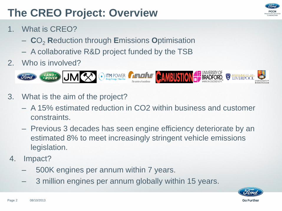
The CREO Project: Overview
1. What is CREO?
– CO2 Reduction through Emissions Optimisation
– A collaborative R&D project funded by the TSB
2. Who is involved?
3. What is the aim of the project?
– A 15% estimated reduction in CO2 within business and customer
constraints.
– Previous 3 decades has seen engine efficiency deteriorate by an
estimated 8% to meet increasingly stringent vehicle emissions
legislation.
4. Impact?
– 500K engines per annum within 7 years.
– 3 million engines per annum globally within 15 years.

08/10/2013 Page 3
The CREO Project: Overview (cont’d.)
5. How will CREO achieve its aim?
– re-design the engine and exhaust after-treatment as a complete system,
meeting all the legislative, customer and business requirements while
minimising the CO2 levels.
6. Specific goals?
i. The use of novel exhaust after-treatment techniques.
ii. The on-board generation and use of hydrogen.
iii. The development and application of new emissions optimisation tools.
• Jaguar Land Rover – led gasoline workstream.
• Ford – led diesel workstream.
+
This work is concerned with the Ford path and will describe how
MATLAB has been used to help develop an emissions optimisation
process.
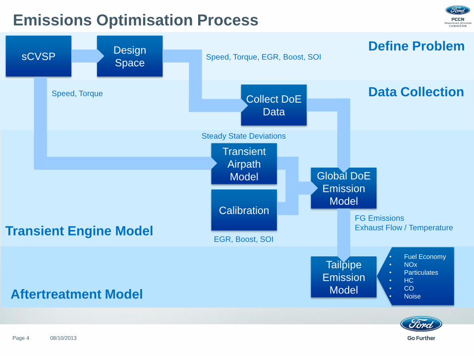
Emissions Optimisation Process
08/10/2013 Page 4
sCVSP
Collect DoE
Data
Design
Space
Transient
Airpath
Model Global DoE
Emission
Model Calibration
Tailpipe
Emission
Model
Define Problem
Data Collection
Transient Engine Model
Aftertreatment Model
• Fuel Economy
• NOx
• Particulates
• HC
• CO
• Noise
Speed, Torque
Speed, Torque, EGR, Boost, SOI
EGR, Boost, SOI
FG Emissions
Exhaust Flow / Temperature
Steady State Deviations
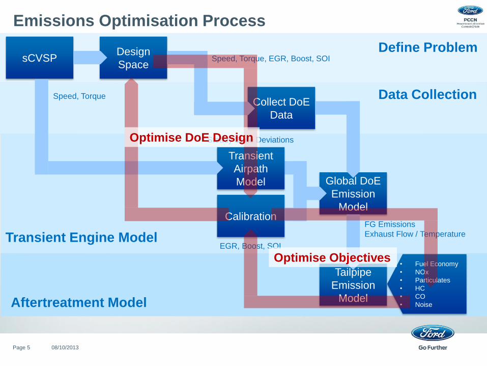
Emissions Optimisation Process
08/10/2013 Page 5
sCVSP
Collect DoE
Data
Design
Space
Transient
Airpath
Model Global DoE
Emission
Model Calibration
Tailpipe
Emission
Model
Define Problem
Data Collection
Transient Engine Model
Aftertreatment Model
• Fuel Economy
• NOx
• Particulates
• HC
• CO
• Noise
Speed, Torque
Speed, Torque, EGR, Boost, SOI
EGR, Boost, SOI
FG Emissions
Exhaust Flow / Temperature
Steady State Deviations Optimise DoE Design
Optimise Objectives
08/10/2013 Page 6
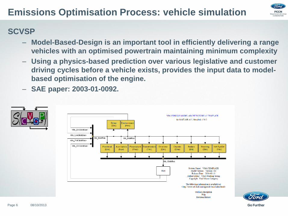
Emissions Optimisation Process: vehicle simulation
SCVSP
– Model-Based-Design is an important tool in efficiently delivering a range
vehicles with an optimised powertrain maintaining minimum complexity
– Using a physics-based prediction over various legislative and customer
driving cycles before a vehicle exists, provides the input data to model-
based optimisation of the engine.
– SAE paper: 2003-01-0092.
08/10/2013 Page 7
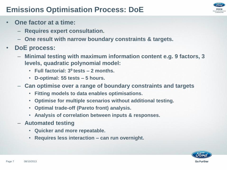
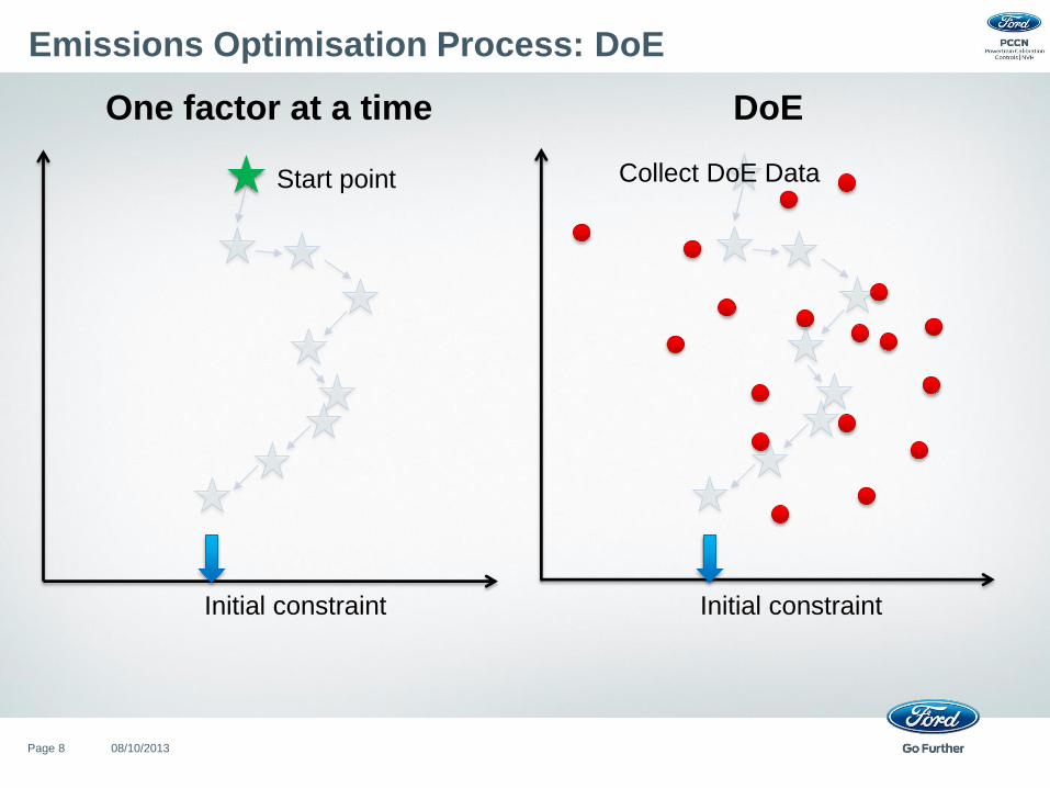
Emissions Optimisation Process: DoE
• One factor at a time:
– Requires expert consultation.
– One result with narrow boundary constraints & targets.
• DoE process:
– Minimal testing with maximum information content e.g. 9 factors, 3
levels, quadratic polynomial model:
• Full factorial: 39 tests – 2 months.
• D-optimal: 55 tests – 5 hours.
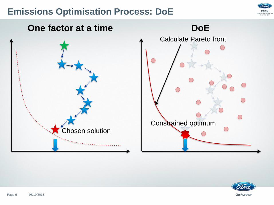
– Can optimise over a range of boundary constraints and targets
• Fitting models to data enables optimisations.
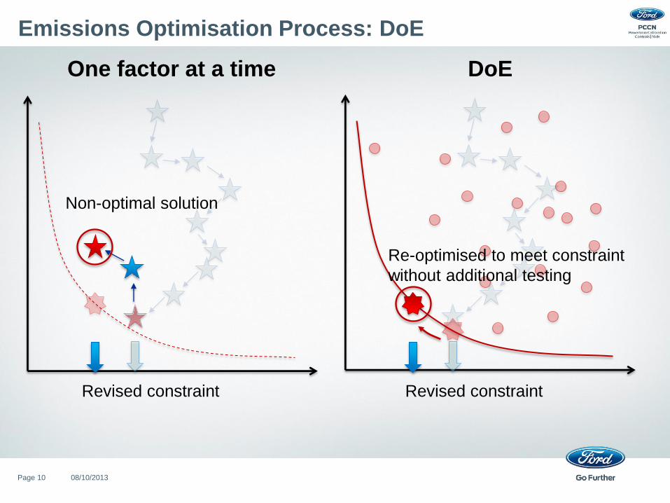
• Optimise for multiple scenarios without additional testing.
• Optimal trade-off (Pareto front) analysis.
• Analysis of correlation between inputs & responses.
– Automated testing
• Quicker and more repeatable.
• Requires less interaction – can run overnight.
08/10/2013 Page 8
Emissions Optimisation Process: DoE
Initial constraint Initial constraint
Start point Collect DoE Data
One factor at a time DoE
08/10/2013 Page 9
Emissions Optimisation Process: DoE
One factor at a time DoE Calculate Pareto front
Constrained optimum Chosen solution
08/10/2013 Page 10
Emissions Optimisation Process: DoE
Revised constraint
One factor at a time DoE
Revised constraint
Non-optimal solution
Re-optimised to meet constraint
without additional testing
08/10/2013 Page 11
Emissions Optimisation Process: Local vs. Global DoE
• Local DoEs
– Point-by-point (time-weighted) cycle optimisation
• Can only evaluate model at discrete speed/load points
• Requires interpolation to get an accurate cycle prediction
– Requires accurate & repeatable dynamometer control
• Global DoEs
– Requires automated screening
– More efficient data collection
• Less points for the same speed/torque area
• Infinite speed/torque resolution – optimise to calibration breakpoints
– Enables transient analysis & optimisation
• Requirement for after-treatment optimisation
– Enables engine scaling / dimensionless modelling
08/10/2013 Page 12
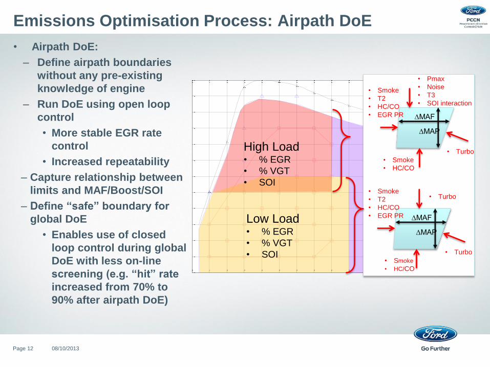
Emissions Optimisation Process: Airpath DoE
• Airpath DoE:
– Define airpath boundaries
without any pre-existing
knowledge of engine
– Run DoE using open loop
control
• More stable EGR rate
control
• Increased repeatability
– Capture relationship between
limits and MAF/Boost/SOI
– Define “safe” boundary for
global DoE
• Enables use of closed
loop control during global
DoE with less on-line
screening (e.g. “hit” rate
increased from 70% to
90% after airpath DoE)
750 1000 1250 1500 1750 2000 2250 2500 2750 3000 3250 3500 3750 40000
25
50
75
100
125
150
175
200
225
250
275
300
Speed [rev/min]
Torq
ue [
Nm
]
• Turbo
∆MAF
∆MAP
• Turbo
• Smoke
• T2
• HC/CO
• EGR PR
• Smoke
• HC/CO
∆MAF
∆MAP
• Smoke
• T2
• HC/CO
• EGR PR
• Pmax
• Noise
• T3
• SOI interaction
• Smoke
• HC/CO
• Turbo High Load • % EGR
• % VGT
• SOI
Low Load • % EGR
• % VGT
• SOI
08/10/2013 Page 13
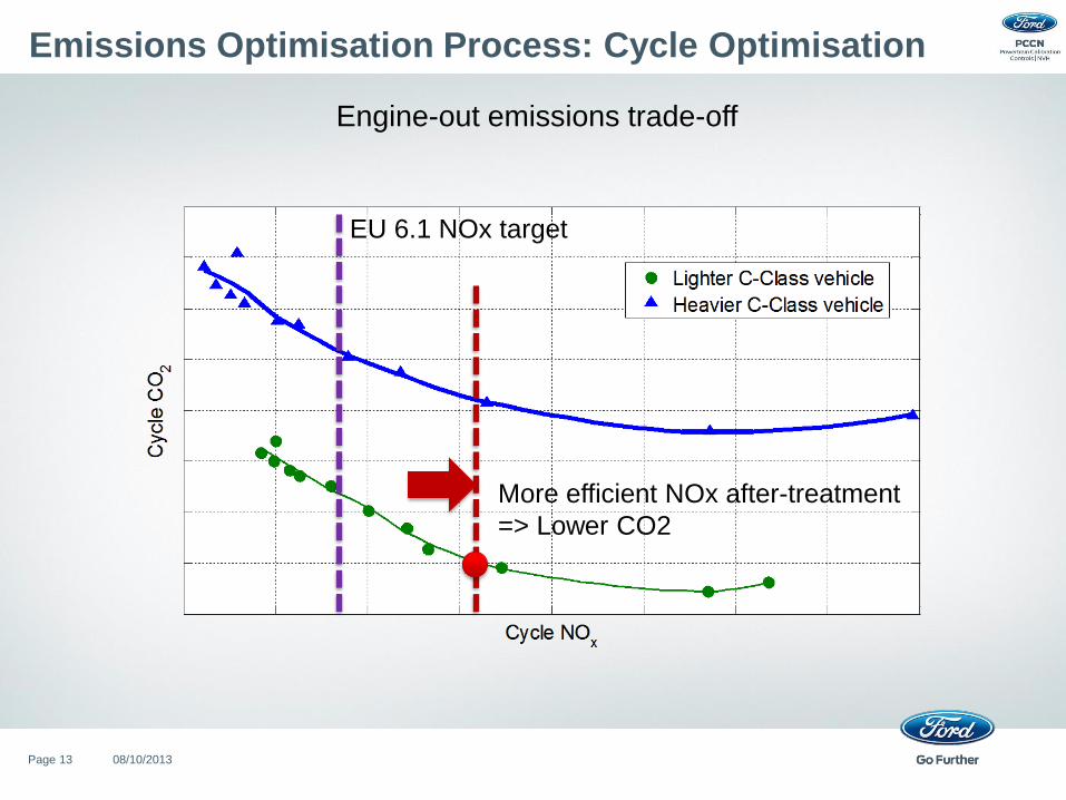
Emissions Optimisation Process: Cycle Optimisation
Engine-out emissions trade-off
More efficient NOx after-treatment
=> Lower CO2
EU 6.1 NOx target
08/10/2013 Page 14
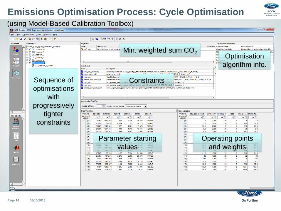
Emissions Optimisation Process: Cycle Optimisation
Constraints
Min. weighted sum CO2
Parameter starting
values
Operating points
and weights
Sequence of
optimisations
with
progressively
tighter
constraints
Optimisation
algorithm info.
(using Model-Based Calibration Toolbox)
08/10/2013 Page 15
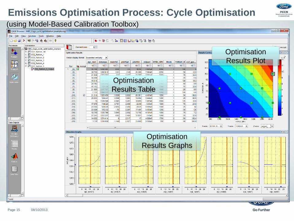
Emissions Optimisation Process: Cycle Optimisation
Optimisation
Results Table
Optimisation
Results Plot
Optimisation
Results Graphs
(using Model-Based Calibration Toolbox)
08/10/2013 Page 16
Emissions Optimisation Process: Cycle Optimisation
Next Steps:
• Currently experimenting with a multi-objective genetic algorithm to:
– Generate the Pareto-optimal front in one run.
– More exhaustively search the decision variable space.
– Reduced sensitivity (vs. gradient-based optimisers) to start position.
– Reduced sensitivity to getting stuck in local minima.
• This is a significant computing challenge due to the large number of
decision variables and may require:
– Large populations.
– Parallel computing.
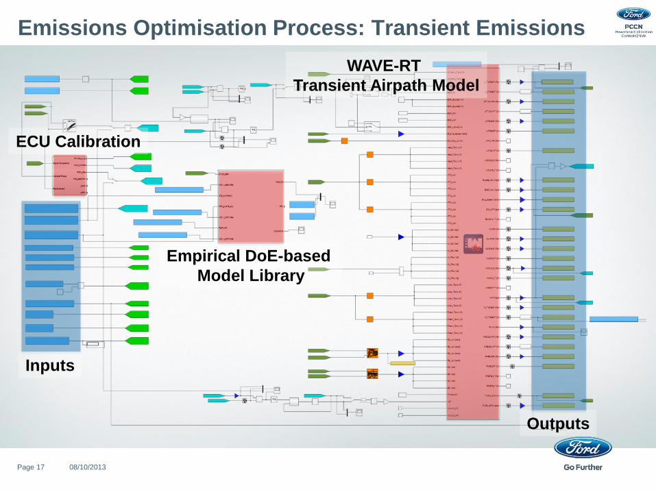
Emissions Optimisation Process: Transient Emissions
08/10/2013 Page 17
Empirical DoE-based
Model Library
WAVE-RT
Transient Airpath Model
ECU Calibration
Inputs
Outputs
08/10/2013 Page 18
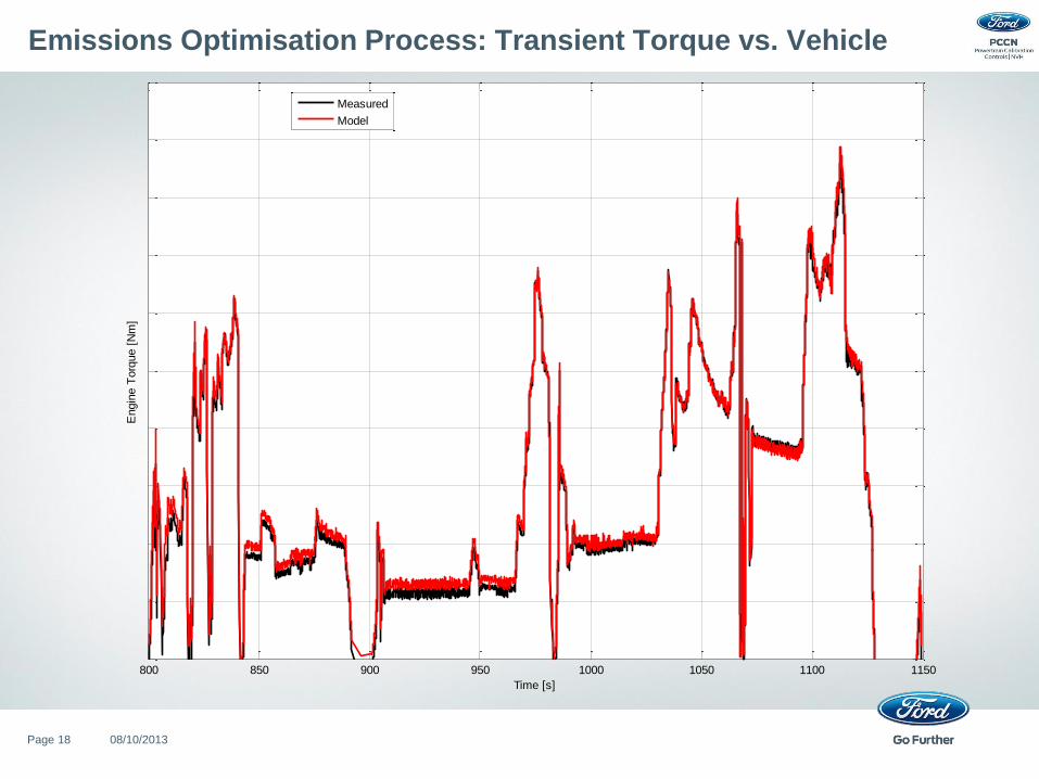
Emissions Optimisation Process: Transient Torque vs. Vehicle
800 850 900 950 1000 1050 1100 1150
Engin
e T
orq
ue [
Nm
]
Time [s]
Measured
Model
08/10/2013 Page 19
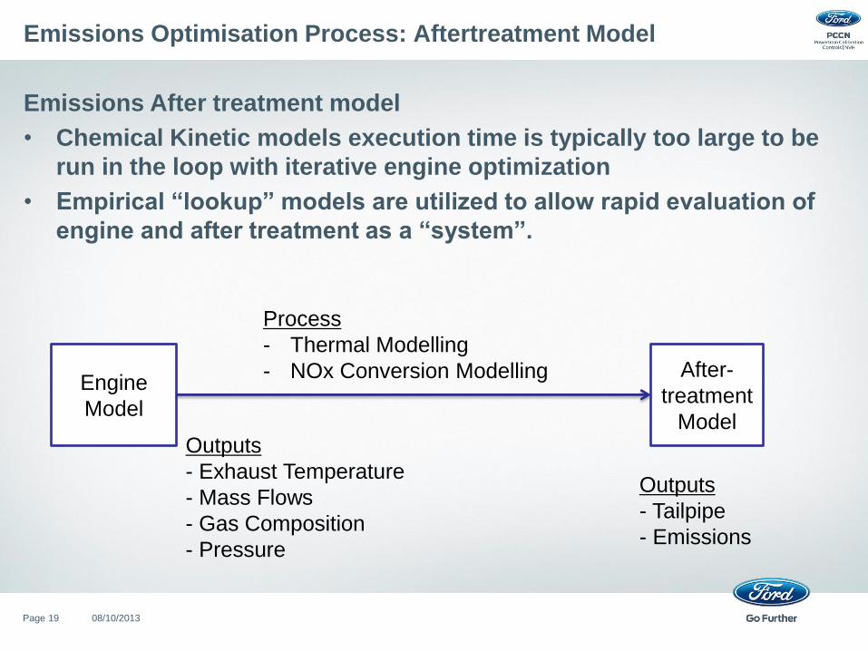
Emissions Optimisation Process: Aftertreatment Model
Emissions After treatment model
• Chemical Kinetic models execution time is typically too large to be
run in the loop with iterative engine optimization
• Empirical “lookup” models are utilized to allow rapid evaluation of
engine and after treatment as a “system”.
Engine
Model
After-
treatment
Model Outputs
- Exhaust Temperature
- Mass Flows
- Gas Composition
- Pressure
Outputs
- Tailpipe
- Emissions
Process
- Thermal Modelling
- NOx Conversion Modelling
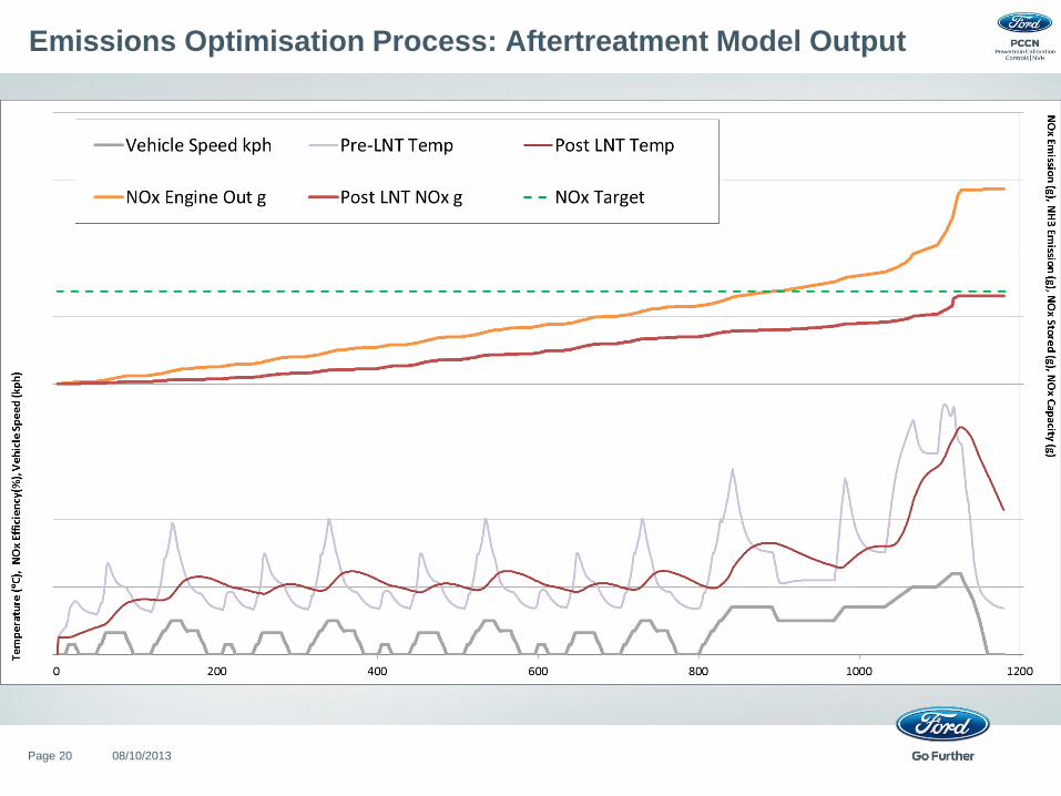
Emissions Optimisation Process: Aftertreatment Model Output
08/10/2013 Page 20
Summary
• A model-based emissions optimisation process has been developed in
the MATLAB/Simulink environment.
• This process has yielded fuel economy improvements as well as
time/cost efficiencies.
• Furthermore, it enables:
– Full exploration of the design space for any fuel economy gains.
– ‘What-If’ studies to explore design and calibration opportunities.
– Robustness studies using optimisation to explore the impact of real-world
noise sources (wear, manufacturing, environment, customer usage).
• Further work to be done includes development of:
– Better correlation of emissions models.
– Optimisation capability for high-dimensional problems.
– Further process automation.
– User interfaces.
08/10/2013 Page 21