Difusor de Plastico Bi-Radial com Garganta de 1" - Manual Sonigate

A WHITE PAPER DESCRIBING THE INTERNAL COMBUSTION ENGINE’S
FINAL IMPROVEMENT
THE COUNTERPOISE BI-RADIAL ENGINE
Authored by
Del Wolverton Chief Science Officer/Founder
WolvertonBailey Innovations, Inc.
SUMMARY
This is the year that we celebrate 140 years since Dr. Nikolas Otto patented the four-stroke internal combustion engine in 1877. His gasoline engine serves as the origin of the “Otto Cycle” which is used as the basis for the six internal combustion engine variants today.
For purposes of this white paper, the 4-cylinder Otto engine will be used as the “reference engine.” Since Dr. Otto’s engine was built around the origin of the 4-stroke-cycle of the pistons, this allows us to have a piston per cycle. Many changes have taken place during the past century in the size and shape of the engine as designed for various uses, however, this original 4-stroke cycle is still used in the latest internal combustion engine just patented in 2016.
The discussion in this white paper will first describe the Otto Cycle, providing a simple, math-free description of each of the four strokes. Then, in order to help understand the operation, power, and weight advantages gained in the evolution, the author will then take you through the five existing variants, plus the newly patented latest and final design improvement—the Counterpoise Bi-Radial Engine.
CONTENTS
Single-Piston of the Otto Cycle ..................................................................................................... 2 The 4 Strokes ................................................................................................................................ 2 Intake ....................................................................................................................................... 2 Compression ............................................................................................................................ 3 Power ....................................................................................................................................... 4 Exhaust .................................................................................................................................... 5 Four-Cylinder Engine .................................................................................................................... 6 Four-Cylinder Boxer Engine .......................................................................................................... 7 Eight-Cylinder Engine (V8) ........................................................................................................... 8 Radial Engine ................................................................................................................................ 9 Rotary Engine ............................................................................................................................. 10 Bi-Radial Engine ......................................................................................................................... 11 Counterpoise Bi-Radial Engine ................................................................................................... 12 Conclusion .................................................................................................................................. 13

2 of 13
SINGLE-PISTON OF THE OTTO CYCLE
If we analyze how a single piston develops power, we can use it as a standard throughout our descriptions. Further, that piston can be used as a building block to explain all of the following engine types.
THE 4 STROKES
In the following series of pictures, a crankshaft is shown moving a piston downward in a shaded block called a bore assembly. The red arrows show the motion of the piston from the beginning of the cycle and the red arc indicates the motion of the crankshaft. Further discussions will use the term cylinder to refer to both the pistons and the bore assembly as a unit.
INTAKE (First Down-Stroke)
Intake Stroke – Breathing in a mixture of air and fuel.
Without considering the intake valves, the exhaust valves, and other common engine parts, it can be said that the first half rotation of the crankshaft moves the piston down a chamber, creating a void which, when compared to atmospheric pressure, causes an inrush of air and fuel to fill the void. When the piston reaches the bottom of the stroke, the container is closed, and the next stroke is ready to begin.

3 of 13
The end of the first stroke leaves the piston at the bottom of the void with a volatile mixture ready to ignite. However, this would not accomplish anything useful, as burning the fuel at this point would create a great deal of heat and expanding gases with nowhere to go.
COMPRESSION (First Up-Stroke) Compression Stroke – Squeeze the mixture while it is cool. As the crankshaft continues for another half rotation as shown above, the piston is forced back up the chamber and compresses the mixture of air and fuel into a very small portion of the void. How much it is compressed is called the Compression Ratio and is determined by the length of the void as compared to the motion of the piston. Three things are accomplished by the compression of the mixture, the first being that the piston will be at the top of the void ready to move back down in the next stroke. The second is that the mixture of air and fuel will become very hot as it is compressed due to the nature of pressure and temperature with regard to gasses. The third thing to happen is that the pressure inside the void will be multiplied by the Compression Ratio (in pounds per square inch, for example.) For ease of explanation, we can now see that in one revolution of the crankshaft we have prepared the void to ignite a volatile, compressed mixture, such that there is room for the piston to move if we increase the pressure inside the void. The Otto Cycle is now halfway through and the engine design takes into consideration that there now needs to be a quick ignition of the mixture. Many things determine exactly when this will happen in a modern engine, but for this discussion, the time to ignite is NOW!
4 of 13
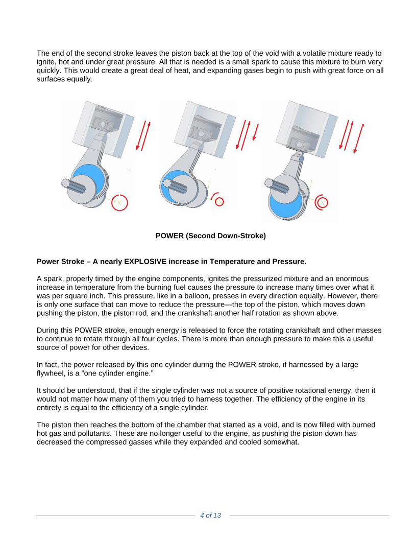
The end of the second stroke leaves the piston back at the top of the void with a volatile mixture ready to ignite, hot and under great pressure. All that is needed is a small spark to cause this mixture to burn very quickly. This would create a great deal of heat, and expanding gases begin to push with great force on all surfaces equally.
POWER (Second Down-Stroke) Power Stroke – A nearly EXPLOSIVE increase in Temperature and Pressure. A spark, properly timed by the engine components, ignites the pressurized mixture and an enormous increase in temperature from the burning fuel causes the pressure to increase many times over what it was per square inch. This pressure, like in a balloon, presses in every direction equally. However, there is only one surface that can move to reduce the pressure—the top of the piston, which moves down pushing the piston, the piston rod, and the crankshaft another half rotation as shown above. During this POWER stroke, enough energy is released to force the rotating crankshaft and other masses to continue to rotate through all four cycles. There is more than enough pressure to make this a useful source of power for other devices. In fact, the power released by this one cylinder during the POWER stroke, if harnessed by a large flywheel, is a “one cylinder engine.” It should be understood, that if the single cylinder was not a source of positive rotational energy, then it would not matter how many of them you tried to harness together. The efficiency of the engine in its entirety is equal to the efficiency of a single cylinder. The piston then reaches the bottom of the chamber that started as a void, and is now filled with burned hot gas and pollutants. These are no longer useful to the engine, as pushing the piston down has decreased the compressed gasses while they expanded and cooled somewhat.
5 of 13
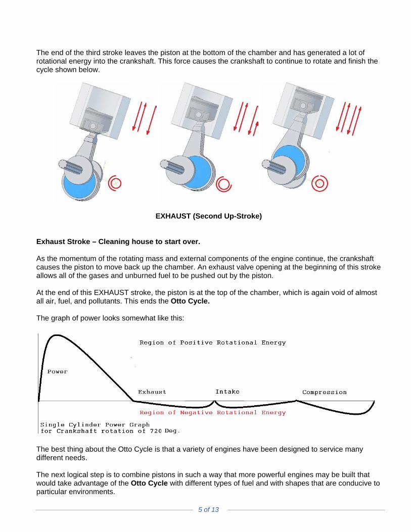
The end of the third stroke leaves the piston at the bottom of the chamber and has generated a lot of rotational energy into the crankshaft. This force causes the crankshaft to continue to rotate and finish the cycle shown below.
EXHAUST (Second Up-Stroke) Exhaust Stroke – Cleaning house to start over. As the momentum of the rotating mass and external components of the engine continue, the crankshaft causes the piston to move back up the chamber. An exhaust valve opening at the beginning of this stroke allows all of the gases and unburned fuel to be pushed out by the piston. At the end of this EXHAUST stroke, the piston is at the top of the chamber, which is again void of almost all air, fuel, and pollutants. This ends the Otto Cycle. The graph of power looks somewhat like this:
The best thing about the Otto Cycle is that a variety of engines have been designed to service many different needs. The next logical step is to combine pistons in such a way that more powerful engines may be built that would take advantage of the Otto Cycle with different types of fuel and with shapes that are conducive to particular environments.

6 of 13
4-CYLINDER OTTO ENGINE (this will be our “reference engine”) Starting with an engine that has only one piston currently in each of the four cycles, it is clear that we would need four pistons so that a power stroke was always taking place.
4-Cylinder Otto Engine (Multiple Piston Otto Cycle) The most common configuration of the Otto Cycle engine is the simple “four banger” because of the minimum number of parts for the required cycles to be most productive. Four identical cylinders are aligned on a common crankshaft and if each cylinder starts the Otto Cycle a half stroke behind the previous cylinder, there will always be a POWER stroke taking place during each of the four cycles.
This engine is the “reference engine” for our discussion, as it provides a power stroke for each of the four cycles. In fact, because there are four cycles and four pistons, each cycle is always taking place. There is a constant vacuum on the intake and a constant output at the exhaust. There is also a constant drag on the engine from the compression taking place—two power strokes per revolution of the crankshaft! Only the POWER stroke is shown above as it overpowers the losses of the other strokes. Engines can be designed for a variety of fuels, including some fuels that ignite at lower temperatures. In 1864, Nikolaus Otto patented the first Atmospheric Gas Engine. Rudolf Diesel patented the Diesel Engine, as a higher efficiency version of this engine in 1892.

7 of 13
4-CYLINDER BOXER ENGINE A very popular configuration of the Otto Cycle engine is the “Boxer” because of the minimum size and easy layout of parts for the required cycles to be completely productive.
4-Cylinder Boxer Engine Here, the drawing shows that if you rotate two cylinders to the left and two cylinders to the right, the new configuration should have exactly the same power as the “reference engine.” Power in an Otto Cycle engine is primarily determined by the size of the VOID, or “displacement” of the piston. Just like the “reference engine,” if each cylinder starts the Otto Cycle a half stroke behind the previous cylinder, the combined output will always have a POWER stroke taking place as shown:
Every thing we discovered about the “reference engine” is true for the “Boxer” as well. Again, since the POWER stroke is so powerful, it is overpowering the losses of the other strokes. A reduction in the depth of the engine is possible because there are two pistons on each side of the center crankshaft. This will have the effect of reducing weight, while maintaining the same power. This, coupled with other advantages, makes the “Boxer” a very popular small automobile engine. Like the “reference engine,” this engine has two power strokes per revolution of the crankshaft. In 1896, Karl Benz invented the first engine with horizontally opposed pistons called the Boxer.

8 of 13
8-CYLINDER V8 OTTO ENGINE A very powerful configuration of the Otto Cycle engine is the “V8” because of the extra set of four pistons to increase the number of power strokes per revolution of the crankshaft. It is a bit more efficient on a power-to-weight ratio.
8-Cylinder V8 Otto Engine Here, the drawing shows that if you rotate four cylinders to the left, and add four cylinders to the right, the new configuration should have exactly twice the power of the “reference engine.” Notice that the V8 looks like two “four bangers” connected with a 90-degree offset. However, unlike the “reference engine,” each cylinder starts the Otto Cycle a quarter stroke behind the previous cylinder, the combined output will always have TWO POWER strokes taking place per cycle, as shown:
Because there are twice as many cylinders, there are twice as many pulses of power per rotation of the crankshaft. This increases the output power by a factor of two to one, as well as smoothing out the torque on the crankshaft. During light loads, the V8 requires less energy from each piston, but is not as efficient as the “reference engine.” Unlike the “reference engine,” this engine has four power strokes per revolution of the crankshaft. Leon Levasseur patented the first V8 engine in 1902, originally named the “Antoinette.”

9 of 13
RADIAL ENGINE An interesting configuration of the Otto Cycle engine is the “Radial Engine,” designed for minimum depth and airflow cooling. This engine was designed as a power plant for aircraft.
Radial Engine (Rotating Crankshaft) Here, the drawing shows that if you rotate one cylinder to the left, one cylinder to the right, and one cylinder to the bottom from the “reference engine,” the new engine configuration should have exactly the same power as the “reference engine.”
Every thing we discovered about the “reference engine” is true for the “Radial Engine” as well. Again, since the POWER stroke is so powerful, it is overpowering the losses of the other strokes. A reduction in the depth of the engine is possible because there are four pistons on each side of the center crankshaft. This will have the effect of reducing the weight, while maintaining the same power. Like the “reference engine,” this engine has two power strokes per revolution of the crankshaft. However, the depth of the engine is only one cylinder, as they all share the same crankshaft offset. The crankshaft rotates and forces the pistons to do exactly what was done in the “reference engine.” Like the “reference engine,” this engine has two power strokes per revolution of the crankshaft.

10 of 13
ROTARY ENGINE Similar to the “Radial Engine,” the “Rotary Engine” has four cylinders around a single crankshaft.
Rotary Engine (Rotating Body) Here, just like the “Radial Engine” there is one cylinder on the top, one cylinder on the left, one cylinder on the right, and one cylinder on the bottom, the new configuration should have exactly the same power as the “reference engine” also.
Every thing we discovered about the “Radial Engine” is also true for the “Rotary Engine.” However, in this configuration, instead of rotating the crankshaft, the crankshaft is stationary and we rotate the bore assembly around it. Unlike any engine so far, the pistons do not move up and down. Instead, they follow a circular path within the rotating bore assembly, causing them to appear to function the same. However, the rapid change in direction has been cut in half. This reduces the energy required by the piston motion and provides a slight increase in efficiency. Felix Millet patented the 5-Cylinder rotary engine using the Otto Cycle in 1889 and it was put into production in 1900.

11 of 13
BI-RADIAL ENGINE Unlike the “reference engine,” this engine has four power strokes per revolution of the bore assemblies. Combining the “Radial Engine” and the “Rotary Engine,” the “Bi-Radial Engine” has four cylinders around a single crankshaft. In this case, the crankshaft rotates, as well as the bore assemblies, but in the opposite direction. It is like superimposing the two engines on each other, giving you double the power strokes.
Bi-Radial Engine (Rotating Crankshaft and Body) Here, the drawing shows that if you have a radial engine superimposed on a rotary engine, the new configuration should have twice the power as the “reference engine,” if measured for a full 720 degrees, because there will be two power strokes per cylinder.
Unlike any engine so far, the pistons follow an oval path within the rotating bore assembly causing them to appear to have twice the function of the “reference engine,” and provide power every time around. Therefore, it can be seen that a four-cylinder engine acts like an eight-cylinder engine for the same 720 degrees of crankshaft rotation. Siemens-Halske developed the Bi-Radial Engine toward the end of WWII.

12 of 13
COUNTERPOISE BI-RADIAL ENGINE (The Last Modification)
Counterpoise Bi-Radial Engine (Rotating Crankshaft and Body) Similar to the “Siemens-Halske Bi-Radial Engine,” the “Counterpoise Bi-Radial Engine” has four cylinders around a single crankshaft and the crankshaft rotates as well as the bore assembly. Here, a brand-new configuration draws on the benefits of the Bi-Radial Engine, with a reduction of piston flap, an oval path, and a power stroke per revolution. It will have at least twice the power as the “reference engine,” but wait… there’s more.
Unlike any engine so far, the bore assemblies are at an angle, such that the pressure on the ceiling of the bore is pushing the bore in the desired direction to aid the output torque of the engine. This has never been accomplished before. Since the pressure on the piston and the ceiling of the bore are the same, the available torque is captured twice. Unlike the “reference engine,” this engine has four power strokes per revolution and unlike any other engine, manages to capture the energy on the ceiling of the bore. D. Wolverton and D. Bailey patented the Counterpoise Engine in 2015. It is the only engine in existence that fits this category.

13 of 13
CONCLUSION The design path from the first Otto engine through the various rotaries and radials has shown that the Counterpoise Bi-Radial Engine is the last and final process of squeezing the most energy out of a tank of gasoline. There are also a few additional specifics that were overcome in the transitions. Both the Radial Engine and the Rotary Engine were found to function smoothly, only when there were an odd number of cylinders. It takes just a quick look at the diagrams on pages 9 and 10 to realize that if a piston is going to have a power stroke every other rotation of the crankshaft, then the series would have to be: Fire 1 Skip 2 Fire 3 Skip 4 …and repeat. It would also follow that you need to Fire 1 again (next)—except that cylinder 1 fired last rotation and needs to do an exhaust stroke this time. The solution is to add a 5th cylinder, such that you then have a firing order of: Fire 1 Fire 3 Fire 5 Fire 2 Fire 4 …and repeat. In addition to the firing order dilemma, the engines are also very unbalanced because all of the pistons are traversing the crankshaft, which is moving in a circle about the center of the engine. This is an unbalanced mass with vibration issues and was not overcome in the prior radial type engines. In the Counterpoise Bi-Radial Engine, the sets of two pistons are balanced against each other, moving in opposite directions from each other, because of the unique design of the crankshaft. The oval path of the cylinders and the sequence of firing the charged mixture permit the Counterpoise Bi-Radial Engine to fire at the top of the engine, each and every time it reaches the top. Every cylinder, in order, fires at the top and then has the three additional cycles before it reaches the top again. Thus, the Counterpoise Bi-Radial Engine is the first of this type of engine that can maintain dynamic balance with an even number of cylinders. With all of the above, it is shown that this engine is the lightest, highest torque engine ever designed. The size can be adjusted for torque, weight, or fuel efficiency. Indeed, the conclusion regarding the Counterpoise Bi-Radial Engine would be a higher efficiency engine with more torque, less weight, and lower emissions than any engine ever designed. Contact information: Pamela L. Summers, Public Relations Director, WolvertonBailey Inc., Santa Rosa, CA, [email protected] © WolvertonBailey Inc. 2017 All rights reserved. Counterpoise Engine, US Patent # US 9,074,527, B2 on July 7, 2015.