The Completely Inelastic Bouncing Ball -...
26
The Completely Inelastic Bouncing Ball November 2011 N. Arora, P. Gray, C. Rodesney, J. Yunis
-
Upload
vuongduong -
Category
Documents
-
view
222 -
download
0
Transcript of The Completely Inelastic Bouncing Ball -...

The Completely Inelastic Bouncing Ball
November 2011
N. Arora, P. Gray, C. Rodesney, J. Yunis

2
Completely Inelastic Bouncing Ball?
• Can there be an inelastic bouncing ball?
YES!
The plate is driven periodically in the vertical direction
The ball is constrained to move vertically
The ball can “take off” when the acceleration of the plate exceeds the acceleration due to gravity

3
Background
• Mehta and Luck (1990)
– Partially resolved the motion
• Gilet, et. al. (2009)
– Presented a complete analytical resolution of the inelastic bouncing ball on a sinusoidally forced plate.
Trajectory of the Ball in Time Bifurcation Diagram 3

4
Governing equations
Position of plate Time Driving Frequency
Amplitude Ratio of Frequencies (integer)
Threshold for Takeoff
Time When the Ball Takes Off
4

5
Non-Dimensionalized Equations
Phase: Generalized Position: Reduced Acceleration:
New set of governing equations:
New takeoff condition:
5

6
Time of flight
Time of flight is defined as:
Flight time is determined by solving numerically when F=0:
6

7
Computational models
C=1 C=2
C=3 7

8
Computational models
C=1 C=2
C=3
8

9
Initial Setup
• Position data provided by accelerometer on platform
– Ball takes off when Fplate > Fg
– Ball lands when accelerometer detects impact
• Problems:
– Noisy accelerometer signal
• When ball lands while plate is descending, there may be little additional acceleration
– Ball not constrained to 1D movement
Sand filled “inelastic”
ball
Plastic cage to constrain ball
0
+x
-x Spring –isolated
Shaker
9
Power Amp Shaker Lab View
Signal
Generator
Accel. Output

10
Reconfigured Setup
• Position data provided circuit contact (tin foil)
– Ball takes off when v= 5.0 V
– Ball lands when shorted to ground
• No noise in flight time signal
Accel. Output
Labview
ShakerPower Ampr
Signal Generator
+5.0 V
Ball
Metal block with bearings
Pole to constrain to 1D
Electrical leads
Spring –isolated Shaker
0
+x
-x
10

11
Reconfigured Setup
11

12
Issues with Setup
• Friction
• Twisting of mass
• Not truly inelastic
• Shaker oscillation at high Γ
12

13
Without friction With friction 13
Friction
• Coulomb Friction due to ball sliding over the post
– Experimentally determined the frictional acceleration by a drop test
– Constant frictional acceleration of ~0.3 g found via fitting a parabola
– Friction modeled as a constant force acting in the opposite direction to the relative velocity of the ball and plate
1
0.5

14
Whoa! Looks like they match!
0 10 20 30 40 50 60-10
0
10
20
30
40
50
14

15
Data Acquisition
• Data was taken at a sample rate of 20 KHz
• Two channels were read in to LabView
– Acceleration
– Voltage from continuity sensor
• Data output in tab delimited format to text file with two additional columns
– Time
– Acceleration due to the impact of the ball
Accelerometer
Continuity
Time
Acceleration
Continuity
Data.txt
15

16
• For a given frequency, gamma was varied by ramping up the amplitude of vibration to generate accelerations from 1g to 8g.
• Lab View took very small steps to increase the amplitude lingering at each amplitude
– The number of periods to wait before increasing the amplitude was given by the user.
– Values from 5 to 60 were experimented with.
• Each step represents a part of the bifurcation diagram.
4.4 4.6 4.8 5 5.2 5.4
-0.6
-0.4
-0.2
0
0.2
0.4
0.6
Time (s)
Accele
ration (
g)
Acceleration and Imact Signal
3 4 5 6 7 8 9 10 11
-2
-1.5
-1
-0.5
0
0.5
1
1.5
2
Time (s)
Accele
ration (
g)
Acceleration and Imact Signal
16
Data Acquisition

17
• Matlab was used to visualize and analyze the data.
0 100 200 300 400 500 600 700-4
-3
-2
-1
0
1
2
3
4
Time (s)
Accele
ration (
g)
Acceleration and Imact Signal
0 100 200 300 400 500 600 700-10
-8
-6
-4
-2
0
2
4
6
8
Time (s)
Accele
ration (
g)
Impact Signal
309.2 309.4 309.6 309.8 310 310.2 310.4 310.6 310.80
0.5
1
1.5
2
2.5
3
3.5
4
4.5
5
Time (s)
Voltage (
V)
Continuity Singal
17
• The “reshape” command was used to reshape the data such that each step of constant amplitude could be analyzed independently.
• TOF for determined for each constant amplitude group
• The first TOF values were ignored steady state response was considered and not the transient response.
• Plotting the TOF values for each amplitude gives the bifurcation diagram.
Data Acquisition

18
Bifurcation Diagram
• The full bifurcation diagram ranges from 1 to 8g.
• Contains regions of period doubling bifurcations as well as forbidden regions
0 1 2 3 4 5 6 7 8 90
500
1000
1500
2000
2500
3000
3500
4000
4500Full Bifurcation Diagram
Gamma
TO
F
18

19
Data Analysis
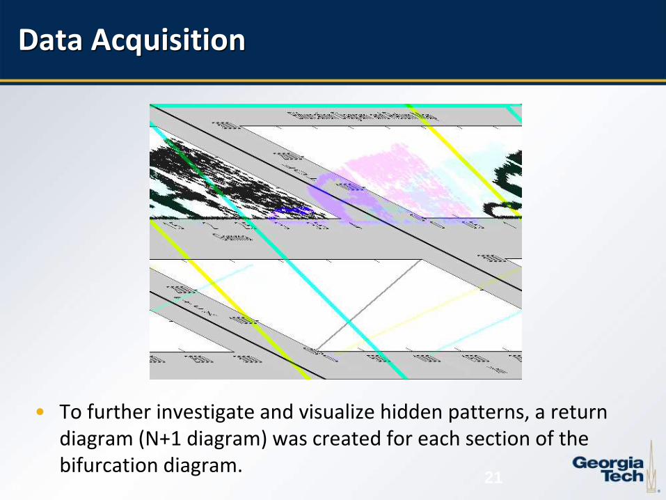
• To further investigate and visualize hidden patterns, a return diagram (N+1 diagram) was created for each section of the bifurcation diagram.
19

20
• More data was taken at lower gamma values due to reduction in flight times introducing less error into the test.
0 0.5 1 1.5 2 2.5 3 3.5 40
500
1000
1500
2000
2500
3000Full Bifurcation Diagram
Gamma
TO
F
20
Data Acquisition
21
• To further investigate and visualize hidden patterns, a return diagram (N+1 diagram) was created for each section of the bifurcation diagram.
21
Data Acquisition

22
• TOF values from the measured bifurcation diagrams were compared to the published results and model predictions.
• Measured TOF values were seen to be significantly lower than the predicted values.
• General shape of bifurcation diagrams seem to be similar
0 1 2 3 4 5 6 7 8 90
500
1000
1500
2000
2500
3000
3500
4000
4500Full Bifurcation Diagram
Gamma
TO
F
22
Data Acquisition

23
Other Sources of Model Error
23
• Elasticity in the bouncing ball
• Plate idle feedback, altering the time of flights especially during high g inputs
• Uneven collision between the shaker and the ball during the impact
• Ball rotation observed at higher g inputs may be attributed to the torqueing previously discussed

24
Conclusion
Successfully studied the behavior of a completely inelastic bouncing ball on a vibrating plate subjected to a sine based input forcing function
Attempt has been made to model the Coulomb friction in the theoretical model.
Experimentally validated the bifurcation pattern, the pattern is closely matched but the actual time flights are off.
Discrepancy in absolute values attributed to possible sources of error like friction, plate idle feedback, torqueing impact of the ball and elasticity of the bouncing ball.
24

25
Future Work
Implement a variety of input forcing functions for experimental analysis
Improving the experimental setup by correcting torqueing at impact and minimizing the plate idle feedback.
Modeling of the elasticity of the “ball” used for this current experiment.
25

26
Questions
26