The complete guide to PRESSURE AND VACUUM · PDF fileThe complete guide to PRESSURE AND VACUUM...
22
THE EXPERIENCE AND INGENUITY TO MEET ANY APPLICATION REQUIREMENTS... THE EXPERIENCE AND INGENUITY TO MEET ANY APPLICATION REQUIREMENTS... CALL US OR VISIT OUR WEBSITE TO REQUEST OTHER CONAX BUFFALO CATALOGS: CALL US OR VISIT OUR WEBSITE TO REQUEST OTHER CONAX BUFFALO CATALOGS: Standard sealing assemblies are generally available from stock. Unlimited custom designs are available for virtually any probe or wire sealing application. For more information and for assistance with gland selection and application engineering advice, contact your Conax ® Buffalo Technologies representative. The standard ranges of sealing assemblies shown in this brochure can be customised through the use of other materials for gland bodies, the choice of special sealant materials and by specifying optional mounting and cap threads. In addition to these variations we also design glands for non-threaded mounting. In most cases, our wide variety of off-the-shelf products can be adapted to meet the needs of your application. For those truly unique requirements and for specific applications where standard glands, or modified versions, cannot meet customers’ specifications, our engineers are ready to put more than 50 years of experience to work designing the perfect solution for your application. Many of our custom designs are now industry standards. Our knowledgeable, experienced staff would welcome the opportunity to discuss your application and recommend solutions. 2300 Walden Avenue Buffalo, New York 14225, USA Fax: 1-716-684-7433 • Phone: 1-716-684-4500 Toll free in the USA at 1-800-223-2389 Teflon and Kapton are registered trademarks of E I Du Pont de Nemours Company • Viton is a registered trademark of DuPont Dow Elastomers LLC Grafoil is a registered trademark of the UCAR Carbon Company ©2005 Conax ® Buffalo Technologies Catalog 6102 EUR 11/05 The complete guide to PRESSURE AND VACUUM SEALING ASSEMBLIES The complete guide to PRESSURE AND VACUUM SEALING ASSEMBLIES Feedthrough glands for sensors, probes, electrodes, wires, wire bundles and optical fibres Feedthrough glands for sensors, probes, electrodes, wires, wire bundles and optical fibres 50 YEARS EXPERIENCE • OEM Supplier to GE • Aftermarket Supplier 50 YEARS EXPERIENCE • OEM Supplier to GE • Aftermarket Supplier Highly Reliable Temperature Sensors and Seals for the PowerGen Industry
Transcript of The complete guide to PRESSURE AND VACUUM · PDF fileThe complete guide to PRESSURE AND VACUUM...

THE EXPERIENCE AND INGENUITY TO MEET ANY APPLICATION REQUIREMENTS...THE EXPERIENCE AND INGENUITY TO MEET ANY APPLICATION REQUIREMENTS...
CALL US OR VISIT OUR WEBSITE TO REQUEST OTHER CONAX BUFFALO CATALOGS:CALL US OR VISIT OUR WEBSITE TO REQUEST OTHER CONAX BUFFALO CATALOGS:
Standard sealing assemblies are generally available from stock.Unlimited custom designs are available for virtually any probe orwire sealing application.
For more information and for assistance with gland selectionand application engineering advice, contact your Conax® BuffaloTechnologies representative.
The standard ranges of sealing assemblies shown in this brochure can be customised through the use of other materials for gland bodies, the choice of special sealant materials and by specifyingoptional mounting and cap threads.
In addition to these variations we also design glands for non-threadedmounting. In most cases, our wide variety of off-the-shelf productscan be adapted to meet the needs of your application.
For those truly unique requirements and for specific applicationswhere standard glands, or modified versions, cannot meet customers’specifications, our engineers are ready to put more than 50 years ofexperience to work designing the perfect solution for your application.Many of our custom designs are now industry standards.
Our knowledgeable, experienced staff would welcome the opportunityto discuss your application and recommend solutions.
2300 Walden AvenueBuffalo, New York 14225, USAFax: 1-716-684-7433 • Phone: 1-716-684-4500Toll free in the USA at 1-800-223-2389
E-mail: [email protected]: www.conaxbuffalo.com
Teflon and Kapton are registered trademarks of E I Du Pont de Nemours Company • Viton is a registered trademark of DuPont Dow Elastomers LLCGrafoil is a registered trademark of the UCAR Carbon Company
©2005 Conax® Buffalo Technologies Catalog 6102 EUR 11/05
The complete guide toPRESSURE AND VACUUM SEALING ASSEMBLIES
The complete guide toPRESSURE AND VACUUM SEALING ASSEMBLIES
Feedthrough glands for sensors, probes, electrodes, wires, wire bundles and optical fibresFeedthrough glands for sensors, probes, electrodes, wires, wire bundles and optical fibres
50 YEARS EXPERIENCE • OEM Supplier to GE • Aftermarket Supplier50 YEARS EXPERIENCE • OEM Supplier to GE • Aftermarket Supplier
Highly Reliable Temperature Sensors and Sealsfor the PowerGen Industry
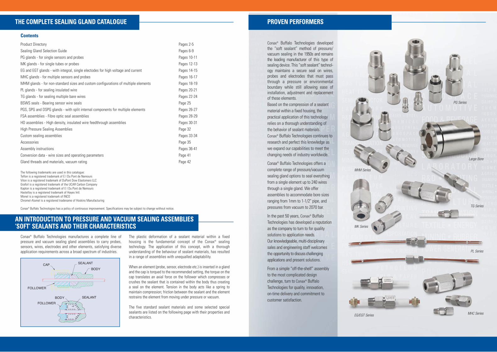
Conax® Buffalo Technologies developedthe “soft sealant” method of pressure/vacuum sealing in the 1950s and remainsthe leading manufacturer of this type ofsealing device. This “soft sealant” technol-ogy maintains a secure seal on wires,probes and electrodes that must passthrough a pressure or environmentalboundary while still allowing ease ofinstallation, adjustment and replacement of these elements. Based on the compression of a sealantmaterial within a fixed housing, thepractical application of this technologyrelies on a thorough understanding of the behavior of sealant materials. Conax® Buffalo Technologies continues toresearch and perfect this knowledge aswe expand our capabilities to meet thechanging needs of industry worldwide.
Conax® Buffalo Technologies offers acomplete range of pressure/vacuumsealing gland options to seal everythingfrom a single element up to 240 wiresthrough a single gland. We offerassemblies to accommodate bore sizesranging from 1mm to 1-1/2" pipe, andpressures from vacuum to 2070 bar.
In the past 50 years, Conax® BuffaloTechnologies has developed a reputationas the company to turn to for qualitysolutions to application needs. Our knowledgeable, multi-disciplinarysales and engineering staff welcomesthe opportunity to discuss challengingapplications and present solutions.
From a simple “off-the-shelf” assemblyto the most complicated designchallenge, turn to Conax® BuffaloTechnologies for quality, innovation, on-time delivery and commitment tocustomer satisfaction.
PG Series
Large Bore
MK Series
TG Series
PL Series
EG/EGT Series MHC Series
MHM Series
Conax® Buffalo Technologies manufactures a complete line of pressure and vacuum sealing gland assemblies to carry probes,sensors, wires, electrodes and other elements, satisfying diverseapplication requirements across a broad spectrum of industries.
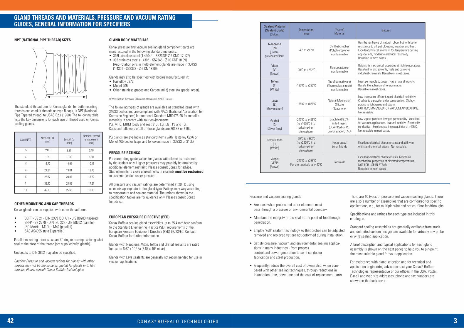
The plastic deformation of a sealant material within a fixed housing is the fundamental concept of the Conax® sealing technology. The application of this concept, with a thorough understanding of the behaviour of sealant materials, has resultedin a range of assemblies with unequalled adaptability.
When an element (probe, sensor, electrode etc.) is inserted in a glandand the cap is torqued to the recommended setting, the torque on thecap translates an axial force on the follower which compresses orcrushes the sealant that is contained within the body thus creating a seal on the element. Tension in the body acts like a spring to maintain compression; friction between the sealant and the elementrestrains the element from moving under pressure or vacuum.
The five standard sealant materials and some selected specialsealants are listed on the following page with their properties andcharacteristics.
SEALANT
FOLLOWER
BODYCAP
FOLLOWER
BODY SEALANT
THE COMPLETE SEALING GLAND CATALOGUE PROVEN PERFORMERS
AN INTRODUCTION TO PRESSURE AND VACUUM SEALING ASSEMBLIES‘SOFT’ SEALANTS AND THEIR CHARACTERISTICS
Contents
Product Directory Pages 2-5
Sealing Gland Selection Guide Pages 6-9
PG glands - for single sensors and probes Pages 10-11
MK glands - for single tubes or probes Pages 12-13
EG and EGT glands - with integral, single electodes for high voltage and current Pages 14-15
MHC glands - for multiple sensors and probes Pages 16-17
MHM glands - for non-standard sizes and custom configurations of multiple elements Pages 18-19
PL glands - for sealing insulated wire Pages 20-21
TG glands - for sealing multiple bare wires Pages 22-24
BSWS seals - Bearing sensor wire seals Page 25
PGS, SPG and DSPG glands - with split internal components for multiple elements Pages 26-27
FSA assemblies - Fibre optic seal assemblies Pages 28-29
HD assemblies - High density, insulated wire feedthrough assemblies Pages 30-31
High Pressure Sealing Assemblies Page 32
Custom sealing assemblies Pages 33-34
Accessories Page 35
Assembly instructions Pages 36-41
Conversion data - wire sizes and operating parameters Page 41
Gland threads and materials, vacuum rating Page 42
The following trademarks are used in this catalogue:Teflon is a registered trademark of E I Du Pont de NemoursViton is a registered trademark of DuPont Dow Elastomers LLCGrafoil is a registered trademark of the UCAR Carbon CompanyKapton is a registered trademark of E I Du Pont de NemoursHastelloy is a registered trademark of Hayes Intl.Monel is a registered trademark of INCOChromel-Alumel is a registered tradename of Hoskins Manufacturing
Conax® Buffalo Technologies has a policy of continuous improvement. Specifications may be subject to change without notice.
3
Pressure and vacuum sealing glands
• Are used when probes and other elements mustpass through a pressure or environmental boundary.
• Maintain the integrity of the seal at the point of feedthroughpenetration.
• Employ ‘soft’ sealant technology so that probes can be adjusted,removed and replaced yet are not deformed during installation.
• Satisfy pressure, vacuum and environmental sealing applica-tions in many industries - from process control and power generation to semi-conductor fabrication and steel production.
• Frequently reduce the overall cost of ownership, when com-pared with other sealing techniques, through reductions ininstallation time, downtime and the cost of replacement parts.
There are 10 types of pressure and vacuum sealing glands. Thereare also a number of assemblies that are configured for specificapplications, e.g., for multiple wire and optical fibre feedthroughs.
Specifications and ratings for each type are included in this catalogue.
Standard sealing assemblies are generally available from stock and unlimited custom designs are available for virtually any probeor wire sealing application.
A brief description and typical applications for each gland assembly is shown on the next pages to help you to pin-point the most suitable gland for your application.
For assistance with gland selection and for technical and application engineering advice contact your Conax® BuffaloTechnologies representative or our offices in the USA. Postal, E-mail and web site addresses, phone and fax numbers are shown on the back cover.
Sealant Material(Sealant Code)
[Colour]
Neoprene(N)
[Green - previously Black]
Viton(V)
[Brown]
Teflon(T)
[White]
Lava(L)
[Grey mixture]
Grafoil(G)
[Silver Grey]
Boron Nitride(H)
[White]
Vespel(VESP)[Brown]
Temperaturerange
-40º to +93ºC
-20ºC to +232ºC
-185ºC to +232ºC
-185ºC to +870ºC
-240ºC to +495ºC(to +1650ºC in areducing/inertatmosphere)
-20ºC to +982ºC(to +2800ºC in areducing/inertatmosphere)
-240ºC to +288ºCFor short periods to +440ºC
Type of Material
Synthetic rubber(Polychloroprene)
nonflammable
Fluoroelastomernonflammable
Tetrafluoroethylene(Thermoplastic resin)
nonflammable
Natural MagnesiumSilicate
(Soapstone)
Graphite (99.5%)in foil layers
(UCAR Carbon Co.Grafoil grade GTA-J)
Hot pressedBoron Nitride
Polyimide
Features
Has the resilience of natural rubber but with betterresistance to oil, petrol, ozone, weather and heat.Excellent physical 'memory' for temperature cyclingapplications, moderate electrical resistivity.Reusable in most cases.
Retains its mechanical properties at high temperaturesResistant to oils, solvents, fuels and corrosiveindustrial chemicals. Reusable in most cases.
Least permeable to gases. Has a natural lubricity.Resists the adhesion of foreign matter.Reusable in most cases.
Low thermal co-efficient, good electrical resistivity.Crushes to a powder under compression. Slightlyporous to light gases and steam.NOT RECOMMENDED FOR VACUUM APPLICATIONS.Not reusable.
Low vapour pressure, low gas permeability - excellentfor vacuum applications. Natural lubricity. Electricallyconductive. Excellent sealing capabilities at +495oC.Not reusable in most cases.
Excellent electrical characteristics and ability towithstand chemical attack. Not resuable.
Excellent electrical characteristics. Maintainsmechanical properties at elevated temperatures.NOT FOR USE IN STEAM.Reusable in most cases.
42 C O N A X ® B U F FA L O T E C H N O L O G I E S
GLAND THREADS AND MATERIALS, PRESSURE AND VACUUM RATINGGUIDES, GENERAL INFORMATION FOR SPECIFIERS
Size (NPT)
1⁄16
1⁄8
1⁄4
1⁄2
3⁄4
1
11⁄4
Nominal OD(mm)
7.925
10.29
13.72
21.34
26.67
33.40
42.16
Length 'x'(mm)
9.90
9.90
14.98
19.81
20.07
24.89
25.65
Nominal threadengagement
(mm)
6.10
6.60
10.16
12.70
13.72
17.27
18.03
NPT (NATIONAL PIPE THREAD) SIZES GLAND BODY MATERIALS
OTHER MOUNTING AND CAP THREADS
The standard threadform for Conax glands, for both mountingthreads and conduit threads on type B caps, is NPT (NationalPipe Tapered thread) to USAS B2.1 (1968). The following tablelists the key dimensions for each size of thread used on Conaxsealing glands.
Conax pressure and vacuum sealing gland component parts are manufactured in the following standard materials: • 316L stainless steel (1.44041) – SS23482) Z 2 CND 17.123)) • 303 stainless steel (1.4305 - SS2346 - Z 10 CNF 18.09)
(Anti-rotation pins in multi-element glands are made in 304SS(1.4301 - SS2332 - Z 6 CN 18.09)
Glands may also be specified with bodies manufactured in:• Hastelloy C276• Monel 405• Other stainless grades and Carbon (mild) steel (to special order).
1) Werkstoff Nr, (Germany) 2) Swedish Standard 3) AFNOR (Franco)
The following types of glands are available as standard items with316SS bodies and are compliant with NACE (National Association forCorrosion Engieers) International Standard MR0175-96 for metallicmaterials in contact with sour environments: PG, MHC, MHM (body and seat 316), EG, EGT, PL and TG. Caps and followers of all of these glands are 303SS or 316L.
PG glands are available as standard items with Hastelloy C276 orMonel 405 bodies (caps and followers made in 303SS or 316L).
Pressure rating guide values for glands with elements restrained by the sealant only. Higher pressures may possibly be attained byadditional element restraint. Please consult Conax for advice. Stub elements to close unused holes in sealants must be restrainedto prevent ejection under pressure.
All pressure and vacuum ratings are determined at 20° C using elements appropriate to the gland type. Ratings may vary accordingto temperature and sealant material. The ratings shown in the specification tables are for guidance only. Please consult Conax for advice.
Conax Buffalo sealing gland assemblies up to 25.4 mm bore conformto the Standard Engineering Practice (SEP) requirements of theEuropean Pressure Equipment Directive (PED) 97/23/EC. ContactConax Buffalo for further information.
Glands with Neoprene, Viton, Teflon and Grafoil sealants are ratedfor use to 6.67 x 10⁻⁴ Pa (6.67 x 10⁻⁶ mbar).
Glands with Lava sealants are generally not recommended for use invacuum applications.
Conax glands can be supplied with other threadforms:
• BSPT - BS 21 - DIN 2999 ISO 7/1 - JIS B0203 (tapered)• BSPP - BS 2779 - DIN ISO 228 - JIS B0202 (parallel)• ISO Metric - M1O to M42 (parallel)• SAE AS4395 style E (parallel)
Parallel mounting threads use an ‘O’-ring or a compression gasketseal at the base of the thread (not supplied with glands).
Undercuts to DIN 3852 may also be specified.
Caution: Pressure and vacuum ratings for glands with otherthreads may not be the same as quoted for glands with NPTthreads. Please consult Conax Buffalo Technologies.
PRESSURE RATINGS
EUROPEAN PRESSURE DIRECTIVE (PED)
X
4 C O N A X ® 5
PRODUCT DIRECTORY
Single electrode with ceramic insulators - EG glands; and with Teflon insulator/sealant - EGT glands - pages 14 & 15.
These single conductor sealing glands are used for high voltageand/or high current feedthroughs to vacuum chambers, autoclaves,transformers, motor enclosures, reactor vessels and environmentalchambers.
EG glands are available with a choice of sealants and have ceramicinsulators. Max.rating 2kV/400A.
EGT glands employ a single-piece, Teflon, combined insulator/sealant component to surround the electrode. Max.rating 8kV/525A.
Copper, Nickel or Stainless Steel electrodes may be specified.
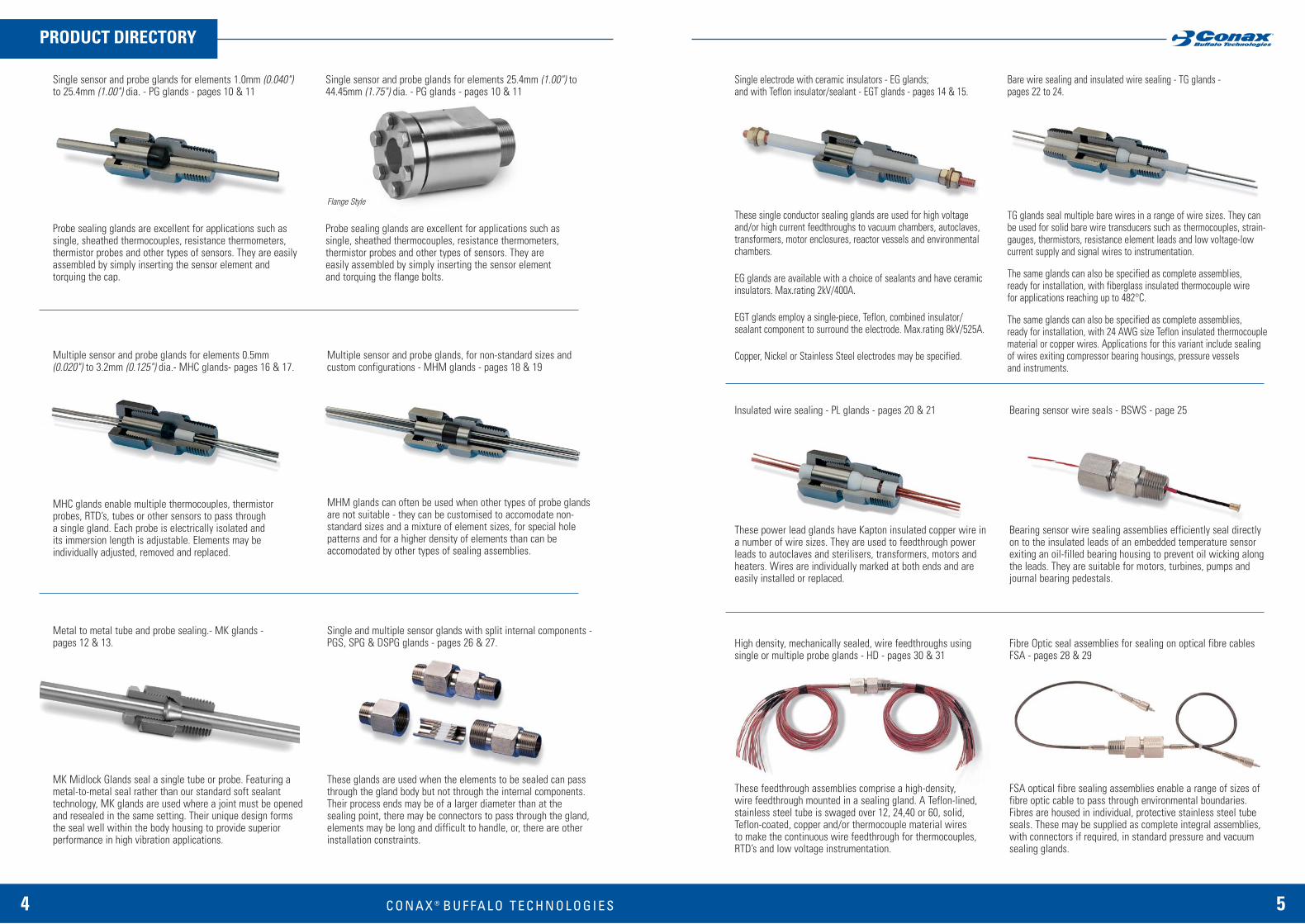
Single sensor and probe glands for elements 1.0mm (0.040")to 25.4mm (1.00") dia. - PG glands - pages 10 & 11
Probe sealing glands are excellent for applications such assingle, sheathed thermocouples, resistance thermometers,thermistor probes and other types of sensors. They are easilyassembled by simply inserting the sensor element andtorquing the cap.
Multiple sensor and probe glands, for non-standard sizes and custom configurations - MHM glands - pages 18 & 19
MHM glands can often be used when other types of probe glandsare not suitable - they can be customised to accomodate non-standard sizes and a mixture of element sizes, for special holepatterns and for a higher density of elements than can be accomodated by other types of sealing assemblies.
Multiple sensor and probe glands for elements 0.5mm(0.020") to 3.2mm (0.125") dia.- MHC glands- pages 16 & 17.
MHC glands enable multiple thermocouples, thermistorprobes, RTD’s, tubes or other sensors to pass through a single gland. Each probe is electrically isolated and its immersion length is adjustable. Elements may be individually adjusted, removed and replaced.
Metal to metal tube and probe sealing.- MK glands - pages 12 & 13.
MK Midlock Glands seal a single tube or probe. Featuring ametal-to-metal seal rather than our standard soft sealant technology, MK glands are used where a joint must be openedand resealed in the same setting. Their unique design formsthe seal well within the body housing to provide superior performance in high vibration applications.
Single and multiple sensor glands with split internal components -PGS, SPG & DSPG glands - pages 26 & 27.
These glands are used when the elements to be sealed can passthrough the gland body but not through the internal components.Their process ends may be of a larger diameter than at the sealing point, there may be connectors to pass through the gland,elements may be long and difficult to handle, or, there are otherinstallation constraints.
Single sensor and probe glands for elements 25.4mm (1.00") to44.45mm (1.75") dia. - PG glands - pages 10 & 11
Probe sealing glands are excellent for applications such as single, sheathed thermocouples, resistance thermometers,thermistor probes and other types of sensors. They are easily assembled by simply inserting the sensor element and torquing the flange bolts.
Flange Style
Bare wire sealing and insulated wire sealing - TG glands - pages 22 to 24.
TG glands seal multiple bare wires in a range of wire sizes. They canbe used for solid bare wire transducers such as thermocouples, strain-gauges, thermistors, resistance element leads and low voltage-lowcurrent supply and signal wires to instrumentation.
The same glands can also be specified as complete assemblies, ready for installation, with fiberglass insulated thermocouple wire for applications reaching up to 482°C.
The same glands can also be specified as complete assemblies, ready for installation, with 24 AWG size Teflon insulated thermocouplematerial or copper wires. Applications for this variant include sealingof wires exiting compressor bearing housings, pressure vessels and instruments.
Insulated wire sealing - PL glands - pages 20 & 21
These power lead glands have Kapton insulated copper wire ina number of wire sizes. They are used to feedthrough powerleads to autoclaves and sterilisers, transformers, motors andheaters. Wires are individually marked at both ends and areeasily installed or replaced.
Bearing sensor wire seals - BSWS - page 25
Bearing sensor wire sealing assemblies efficiently seal directlyon to the insulated leads of an embedded temperature sensorexiting an oil-filled bearing housing to prevent oil wicking alongthe leads. They are suitable for motors, turbines, pumps andjournal bearing pedestals.
High density, mechanically sealed, wire feedthroughs using single or multiple probe glands - HD - pages 30 & 31
These feedthrough assemblies comprise a high-density, wire feedthrough mounted in a sealing gland. A Teflon-lined,stainless steel tube is swaged over 12, 24,40 or 60, solid,Teflon-coated, copper and/or thermocouple material wires to make the continuous wire feedthrough for thermocouples,RTD’s and low voltage instrumentation.
Fibre Optic seal assemblies for sealing on optical fibre cablesFSA - pages 28 & 29
FSA optical fibre sealing assemblies enable a range of sizes offibre optic cable to pass through environmental boundaries.Fibres are housed in individual, protective stainless steel tubeseals. These may be supplied as complete integral assemblies,with connectors if required, in standard pressure and vacuumsealing glands.
B U F FA L O T E C H N O L O G I E S
6 C O N A X ® 7
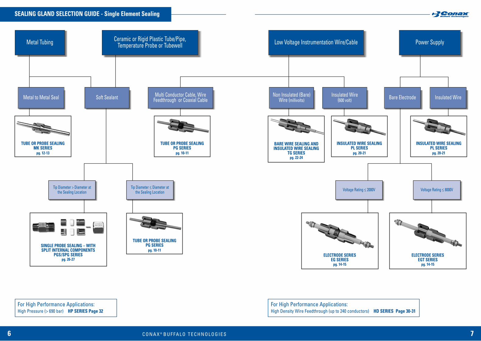
SEALING GLAND SELECTION GUIDE - Single Element Sealing
Ceramic or Rigid Plastic Tube/Pipe,Temperature Probe or TubewellMetal Tubing
Metal to Metal Seal
Tip Diameter > Diameter atthe Sealing Location
Tip Diameter <_ Diameter atthe Sealing Location
Power Supply
For High Performance Applications: High Pressure (> 690 bar) HP SERIES Page 32
For High Performance Applications: High Density Wire Feedthrough (up to 240 conductors) HD SERIES Page 30-31
Soft Sealant
TUBE OR PROBE SEALING MK SERIES
pg. 12-13
SINGLE PROBE SEALING – WITH SPLIT INTERNAL COMPONENTS
PGS/SPG SERIESpg. 26-27
TUBE OR PROBE SEALING PG SERIES
pg. 10-11
Voltage Rating <_ 2000V Voltage Rating <_ 8000V
ELECTRODE SERIESEG SERIES
pg. 14-15
Bare Electrode Insulated Wire
Low Voltage Instrumentation Wire/Cable
Non Insulated (Bare)Wire (millivolts)
Insulated Wire (600 volt)
BARE WIRE SEALING ANDINSULATED WIRE SEALING
TG SERIESpg. 22-24
INSULATED WIRE SEALING PL SERIES
pg. 20-21
TUBE OR PROBE SEALING PG SERIES
pg. 10-11
Multi Conductor Cable, WireFeedthrough or Coaxial Cable
INSULATED WIRE SEALING PL SERIES
pg. 20-21
ELECTRODE SERIESEGT SERIES
pg. 14-15
B U F FA L O T E C H N O L O G I E S

8 C O N A X ® 9
SEALING GLAND SELECTION GUIDE - Multiple Element Sealing
Elements of Different Diameter
Low Voltage InstrumentationWire/Cable
Elements of Same Diameter
Ceramic or Metallic SheathProbe/Sensor Power Supply Wire
BARE WIRE SEALING ANDINSULATED WIRE SEALING
TG SERIESpg. 22-24
INSULATED WIRE SEALING PL SERIES
pg. 20-21
INSULATED WIRE SEALING PL SERIES
pg. 20-21
INSULATED WIRE SEALING TGF SERIES
pg. 22-24
Tip Diameter > Diameter atSealing Location
Tip Diameter <_ Diameter atSealing Location
CUSTOM MULTIPLE TUBE OR PROBE SEALING
MHM SERIESpg. 18-19
CUSTOM MULTIPLE TUBE OR PROBE SEALING
MHC SERIESpg. 16-17
MULTIPLE WIRE OR PROBE SEALING
BSWS SERIESpg. 25
CUSTOM MULTIPLE TUBE OR PROBE SEALING
MHM SERIESpg. 18-19
Instrumental Lead <_ 3.5 bar Coaxial Cable or Instrument Lead > 3.5 bar
Bare Wire(T/C or CU)
MULTIPLE TUBE OR PROBE SEALING – WITH
SPLIT INTERNAL COMPONENTSSPG/DSPG SERIES
pg. 26-27
MULTIPLE TUBE OR PROBE SEALING – WITH
SPLIT INTERNAL COMPONENTSSPG/DSPG SERIES
pg. 26-27
Tip Diameter <_ Diameter atSealing Location
Tip Diameter > Diameter atSealing Location
CBT SuppliedInsulated Leadwire
INSULATED WIRE SEALING TG24T SERIES
pg. 22-24
24AWG (Solid) Teflon InsulatedT/C or Copper Wire
(Process Temp up to 232° C)
Kapton InsulatedSolid Wire
20 or 24AWG (Solid) Fiberglass Insulated T/C Wire
(Process Temp up to 482° C)
INSULATED WIRE SEALING PL SERIES
pg. 20-21
Customer SuppliedInsulated Wire
B U F FA L O T E C H N O L O G I E S

10 C O N A X ® 11
TUBE OR PROBE SEALING - PG GLANDS
• SEALS A SINGLE ELEMENT - USUALLY A TUBE, PROBE OR SENSOR
• FOR GAS OR LIQUID APPLICATIONS
• PRESSURE: Vacuum to 690 bar
• TEMPERATURE: -240°C to +870°C
• FIELD ADJUSTABLE
• REPLACEABLE SEALANT FOR REPEATED USE OF FITTING
• STAINLESS STEEL BODY, CAP AND FOLLOWER
• SIMPLE ASSEMBLY - INSERT ELEMENT, TORQUE CAP
PG glands are designed for sealing a single element, usually a tube or probe, where it crosses a pressure or environmental boundary. Glands are available to carry elements in both metric and inch sizes from micro-probes of 1.0mm (0.040”) dia. to tubesand pipes of 44.45mm (1.75”) dia.
Applications for PG glands include: Pressure and vacuum sealing of thermocouples, RTD’s, dial-typethermometers, thermistor probes, glass thermometers, thermowells(pockets) - including those made from fragile materials, capilliarytubes and other sensor elements.
PG gland parts are manufactured from Stainless Steel AISI grades316L (W.-Nr. 1.4404) and 303 (1.4305). Other materials, 316SS(NACE), Hastelloy C276, Monel 405 are available.
Installation information and torque settings for glands are shown inthe Assembly Instructions, see pages 36 to 41.
Conax pressure and vacuum sealing assemblies can be specified for use in a range of temperature, pressure and environmental situations by choosing a sealant that is suitable for the application.Replacement sealants are available to enable repeated use of fittings.
Note 1:The Gland Description [Order Code] shown in the table is completed by selecting the type of cap required - A or B is inserted at *. (MIC, PG8, and PG9 - type B not available). The code letter for the sealant selected isinserted at **(See opposite page for sealant information)
Example: PG2-118-A-Ndescribes a PG2 size gland (1⁄4" NPTmounting thread) suitable for a 3.0mm dia.element, with type A cap and Neoprene sealant.
Replacement Sealant Order CodeExample: RS-PG2-118-N
Note 2:Tolerance of tube or probe diameter ±0.127mm (0.005”). Deviation from the nominal may affect pressure ratings.
Note 3:All pressure and vacuum ratings are determined at 20°C with a stainless steel rod as the element.
Note 4:PG5 glands are available with a 3⁄4" NPT or a 1" NPT mounting thread. The gland descriptionPG5- etc. indicates that a 3⁄4" NPT mounting is required; the description PG5(1"NPT)- etc. indicates that a 1" NPT mounting thread isrequired.
Note 5:Where no value is shown in the tables theoption is not available.
Note 6:Pressure ratings on large bore models may be influenced by numerous factors and aretherefore application specific. Please consultConax® Buffalo Technologies for details.
Note 7:PG7, PG8, PG9 gland assemblies have a flange-design cap with qty. 6 x hex. head cap screws.
SEALANT
SPECIFICATIONS, ORDERING INFORMATION NOTES
Glands with type ‘B’ cap have athreaded extension on the capfor a conduit connection. Thethread is the same size as thegland mounting thread.
Viton(V)
-
110
-
193
85
85
690
85
690
100
310
205
100
110
100
100
80
35
60
60
55
55
69
69
69
69
69
69
69
Gland Description[Order Code]
(See notes 1 & 4)
MIC - 040 - A - * *
MPG - 040 - A - * *
MIC - 062 - A - * *
MPG - 062 - * - * *
MPG - 093 - * - * *
MPG - 118 - * - * *
PG2 - 118 - * - * *
MPG - 125 - * - * *
PG2 - 125 - * - * *
MPG - 187 - * - * *
PG2 - 187 - * - * *
PG2 - 236 - * - * *
PG4 - 236 - * - * *
PG2 - 250 - * - * *
PG4 - 250 - * - * *
PG5 - 250 - * - * *
PG4 - 312 - * - * *
PG4 - 375 - * - * *
PG5 - 375 - * - * *
PG5 - 500 - * - * *
PG5 - 625 - * - * *
PG5 - 750 - * - * *
PG6 - 840 - * - * *
PG7 - 840 - * - * *
PG6 - 875 - * - * *
PG6 - 1000 - * - * *
PG7 - 1000 - A - * *
PG7 - 1050 - A - * *
PG7 - 1250 - A - * *
PG8 - 1250
PG8 - 1500
PG9 - 1500
PG9 - 1750
Diameter ofelement
to be sealed(See note 2)
mm in.
1.0 0.040
1.5 0.062
0.093
3.0
0.125
0.187
6.0
0.25
8.0 0.312
0.375
0.5
0.625
0.75
21.34 1⁄2" pipe
21.34 1⁄2" pipe
0.875
1.0
1.05
31.75 1.25
31.75 1.25
38.1 1.50
44.45 1.75
Glandmounting
thread(NPT)
(See note 4)
1 ⁄16"
1 ⁄8"
1 ⁄16"
1 ⁄8"
1 ⁄8"
1 ⁄8"
1 ⁄4"
1 ⁄8"
1 ⁄4"
1 ⁄8"
1 ⁄4"
1 ⁄4"
1 ⁄2"
1 ⁄4"
1 ⁄2"
3 ⁄4" or 1"
1 ⁄2"
1 ⁄2"
3 ⁄4" or 1"
3⁄4" or 1"
3⁄4" or 1"
3⁄4" or 1"
1"
1 1 ⁄4"
1"
1
1 1 ⁄4"
1 1 ⁄4"
1 1 ⁄4"
1 1 ⁄2"
1 1 ⁄2"
2"
2"
Neoprene(N)
-
138
-
110
85
85
345
85
345
85
220
165
100
110
100
100
80
80
60
60
55
55
-
-
-
-
-
-
-
-
-
-
-
Pressure rating by sealant (bar)(See notes 3, 5 & 6)
Grafoil(G)
-
110
-
140
165
165
690
165
690
55
345
275
345
275
345
345
345
220
165
165
165
165
-
51
-
-
51
51
51
Lava(L)
550
193
550
220
140
140
690
140
690
140
690
690
690
635
690
690
690
690
345
345
275
275
-
34
-
-
34
34
34
Teflon(T)
220
110
220
110
55
55
220
55
220
100
165
80
165
30
165
165
135
95
100
100
55
55
27.5
-
27.5
27.5
-
-
-
Size of gland
MIC
MPG
PG2
PG4
PG5
PG6
PG7
PG8
PG9
Glandmounting
thread(NPT)
1⁄16"1⁄8"1⁄4"1⁄2"
3⁄4" & 1"
1"
11⁄4"
11⁄2"
2"
BodyHex size
(in.)
11⁄32
1⁄23⁄4
111⁄4
13⁄4
CapHex size
(in.)
11⁄32
1⁄23⁄4
111⁄4
2
Length ofgland withtype A cap
Dim. A (mm)
23.81
30.16
50.80
63.50
73.03
88.90
95.25
108.00
128.58
Length ofgland withtype B cap
Dim. B (mm)
-
39.69
60.33
82.55
92.08
114.30
127.00
-
-
76.20mm dia.
101.60mm dia.
127.00mm dia.
DIMENSIONS
See Note 6
SEALANT SELECTION GUIDE
Sealant(Sealant Code)
Neoprene (N)
Viton (V)
Teflon (T)
Lava (L)
Grafoil (G)
Temperature range
-40ºC to +93ºC
-20ºC to +232ºC
-185ºC to +232ºC
-185ºC to + 870ºC
-240ºC to +495ºC (to +1650ºC in a reducing atmos.)
Pressure range@ 20ºC
Vacuum to 345 bar
Vacuum to 690 bar
Vacuum to 220 bar
1bar to 690 bar
Vacuum to 690 bar
All glands exceptPG7, PG8, PG9
PG7, PG8, PG9(See Note 7)
Capside
Processside
Processside
A
A
B
B U F FA L O T E C H N O L O G I E S
12 C O N A X ® 13
TUBE OR PROBE SEALING - MK GLANDSSPECIFICATIONS, ORDERING INFORMATION NOTES
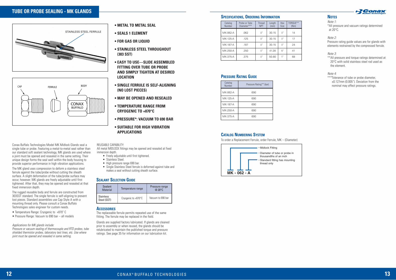
MK - 062 - A
• Midlock Fitting
• Diameter of tube or probe inthousandths of an inch
• Standard fitting has mountingthread only
• METAL TO METAL SEAL
• SEALS 1 ELEMENT
• FOR GAS OR LIQUID
• STAINLESS STEEL THROUGHOUT(303 SST)
• EASY TO USE—SLIDE ASSEMBLEDFITTING OVER TUBE OR PROBE AND SIMPLY TIGHTEN AT DESIREDLOCATION
• SINGLE FERRULE IS SELF-ALIGNING(NO LOST PIECES)
• MAY BE OPENED AND RESEALED
• TEMPERATURE RANGE FROMCRYOGENIC TO +870°C
• PRESSURE*: VACUUM TO 690 BAR
• SUITABLE FOR HIGH VIBRATIONAPPLICATIONS
Conax Buffalo Technologies Model MK Midlock Glands seal asingle tube or probe. Featuring a metal-to-metal seal rather thanour standard soft sealant technology, MK glands are used wherea joint must be opened and resealed in the same setting. Theirunique design forms the seal well within the body housing toprovide superior performance in high vibration applications. The MK gland uses compression to deform a stainless steelferrule against the tube/probe without cutting the sheathsurface. A slight deformation of the tube/probe surface mayoccur, however. MK glands are freely adjustable until firsttightened. After that, they may be opened and resealed at thatfixed immersion depth. The rugged reusable body and ferrule are constructed from303SST standard. The single ferrule is self-aligning to preventlost pieces. Standard assemblies use Cap Style A with amounting thread only. Please consult a Conax BuffaloTechnologies sales engineer for custom needs.• Temperature Range: Cryogenic to +870˚ C• Pressure Range: Vacuum to 690 bar – all models
Applications for MK glands include: Pressure or vacuum sealing of thermocouple and RTD probes, tubeshielded thermistor probes, laboratory test lines, etc. Use wherejoint must be opened and resealed in same setting.
REUSABLE CAPABILITY:All metal MIDLOCK fittings may be opened and resealed at fixedimmersion depth.
• Freely adjustable until first tightened.• Stainless Steel. • High pressure range 690 bar.• Single Stainless Steel ferrule is deformed against tube and
makes a seal without cutting sheath surface.
Note 1:*All pressure and vacuum ratings determined at 20°C.
Note 2:Pressure rating guide values are for glands withelements restrained by the compressed ferrule.
Note 3:**All pressure and torque ratings determined at
20°C with solid stainless steel rod used asthe element.
Note 4:***Tolerance of tube or probe diameter,
±0.127mm (0.005”). Deviation from the nominal may effect pressure ratings.
STAINLESS STEEL FERRULE
SEALANT SELECTION GUIDE
SealantMaterial
StainlessSteel (SST)
Temperature range
Cryogenic to +870°C
Pressure range@ 20°C
Vacuum to 690 bar
Catalog Probe or Tube Thread Length Hex TORQUE**Number Diameter*** NPT (mm) Size (Nm)
MK-062-A .062 1⁄8" 30.15 1⁄2" 14
MK-125-A .125 1⁄8" 30.15 1⁄2" 17
MK-187-A .187 1⁄8" 30.15 1⁄2" 24
MK-250-A .250 1⁄4" 41.28 5⁄8" 41
MK-375-A .375 1⁄2" 50.80 1" 68
PRESSURE RATING GUIDE
CATALOG NUMBERING SYSTEM
CatalogPressure Rating** (bar)Number
MK-062-A 690
MK-125-A 690
MK-187-A 690
MK-250-A 690
MK-375-A 690
ACCESSORIESThe replaceable ferrule permits repeated use of the samefitting. The ferrule may be replaced in the field.
Glands are supplied factory lubricated. If glands are cleanedprior to assembly or when reused, the glands should berelubricated to maintain the published torque and pressureratings. See page 35 for information on our lubrication kit.
To order a Replacement Ferrule, order Ferrule, MK – (Diameter)
B U F FA L O T E C H N O L O G I E S
1514 C O N A X ® B U F FA L O T E C H N O L O G I E S
ELECTRODE SEALING – EG & EGT GLANDSSPECIFICATIONS, ORDERING INFORMATION NOTES
Note 1:The Gland Description [Order Code] shown in thetable, is completed by selecting the type of caprequired - A or B is inserted at *. The code for the electrode required is inserted as follows: CU for Copper (Max. temp. 380°C).NI for Nickel (Max. temp. 600°C). SS for Stainless Steel (Max. temp. 870°C)XX without an electrode For EG glands the code letter for the sealantselected is inserted at **. (See opposite for sealant information).
EG example: EG-125-B-NI-Ldescribes an EG-125 size gland (1⁄4" NPTmounting thread) with a nickel electrode rated15A max., with type B cap and Lava sealant.
EGT example: EGT-250-A-CU describes an EGT-250 size gland ( 1⁄2" NPT mount-ing thread) with a copper electrode rated 95Amax., and type A cap.
Replacement Sealant Order CodeExamples: RS-EG-125-L
RS-EGT-250
Replacement Packing Set Order Code for EGglands (Sealant and two ceramic insulators)Example: RPS-EG-125-L
Replacement Insulator Order Code for EGglands (Single insulator)Example: RI-EG-125
Replacement Electrode Order CodeExamples: RE-EG-125-NI
RE-EGT-250-CU
Note 2:Electrodes have tapped threads and are fittedwith two nuts and washers at each end for ringtongue or lug-type cable terminals.
Electrodes may be substituted with tubes, probesor sensors of equivalent diameter ±0.127mm(0.005”) Caution: May affect pressure ratings.
Note 3:All pressure and vacuum ratings are determined at 20°C with a stainless steel rod asthe element. For vacuum ratings see page 42.
Note 4:Where no value is shown in the tables the optionis not available.
Note 5:EG-750 & EGT-1000 gland assemblies have a flange-design cap with qty. 6 x hex. head cap screws. EG-750 Flange dia. 82.55mm.Type B cap not available. An EG-750 gland and anEGT-1000 body style is same as PG-7 on page 10.
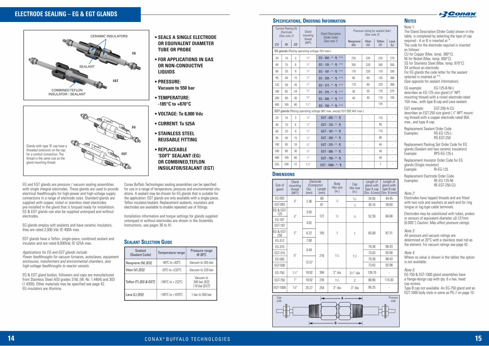
• SEALS A SINGLE ELECTRODEOR EQUIVALENT DIAMETERTUBE OR PROBE
• FOR APPLICATIONS IN GASOR NON-CONDUCTIVE LIQUIDS
• PRESSURE: Vacuum to 550 bar
• TEMPERATURE:-185°C to +870°C
• VOLTAGE: To 8,000 Vdc
• CURRENT: To 525A
• STAINLESS STEELREUSABLE FITTING
• REPLACEABLE ‘SOFT’ SEALANT (EG) OR COMBINED,TEFLONINSULATOR/SEALANT (EGT)
EG and EGT glands are pressure / vacuum sealing assemblieswith single integral electrodes. These glands are used to provideelectrical feedthroughs for high-power and high-voltage supplyconnections in a range of electrode sizes. Standard glands aresupplied with copper, nickel or stainless steel electrodes pre-installed in the gland that is torqued ready for installation.EG & EGT glands can also be supplied untorqued and withoutelectrodes.
EG glands employ soft sealants and have ceramic insulators,they are rated 2,000 Vdc © 400A max.
EGT glands have a Teflon, single-piece, combined sealant andinsulator and are rated 8,000Vdc © 525A max..
Applications for EG and EGT glands include: Power feedthroughs for vacuum furnaces, autoclaves, equipmentenclosures, transformers and environmental chambers, also high-voltage feedthroughs to reactor vessels.
EG & EGT gland bodies, followers and caps are manufacturedfrom Stainless Steel AISI grades 316L (W.-Nr. 1.4404) and 303(1.4305). Other materials may be specified see page 42. EG insulators are Alumina.
Conax Buffalo Technologies sealing assemblies can be specifiedfor use in a range of temperature, pressure and environmental situ-ations. A sealant may be chosen for EG glands that is suitable forthe application. EGT glands are only available with a single-piece,Teflon insulator/sealant. Replacement sealants, insulators andelectrodes are available to enable repeated use of fittings.
Installation information and torque settings for glands supplieduntorqued or without electrodes are shown in the AssemblyInstructions, see pages 36 to 41.
DIMENSIONS
Glands with type ‘B’ cap have athreaded extension on the capfor a conduit connection. Thethread is the same size as thegland mounting thread.
Sealant(Sealant Code)
Neoprene (N) [EG]
Viton (V) [EG]
Teflon (T) [EG & EGT]
Lava (L) [EG]
Temperature range
-40ºC to +93ºC
-20ºC to +232ºC
-185ºC to + 232ºC
-185ºC to + 870ºC
Pressure range@ 20ºC
Vacuum to 355 bar
Vacuum to 220 bar
Vacuum to345 bar [EG]170 bar [EGT]
1 bar to 550 bar
SEALANT SELECTION GUIDE
Neoprene(N)
220
355
170
80
110
40
40
-
-
-
-
-
-
-
-
-
Viton(V)
220
220
220
80
80
55
40
-
-
-
-
-
-
-
-
-
Teflon(T)
220
345
170
135
220
170
110
125
170
80
110
80
40
40
40
7
Lava(L)
275
550
330
380
380
275
105
-
-
-
-
-
-
-
-
-
CU
20
40
60
95
125
160
200
400
20
40
60
95
160
200
400
525
Ni
10
15
25
40
50
65
80
165
10
15
25
40
65
80
165
240
SS
3
6
9
15
20
24
30
60
3
6
9
15
24
30
60
72
Gland mounting
thread (NPT)
1⁄8"
1 ⁄4"
1 ⁄4"
1 ⁄2"
1 ⁄2"
3 ⁄4"
3 ⁄4"
11⁄2"
1 ⁄8"
1 ⁄4"
1 ⁄2"
1 ⁄2"
3 ⁄4"
3 ⁄4"
1"
11⁄4"
Pressure rating by sealant (bar)(See note 3)
Current Rating (A)Electrode
(See note 2)
EG glands (Rating operating voltage 2kV max.)
EGT glands (Rating operating voltage 8kV max. except EGT-093 4kV max.)
Size ofgland
EG-093
EGT-093
EG & EGT-125
EG-187
EGT-187
EG & EGT-250
EG-312
EG-375
EGT-375
EG-500
EGT-500
EG-750
EGT-750
EGT-1000
Glandmounting
thread(NPT)
1⁄8"
1⁄4"
1⁄2"
3⁄4"
11⁄2"
1"
11⁄4"
Dia.(mm)
2.36
3.05
4.62
6.22
7.80
9.40
12.57
18.92
18.92
25.27
Length(mm)
89
81
127
165
216
394
235
254
BodyHex size
(in.)
1 ⁄2
3 ⁄4
1
11⁄4
3” dia
13⁄4
3” dia
CapHex size
(in.)
9 ⁄16
1 ⁄2
3 ⁄4
1
11⁄2
31⁄2” dia
2
3” dia
Length ofgland withtype A cap
Dim. A (mm)
34.93
30.16
52.39
65.09
79.38
73.03
79.38
73.03
139.70
88.90
95.25
Length ofgland withtype B cap
Dim. B (mm)
44.45
39.69
66.68
87.31
98.43
92.08
98.43
92.08
-
114.30
-
Gland Description[Order Code](See note 1)
EG - 093 - * - ¶ - * *
EG - 125 - * - ¶ - * *
EG - 187 - * - ¶ - * *
EG - 250 - * - ¶ - * *
EG - 312 - * - ¶ - * *
EG - 375 - * - ¶ - * *
EG - 500 - * - ¶ - * *
EG - 750 - * - ¶ - * *
EGT - 093 - * - 
EGT - 125 - * - 
EGT - 187 - * - 
EGT - 250 - * - 
EGT - 375 - * - 
EGT - 500 - * - 
EGT - 750 - * - 
EGT - 1000 - * - 
Electrode(Conductor)
CERAMIC INSULATORS
EG
EGT
SEALANT
COMBINED TEFLONINSULATOR / SEALANT
EGT
EG
Capside
Processside
A
B
16 C O N A X ® 17
MULTIPLE TUBE OR PROBE SEALING - MHC GLANDSSPECIFICATIONS, ORDERING INFORMATION NOTES
Note 1:The Gland Description [Order Code] shown in the table, is completed by selecting thetype of cap required - A or B is inserted at *followed by the number of elements to besealed. (Where there is no choice for thenumber of elements the number is alreadyshown). The code letter for the sealantselected is inserted at **(See opposite page for sealant information).
Example: MHC4-040-B6-Tdescribes an MHC4 size gland (1⁄2”, NPTmounting thread) suitable for quantity6 x 1.0mm (0.040") dia. elements, with type B cap and Teflon sealant.
Replacement Sealant Order CodeExample: RS-MHC4-040-6-T
Replacement Packing Set Order CodeExample: RPS-MHC4-040-6-T
Note 2:Tolerance of tube or probe diameter= ±0.076mm (0.003”) for elements <1.0mm(0.040”) and ±0.127mm (0.005”) for elements >1.0mm. Deviation from the nominal may affect pres-sure ratings.
Note 3:All pressure and vacuum ratings are determined at 20°C with a stainless steel rod as the element. For vacuum ratings see page 42.
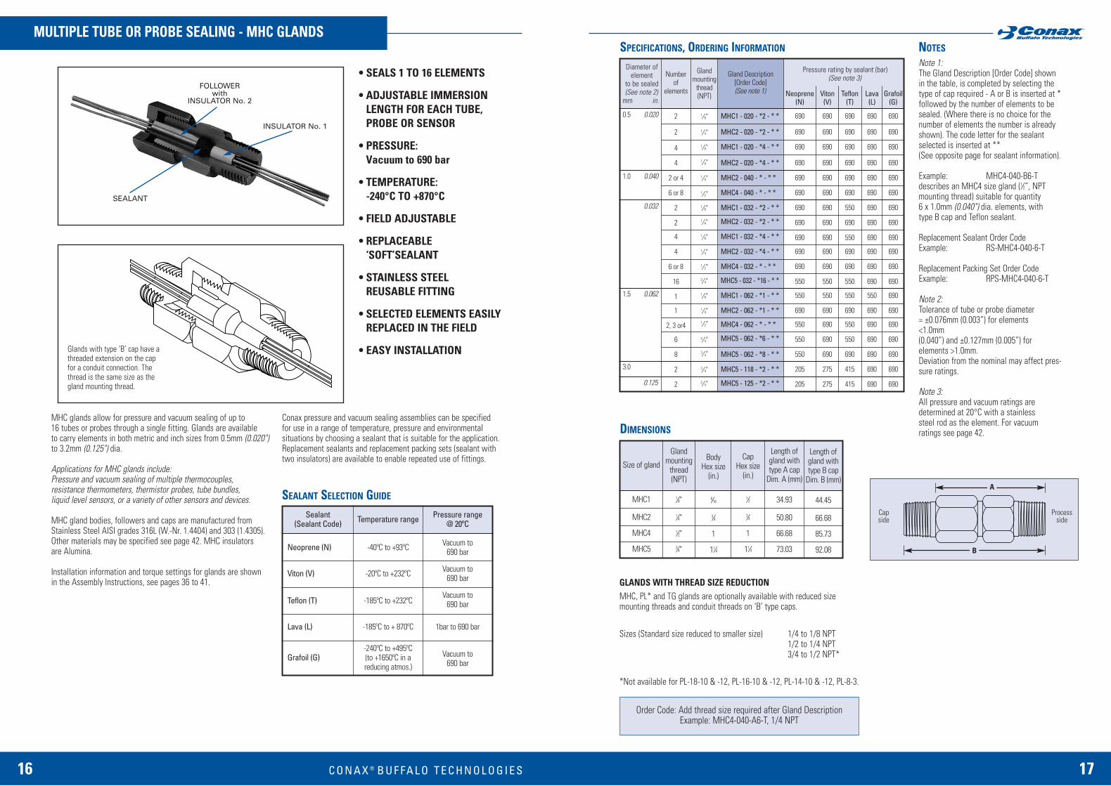
• SEALS 1 TO 16 ELEMENTS
• ADJUSTABLE IMMERSIONLENGTH FOR EACH TUBE,PROBE OR SENSOR
• PRESSURE:Vacuum to 690 bar
• TEMPERATURE:-240°C TO +870°C
• FIELD ADJUSTABLE
• REPLACEABLE ‘SOFT’SEALANT
• STAINLESS STEELREUSABLE FITTING
• SELECTED ELEMENTS EASILYREPLACED IN THE FIELD
• EASY INSTALLATION
MHC glands allow for pressure and vacuum sealing of up to 16 tubes or probes through a single fitting. Glands are available to carry elements in both metric and inch sizes from 0.5mm (0.020")to 3.2mm (0.125") dia.
Applications for MHC glands include: Pressure and vacuum sealing of multiple thermocouples, resistance thermometers, thermistor probes, tube bundles, liquid level sensors, or a variety of other sensors and devices.
MHC gland bodies, followers and caps are manufactured fromStainless Steel AISI grades 316L (W.-Nr. 1.4404) and 303 (1.4305).Other materials may be specified see page 42. MHC insulators are Alumina.
Installation information and torque settings for glands are shown in the Assembly Instructions, see pages 36 to 41.
Conax pressure and vacuum sealing assemblies can be specifiedfor use in a range of temperature, pressure and environmental situations by choosing a sealant that is suitable for the application.Replacement sealants and replacement packing sets (sealant withtwo insulators) are available to enable repeated use of fittings.
DIMENSIONS
Glands with type ‘B’ cap have athreaded extension on the capfor a conduit connection. Thethread is the same size as thegland mounting thread.
Sealant(Sealant Code)
Neoprene (N)
Viton (V)
Teflon (T)
Lava (L)
Grafoil (G)
Temperature range
-40ºC to +93ºC
-20ºC to +232ºC
-185ºC to +232ºC
-185ºC to + 870ºC
-240ºC to +495ºC(to +1650ºC in a reducing atmos.)
Pressure range@ 20ºC
Vacuum to690 bar
Vacuum to690 bar
Vacuum to690 bar
1bar to 690 bar
Vacuum to690 bar
SEALANT SELECTION GUIDE
Size of gland
MHC1
MHC2
MHC4
MHC5
Glandmounting
thread(NPT)
1⁄8"
1⁄4"
1⁄2"
3⁄4"
BodyHex size
(in.)
9⁄16
3⁄4
1
11⁄4
CapHex size
(in.)
1⁄2
3⁄4
1
11⁄4
Length ofgland withtype A cap
Dim. A (mm)
34.93
50.80
66.68
73.03
Length ofgland withtype B cap
Dim. B (mm)
44.45
66.68
85.73
92.08
Viton(V)
690
690
690
690
690
690
690
690
690
690
690
550
550
690
690
690
690
275
275
Pressure rating by sealant (bar)(See note 3)
Neoprene(N)
690
690
690
690
690
690
690
690
690
690
690
550
550
690
550
550
550
205
205
Teflon(T)
690
690
690
690
690
690
550
690
550
690
690
550
550
690
550
550
690
415
415
Lava(L)
690
690
690
690
690
690
690
690
690
690
690
690
550
690
690
690
690
690
690
Glandmounting
thread(NPT)
1⁄8"
1 ⁄4"
1 ⁄8"
1 ⁄4"
1 ⁄4"
1 ⁄2"
1 ⁄8"
1 ⁄4"
1 ⁄8"
1 ⁄4"
1 ⁄2"
3 ⁄4"
1 ⁄8"
1 ⁄4"1 ⁄2"
3 ⁄4"
3 ⁄4"
3 ⁄4"
3 ⁄4"
Diameter ofelement
to be sealed(See note 2)
mm in.
0.5 0.020
1.0 0.040
0.032
1.5 0.062
3.0
0.125
Grafoil(G)
690
690
690
690
690
690
690
690
690
690
690
690
690
690
690
690
690
690
690
Numberof
elements
2
2
4
4
2 or 4
6 or 8
2
2
4
4
6 or 8
16
1
1
2, 3 or4
6
8
2
2
Gland Description[Order Code](See note 1)
MHC1 - 020 - *2 - * *
MHC2 - 020 - *2 - * *
MHC1 - 020 - *4 - * *
MHC2 - 020 - *4 - * *
MHC2 - 040 - * - * *
MHC4 - 040 - * - * *
MHC1 - 032 - *2 - * *
MHC2 - 032 - *2 - * *
MHC1 - 032 - *4 - * *
MHC2 - 032 - *4 - * *
MHC4 - 032 - * - * *
MHC5 - 032 - *16 - * *
MHC1 - 062 - *1 - * *
MHC2 - 062 - *1 - * *
MHC4 - 062 - * - * *
MHC5 - 062 - *6 - * *
MHC5 - 062 - *8 - * *
MHC5 - 118 - *2 - * *
MHC5 - 125 - *2 - * *
GLANDS WITH THREAD SIZE REDUCTIONMHC, PL* and TG glands are optionally available with reduced size mounting threads and conduit threads on ‘B’ type caps.
Sizes (Standard size reduced to smaller size) 1/4 to 1/8 NPT1/2 to 1/4 NPT3/4 to 1/2 NPT*
*Not available for PL-18-10 & -12, PL-16-10 & -12, PL-14-10 & -12, PL-8-3.
Order Code: Add thread size required after Gland DescriptionExample: MHC4-040-A6-T, 1/4 NPT
Capside
Processside
A
B
FOLLOWERwith
INSULATOR No. 2
INSULATOR No. 1
SEALANT
B U F FA L O T E C H N O L O G I E S

18 C O N A X ® 19
• SEALS 1 TO 27 ELEMENTS(STANDARD)
• ADJUSTABLE IMMERSION LENGTH FOR EACH TUBE, PROBE OR SENSOR
• PRESSURE: Vacuum to 690 bar
• TEMPERATURE: -240°C to +870°C
• FIELD ADJUSTABLE
• REPLACEABLE ‘SOFT’ SEALANT
• STAINLESS STEELREUSABLE FITTING
• SELECTED ELEMENTS EASILY REPLACED IN THE FIELD
• EASY INSTALLATION
Glands with type ‘B’ cap have athreaded extension on the capfor a conduit connection. Thethread is the same size as thegland mounting thread.
MHM glands allow for pressure and vacuum sealing of tubes orprobes through a single fitting. They are intended for use whenother types of gland are not suitable or not available in a particularconfiguration. MHM glands may also be specified when a mixtureof element sizes need to pass through a single fitting, when specialhole patterns or irregular shapes are required and when a higherdensity of elements, than possible in other types of glands, is needed, Glands are available to carry elements in both metric and inch sizes from 1.0mm (0.040”) to 9.53mm (0.375”) dia.
Applications for MHM glands include: Pressure and vacuum sealingof gradient thermocouples, thermistor probes, tube bundles, liquidlevel sensors, or a variety of other sensors and devices in a singlefitting.
MHM gland bodies, followers, caps and seats are manufacturedfrom Stainless Steel AISI grades 316L (W.-Nr. 1.4404) and 303(1.4305). Other materials may be specified see page 42.
Installation information and torque settings for glands are shown inthe Assembly Instructions, see pages 36 to 41.
Conax pressure and vacuum sealing assemblies can be specified for use in a range of temperature, pressure and environmental situations by choosing a sealant that is suitable for the application.Replacement sealants and replacement packing sets (sealant withfollower and seat) are available to enable repeated use of fittings.
CUSTOM MULTIPLE TUBE OR PROBE SEALING - MHM GLANDSSPECIFICATIONS, ORDERING INFORMATION NOTES
The table is primarily for guidance when specifying MHM glands. Each size of gland listed shows the maximum number of each size of elements that can be accommodated at thepressure ratings indicated. The table only refers to glands which will carry a single element or multiple elements of the same diameter
Note 1:Where MHM glands are to be specified when all elements to pass through the gland are of thesame diameter, the Gland Description [Order Code]shown in the table, is completed by selecting the type of cap required - A or B is inserted at * followed by the number of elements to be sealed. The code letter for the sealant selected is inserted at **. (See opposite page for sealant information).
Example: MHM4-118-A4-Ldescribes an MHM4 size gland (1⁄2" NPTmounting thread) suitable for quantity4 x 3.0mm dia. elements, with type A cap and Lava sealant.
Replacement Sealant Order CodeExample: RS-MHM4-118-4-L
Replacement Packing Set Order CodeExample: RPS-MHM4-118-4-L
Note 2:Tolerance of tube or probe diameter = ±0.127mm (0.005"). Deviation from the nominal may affect pressure ratings.
Note 3:All pressure and vacuum ratings are determined at 20°C with a stainless steel rod as the element.For vacuum ratings see page 42.
Note 4:MHM6 gland assemblies have a flange-design capwith qty. 6 x hex. head cap screws.
Custom hole patterns can be provided for specific applications. Pressure ratings ofglands using similar patterns will be dependent on the number and size of elementsas well as the sealant material chosen.
Sealant(Sealant Code)
Neoprene (N)
Viton (V)
Teflon (T)
Lava (L)
Grafoil (G)
Temperature range
-40ºC to +93ºC
-20ºC to +232ºC
-185ºC to +232ºC
-185ºC to + 870ºC
-240ºC to +495ºC(to +1650ºC in a reducing atmos.)
Pressure range@ 20ºC
Vacuum to550 bar
Vacuum to690 bar
Vacuum to550 bar
1bar to 690 bar
Vacuum to690 bar
SEALANT SELECTION GUIDE
Viton(V)
690
470
470
470
690
495
690
495
345
310
345
310
470
345
345
690
690
414
414
207
207
Diameter ofelement
to be sealed(See note 2)
mm in.
1.0 0.040
1.5
0.062
3.0
0.125
0.187
6.0
0.250
3.0
6.0
0.375
MaximumNumber
ofelements
5
10
12
16
5
16
5
16
4
8
4
8
6
4
4
10
27
5
7
2
4
Pressure rating by sealant (bar)(See note 3)
Neoprene(N)
-
360
360
360
275
220
275
220
550
275
550
275
80
295
295
-
-
-
-
-
-
Glandmounting
thread(NPT)
1⁄4"
3 ⁄4"
3 ⁄4"
3 ⁄4"
1 ⁄4"3 ⁄4"
1 ⁄4"
3 ⁄4"1 ⁄2"
3 ⁄4"
1 ⁄2"3 ⁄4"
3 ⁄4"3 ⁄4"3 ⁄4"
1"
1"
1"
1"
1"1"
Gland Description[Order Code](See note 1)
MHM2 - 040 - * - * *
MHM5 - 040 - * - * *
MHM5 - 040 - * - * *
MHM5 - 040 - * - * *
MHM2 - 059 - * - * *
MHM5 - 059 - * - * *
MHM2 - 062 - * - * *
MHM5 - 062 - * - * *
MHM4 - 118 - * - * *
MHM5 - 118 - * - * *
MHM4 - 125 - * - * *
MHM5 - 125 - * - * *
MHM5 - 187 - * - * *
MHM5 - 236 - * - * *
MHM5 - 250 - * - * *
MHM6 - 118 - * - * *
MHM6 - 118 - * - * *
MHM6 - 236 - * - * *
MHM6 - 236 - * - * *
MHM6 - 375 - * - * *
MHM6 - 375 - * - * *
Lava(L)
690
135
170
205
690
480
690
480
690
410
690
410
580
460
460
-
-
-
-
-
-
Grafoil(G)
550
275
310
310
440
445
440
445
690
310
690
310
550
310
310
165
165
69
69
69
69
Size of gland
MHM2
MHM4
MHM5
MHM6
Glandmounting
thread(NPT)
1⁄4"
1⁄2"
3⁄4"
1"
BodyHex size
(in.)
3⁄4
1
11⁄2
DIMENSIONS
CapHex size
(in.)
3⁄4
1
11⁄2
Length ofgland withtype A cap
Dim. A (mm)
50.80
65.09
84.14
95.25
Length ofgland withtype B cap
Dim. B (mm)
66.68
85.73
106.36
127.00
Teflon(T)
220
310
310
310
165
410
165
410
550
310
550
310
110
110
110
103
103
69
69
69
69
Round Body and Cap 69.85mm dia.
MHM6 only
Capside
Processside
Processside
A
B
SEALANT
FOLLOWER
SEAT
B U F FA L O T E C H N O L O G I E S
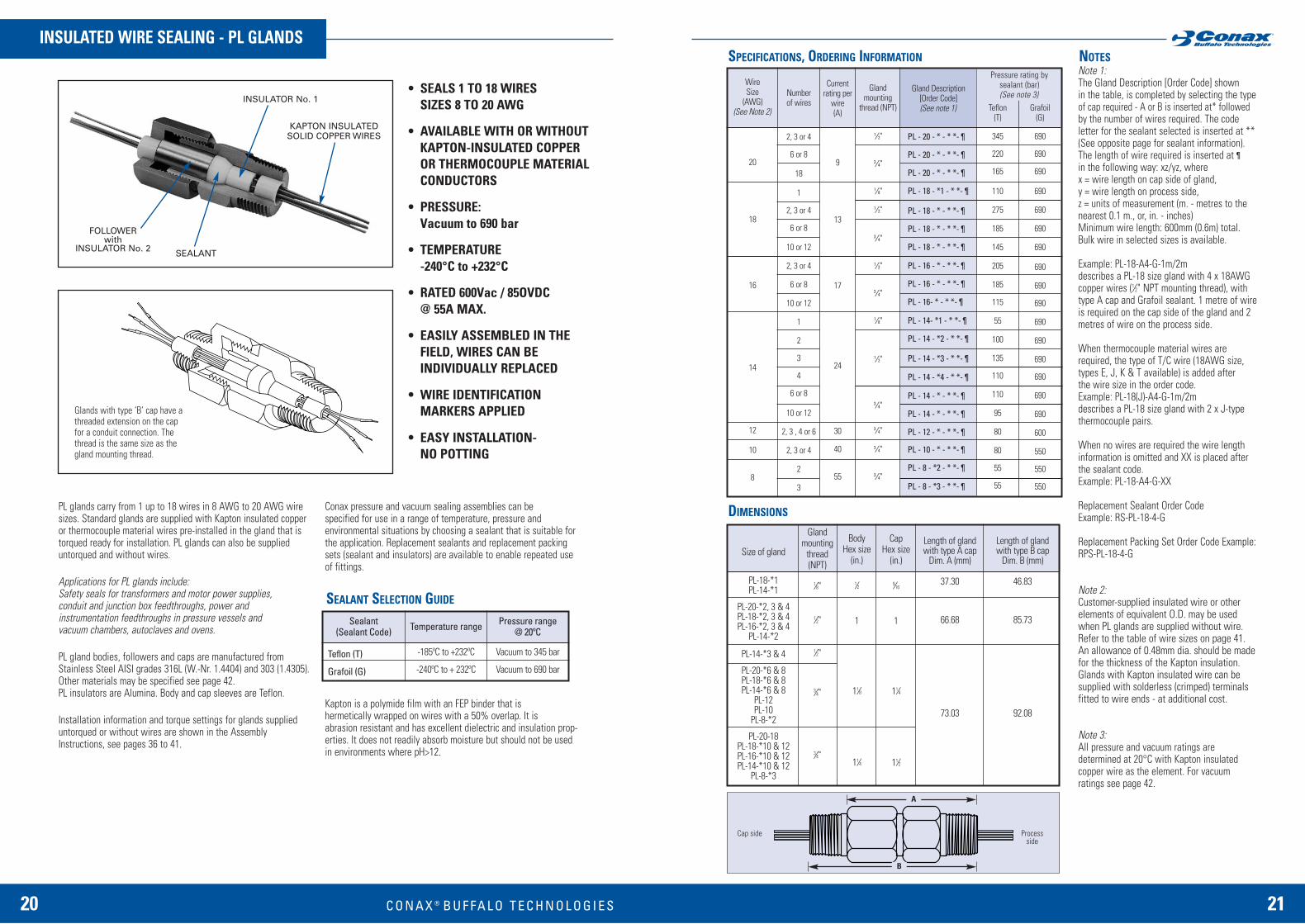
PL glands carry from 1 up to 18 wires in 8 AWG to 20 AWG wiresizes. Standard glands are supplied with Kapton insulated copperor thermocouple material wires pre-installed in the gland that istorqued ready for installation. PL glands can also be supplieduntorqued and without wires.
Applications for PL glands include: Safety seals for transformers and motor power supplies, conduit and junction box feedthroughs, power and instrumentation feedthroughs in pressure vessels and vacuum chambers, autoclaves and ovens.
PL gland bodies, followers and caps are manufactured fromStainless Steel AISI grades 316L (W.-Nr. 1.4404) and 303 (1.4305).Other materials may be specified see page 42. PL insulators are Alumina. Body and cap sleeves are Teflon.
Installation information and torque settings for glands supplieduntorqued or without wires are shown in the AssemblyInstructions, see pages 36 to 41.
Conax pressure and vacuum sealing assemblies can be specified for use in a range of temperature, pressure and environmental situations by choosing a sealant that is suitable forthe application. Replacement sealants and replacement packingsets (sealant and insulators) are available to enable repeated useof fittings.
Kapton is a polymide film with an FEP binder that is hermetically wrapped on wires with a 50% overlap. It is abrasion resistant and has excellent dielectric and insulation prop-erties. It does not readily absorb moisture but should not be usedin environments where pH>12.
20 C O N A X ® 21
INSULATED WIRE SEALING - PL GLANDSSPECIFICATIONS, ORDERING INFORMATION NOTES
SEALANT SELECTION GUIDE
Glands with type ‘B’ cap have athreaded extension on the capfor a conduit connection. Thethread is the same size as thegland mounting thread.
Sealant(Sealant Code)
Teflon (T)
Grafoil (G)
Temperature range
-185ºC to +232ºC
-240ºC to + 232ºC
Pressure range@ 20ºC
Vacuum to 345 bar
Vacuum to 690 bar
Gland mounting
thread (NPT)
1 ⁄2"
3 ⁄4"
1 ⁄8"
1 ⁄2"
3 ⁄4"
1 ⁄2"
3 ⁄4"
1 ⁄8"
1 ⁄2"
3 ⁄4"
3 ⁄4"
3 ⁄4"
3 ⁄4"
Currentrating per
wire(A)
9
13
17
24
30
40
55
Pressure rating bysealant (bar)(See note 3)
Gland Description [Order Code](See note 1)
PL - 20 - * - * *- 
PL - 20 - * - * *- 
PL - 20 - * - * *- 
PL - 18 - *1 - * *- 
PL - 18 - * - * *- 
PL - 18 - * - * *- 
PL - 18 - * - * *- 
PL - 16 - * - * *- 
PL - 16 - * - * *- 
PL - 16- * - * *- 
PL - 14- *1 - * *- 
PL - 14 - *2 - * *- 
PL - 14 - *3 - * *- 
PL - 14 - *4 - * *- 
PL - 14 - * - * *- 
PL - 14 - * - * *- 
PL - 12 - * - * *- 
PL - 10 - * - * *- 
PL - 8 - *2 - * *- 
PL - 8 - *3 - * *- 
Teflon(T)
345
220
165
110
275
185
145
205
185
115
55
100
135
110
110
95
80
80
55
55
Grafoil(G)
690
690
690
690
690
690
690
690
690
690
690
690
690
690
690
690
600
550
550
550
WireSize
(AWG)(See Note 2)
20
18
16
14
12
10
8
Size of gland
PL-18-*1PL-14-*1
PL-20-*2, 3 & 4PL-18-*2, 3 & 4PL-16-*2, 3 & 4
PL-14-*2
PL-14-*3 & 4
PL-20-*6 & 8PL-18-*6 & 8PL-14-*6 & 8
PL-12PL-10
PL-8-*2
PL-20-18PL-18-*10 & 12PL-16-*10 & 12PL-14-*10 & 12
PL-8-*3
Glandmounting
thread(NPT)
1⁄8"
1⁄2"
1⁄2"
3⁄4"
3⁄4"
BodyHex size
(in.)
1⁄2
1
11⁄8
11⁄4
CapHex size
(in.)
9⁄16
1
11⁄4
11⁄2
Length of glandwith type A cap
Dim. A (mm)
37.30
66.68
73.03
Length of gland with type B cap
Dim. B (mm)
46.83
85.73
92.08
Numberof wires
2, 3 or 4
6 or 8
18
1
2, 3 or 4
6 or 8
10 or 12
2, 3 or 4
6 or 8
10 or 12
1
2
3
4
6 or 8
10 or 12
2, 3 , 4 or 6
2, 3 or 4
2
3
DIMENSIONS
Note 1:The Gland Description [Order Code] shown in the table, is completed by selecting the typeof cap required - A or B is inserted at* followedby the number of wires required. The code letter for the sealant selected is inserted at ** (See opposite page for sealant information). The length of wire required is inserted at ¶in the following way: xz/yz, where x = wire length on cap side of gland, y = wire length on process side, z = units of measurement (m. - metres to thenearest 0.1 m., or, in. - inches) Minimum wire length: 600mm (0.6m) total. Bulk wire in selected sizes is available.
Example: PL-18-A4-G-1m/2m describes a PL-18 size gland with 4 x 18AWGcopper wires (1⁄2" NPT mounting thread), withtype A cap and Grafoil sealant. 1 metre of wireis required on the cap side of the gland and 2metres of wire on the process side.
When thermocouple material wires arerequired, the type of T/C wire (18AWG size,types E, J, K & T available) is added after the wire size in the order code. Example: PL-18(J)-A4-G-1m/2m describes a PL-18 size gland with 2 x J-typethermocouple pairs.
When no wires are required the wire lengthinformation is omitted and XX is placed afterthe sealant code. Example: PL-18-A4-G-XX
Replacement Sealant Order Code Example: RS-PL-18-4-G
Replacement Packing Set Order Code Example:RPS-PL-18-4-G
Note 2:Customer-supplied insulated wire or other elements of equivalent O.D. may be usedwhen PL glands are supplied without wire.Refer to the table of wire sizes on page 41. An allowance of 0.48mm dia. should be madefor the thickness of the Kapton insulation.Glands with Kapton insulated wire can be supplied with solderless (crimped) terminalsfitted to wire ends - at additional cost.
Note 3:All pressure and vacuum ratings are determined at 20°C with Kapton insulated copper wire as the element. For vacuum ratings see page 42.
• SEALS 1 TO 18 WIRESSIZES 8 TO 20 AWG
• AVAILABLE WITH OR WITHOUTKAPTON-INSULATED COPPER OR THERMOCOUPLE MATERIALCONDUCTORS
• PRESSURE: Vacuum to 690 bar
• TEMPERATURE -240°C to +232°C
• RATED 600Vac / 85OVDC @ 55A MAX.
• EASILY ASSEMBLED IN THEFIELD, WIRES CAN BE INDIVIDUALLY REPLACED
• WIRE IDENTIFICATIONMARKERS APPLIED
• EASY INSTALLATION- NO POTTING
Cap side Processside
A
B
INSULATOR No. 1
SEALANT
KAPTON INSULATEDSOLID COPPER WIRES
FOLLOWERwith
INSULATOR No. 2
B U F FA L O T E C H N O L O G I E S

22 C O N A X ® 23
BARE WIRE SEALING AND INSULATED WIRE SEALINGWITH 24 AWG TEFLON INSULATED WIRE – TG GLANDS SPECIFICATIONS, ORDERING INFORMATION NOTES
• SEALS 1 TO 16 ELEMENTS
• FOR LOW-VOLTAGE & LOW-CURRENT, BARE INSTRUMENTATION WIRES
• FOR INSULATED COPPER OR THERMOCOUPLE-MATERIAL WIRES
• PRESSURE: Vacuum to 690 bar
• TEMPERATURE: -240°C to +870°C
• FOR NON-CONDUCTIVE GAS AND LIQUID
• EASILY ASSEMBLED IN THE FIELD, WIRES CAN BE INDIVIDUALLY REPLACED
• REPLACEABLE ‘SOFT’ SEALANT
• EASY INSTALLATION - NO POTTING
TG glands are designed for sealing up to 16 bare, solid wire con-ductors (not stranded). Glands can accommodate wire sizes 8 to24 AWG. Max. voltage rating 5OmV.
The same glands can also be specified as complete assembliestype TG-24T, ready for installation, with 24 AWG size Teflon insu-lated copper or thermocouple material wires. A Teflon sealant is used in these assemblies.
Applications for TG glands include: Pressure and vacuum sealing of solid bare wire transducers suchas thermocouples, strain-gauges, thermistors, resistance elementleads and low voltage, low current supplies and signal wires to instrumentation. Applications for TG-24T gland assemblies with insulated wire include sealing of wiresexiting compressor bearing housings, pressure vessels and instru-ments.
TG gland bodies, followers and caps are manufactured fromStainless Steel AISI grades 316L (W.-Nr. 1.4404) and 303 (1.4305).TG insulators are Alumina.
Installation information and torque settings for glands are shownin the Assembly Instructions, see pages 36 to 41.
Conax pressure and vacuum sealing assemblies can be specified for use in a range of temperature, pressure and environmental situations by choosing a sealant that is suitable forthe application. Replacement sealants and replacement packingsets (sealant and four insulators) are available to enable repeateduse of fittings.
For assemblies carrying more than 16 wires refer to High Densitywire feedthrough assemblies type HD - pages 30 & 31.
Note 1:The Gland Description [Order Code] shown inthe table, is completed by selecting the type ofcap required - A or B is inserted at * followedby the number of elements to be sealed.(Where there is no choice for the number of elements the number is already shown). The code letter for the sealant selected isinserted at **. (See opposite page for sealant information).
Example: TG-2O-B2-N describes a TG gland for 2 x 20 AWG elements (1⁄4" NPT mounting thread), with type B cap and Neoprene sealant.
Replacement Sealant Order Code Example: RS-TG-20-2-N
Replacement Packing Set Order Code Example:RPS-TG-20-2-N
Note 2:Customer-supplied insulated solid wire ofequivalent size may be substitued for bare wireto provide a higher voltage carrying capability.Other elements of equivalent O.D. may also beused. Caution: Pressure ratings may vary. Referto the table of wire sizes on page 41.
Note 3:All pressure and vacuum ratings are determined at 20°C with a stainless steel rodas the element. For vacuum ratings see page 42.
Note 4:The Gland Description [Order Code] shown inthe tables of TG-24T & TGF assemblies, is completed by selecting the wire type required,(refer to the table of wire types available). The wire type code is inserted at . The cap type required - A or B is inserted at *The length of wire required is inserted at ¶in the following way: xz/yz, where x = wire length on cap side of gland, y = wire length on process side, z = units of measurement (m. - metres to thenearest 0.1m., or, in. - inches) Minimum wire length: 1200mm (1.2m) total.
Example: TG-24T(J)-A2-T, 1.0m/2.5m describesan assembly with a single pair of 24 AWG type-J thermocouple material wires. The glandhas a 1⁄4" NPT mounting, a type A cap and aTeflon sealant.
Note 5:All pressure and vacuum ratings are determinedat 20°C with Teflon-insulated wire as the element. For vacuum ratings see page 42.
Sealant(Sealant Code)
Neoprene (N)
Viton (V)
Teflon (T)
Lava (L)
Temperature range
-40ºC to +93ºC
-20ºC to +232ºC
-185ºC to + 232ºC
-185ºC to + 870ºC
Pressure range@ 20ºC
Vacuum to 690 bar
Vacuum to 690 bar
Vacuum to 690 bar[Vacuum to 300 bar -
TG-24T assemblies with24 AWG insulated wire]
1 bar to 690 bar
SEALANT SELECTION GUIDE
CU
J
K
T
Copper
Iron / Constantan
Chromel / Alumel
Copper / Constantan
E
CX
SX/RX
Chromel / Constantan
Tungsten - 5% Rhenium /Tungsten - 26% Rhenium
Copper / Copper Nickel
Number of wires
2
4
2
4
6
8
12
16
Glandmounting
thread(NPT)
1⁄8"
1⁄4"
1⁄2"
3⁄4"
Gland Description[Order Code](See note 4)
MTG-24T( )-*2-T, 
MTG-24T( )-*4-T, 
TG-24T( )-*2-T, 
TG-24T( )-*4-T, 
TG-24T( )-*6-T, 
TG-24T( )-*8-T, 
TG-24T( )-*12-T, 
TG-24T( )-*16-T, 
Pressure rating(bar)
(See note 5)Teflon
(T)
220
220
300
300
220
220
220
220
Gland Description[Order Code]
MTG-24 - * 2 - * *
TG-24 - * 2 - * *
MTG-24 - * 4 - * *
TG-24 - * 4 - * *
MTG-20 - * 2 - * *
TG-20 - * 2 - * *
MTG-20 - * 4 - * *
TG-20 - * 4 - * *
TG-20 - * - * *
TG-20 - * 16 - * *
TG-18 - * - * *
MTG-14 - * 1 - * *
TG-14 - * 1 - * *
TG-14 - * - * *
TG-14 - * - * *
TG-8 - * 2 - * *
Glandmounting
thread(NPT)
1⁄8"
1 ⁄4"
1 ⁄8"
1 ⁄4"
1 ⁄8"
1 ⁄4"
1 ⁄8"
1 ⁄4"
1 ⁄2"
3 ⁄4"
1 ⁄2"
1 ⁄8"
1 ⁄4"
1 ⁄2"
3 ⁄4"
3 ⁄4"
Pressure rating by sealant (bar)(See note 3)
Neoprene(N)
690
690
690
690
690
690
690
690
690
690
690
550
690
550
550
205
Viton(V)
690
690
690
690
690
690
690
690
690
550
690
550
690
690
690
275
Teflon(T)
690
690
690
690
550
690
550
690
690
550
690
550
690
550
690
415
Lava(L)
690
690
690
690
690
690
690
690
690
690
690
550
690
690
690
690
Numberof wires
2
2
4
4
2
2
4
4
6 or 8
16
6 or 8
1
1
2, 3 or 4
6 or 8
2
WireGuage(AWG)(See
Note 2)
24
20
18
14
8
TG GLANDS FOR BARE WIRE SEALING
TG-24T GLAND ASSEMBLIES WITH 24 AWG INSULATED WIRE
Wire Types ( )
Glands with type ‘B’ cap have athreaded extension on the capfor a conduit connection. Thethread is the same size as thegland mounting thread.
INSULATOR No. 1
INSULATOR No. 4
INSULATOR No.2
SEALANT
FOLLOWERwith
INSULATOR No. 3
B U F FA L O T E C H N O L O G I E S
24 C O N A X ® 25
Size of gland
MTG, MTG-24F - 2&4
MTG-24TMTG-20F - 2
TG-24-*2 & 4TG-24F - 2 & 4TG-24T-*2 & 4
TG-20F - 2TG-20-*2 & 4
TG-14-*1
TG-20F - 6 & 8TG-24T-*6 & 8TG-20-*6 & 8
TG-14-*2, 3 & 4
TG-24T-*12 & 16TG-20F - 16
TG-18TG-14-*6 & 8
TG-8
Glandmounting
thread(NPT)
1⁄8"
1 ⁄4"
1 ⁄2"
3 ⁄4"
BodyHex size
(in.)
1 ⁄2
3 ⁄4
1
11⁄8
DIMENSIONS NOTES (CONTINUED)
CapHex size
(in.)
9 ⁄16
3 ⁄4
1
11⁄4
Length ofgland withType A cap
Dim. A (mm)
34.93
50.80
66.68
73.03
Length ofgland withType B cap
Dim. B (mm)
44.45
66.68
85.73
92.08
Transducer gland assemblies with fiberglass-insulated thermocouplewire are specially designed for applications where the sensor wire isexposed to process temperatures reaching up to 482˚ C. This assemblyis particularly targeted for use with vacuum and/or inert gas back-filled furnaces with vessel wall temperatures up to 93.3˚ C andpressures not exceeding 20 bar.
The assembly consists of bonded fiberglass-insulated/silicone impreg-nated thermocouple grade wires on the body side, with stripped barewires passing through the Conax manufactured transducer gland. An alternative high-temperature fiberglass for Type K wire is alsoavailable with temperature capabilities up to 760˚ C. Sleeved insulation material on the wires exiting the cap side may be fiber-glass/silicone impregnated, Teflon® or polyolefin.
Cap Style
A – has mounting thread onlyB – has cap endthreaded
CATALOG NUMBERING SYSTEM
TGF SERIES
Sealant
V – VitonT – Teflon
Gland Style
MTGTG
Gland S
tyle
Numbe
r of E
lemen
ts Se
aled
Seala
nt
Wire Gau
ge
Wire Ty
pe
Insula
tion,
Body
Side
Wire Le
ngth,
Cap Si
de
Exit W
ire In
sulat
ion
Wire Le
ngth,
Body
Side
(See n
ote 4,
page
23)
Example: TG-24F(J)-A2-T, 24P/36, TGF
Cap St
yle
# ElementsSealed
246816
Wire LengthCap Side (m)
Wire LengthBody Side (m)
Exit Wire Insulation
P – PolyolefinF – FiberglassT – Teflon
Wire Gauge
20 = 20 AWG solid24 = 24 AWG solid
Insulation,Body Side
F – Fiberglass/SiliconeImpregnated– use up to 480˚ CM – HighTemperatureFiberglass– Magnesiaalumina silicatevitreous fibre braidfor Type K,20 AWG only –use up to 760˚ C
Wire Type
J – Iron/ConstantanK – Chromel/AlumelT – Copper/ConstantanE – Chromel/ConstantanCU – Copper Wire,20 AWG onlyCX – Alloy for Tungsten 5% Rhenium/Tungsten 26%Rhenium, 24 AWG onlySX/RX – Copper/Copper Nickel alloy
Note 6:When insulated solid wire is substituted forbare wire, or, it is intended to use wires insizes other than AWG, tolerance of wirediameter = ±0.076mm (0.003") for wire sizes24, 20 and 18 AWG; and ±0.127mm (±0.005")for wire sizes 14 and 8 AWG. Deviation fromthe nominal may affect pressure ratings.
Note 7:Insulators No’s. 1 & 4 are not fitted to TG24Tor TGF assemblies.
Size ofgland
BSWS4
BSWS5
Glandmounting
thread(NPT)
1⁄2"
3⁄4"
BodyHex size(in.)
1
11⁄4
DIMENSIONSSPECIFICATIONS, ORDERING INFORMATIONCap Hex.size(in.)
1
11⁄2
Length ofgland with
Type Acap (mm)
63.50
73.03
Length ofgland with
Type B cap (mm)
82.55
92.08
Diameter of wireover insulation
(mm)
1.1 - 1.5
0.94 - 1.3
0.81 - 1.14
0.71 - 1.04
3.12 - 3.23
Numberof wires
2 to 8
2 to 14
2 to 8
2 to 14
2 to 8
2 to 14
2 to 8
2 to 14
2 to 4
Glandmounting thread
(NPT)
1⁄2"
3⁄4"
1⁄2"
3⁄4"
1⁄2"
3⁄4"
1⁄2"
3⁄4"
3⁄4"
Gland Description[Order Code](See note 1)
BSWS4-20-* -V
BSWS5-20-* -V
BSWS4-22-* -V
BSWS5-22-* -V
BSWS4-24-* -V
BSWS5-24-* -V
BSWS4-26-* -V
BSWS5-26-* -V
BSWS5-125-* -V
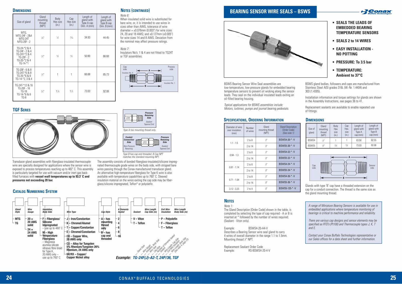
BEARING SENSOR WIRE SEALS – BSWS
NOTES
• SEALS THE LEADS OF EMBEDDED BEARING TEMPERATURE SENSORS
• SEALS 2 to 14 WIRES
• EASY INSTALLATION - NO POTTING
• PRESSURE: To 3.5 bar
• TEMPERATURE: Ambient to 37°C
BSWS Bearing Sensor Wire Seal assemblies are low-temperature, low-pressure glands for embedded bearingtemperature sensors to prevent oil wicking along the sensorleads. They seal on the individual insulated leads exiting an oil-filled bearing housing.
Typical applications for BSWS assemblies include: Motors, turbines, pumps and journal bearing pedestals.
BSWS gland bodies, followers and caps are manufactured fromStainless Steel AISI grades 316L (W.-Nr. 1.4404) and 303 (1.4305).
Installation information and torque settings for glands are shownin the Assembly Instructions, see pages 36 to 41.
Replacement sealants are available to enable repeated use of fittings.
Note 1:The Gland Description [Order Code] shown in the table, is completed by selecting the type of cap required - A or B is inserted at * followed by the number of wires required. (Sealant - Viton only).
Example: BSWS4-20-A4-VDescribes a Bearing Sensor wire seal gland to carry 4 wires of overall diameter in the range 1.1 to 1.5mm. Mounting thread 1⁄2" NPT.
Replacement Sealant Order CodeExample: RS-BSWS4-20-4-V
Glands with type ‘B’ cap have a threaded extension on thecap for a conduit connection. The thread is the same size asthe gland mounting thread.
A range of Miniature Bearing Sensors is available for use inembedded applications where temperature monitoring ofbearings is critical to machine performance and reliability.
There are various cap designs and sensor elements may be specified as RTD’s (Pt100) and Thermocouple types J, K, Tand E.
Contact your Conax Buffalo Technologies representative orour Sales offices for a data sheet and further information.
Conduit PressureConnection Retaining
Side Side
Non-Pressure SealantRetaining Tapered End
PressureRetaining
Side
SealantTapered End
Type A has mounting thread only.
Type B has cap end threaded. B Cap NPTmatches the standard mounting NPT.
Capside
Sensorside
A
B
A
B
Capside
Processside
Insulator No. 1
Insulator No. 4
B U F FA L O T E C H N O L O G I E S

26 C O N A X ® 27
SINGLE AND MULTIPLE TUBE OR PROBE SEALING –PGS, SPG, & DSPG GLANDS WITH SPLIT INTERNAL COMPONENTS SPECIFICATIONS, ORDERING INFORMATION NOTES
PGS GLANDS
SPG & DSPG GLANDS
Gland Description[Order Code](See note 1)
PG2S - 062 - * - * *
PG2S - 093 - * - * *
PG4S - 093 - * - * *
PG2S - 118 - * - * *
PG4S - 118 - * - * *
PG2S - 125 - * - * *
PG4S - 125 - * - * *
PG2S - 187 - * - * *
PG4S - 187 - * - * *
PG5S - 187 - * - * *
PG2S - 236 - * - * *
PG4S - 236 - * - * *
PG5S - 236 - * - * *
PG2S - 250 - * - * *
PG4S - 250 - * - * *
PG5S - 250 - * - * *
PG4S - 312 - * - * *
PG4S - 375 - * - * *
PG5S - 375 - * - * *
PG5S - 500 - * - * *
Viton(V)
690
660
690
500
690
500
690
310
660
145
200
100
110
200
100
110
80
35
70
55
Lava(L)
690
690
690
690
690
690
690
690
690
660
550
690
500
550
690
500
690
690
330
250
Diameter ofelement
to be sealed(See note 3)
mm in.
0.062
0.093
3.0
0.125
0.187
6.0
0.250
0.312
0.375
0.500
Gland mounting
thread (NPT)
1⁄4"
1 ⁄4"
1 ⁄2"
1 ⁄4"
1 ⁄2"
1 ⁄4"
1 ⁄2"
1 ⁄4"
1 ⁄2"
3 ⁄4"
1 ⁄4"
1 ⁄2"
3 ⁄4"
1 ⁄4"
1 ⁄2"
3 ⁄4"
1 ⁄2"
1 ⁄2"
3 ⁄4"
3 ⁄4"
Pressure rating by sealant (bar)(See note 3)
0.5mm0.020"
5
7
11
-
-
-
0.032"
4
5
10
5
9
17
1.0mm0.040"
3
5
9
5
9
17
0.062"
2
4
7
4
5
13
0.093"
2
3
5
-
5
9
0.125"
-
2
4
-
4
6
0.187"
-
-
3
-
-
5
0.250"
-
-
2
-
-
4
Teflon(T)
220
130
690
95
690
95
690
60
500
170
50
165
130
50
165
130
135
95
80
65
Grafoil(G)
690
660
690
500
690
500
690
330
690
80
250
345
60
250
345
60
345
220
40
30
Glandmounting
thread(NPT)
1 ⁄4"
1 ⁄2"
3 ⁄4"
1 ⁄4"
1 ⁄2"3 ⁄4"
Gland Description[Order Code](See note 2)
SPG75 -Ø-*-**
SPG100-Ø-*-**
SPG150-Ø-*-**
DSPG75-Ø-*-**
DSPG100-Ø-*-**
DSPG150-Ø-*-**
Maximum number of elements for each diameter of element(See Notes 3, 4 & 5)
Size of gland
PG2S, SPG75& DSPG75
PG4S, SPG100& DSPG100
PG5S, SPG150& DSPG150
Glandmounting
thread(NPT)
1⁄4"
1⁄2"
3⁄4"
Length ofgland withtype A cap
Dim. A (mm)
50.80
65.09
84.14
Length ofgland withtype B cap
Dim. B (mm)
66.68
85.73
106.36
Internal dia.(Max.
element dia.)Dim. C
mm [in.]
8.0 [0.32]
11.0 [0.45]
19.5 [0.78]
Cap &Body
Hex sizes(in.)
3⁄4
1
11⁄2
DIMENSIONS
Sealant(Sealant Code)
Viton (V)
Teflon (T)
Lava (L)
Grafoil (G)
Temperature range
-20ºC to +232ºC
-185ºC to +232ºC
-185ºC to + 870ºC
-240ºC to +495ºC(to +1650ºC in a reducing atmos.)
Pressure range@ 20ºC
Vacuum to 690 bar
Vacuum to 550 bar
1bar to 690 bar
Vacuum to 690 bar
SEALANT SELECTION GUIDE
• PGS SEALS A SINGLE ELEMENT
SPG SEALS 2 TO 11 ELEMENTS
DSPG SEALS 4 TO 17 ELEMENTS
• SPLIT INTERNAL COMPONENTSFOR EASY INSTALLATION
• PRESSURE:Vacuum to 690 bar
• TEMPERATURE:-240°C to +870°C
• FOR GAS OR LIQUID
• ‘SOFT’SEALANTS REPLACEABLE WITHOUT REMOVING ELEMENTS
• ELEMENTS INDEPENDENTLY ADJUSTABLE
• STAINLESS STEEL FITTINGS
Note 1:The Gland Description [Order Code] shown in thePGS table is completed by selecting the type ofcap required - A or B is inserted at *. The codeletter for the sealant selected is inserted at **.
Note 2:The Gland Description [Order Code) shown in the SPG & DSPG table is completed by insertingthe diameter of the element required (in thou-sandths of an inch) at ø. Select the type of cap required - A or B is inserted at * followed by the number of elements required. The code letter for the sealant selected is inserted at **.(See opposite page for sealant information).
Examples: PG4S-093-A-VSPG75-062-A2-TDSPG150-125-A6-L
Replacement Sealant Order CodeExamples: RS-PG4S-093-V
RS-SPG75-062-2-TRS-DSPG15O-125-6-L
Replacement Packing Set Order CodeExamples: RPS-PG4S-093-V
RPS-SPG 75-062-2-LRPS-DSPG150-125-6-L
Note 3:Tolerance of tube or probe diameter = ±0.076mm(0.003") for elements <1.0mm (0.040") and±0.127mm (0.005") for elements _>1.0mm.Deviation from the nominal may affect pressure ratings.
Note 4:SPG and DSPG gland assemblies are not available in all sealant materials and hole densities. SPG75 and all DSPG75 sizes are not available with Grafoil sealants. Where no value is shown in the table the option is not available.
Note 5: For pressure ratings for SPG & DSPG glandsplease consult Conax. All pressure and vacuum ratings are determined at 20°C with a stainless steel rod as the element. For vacuum ratings see page 42.
PGS, SPG and DSPG glands are pressure and vacuum sealingassemblies where the sealants and the stainless steel followersand seats are split. PGS glands are for a single element and SPGglands are for multiple elements, their internal components have asingle split. DSPG glands are for multiple elements and have inter-nal components with a double split.
Applications for PGS, SPG & DSPG glands include: Sealing of sin-gle and multiple thermocouples, thermistor probes etc., when theelements to be sealed can pass through the gland body but notthrough the internal components. For example, process ends ofsensors may be of a larger diameter than at the sealing point orthere may be connectors to pass through the gland. These glandsmay also be used if elements are long and difficult to handle, orthere are other installation constraints.
PGS, SPG & DSPG gland bodies, followers, caps and seats aremanufactured from Stainless Steel AISI grades 316L (W.-Nr.1.4404) and 303 (1.4305). Other materials may be specified see page 42.
Conax pressure and vacuum sealing assemblies can be specified for use in a range of temperature, pressure and environmental situations by choosing a sealant that is suitable for the application. Replacement split sealants and replacementpacking sets (split sealant with split follower and seat) are available to enable repeated use of fittings.
Capside
Processside
A
B
C
SPG & DSPG
PGS
B U F FA L O T E C H N O L O G I E S
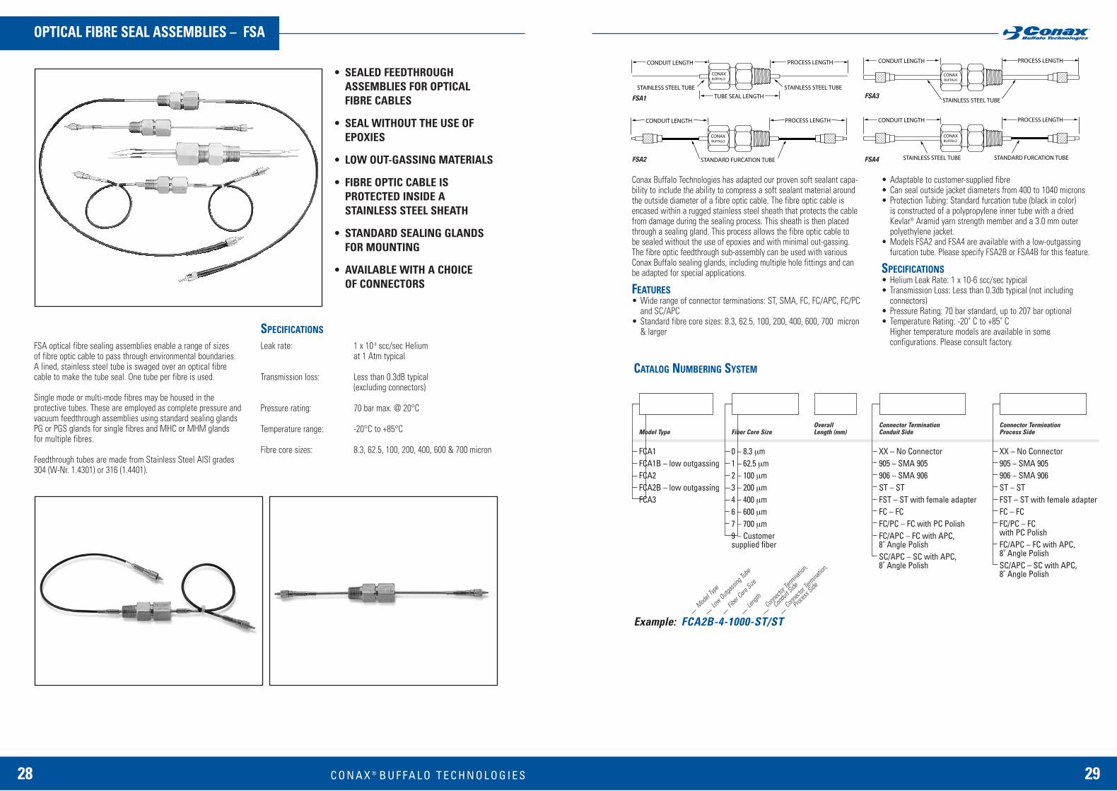
28 C O N A X ® 29
OPTICAL FIBRE SEAL ASSEMBLIES – FSA
SPECIFICATIONS
CATALOG NUMBERING SYSTEM
• SEALED FEEDTHROUGH ASSEMBLIES FOR OPTICAL FIBRE CABLES
• SEAL WITHOUT THE USE OF EPOXIES
• LOW OUT-GASSING MATERIALS
• FIBRE OPTIC CABLE IS PROTECTED INSIDE A STAINLESS STEEL SHEATH
• STANDARD SEALING GLANDS FOR MOUNTING
• AVAILABLE WITH A CHOICE OF CONNECTORS
FSA optical fibre sealing assemblies enable a range of sizes of fibre optic cable to pass through environmental boundaries. A lined, stainless steel tube is swaged over an optical fibrecable to make the tube seal. One tube per fibre is used.
Single mode or multi-mode fibres may be housed in the protective tubes. These are employed as complete pressure andvacuum feedthrough assemblies using standard sealing glandsPG or PGS glands for single fibres and MHC or MHM glands for multiple fibres.
Feedthrough tubes are made from Stainless Steel AlSl grades304 (W-Nr. 1.4301) or 316 (1.4401).
Leak rate: 1 x 10⁻⁶ scc/sec Helium at 1 Atm typical
Transmission loss: Less than 0.3dB typical(excluding connectors)
Pressure rating: 70 bar max. @ 20°C
Temperature range: -20°C to +85°C
Fibre core sizes: 8.3, 62.5, 100, 200, 400, 600 & 700 micron
Conax Buffalo Technologies has adapted our proven soft sealant capa-bility to include the ability to compress a soft sealant material aroundthe outside diameter of a fibre optic cable. The fibre optic cable isencased within a rugged stainless steel sheath that protects the cablefrom damage during the sealing process. This sheath is then placedthrough a sealing gland. This process allows the fibre optic cable to be sealed without the use of epoxies and with minimal out-gassing.The fibre optic feedthrough sub-assembly can be used with variousConax Buffalo sealing glands, including multiple hole fittings and can be adapted for special applications.
FEATURES• Wide range of connector terminations: ST, SMA, FC, FC/APC, FC/PC
and SC/APC• Standard fibre core sizes: 8.3, 62.5, 100, 200, 400, 600, 700 micron
& larger
FSA1
FSA2
FSA3
FSA4
• Adaptable to customer-supplied fibre• Can seal outside jacket diameters from 400 to 1040 microns• Protection Tubing: Standard furcation tube (black in color)
is constructed of a polypropylene inner tube with a driedKevlar® Aramid yarn strength member and a 3.0 mm outerpolyethylene jacket.
• Models FSA2 and FSA4 are available with a low-outgassing furcation tube. Please specify FSA2B or FSA4B for this feature.
SPECIFICATIONS• Helium Leak Rate: 1 x 10⁻⁶ scc/sec typical• Transmission Loss: Less than 0.3db typical (not including
connectors)• Pressure Rating: 70 bar standard, up to 207 bar optional• Temperature Rating: -20˚ C to +85˚ C
Higher temperature models are available in some configurations. Please consult factory.
Model Type
FCA1FCA1B – low outgassingFCA2 FCA2B – low outgassingFCA3
Model
Type
Conne
ctor T
ermina
tion,
Condu
it Side
Conne
ctor T
ermina
tion,
Proces
s Side
Low Outg
assing
Tube
Fiber
Core Size
Length
Example: FCA2B-4-1000-ST/ST
OverallLength (mm)Fiber Core Size
0 – 8.3 µm1 – 62.5 µm2 – 100 µm3 – 200 µm4 – 400 µm6 – 600 µm7 – 700 µm9 – Customersupplied fiber
Connector Termination Process Side
XX – No Connector905 – SMA 905906 – SMA 906ST – STFST – ST with female adapterFC – FCFC/PC – FC with PC PolishFC/APC – FC with APC,8˚ Angle PolishSC/APC – SC with APC, 8˚ Angle Polish
Connector TerminationConduit Side
XX – No Connector905 – SMA 905906 – SMA 906ST – STFST – ST with female adapterFC – FCFC/PC – FC with PC PolishFC/APC – FC with APC,8˚ Angle PolishSC/APC – SC with APC, 8˚ Angle Polish
B U F FA L O T E C H N O L O G I E S

30 C O N A X ® 31
CATALOG NUMBERING SYSTEM
NOTES
• CONTINUOUS WIREFEEDTHROUGHS FOR THERMOCOUPLES, RTD’SAND OTHER LOW-VOLTAGE INSTRUMENTATION
• 12, 24, 40 OR 60, BUNDLED,24 AWG, TEFLON-COATED COPPER OR THERMOCOUPLE MATERIAL WIRES
• NO EPOXY AND NO POTTING
• PRESSURE: Vacuum to 345 bar
• TEMPERATURE -80°C to +120°C
• RATED 1OOVdc @ 500mA
• SINGLE OR MULTIPLEFEEDTHROUGHS IN A SINGLE SEALING GLAND
HD feedthrough assemblies comprise a Conax BuffaloTechnologies high-density, wire feedthrough sealed with a sealing gland.
A Teflon-lined, stainless steel tube is swaged over 12, 24, 40 or60, bundled, 24AWG, solid, Teflon-coated insulated, copper and or thermocouple material wires, to make the high-densityfeedthrough. The swaged tube is mounted in a sealing gland.
Assemblies are supplied with a minimum of 600mm of wire oneach side of the feedthrough, longer lengths can be specified torequirements.
Typical applications include sealing of wires exiting pressure vessels, instruments, furnaces, sterilisers and reactors.
Feedthrough tubes are made from Stainless Steel AISI grades 304(W-Nr. 1.4301) or 316 (1.4401).
Feedthrough tube diameter: 4.75mm (HD18)6.35mm (HD25)7.92mm (HD31)9.53mm (HD37)
Tube length: 114mm
Voltage / current rating: 1OOVdc / 500mA
Temperature range: -80°C to +120°C
Pressure rating: 345 bar max. © 20°CFor higher pressure applications please consult your Conaxrepresentative or our Sales offices. For vacuum rating see page 42.
Leak rate: 1 X 10⁻⁹ scc/sec, Helium at 20°C,1 Atm. supplied
Vacuum Rating: 5 X 10⁻³ mtorr @ 20°C
Note 1:Any combination of thermocouple pairs and single copper wires maybe specified. Copper wires are counted individually and thermocouple wires are counted as pairs.
Note 2:To specify a combination of different types of thermocouple pairsand copper wires, identify the combination required in the style ofthe following examples:
T/C pairs and individual copper wires are marked on each side ofthe feedthrough for identification.
Note 3:For wire types R, S, B and C contact Conax Buffalo Technologies.
Note 4:Conax® Buffalo Technologies can provide numerous options for themanagement of wires in our sealing assemblies:
• Wire Markers with customer nomenclature for easy wire identification of multiple wires
• Twisting of wires in pairs or other groupings for easier identification and management
• Wire Jackets/Sleeving• Hot Junctions – exposed or encapsulated
Please consult your Conax Buffalo Technologies sales engineer for details.
HIGH DENSITY, MECHANICALLY-SEALED, WIRE FEEDTHROUGH ASSEMBLIES – HDDIMENSIONS, SPECIFICATIONS
PG gland with a high-density feedthrough
MHM gland with multiplehigh-density feedthrough
Gland Type(Optional)
Select a gland with a bore size that fits thefeedthrough diameter. See the appropriatecatalog section for proper gland callout. If gland is not required, omit gland callout.Will accept PG, MK, MHM or split gland.
Style
HD
Wire LengthCap Side (m)
Wire LengthBody Side (m)
Feedthrough Diameter
18 – 0.187" OD25 – 0.250" OD31 – 0.312" OD37 – 0.375" OD
Tube Length
450 - 4.5"
Custom tubelengths alsoavailable.
Number of Conductors
12 – for HD18 = 12 totalconductors or 6 T/C pairs24 – for HD25 = 24 totalconductors or 12 T/C pairs 40 – for HD31 = 40 totalconductors or 20 T/C pairs60 – for HD37 = 60 totalconductors or 30 T/C pairs
Wire Type
J – Iron/ConstantanK – Chromel/AlumelT – Copper/ConstantanE – Chromel/ConstantanCU – Copper Wire
Consult factory for CX, RX/SX, or other wire typecombinations.
Style
Gland T
ype
Feedth
rough
Diamete
r
Numbe
r of C
ondu
ctors
Tube L
ength
Wire Le
ngth,
Cap Side
Wire Le
ngth,
Body S
ide
Example: HD25-450(12K)PG2AT, 0.6m/0.6m(with gland)Example: HD25-450(6K/12CU), 0.6m/2.0m(without gland)
Example: HD25-450(24CU)MHM5A4T, 1.0m/1.0m(with multiple feedthrough gland)
Wire Ty
pe
B U F FA L O T E C H N O L O G I E S
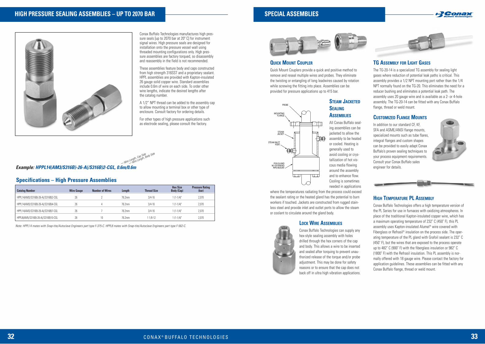
32 C O N A X ® 33
HIGH PRESSURE SEALING ASSEMBLIES – UP TO 2070 BAR SPECIAL ASSEMBLIES
QUICK MOUNT COUPLER
Quick Mount Couplers provide a quick and positive method toremove and reseal multiple wires and probes. They eliminate the twisting or entangling of long leadwires caused by rotationwhile screwing the fitting into place. Assemblies can be provided for pressure applications up to 415 bar.
STEAM JACKETED
SEALING
ASSEMBLIES
All Conax Buffalo seal-ing assemblies can bejacketed to allow theassembly to be heatedor cooled. Heating isgenerally used toavoid cooling or crys-tallization of hot vis-cous media flowingaround the assemblyand to enhance flow.Cooling is sometimesneeded in applications
where the temperatures radiating from the process could exceedthe sealant rating or the heated gland has the potential to burnworkers if touched. Jackets are constructed from rugged stain-less steel and provide inlet and outlet ports to allow the steamor coolant to circulate around the gland body.
LOCK WIRE ASSEMBLIES
Conax Buffalo Technologies can supply anyhex-style sealing assembly with holesdrilled through the hex corners of the capand body. This allows a wire to be insertedand sealed after torquing to prevent unau-thorized release of the torque and/or probeadjustment. This may be done for safetyreasons or to ensure that the cap does notback off in ultra high vibration applications.
TG ASSEMBLY FOR LIGHT GASES
The TG-20-14 is a specialized TG assembly for sealing lightgases where reduction of potential leak paths is critical. Thisassembly provides a 1/2 NPT mounting port rather than the 1/4NPT normally found on the TG-20. This eliminates the need for areducer bushing and eliminates a potential leak path. Theassembly uses 20 gauge wire and is available as a 2- or 4-holeassembly. The TG-20-14 can be fitted with any Conax Buffaloflange, thread or weld mount.
CUSTOMIZED FLANGE MOUNTS
In addition to our standard CF, KF, SFA and ASME/ANSI flange mounts,specialized mounts such as tube flares,integral flanges and custom shapescan be provided to easily adapt ConaxBuffalo’s proven sealing techniques toyour process equipment requirements.Consult your Conax Buffalo sales engineer for details.
HIGH TEMPERATURE PL ASSEMBLY
Conax Buffalo Technologies offers a high temperature version ofthe PL Series for use in furnaces with oxidizing atmospheres. Inplace of the traditional Kapton-insulated copper wire, which hasa maximum operating temperature of 232˚ C (450˚ F), this PLassembly uses Kapton-insulated Alumel® wire covered withFiberglass or Refrasil® insulation on the process side. The oper-ating temperature of the PL gland with Grafoil sealant is 232˚ C(450˚ F), but the wires that are exposed to the process operateup to 482˚ C (900˚ F) with the fiberglass insulation or 982˚ C(1800˚ F) with the Refrasil insulation. This PL assembly is nor-mally offered with 18 gauge wire. Please contact the factory forapplication guidelines. These assemblies can be fitted with anyConax Buffalo flange, thread or weld mount.
Conax Buffalo Technologies manufactures high pres-sure seals [up to 2070 bar at 20º C] for instrumentsignal wires. High pressure seals are designed forinstallation onto the pressure vessel wall usingthreaded mounting configurations only. High pres-sure assemblies are factory torqued, so disassemblyand reassembly in the field is not recommended.
These assemblies feature body and caps constructedfrom high strength 316SST and a proprietary sealant.HPPL assemblies are provided with Kapton-insulated26 gauge solid copper wire. Standard assembliesinclude 0.6m of wire on each side. To order other wire lengths, indicate the desired lengths after the catalog number.
A 1/2” NPT thread can be added to the assembly capto allow mounting a terminal box or other type ofenclosure. Consult factory for ordering details.
For other types of high pressure applications such as electrode sealing, please consult the factory.
Specifications – High Pressure Assemblies Hex Size Pressure Rating
Catalog Number Wire Gauge Number of Wires Length Thread Size Body (Cap) (bar)
HPPL14(AM3/S316B)-26-A(/S316B)2-CGL 26 2 76.2mm 3/4-16 1 (1-1/4)" 2,070
HPPL14(AM3/S316B)-26-A(/S316B)4-CGL 26 4 76.2mm 3/4-16 1 (1-1/4)" 2,070
HPPL14(AM3/S316B)-26-A(/S316B)7-CGL 26 7 76.2mm 3/4-16 1 (1-1/4)" 2,070
HPPL8(AM5/S316B)-26-A(/S316B)10-CGL 26 10 76.2mm 1 1/8-12 1 (1-1/4)" 2,070
Note: HPPL14 mates with Snap-tite/Autoclave Engineers part type F-375-C. HPPL8 mates with Snap-tite/Autoclave Engineers part type F-562-C.
Example: HPPL14(AM3/S316B)-26-A(/S316B)2-CGL, 0.6m/0.6mWire Length, Cap Side
Wire Length, Body Side
B U F FA L O T E C H N O L O G I E S

POWER LEAD/INSULATED WIRE
Conax Buffalo can supply bulk Kapton-insulated, solidconductor power lead wire, ratedto 600 volts, in wire gauges from20 to 8. Minimum order is 15m.
Electrode Amperage Rating Nuts/WashersCopper 20 to 525 amps BrassNickel 8 to 240 amps Stainless SteelStainless Steel 3 to 72 amps Stainless Steel
3534 C O N A X ® B U F FA L O T E C H N O L O G I E S
CUSTOM DESIGN SEALING ASSEMBLIES ACCESSORIES
The standard ranges of sealing gland assemblies shown in thiscatalogue, can be customised through the choice of special sealants, the use of materials other than AISI grades316L and 303 stainless steel for bodies and other components;and by specifying optional mounting and cap threads.
Diverse mounting styles
Conax sealing glands can be customised for ‘0-ring’, flared tubeor flange mounting. This diversity enables our engineers to adaptour proven sealing techniques with ease, to individual processequipment requirements for pressure, vacuum and environmentalsealing applications.
Hazard environment sealing
The Conax HL gland is designed for sealing protection in a widevariety of hazardous environments. The HL Gland has been CSA®
certified in the US and Canada for use in hazardous locationsdefined by the NEC® as Class I Groups B, C, and D, Class IIGroups E, F and G, and Class III.
HL Glands are suitable for gas or liquid, feature a Grafoil®
sealant, come in two sizes (small 1/2” NPT and large 3/4” NPT),provide a temperature range from -20°C to + 55°C and areatmospheric to 35 bar.
This sealing gland is designed to replace Chico® and other similarconduit sealing compound fittings commonly used in hazardousenvironments. With a mechanically-sealed Conax HL gland, youwill not have to be concerned about cracks that allow gases orliquids to leak, causing corrosion to instrumentation and thepotential for explosive gases of liquid to ignite when in the presence of instrumentation.
In addition to these variations, glands can be provided for non-threaded mounting and for specific applications where standardgland designs, or modified versions, cannot meet customers’requirements. Various examples of our design and manufacturingexpertise are shown below.
The sealing glands presented in this catalogue are all available in direct weld-mounting designs. This is achieved by machining of the standard mounting thread on glands, or, by manufacturing glands with weld-necks to precisely the length and diameter required. This option is often required for high-vacuum applications or where thread-freemounting is needed.
Electrode sealing
(a) This EG-750 gland was designed for installing large powerleads into vacuum chambers. It is rated from 6.67 x 1O-4 Pa to12.5 MPa (125 bar). This gland was initially designed as a special development for a specific application. It is now a standard product in the EG range of electrode sealing assemblies (see page 14).
(b) This custom-made 25mm dia. gland was designed and manufactured to carry 4kV ac at 230°C in high vacuum.
Part Number Gauge44-0098-020-CU 2044-0098-018-CU 1844-0098-016-CU 1644-0098-014-CU 1444-0098-012-CU 1244-0098-010-CU 1044-0098-008-CU 8REPLACEMENT INSULATORS
In addition to Replacement PackingSets, Conax Buffalo can supplyindividual Alumina (AL2O3) CeramicInsulators appropriate for use withcopper wire, thermocouple wire forthermocouple calibrations J, K E, T,R, S, B and C, or electrodes.
To order replacement insulators, orderInsulator, (Gland) – (Wire Gauge) – (Number of Holes)
Example: Insulator, TG-20-2
Please specify if the insulators are to be used with Grafoil sealants.
THREAD SEAL MATERIALS
Use of mounting threadenvironmental seal materialsmaximizes the efficiency of theNPT seal. Conax Buffalorecommends Teflon tape foruse up to 232˚ C (450˚ F) and Grafoil tape for use between 232˚C (450˚ F) and 482˚ C (900˚ F ).
REPLACEMENTSEALANTSThe replaceable sealant usedin Conax Buffalo sealingassemblies allows repeateduse of the same fitting.Replacement sealants are available in Neoprene, Viton, Teflon, Lavaor Grafoil, depending on the sealing assembly type. Instructions onhow to order replacement sealants are provided in the catalogsection for the appropriate gland series.
REPLACEMENTPACKING SETSReplacement Packing Sets for MHC, TG, PL and EG seriesassemblies consist of onereplacement sealant with theappropriate number of ceramicinsulators for that specificassembly.
Replacement Packing Sets for MHM, SPG, DSPG and PGS seriesassemblies consist of one replacement sealant with a seat and follower.
Replacement sealants provided in the packing sets are available inNeoprene, Viton, Teflon, Lava or Grafoil, depending on the sealingassembly type. Instructions on how to order replacement packing setsare provided in the catalog section for the appropriate gland series.
Length TemperaturePart Number Material Width of Roll Range44-0135-001 Teflon 0.5" 12.0m -184˚ C to +232˚ C
(-300˚ F to +450˚ F)47-0040-001 Grafoil 0.5" 7.5m -240˚ C to +496˚ C
(-400˚ F to +925˚ F)
(a)
(b)
REPLACEMENT CONDUCTORS/ELECTRODES
Conax Buffalo supplies conductors/electrodes for Conax EG and EGT assemblies in stainless steel, copper or nickel and in sizes from 0.093" to 1.00". Each set is supplied with 4 nuts and 4 washers.
To order replacement electrode, order Conductor, (Gland) – (Diameter) – (Material)
Example: Conductor, EGT-093-CU
SEALING GLAND LUBRICATION KIT
Conax Buffalo Technologies sealing assemblies are supplied factory lubricated. This lubricantis used on the internal cap threads and followers to reduce friction at metal-to-metal contactpoints and to ensure maximum transfer of torque for sealant compression when screwing the assembly together. If cleaned before assembly or any time the gland is loosened andretorqued, the assembly should be relubricated. The same lubricant used by the factory canbe purchased in small, one-application disposable packages with the applicator included. The use of this convenient kit ensures consistent sealing performance without the need topurchase and store large quantities of lubricant.

3736 C O N A X ™ B U F FA L O T E C H N O L O G I E S
Sealant
MHC1
MHC2-020 & -032
MHC2-040 & -062
MHC4
MHC5
N / V
27.2 - 34.0
34.0 - 40.8
34.0 - 40.8
61.2 - 68.0
102 - 116
T
27.2 - 34.0
40.8 - 47.6
40.8 - 47.6
68.0 - 74.8
102 - 116
L
40.8 - 47.6
54.4 - 61.2
54.4 - 61.2
170 - 190
272 - 299
G
34.0 - 40.8
47.6 - 54.4
54.4 - 61.2
122 -136
204 - 224
Sealant
MIC
MPG
PG2
PG4
PG5
PG6
PG7
PG8, PG9
N / V
-
6.21 - 6.78
40.8 - 47.6
74.8 - 81.6
74.8 - 81.6
224-231
T
0.79 - 1.02
6.21 - 6.78
20.4 - 27.2
74.8 - 81.6
122 - 136
407 - 441
L
5.08 - 5.65
8.47 - 9.04
54.4 - 61.2
170 - 190
272 - 299
-
G
-
6.21 - 6.78
47.6 - 54.4
122 - 136
122 - 136
-
47.6 per cap screw
Consult Factory
SEALING GLAND ASSEMBLY AND INSTALLATION INSTRUCTIONS
PG GLANDS (INCLUDING MIC AND MPG GLANDS)
MHC GLANDS
TORQUE TABLE (Nm) – PG GLANDS
TORQUE TABLE (Nm) – MHC GLANDS
CAUTION; CONAX BUFFALO TECHNOLOGIES SEALING GLANDS SHOULD BE INSTALLED BY SUITABLY QUALIFIED PERSONNEL IN ACCORDANCE WITH RELEVANT HEALTH & SAFETY RULESAND WITH PROPER REGARD TO SAFE WORKING PRACTICES.
Please read the following notes before installation.
1. These assembly and installation instructions assume thatthere is free access to the process end(s) of element(s) and thatthe assembly of glands can be undertaken before mounting in anenclosure or vessel. Unless otherwise stated, element(s) andcomponents are inserted into gland bodies from the cap threadend. If access is restricted to the opposite end(s) of element(s), if it is necessary to mount the gland body before assembly, or,there are other installation constraints, it may be necessary tochange the order in which the gland components are fitted.Refer to the relevant sealing gland diagram.
2. Unlike conventional compression fittings, Conax gland capsare tightened to a specified torque setting for each type and sizeof gland, according to the sealant material used. Refer to theTorque tables for each type of gland. If glands are over-torquedprobes or wires may be deformed or broken. If glands are undertorqued the desired seal may not be achieved or the maximum pressure rating will not be achieved. A torque wrench should be used.
3. Gland caps may be slackened to adjust element(s) or disassembled to remove element(s) or replace sealants and insulators without removing the gland body from the installation.(Except EG and EGT glands and other installations where theelements cannot pass through the gland body).
4. When gland bodies must be mounted in the vessel or enclosure before assembly, and where installed glands are slackened or disassembled, glands must be torqued or re-torqued when assembled or re-assembled, using a torquewrench on the cap and a spanner or wrench on the gland bodyhex. flats. Glands should not be torqued against the vessel orenclosure mounting. Thread tape is recommended for use ongland mounting threads. PTFE or Teflon tape is commonly usedfor temperatures to 232°C, Grafoil tape may be used for highertemperatures. (See page 35).
5. Gland threads, followers and the inside top face of caps havelubricant applied during manufacture to prevent galling (binding)between component parts. Gland components should not be de-greased prior to assembly and installation. Substitution offactory applied lubricant will affect gland torque values. Thesame lubricant that is applied to each new gland shipped fromthe factory, is available in a single-application, disposable applicator package. Whenever a gland is opened for adjustmentor replacement of the element(s) or sealant, it is recommendedthat this lubricant is re-applied. (See page 35).
6. Glands must not be slackened or disassembled while aninstallation is in use - under pressure, vacuum or other workingconditions. Stub elements to close unused holes in multi-ele-ment glands must be restrained to prevent unwanted ejection.
1. Identify the type of gland to be assembled. Verify that thetotal length of the element to be installed is such that it provides a sufficient length for desired immersion and leads.
2. Place the cap and then the follower over the element (refer to the gland diagrams).
3. Ensure that the correct sealant has been chosen for use at the working pressure, temperature and process environment.Place the sealant over the element.
4. Using a vice, secure the gland body in a vertical position, cap end uppermost. Insert the element through the gland body and slide the follower and sealant into the gland body.Ensure that the sealant is seated.
5. Thread the cap on to the body until finger tight (6 x hex. headcap screws on PG7). Adjust the immersion length of the elementto the desired position. Using a torque wrench, tighten the cap to the specified torque shown in the Torque table for the size of gland and sealant used. Cap screws on PG7 to be progressively tightened in the order 1-4-2-5-3-6.
6. The assembly is now ready for mounting in the vessel, housingor enclosure. Tighten the gland body using a spanner or wrenchon the gland body flats - not on the cap.
1 . Identify the type of gland to be assembled. Verify that thetotal length of the element(s) to be installed are such that theyprovide sufficient length for desired immersion and leads.
2. Place the cap and then the follower over the element(s) (refer to the gland diagrams).
3. Ensure that the correct sealant has been chosen for use at the working pressure, temperature and process environment.Slide insulator 2, then the sealant, then insulator 1 over the element(s), there are individual holes in these components foreach element.
4. Using a vice, secure the gland body in a vertical position, capthread uppermost. Insert the element(s) through the gland bodyand slide the insulators, sealant and follower into the body.
5. Ensure that insulator 1 is pushed in until it is stopped by theshoulder in the gland. Ensure that the sealant is seated and thatinsulator 2 fits inside the follower. As the follower enters thegland body rotate the assembly so that the anti-rotation pin keyways in the body and the follower are aligned. Insert the pin and push in the follower - ensuring that the elements arecorrectly positioned.
6. Thread the cap on to the body until finger tight. Adjust theimmersion length of the element(s) to the desired position(s).Using a torque wrench, tighten the cap to the specified torqueshown in the Torque table for the size of gland and sealant used.
7. The assembly is now ready for mounting in the vessel, housingor enclosure. Tighten the gland body using a spanner or wrenchon the gland body hex. flats - not on the cap.
CAP
2 1
CONDUIT CONNECTIONSIDE
PG glandsexcept PG7, PG8 & PG9
‘EXPLODED, CUT-AWAY’ VIEW OF A TYPICAL GLAND(Example is type MHM)
PG7, PG8, PG9
CAP FOLLOWER SEALANT BODY
6 x 5⁄8 hex. head cap screws
Non-pressureretaining
Sealanttapered end
PROCESSSIDE
BODY
MHC & PLglands
PL glands have Teflonsleeves fitted to the glandbody and cap to preventwire abrasion.
CAP
A or B CAP,(A Type shown)
ANTI-ROTATION PINMulti-element glands only
MOUNTINGTHREAD
FOLLOWER(Split in PGS,SPG & DSPG)
SEALANT(Split in PGS,SPG & DSPG)
SEAT MHM, PGS,SPG & DSPG only
(Split in PGS,SPG & DSPG)
BODY
ELEMENTS
PIN SEALANT
FOLLOWER INSULATORS
BODY

EG and EGT glands are despatched from the factory alreadytorqued to the correct value and ready for installation. It is notnecessary to re-torque these glands. The following instructionsapply to glands that are to be re-assembled, have been orderedto be hand tightened only, or without electrodes.
1. Identify the type of gland to be assembled. Ensure that thecorrect sealant and electrode material have been chosen for useat the working voltage, current, pressure, temperature andprocess environment. Remove the nuts and washers from theelectrode.
2a. Place one ceramic insulator over the electrode or alterna-tive element. Place the sealant* followed by the secondceramic insulator over the electrode.
2b. Place the Teflon, combined sealant/insulator over theelectrode.
3. Using a vice, secure the gland body in a vertical position, capthread end uppermost.
4. Insert the insulators, sealant* and electrode (EG) or the com-bined, sealant/insulator and electrode (EGT) as assembled, intothe cap thread end of the gland body until the ceramic insulatoror Teflon insulator/sealant is stopped by the shoulder in thegland. Hold the electrode to prevent it from dropping through.
* Note: EG-375 and EG-500 Lava sealants are two-piece matingcone and cup designs. Insert the cup tapered end up and thecone tapered end down.
5. Insert the follower. Seat the undercut edge to the face of theinsulator (EG). Thread the cap on to the body until finger tight (6x hex.head cap screws on (EG-750).
6. Make the final electrode adjustment, ensuring that the ceram-ic insulators or sealant/insulator are firmly seated and aligned.Using a torque wrench, tighten the cap to the specified torqueshown in the Torque table for the size of gland and sealant used.(Cap screws on EG-750 to be progressively tightened in the order1-4-2-5-3-6). Extreme care should be taken when torquing EGglands. Caps should be tightened slowly and smoothly to the recommended torque setting.
7. Install the nuts and washers at each end of the electrode. Theassembly is now ready for mounting in the vessel, housing orenclosure. Tighten the gland body using a spanner or wrench onthe gland body flats - not on the cap.
8. Make the electrical connections to the electrode using ring-tongue, lug-type or spade terminals. These are positionedbetween the washers, the nuts should be tightened securely.Application of a proprietary, self-setting locking fluid or paste tothe electrode threads and nuts is recommended, particularlywhen the assembly may be subject to wide temperature varia-tions or vibration.
38 C O N A X ® 39
Size of gland
PG2S, SPG75 & DSPG75
PG4S, SPG100 & DSPG100
PG5S, SPG150 & DSPG150
Internal dia.(Max. element dia.)
mm [in.]
8.0 [0.32]
11.0 [0.45]
19.5 [0.78]
Sealant
SPG75 & DSPG75
SPG100 & DSPG100
SPG150 & DSPG150
N / V
34.0 - 40.8
108 - 122
163 - 177
T
34.0 - 40.8
108 - 122
204 - 224
L
34.0 - 40.8
170 - 190
272 - 299
G
34.0 - 40.8
150 - 163
238 - 306*
* When torquing elements of 1.0mm (0.040") dia. or less with Grafoilsealants, initially torque to 299Nm. After 24 hours re-torque to 306Nm.
Sealant
MHM2
MHM4
MHM5
MHM6
N / V
34 - 41
109 - 122
163 - 177
41-47
T
34 - 41
109 - 122
204 - 224
41-47
L
34 - 41
170 - 190
272 - 299
–
G
34 - 41
150 - 163
238 - 258
41-47
Sealant
EGT-093
EGT-125
EGT-187 & -250
EGT-375 & -500
EGT-750
EGT-1000
T
6.80 - 8.16
13.6 - 20.4
34.0 - 40.8
47.6 - 54.4
102 - 109
6.1 - 6.8 per bolt
Sealant
EG-093
EG-125 & -187
EG-250
EG-312
EG-375 & -500
EG-750
N / V
23.1 - 27.2
34.0 - 40.8
54.4 - 61.2
47.6 - 54.4
68.0 - 74.8
-
T
23.1 - 27.2
34.0 - 40.8
54.4 - 61.2
47.6 - 54.4
68.0 - 74.8
13.6 - 16.3per cap screw
L
13.6 - 16.3
34.0 - 40.8
81.6 - 88.4
68.0 - 74.8
245 - 272*
34.0 - 40.8per cap screw
MHM, PGS, SPG AND DSPG GLANDS EG AND EGT GLANDS
MHM glands
TORQUE TABLE (Nm) - MHM GLANDS
Sealant
PG2S
PG4S
PG5S
N / V
40.8 - 47.6
74.8 - 81.6
74.8 - 81.6
T
28.4 - 27.2
74.8 - 81.6
122.4 - 136
L
54.4 - 61.2
170 - 190
272 - 299
G
47.6 - 54.4
122.4 - 136
122.4 - 136
TORQUE TABLE (Nm) - PGS GLANDS
TORQUE TABLE (Nm) - SPG & DSPG GLANDS
TORQUE TABLE (Nm) - EG GLANDS
TORQUE TABLE (Nm) - EGT GLANDS
EG glands
EGT glands
PGS, SPG, & DSPG glands
1 . Identify the type of gland to be assembled. Verify that thetotal length of the element(s) to be installed are such that theyprovide sufficient length for desired immersion and leads.
Note: Where PGS, SPG and DSPG glands are to be assembledwith element(s) that have a larger section than at the pointwhere they pass through the gland, e.g., a bulb or there arefitted connectors; ensure that the largest dimension willpass through the gland body and cap (allowing for thedimensions of the other elements to be fitted, if applica-ble). (Refer to the table opposite for maximum dimensions).
2. Ensure that the correct sealant has been chosen for use at theworking pressure, temperature and process environment.
3a. Place the cap over the element(s). Slide the follower,then the sealant, then the seat over the element(s), there are individual holes in these components for each element.(Refer to the gland diagrams).
4a. Using a vice, secure the gland body in a vertical position,cap thread uppermost. Insert the element(s) through the glandbody and slide the seat, sealant and follower into the body.
3b. Using a vice, secure the gland body in a vertical position,cap thread uppermost. Pass the element(s) through the glandbody and the cap. This can be done from either direction.(Refer to the gland diagrams).
4b. Assemble the split parts of the seat around theelement(s) and slide the seat into the gland body. Repeat thisprocedure for the split sealant and then the split follower.
5. As the follower enters the gland body rotate the assembly sothat the anti-rotation pin keyways in the body and the followerare aligned. Insert the pin and push in the follower - ensuringthat the elements are correctly positioned. (Not applicable toPGS)
6. Thread the cap on to the body until finger tight. Adjust theimmersion length of the element(s) to the desired position(s).Using a torque wrench, tighten the cap to the specified torqueshown in the Torque table for the size of gland and sealant used.
7. The assembly is now ready for mounting in the vessel, housingor enclosure. Tighten the gland body using a spanner or wrenchon the gland body hex. flats - not on the cap.
Type HD high-density, wire feedthrough assemblies whenordered with glands, are despatched from the factory withglands already assembled on the feedthrough but loose(untorqued). Type FSA optical fibre feedthrough assemblies,when ordered with glands, are despatched from the factory with glands already assembled and torqued to the correct value.These assemblies are ready for installation. It is not necessary to re-torque these glands.
HD and FSA assemblies may be specified with PG or PGS glandsfor single feedthroughs, or MHC (FSA only), MHM, SPG andDSPG glands for multiple feedthroughs. Refer to the assemblyand installation instructions for the relevant gland type usedwhen installing or re-assembling HD and FSA feedthroughs intheir mounting glands.
HD AND FSA ASSEMBLIES
CAP
CONDUIT CONNECTIONSIDE
Non-pressureretaining
Sealanttapered end
PROCESSSIDE
BODY
MHM, PGS,SPG & DSPGglands
PGS glands carry a singleelement and do not havean anti-rotation pin.
CAP PIN SEALANT BODY
FOLLOWER SEAT
EG glandsexcept EG-750
EG-750
CAP SEALANT
FOLLOWER BODY
INSULATOR INSULATOR
EGT glands
CAP FOLLOWER
SINGLE-PIECE TEFLON SEALANT/INSULATOR
BODY
6 x 9⁄16 hex. head cap screws
B U F FA L O T E C H N O L O G I E S

w w w. c o n a x b u f f a l o . c o m
4140 C O N A X ® B U F FA L O T E C H N O L O G I E S
PL GLANDS, TGF AND TG24T ASSEMBLIES BSWS GLANDS
Sealant
BSWS4
BSWS5
V
4.08 - 6.80
16.3 - 24.5
Sealant
MTG
TG-24TG-20-2 & -4
TG-14-1
TG-20-6 & -8TG-18TG-14-2, -3 & -4
TG-20-16TG-14-6 & -8TG-8
N/V
27.2 - 34.0
34.0 - 40.8
34.0 - 40.8
61.2 - 68.0
102 - 116
T
27.2 - 34.0
40.8 - 47.6
40.8 - 47.6
68.0 - 74.8
102 - 116
L
40.8 - 47.6
54.4 - 61.2
54.4 - 61.2
170 - 190
272 - 299
G
34.0 - 40.8
47.6 - 54.4
54.4 - 61.2
122 - 136
204 - 224
AWG
8
10
12
14
16
18
20
OD (mm)
3.26
2.59
2.05
1.63
1.29
1.02
0.81
mm2
8.80
4.65
3.16
1.93
1.30
0.82
0.52
OD (in.)
0.1285
0.1019
0.0808
0.0641
0.0508
0.0403
0.0320
AWG
22
24
26
28
30
32
34
OD (mm)
0.64
0.51
0.40
0.32
0.25
0.20
0.16
mm2
0.32
0.21
0.13
0.081
0.051
0.033
0.020
OD (in.)
0.0253
0.0201
0.0159
0.0126
0.0100
0.0080
0.0063
PL Glands, TGF, and TG24T assemblies, ordered with specifiedwire lengths, are despatched from the factory already torqued tothe correct value and ready for installation. It is not necessary toretorque these glands.
1. Identify the type of gland to be assembled. Verify that thetotal length of the element(s) to be installed are such that theyprovide sufficient length for desired immersion. Place the capover the element(s) (refer to the gland diagram).
2. Ensure that the correct sealant has been chosen for use at the working pressure, temperature and process environment.Slide insulator 4, then the follower, then insulator 3, followed bythe sealant, over the element(s). For gland sizes MTG, TG-24-2,TG-24-4, TG-20-2, TG-20-4 and TG-14-1 only, slide insulator 1over the element(s). There are individual holes in the insulatorsand sealant for each element.
3. Using a vice, secure the gland body in a vertical position, capthread uppermost. Insert the element(s) through the gland bodyand slide the insulators, sealant and follower into the body.
4. Ensure that insulator 2 is pushed in until it is stopped by theshoulder in the gland. Ensure that the sealant is seated and thatinsulator 3 fits inside the follower. As the follower enters thegland body rotate the assembly so that the anti-rotation pin key-ways in the body and the follower are aligned. Insert the pin andpush in the follower - ensuring that the elements are correctlypositioned. For all other gland sizes, not identified in 3. above,slide insulator 1 over the elements and push it into the glandbody from the process side until it is stopped by the shoulder inthe body.
5. Thread the cap on to the body until finger tight. Adjust theimmersion length of the element(s) to the desired position(s).Using a torque wrench, tighten the cap to the specified torqueshown in the Torque table for the size of gland and sealant used.
6. The assembly is now ready for mounting in the vessel, hous-ing or enclosure. Tighten the gland body using a spanner orwrench on the gland body hex. flats - not on the cap.
For PL glands that are to be re-assembled, have been ordered tobe hand tightened only, or are supplied without wires, refer tothe assembly instructions and gland diagram for MHC glands.
1 . Identify the type of gland to be assembled. If the sensorleads have an outer insulation or sleeve, trim this back to the point where it will enter the gland body when installed (see diagram) - thus exposing the individual insulated leads.
2. Install the sensor securely into its housing. Place the glandbody over the leads and mount it in the enclosure or bearinghousing mounting thread. Slide the sealant over the leads into the gland body until seated. There are individual holes for each lead.
3. Place the follower over the leads and push it into the glandbody . Ensure that the wires are correctly positioned.
4. Place the cap over the leads, screw on and tighten it to the specified torque shown in the Torque table for the size of gland used.
TG GLANDS
TORQUE TABLE (Nm) – TG GLANDS
TORQUE TABLE (Nm) – BSWS GLANDS
WIRE SIZE CONVERSION TABLEThe data provided in the following table applies to single core solid drawnwire without insulation.
Specifiers using wire sizes other than AWG may determine the nearestequivalent wire size, within permissible limits of tolerance, by reference to the table, e.g., 0.5mm2 wire size is equivalent to 20 AWG.
Where it is intended to use elements of equivalent od. in place of wire in certain types of glands, the diameter of the element may also be determined from the table. e.g., 18 AWG wire may be substituted with an element 1.0mm (0.040”) diameter. Caution: When calculating equivalentelement sizes for PL glands, allowance must be made for the thickness ofthe Kapton insulation. Refer to page 21, Note 2.
CONVERSION FACTORSTemperature
To convert °F to °C: °C =
To convert °C to °F: °F = +32
To convert °K to °C °C = °K - 273.15To convert °C to °K °K = °C + 273.15
Pressure
To convert psi (lbf/in2) to bar: bar = psi x 0.0689To convert psi (lbf/in2) to Pa: Pa = psi x 6894.76To convert bar to psi (lbf/in2): psi = bar x 14.5To convert Pa to psi (lbf/in2): psi = Pax 0.000145To convert Pa to bar: bar = 1 x 10 Pa
(1 mbar = 100 Pa)
Torque
To convert ft/lb to Newton metres: Nm = ft/lb x 1.36To convert in/lb to Newton metres: Nm = in/lb x 0.113To convert kg/cm to Newton metres: Nm = kg/cm x 0.098To convert Newton metres to ft/lb: ft/lb = Nm x 0.738To convert Newton metres to in/lb: in/lb = Nm x 8.85To convert Newton metres to kg/cm: kg/cm = Nm x 10.2
(°F - 32) x 59
(9 x °C)5CAP
CONDUIT CONNECTIONSIDE
Non-pressureretaining
Sealanttapered end
PROCESSSIDE
BODY
TG glands
CAP FOLLOWER
INSULATORS
SEALANT BODY
BSWS glands
SENSORLEADS CAP FOLLOWER
OUTER INSULATION(if fitted, trim to
approx. length shown)
SEALANT BODY SENSOR
PIN
4 3 2 1