
THE CIVIL AVIATION (RADIO NAVIGATION AIDS) REGULATIONS ...
103
1 STATUTORY INSTRUMENTS 2019 No…………… THE CIVIL AVIATION (RADIO NAVIGATION AIDS) REGULATIONS, 2019. ARRANGEMENT OF REGULATIONS Regulation PART I-PRELIMINARY 1. Title. 2. Application. 3. Interpretation. PART II-GENERAL REQUIREMENTS 4. Requirements for communication, navigation and surveillance facilities. 5. Certification of Air Navigation Service Provider. 6. Application for approval. 7. Sitting and installation. 8. Installation, operation and maintenance of communication, navigation and surveillance systems. 9. Commissioning of facilities. 10. Inspections and audits. 11. Availability and reliability. 12. Test equipment. 13. Record keeping. 14. Documentation. 15. Periodic inspection and testing. 16. Flight inspection. 17. Operation and maintenance plan. 18. Training requirements for communication, navigation and surveillance personnel. 19. Communication, navigation and surveillance personnel requirements. 20. Proficiency certification program. PART III-RADIO NAVIGATION AIDS 21. Standard radio navigation aids. 22. Precision approach radar. 23. Composition of the precision approach radar systems. 24. Specifications for precision approach radar elements. 25. Specifications for surveillance radar element. 26. Provision of information on the operational status of radio navigation aids. 27. Power supply for radio navigation aids and communication systems. 28. Human factors considerations. 29. Basic requirements for instrument landing system- composition. 30. Operational status indications. 31. Basic requirements for instrument landing system- construction and adjustment. 32. Localizer and glide path components of facility performance categories. 33. ILS level of safety.
Transcript of THE CIVIL AVIATION (RADIO NAVIGATION AIDS) REGULATIONS ...

1
STATUTORY INSTRUMENTS
2019 No……………
THE CIVIL AVIATION (RADIO NAVIGATION AIDS) REGULATIONS, 2019.
ARRANGEMENT OF REGULATIONS
Regulation
PART I-PRELIMINARY
1. Title.
2. Application.
3. Interpretation.
PART II-GENERAL REQUIREMENTS 4. Requirements for communication, navigation and surveillance facilities.
5. Certification of Air Navigation Service Provider.
6. Application for approval.
7. Sitting and installation.
8. Installation, operation and maintenance of communication, navigation and
surveillance systems.
9. Commissioning of facilities.
10. Inspections and audits.
11. Availability and reliability.
12. Test equipment.
13. Record keeping.
14. Documentation.
15. Periodic inspection and testing.
16. Flight inspection.
17. Operation and maintenance plan.
18. Training requirements for communication, navigation and surveillance personnel.
19. Communication, navigation and surveillance personnel requirements.
20. Proficiency certification program.
PART III-RADIO NAVIGATION AIDS 21. Standard radio navigation aids.
22. Precision approach radar.
23. Composition of the precision approach radar systems.
24. Specifications for precision approach radar elements.
25. Specifications for surveillance radar element.
26. Provision of information on the operational status of radio navigation aids.
27. Power supply for radio navigation aids and communication systems.
28. Human factors considerations.
29. Basic requirements for instrument landing system- composition.
30. Operational status indications.
31. Basic requirements for instrument landing system- construction and adjustment.
32. Localizer and glide path components of facility performance categories.
33. ILS level of safety.

2
34. Two ILS facilities serving opposite ends of a single runway.
35. VHF localizer and associated monitor specifications.
36. UHF glide path and associated monitor specifications.
37. Localizer and glide path frequency pairing.
38. VHF marker beacons specifications.
39. VHF Omni directional range specifications.
40. Non directional radio beacon specifications.
41. UHF distance measuring equipment.
42. DME composition.
43. UHF distance measuring equipment specifications.
44. En-route VHF marker beacon 75 MHz specifications.
PART IV-REQUIREMENTS FOR THE GLOBAL NAVIGATION SATELLITE
SYSTEM (GNSS)
45. Functions of GNSS.
46. Global navigation satellite system elements.
47. Space and time reference.
48. Signal-in-space performance.
49. Global navigation satellite system elements specifications.
50. Resistance to interference.
51. System characteristics of airborne ADF receiving systems.
PART V-EXEMPTIONS
52. Requirements for application for exemption.
53. Review and publication.
54. Evaluation of the request.
PART VI-GENERAL
55. Drug and alcohol testing and reporting.
56. Change of name.
57. Change of address.
58. Replacement of documents.
59. Use and retention of documents and records.
60. Reports of violation.
61. Failure to comply with direction.
62. Aeronautical fees.
PART VII-OFFENCES AND PENALTIES
63. Contravention of Regulations.
64. Penalties.
65. Appeal.

3
SCHEDULES
SCHEDULE 1-SPECIFICATION FOR PRECISION APPROACH RADAR SYSTEM
SCHEDULE 2- VHF MARKER BEACONS
SCHEDULE 3- SPECIFICATIONS FOR VHF LOCALIZER AND ASSOCIATED
MONITOR
SCHEDULE 4- UHF GLIDE PATH EQUIPMENT AND ASSOCIATED MONITOR
SCHEDULE 5- SPECIFICATION FOR VHF OMNI DIRECTIONAL RANGE (VOR)
SCHEDULE 6-SPECIFICATION FOR NON-DIRECTIONAL RADIO BEACON (NDB)
SCHEDULE 7- SPECIFICATION FOR UHF DISTANCE MEASURING EQUIPMENT
(DME)
SCHEDULE 8- SPECIFICATION FOR EN-ROUTE VHF MARKER BEACONS (75 MHZ)
SCHEDULE 9- REQUIREMENTS FOR THE GLOBAL NAVIGATION SATELLITE
SYSTEM (GNSS)
SCHEDULE 10- SYSTEM CHARACTERISTICS OF AIRBORNE ADF RECEIVING
SYSTEMS

4
STATUTORY INSTRUMENTS
2019 No……………
The Civil Aviation (Radio Navigation Aids) Regulations, 2019.
(Under section 61 of the Civil Aviation Authority Act, Cap 354)
In EXERCISE of the powers conferred on the Minister by section 61 of the Civil Aviation
Authority Act, Cap 354, and on the recommendation of the Civil Aviation Authority, these
Regulations are made this…………………..day of…………………2019.
PART I-PRELIMINARY
1. Title.
These Regulations may be cited as the Civil Aviation (Radio Navigation Aids) Regulations,
2019.
2. Application.
These Regulations apply to a person providing communication, navigation and surveillance
services within designated air spaces and aerodromes in Uganda.
3. Interpretation.
In these Regulations unless the context otherwise requires-
“aircraft-based augmentation system” means an augmentation system that augments and
integrates the information obtained from the other global navigation satellite system elements
with information available on board the aircraft;
“air navigation services” means services provided to air traffic during all phases of operations
including air traffic management, communications, navigation and surveillance, search and
rescue, aeronautical information services and construction of instrument flight procedures;
“Air Navigation Services Provider” means a directorate in the authority designated for an
independent entity for the purposes of operating and managing air navigation services;
“alert” means an indication provided to other aircraft systems or annunciation to the pilot to
identify an operating parameter of a navigation system that is out of tolerance;
“alert limit” means the error tolerance that should not be exceeded without issuing an alert for
a given parameter measurement;
“altitude” means the vertical distance of a level, a point or an object considered as a point,
measured from mean sea level;
“angular displacement sensitivity” means the ratio of measured difference in depth
modulation to the corresponding angular displacement from the appropriate reference line;

5
“antenna port” means a point where the received signal power is specified-
(a) for an active antenna, the antenna port is a fictitious point between the antenna
elements and the antenna pre-amplifier; and
(b) for a passive antenna, the antenna port is the output of the antenna itself;
“area navigation” means a method of navigation which permits aircraft operation on any
desired flight path within the coverage of ground or space-based navigation aids or within the
limits of the capability of self-contained aids or a combination of these;
“Authority” means the Uganda Civil Aviation Authority established under section 3 of the
Civil Aviation Act;
“average radius of rated coverage” means the radius of a circle having the same area as the
rated coverage;
“back course sector” means the course sector which is situated on the opposite side of the
localizer from the runway;
“certificate” means the certificate for the provision of air navigation services issued by the
Authority under the Civil Aviation (Certification of Air Navigation Services) Regulations,
2019;
“channel of standard accuracy” means the specified level of positioning, velocity and timing
accuracy that is available to any GLONASS user on a continuous, worldwide basis;
“control motion noise” means that portion of the guidance signal error which causes control
surface, wheel and column motion and could affect aircraft attitude angle during coupled
flight, but does not cause aircraft displacement from the desired course or glide path;
“course line” means the locus of points nearest to the runway centre line in any horizontal
plane at which the difference in depth of modulation is zero;
“course sector” means a sector in a horizontal plane containing the course line and limited by
the loci of points nearest to the course line at which the difference in depth of modulation is
0.155;
“difference in depth of modulation” means the percentage modulation depth of the larger
signal minus the percentage modulation depth of the smaller signal, divided by 100;
“DME/N” means a distance measuring equipment, primarily serving operational needs of en-
route or TMA navigation, where the “N” stands for narrow spectrum characteristics;
“DME/P” means the distance measuring element of the MLS, where the “P” stands for
precise distance measurement: the spectrum characteristics are those of DME/N;
“elevation” means the vertical distance of a point or a level, on or affixed to the surface of the
earth, measured from mean sea level;
“essential radio navigation service” means a radio navigation service whose disruption has a
significant impact on operations in the affected airspace or aerodrome;

6
“final approach mode” means the condition of DME/P operation which supports flight
operations in the final approach and runway regions;
“front course sector” means the course sector which is situated on the same side of the
localizer as the runway;
“global navigation satellite system (GNSS)” means a worldwide position and time
determination system that includes one or more satellite constellations, aircraft receivers and
system integrity monitoring, augmented as necessary to support the require navigation
performance for the intended operation;
“global navigation satellite system (GLONASS)” means the satellite navigation system
operated by the Russian Federation;
“global positioning system (GPS)” means the satellite navigation system operated by the
United States;
“GNSS position error” means the difference between the true position and the position
determined by the GNSS receiver;
“ground-based augmentation system” means an augmentation system in which the user
receives augmentation information directly from a ground-based transmitter;
“ground-based regional augmentation system” means an augmentation system in which the
user receives augmentation information directly from one of a group of ground-based
transmitters covering a region;
“half course sector” means the sector in a horizontal plane containing the course line and
limited by the loci of points nearest to the course line at which the DDM is 0.0775;
“height” means the vertical distance of a level, a point or an object considered as a point,
measured from a specified datum;
“human factors principles” means principles which apply to design, certification, training,
operations and maintenance and which seek safe interface between the human and other
system components by proper consideration to human performance;
“ILS glide path” means that locus of points in the vertical plane containing the runway centre
line at which the DDM is zero, which, of all such loci, is the closest to the horizontal plane;
“ILS glide path angle” means the angle between a straight line which represents the mean of
the ILS glide path and the horizontal;
“ILS glide path sector” means the sector in the vertical plane containing the ILS glide path
and limited by the loci of points nearest to the glide path at which the DDM is 0.175;
“ILS point “A”” means a point on the ILS glide path measured along the extended runway
centre line in the approach direction a distance of 7.5 km (4 NM) from the threshold;

7
“ILS point “B”” means a point on the ILS glide path measured along the extended runway
centre line in the approach direction a distance of 1 050 m (3 500 ft) from the threshold;
“ILS point “C”” means a point through which the downward extended straight portion of the
nominal ILS glide path passes at a height of 30 m (100 ft) above the horizontal plane
containing the threshold;
“initial approach mode” means the condition of DME/P operation which supports those flight
operations outside the final approach region and which is interoperable with DME/N;
“key down time” means the time during which a dot or dash of a Morse character is being
transmitted;
“locator” means an LF/MF NDB used as an aid to final approach;
“MLS approach reference datum” means a point on the minimum glide path at a specified
height above the threshold;
“MLS datum point” means the point on the runway centre line closest to the phase centre of
the approach elevation antenna;
“partial rise time” means the time as measured between the 5 and 30 per cent amplitude
points on the leading edge of the pulse envelope;
“path following error” means that portion of the guidance signal error which could cause
aircraft displacement from the desired course and/or glide path;
“performance-based navigation” means area navigation based on performance requirements
for aircraft operating along an ATS route, on an instrument approach procedure or in a
designated airspace;
“pulse code” means the method of differentiating between W, X, Y and Z modes and
between FA and IA modes;
“pulse decay time” means the time as measured between the 90 and 10 per cent amplitude
points on the trailing edge of the pulse envelope;
“pulse duration” means the time interval between the 50 per cent amplitude point on leading
and trailing edges of the pulse envelope;
“pulse rise time” means the time as measured between the 10 and 90 per cent amplitude
points on the leading edge of the pulse envelope;
“radio navigation service” means a service providing guidance information or position data
for the efficient and safe operation of aircraft supported by one or more radio navigation aids;
“rated coverage” means the area surrounding an NDB within which the strength of the
vertical field of the ground wave exceeds the minimum value specified for the geographical
area in which the radio beacon is situated;

8
“reply efficiency” means the ratio of replies transmitted by the transponder to the total of
received valid interrogations;
“search” means the condition which exists when the DME interrogator is attempting to
acquire and lock onto the response to its own interrogations from the selected transponder;
“satellite-based augmentation system (SBAS)” means a wide coverage augmentation system
in which the user receives augmentation information from a satellite-based transmitter;
“standard positioning service” means the specified level of positioning, velocity and timing
accuracy that is available to any global positioning system user on a continuous, worldwide
basis;
“system efficiency” means the ratio of valid replies processed by the interrogator to the total
of its own interrogations;
“time-to-alert” means the maximum allowable time elapsed from the onset of the navigation
system being out of tolerance until the equipment enunciates the alert;
“touchdown” means the point where the nominal glide path intercepts the runway;
“transmission rate” means the average number of pulse pairs transmitted from the
transponder per second;
“two-frequency glide path system” means an ILS glide path in which coverage is achieved by
the use of two independent radiation field patterns spaced on separate carrier frequencies
within the particular glide path channel;
“virtual origin” means the point at which the straight line through the 30 per cent and 5 per
cent amplitude points on the pulse leading edge intersects the 0 per cent amplitude axis.
PART II-GENERAL REQUIREMENTS
4. Requirements for communication, navigation and surveillance facilities.
The installation, commissioning, operation and maintenance of the communication,
navigation and surveillance facilities shall conform to these Regulations.
5. Certification.
A person shall not provide communication, navigation and surveillance services or operate a
facility to support air traffic services without an air navigation services provider certificate
issued in accordance with the Civil Aviation (Certification of Air Navigation Services)
Regulations, 2019.
6. Application for approval.
A person who wishes to provide communication, navigation and surveillance systems or to
operate communication, navigation and surveillance facility in the designated airspace and
aerodromes shall apply to the Authority for approval.

9
7. Sitting and installation.
(1) The Air Navigation Services Provider shall determine the site for
installation of a facility based on operational requirements, construction aspects and
maintainability.
(2) The facility in subregulation (1) shall be installed by personnel
who are qualified in air navigation facilities and who have knowledge of the operations,
testing and maintenance of the communication, navigation and surveillance facilities.
8. Installation, operation and maintenance of communication, navigation and
surveillance systems.
The Air Navigation Service Provider shall establish procedures to ensure that the
communication, navigation and surveillance systems-
(a) are operated, maintained, available and reliable in accordance with
the requirements prescribed by the Authority;
(b) are designed to meet the applicable operational specification for that
facility;
(c) are installed and commissioned as prescribed by the Authority; and
(d) conform to the applicable system characteristics and specifications.
9. Commissioning of facilities.
(1) The Authority shall be involved in the commissioning of communication, navigation
and surveillance facilities to confirm that the facilities meet the standard operating
parameters and these Regulations before commencement of operations.
(2) The Air Navigation Services Provider shall establish procedures to ensure that each
new facility is commissioned to meet the specifications for that facility and is in
compliance with these Regulations.
(3) The Air Navigation Services Provider shall at the time of commissioning a facility
referred to in subregulation (1), validate the system performance of the new facility by
carrying out the necessary tests.
(4) The procedures referred to in subregulation (2) shall include documentation of tests
conducted on the facility prior to commissioning, including those that test the
compliance of the facility with the applicable standards and any flight check required
in compliance with these Regulations.
10. Inspections and audits.
(1) The Authority shall carry out safety inspections and audits on
communication, navigation and surveillance facilities, documents and records of the
communication, navigation and surveillance facilities to determine compliance with
these Regulations.

10
(2) An inspector designated by the Authority shall have unrestricted
access to the communication, navigation and surveillance facilities, records and
documents of the facilities approved under these Regulations to determine compliance
with these Regulations.
11. Availability and reliability.
The communication, navigation and surveillance facilities provider shall provide protected
power supply system, battery back-up, reliable connectivity and air conditioning.
12. Test equipment.
(1) The Air Navigation Service Provider shall provide appropriate tools and test
equipment to personnel to maintain the operation of equipment.
(2) The Air Navigation Service Provider shall establish a procedure to control, calibrate
and maintain the equipment.
(3) The maintenance plan or the operating and maintenance instructions for each facility
shall specify the test equipment requirements for all levels of operation and
maintenance undertaken.
(4) The Air Navigation Service Provider shall use documented procedures established
under subregulation (2) to control, calibrate and maintain test equipment.
13. Record keeping.
The Air Navigation Service Provider shall establish procedures to identify, collect, index,
store, maintain and dispose records covering-
(a) the performance and maintenance history of the facility;
(b) the establishment of the periodic test programmes for the facility;
(c) test equipment required for the measurement of critical performance parameters;
(d) reported or detected facility malfunction;
(e) internal quality assurance review; and
(f) the person authorised to place facilities into operational service.
14. Documentation.
The Air Navigation Service Provider shall-
(a) keep copies of relevant equipment manuals, technical standards, practices,
instructions, maintenance procedures, site logbooks and any other documentation that
are necessary for the provision and operation of the facility;
(b) record all occurrences and actions relating to operation, maintenance, modification,
failure, faults, removal from and restoration to service in the log books; and
(c) establish a procedure for the control of the documentation required under this
regulation.

11
15. Periodic inspection and testing.
(1) The Air Navigation Service Provider shall establish a procedure for the periodic
inspection and testing of the communication, navigation and surveillance systems to
verify that the facility meets the applicable operational requirements and performance
specifications for that facility.
(2) Periodic inspection shall include-
(a) security of the facility and site;
(b) adherence to the approved maintenance programme;
(c) upkeep of the equipment, building, site and site services; and
(d) adequacy of facility records and documentation.
16. Flight inspection.
The Air Navigation Service Provider shall ensure that the radio navigation aids prescribed
under these Regulations are available for use by aircraft engaged in air navigation and are
subjected to periodic ground and flight inspection.
17. Operation and maintenance plan.
(1) The Air Navigation Service Provider shall establish an operation and maintenance
plan for the communication, navigation and surveillance facilities, to meet the safety
requirements prescribed in these Regulations.
(2) The operation and maintenance plan established under subregulation (1) shall provide
for the timely and appropriate detection and warning of system failures and
degradations.
18. Training requirements for communication, navigation and surveillance
personnel.
(1) The Air Navigation Service Provider shall ensure that all its personnel possess the
skills and competencies required in the provision of the communication navigation
and surveillance services.
(2) The Air Navigation Service Provider shall-
(a) develop a training policy and programme for the organization;
(b) maintain training records and plan for the staff; and
(c) conduct periodic review of the training plan.
19. Communication, navigation and surveillance personnel requirements.
(1) The Air Navigation Service Provider shall employ sufficient number of competent
personnel to perform the installation, operation and maintenance of communication,
navigation and surveillance system in the designated airspace and aerodromes.
(2) The Air Navigation Service Provider shall provide in the Manual of Air Navigation
Service Operations an analysis of the personnel required to perform the
12
communication navigation and surveillance services for each facility taking into
account the duties and workload required.
(3) A person shall not perform a function related to installation, operation or
maintenance of a communication, navigation and a surveillance system unless-
(a) that person has successfully completed training in the performance of
that function;
(b) a Air Navigation Service Provider is satisfied that the technical
person is competent in performing that function; and
(c) that person has been certified in accordance with these Regulations.
20. Proficiency certification program.
The Authority shall develop a proficiency certification program of personnel who are
engaged in the installation, operation and maintenance of communication, navigation and
surveillance systems used in the designated airspace and aerodrome.
PART III- RADIO NAVIGATION AIDS
21. Standard radio navigation aids.
(1) The standard radio navigation aids used for air navigation shall include-
(a) the instrument landing system;
(b) the global navigation satellite system;
(c) the VHF omnidirectional radio range;
(d) the non-directional radio beacon;
(e) the distance measuring equipment; and
(f) the en-route VHF marker beacon.
(2) The differences in radio navigation aids specified in subregulation (1) shall be
published in an Aeronautical Information Publication.
(3) The Air Navigation Service Provider shall publish in an Aeronautical Information
Publication any radio navigation aid that is not an instrument landing system but
which may be used in whole or in part with aircraft equipment designed for use with
an instrument landing system.
22. Precision approach radar.
(1) A precision approach radar system, where installed and operated as a radio navigation
aid together with equipment for two-way communication with aircraft and facilities
for the efficient coordination of these elements with air traffic control, shall conform
to regulation 23.
(2) Where a radio navigation aid is provided to support precision approach and landing, it
shall be supplemented, as necessary, by a source of guidance information which,
when used in conjunction with appropriate procedures, shall provide effective
guidance to, and efficient coupling of manual or automatic with the desired reference
path.

13
23. Composition of the precision approach radar systems.
(1) The precision approach radar system shall comprise-
(a) the precision approach radar element; and
(b) the surveillance radar element.
(2) Where the precision approach radar only is used, the installation shall be identified by
the term “precision approach radar” and not by the term “precision approach radar
system’’
24. Specifications for precision approach radar elements.
The specifications for precision approach radar are prescribed in Schedule 1.
25. Specifications for surveillance radar element.
A surveillance radar used as the surveillance radar element of a precision approach radar
system shall satisfy the performance requirements prescribed in Schedule 1.
26. Provision of information on the operational status of radio navigation aids.
The Air Navigation Service Provider shall provide information on the operational status of
radio navigation services essential for approach, landing and take-off to aerodrome control
tower and units providing approach control services on a timely basis.
27. Power supply for radio navigation aids and communication systems.
The Air Navigation Service Provider shall provide radio navigation aids and ground elements
of communication systems with suitable power supplies and means to ensure continuity of
service consistent with the use of the service involved.
28. Human factors considerations.
Human factors principles shall be observed in the design and certification of radio navigation
aids.
29. Basic requirements for instrument landing system- composition.
(1) The instrument landing system shall comprise-
(a) VHF localizer equipment, associated monitor system, remote control and
indicator equipment;
(b) UHF glide path equipment, associated monitor system, remote control and
indicator equipment; and
(c) an appropriate means to enable glide path verification checks.
(2) Distance to threshold information to enable glide path verification checks shall be
provided by VHF marker beacons or distance measuring equipment, together with
associated monitor systems and remote control and indicator equipment.
(3) If one or more VHF marker beacons are used to provide distance to threshold
information, the equipment shall conform to regulation 38 and where the distance

14
measuring equipment is used in lieu of marker beacons, the equipment shall conform
to the specifications in Schedule 2.
30. Operational status indications.
Instrument landing system shall provide indications at designated remote control points of
the operational status of all instrument landing system ground system components, as
follows-
(a) for all Category II and Category III instrument landing system, the air traffic
services unit involved in the control of aircraft on the final approach shall-
(i) be one of the designated remote control points; and
(ii) receive information on the operational status of the instrument landing
system, with a delay commensurate with the requirements of the operational
environment;
(b) for a Category I instrument landing system, if that instrument landing system
provides an essential radio navigation service, the air traffic services unit involved
in the control of aircraft on the final approach shall-
(i) be one of the designated remote control points;
(ii) receive information on the operational status of the instrument landing
system, with a delay commensurate with the requirements of the operational
environment.
31. Basic requirements for instrument landing system- construction and
adjustment.
The instrument landing system shall be constructed and adjusted so that, at a specified
distance from the threshold, similar instrumental indications in the aircraft represent similar
displacements from the course line or instrument landing system glide path as appropriate,
irrespective of the particular ground installation in use.
32. Localizer and glide path components of facility performance categories.
The localizer and glide path components which form part of a facility performance Category
I, II and III- instrument landing systems shall comply with the requirements prescribed in
Schedules 3 and 4.
33. Instrument landing system level of safety.
The instrument landing system shall be designed and maintained to ensure adequate level
of safety within the performance requirements and consistent with the category of
operational performance prescribed in Schedules 3 and 4.
34. Two instrument landing system facilities serving opposite ends of a single
runway.
(1) Where two separate instrument landing system facilities serve opposite ends of a
single runway an interlock shall be used.
15
(2) The Air Navigation Service Provider shall ensure that the interlock referred to in
subregulation (1) allows only the localizer serving the approach direction in use to
radiate, except where the localizer in operational use is Facility Performance Category
I- instrument landing system and no operationally harmful interference results.
(3) The Air Navigation Service Provider shall ensure that only one facility radiates at a
time where two instrument landing systems are serving opposite ends of a runway or
different runways at the airport using same paired frequencies.
(4) When switching from one instrument landing system facility to another, radiation
from both shall be suppressed for not less than 20 seconds.
35. VHF localizer and associated monitor specifications.
The specifications of the VHF Localizer and associated monitor are prescribed in Schedule 3.
36. UHF glide path and associated monitor specifications.
The specifications of the UHF glide path and associated monitor are prescribed in Schedule
4.
37. Localizer and glide path frequency pairing.
The pairing of the runway localizer and glide path transmitter frequencies of an instrument
landing system are prescribed in Schedule 4.
38. VHF marker beacons specifications.
The specifications of the VHF marker beacons are prescribed in Schedule 2.
39. VHF omni directional range specifications.
The specifications of the VHF omni-directional range specifications are prescribed in
Schedule 5.
40. Non-directional radio beacon specifications.
The specifications of the non-directional radio beacon specifications are prescribed in
Schedule 6.
41. UHF distance measuring equipment- purpose.
The distance measuring equipment system shall provide for continuous and accurate
indication in the cockpit of the slant range distance of an equipped aircraft from an
equipped ground reference point.
42. Distance measuring equipment composition.
(1) The system shall comprise two basic components, one fitted in the aircraft and the
other installed on the ground.
(2) The aircraft component shall be referred to as the interrogator and the ground
component as the transponder.

16
43. UHF distance measuring equipment specifications.
The specifications of the UHF distance measuring equipment are prescribed in Schedule 7.
44. Enroute VHF marker beacon 75 MHz specifications.
The specifications of the Enroute VHF marker beacon 75 MHz are prescribed in Schedule 8.
PART IV- REQUIREMENTS FOR THE GLOBAL NAVIGATION SATELLITE
SYSTEM (GNSS)
45. Functions of global navigation satellite system.
The Air Navigation Service Provider shall ensure that the global navigation satellite system
provides position and time data to the aircraft.
46. Global navigation satellite system elements.
The Air Navigation Service Provider shall provide the global navigation satellite system
navigation service using various combinations of the following elements installed on the
ground, on satellites or on board the aircraft-
(ii) global positioning system that provides the standard positioning service;
(iii)global navigation satellite system that provides the channel of standard accuracy
navigation signal;
(iiii) aircraft-based augmentation system;
(iiv) satellite-based augmentation system;
(iv) ground-based augmentation system;
(ivi) ground-based regional augmentation system; and
(ivii) aircraft global navigation satellite system receiver.
47. Space and time reference.
(1) The position information provided by the global navigation satellite system to
the user shall be expressed in terms of the World Geodetic System-1984
(WGS-84) geodetic reference datum.
(2) The time data provided by the global navigation satellite system to the user
shall be expressed in a time scale that takes the Universal Time Coordinated
(UTC) as reference.
48. Signal-in-space performance.
The combination of global navigation satellite system elements and a fault-free global
navigation satellite system user receiver shall meet the signal-in-space requirements
prescribed in Schedule 9.
49. Global navigation satellite system elements specifications.
The specifications of the global navigation satellite system elements are prescribed in
Schedule 9.
50. Resistance to interference.

17
Global navigation satellite system shall comply with performance requirements
prescribed in Schedule 9.
51. System characteristics of airborne ADF receiving systems.
The system characteristics for airborne ADF receiving systems shall conform to the
requirements prescribed in the Schedule 10.
PART VI -EXEMPTIONS
52. Requirements for application for exemption.
(1) A person may apply to the Authority for an exemption from any provision of these
Regulations.
(2) An application in subregualtion (1) shall be made at least sixty days prior to the
proposed effective date, save in the case of emergency.
(3) The application referred to in sub-regulation (1)shall state-
(a) the name and contact address including electronic mail and fax if any;
(b) the telephone number;
(c) a citation of the specific requirement from which the applicant seeks
exemption;
(d) the justification for the exemption;
(e) a description of the type of operations to be conducted under the
proposed exemption;
(f) the proposed duration of the exemption;
(g) an explanation of how the exemption is in the public interest;
(h) a detailed description of the alternative means by which the applicant
will ensure a level of safety equivalent to that established by the
regulation in question;
(i) a safety risk assessment carried out in respect of the exemption applied
for;
(j) if the applicant handles international operations and seeks to operate
under the proposed exemption, an indication whether the exemption
will contravene any provision of the Standards and Recommended
Practices of the International Civil Aviation Organization; and
(k) any other information that the Authority may require.
(4) Where the applicant seeks to process an application for exemption for an emergency,
the application shall contain supporting facts and reasons for not filing the
application within the time specified in subregulation (2) and reason for deeming the
application an emergency.
(5) The Authority may, in writing, refuse an application made under subregulation (4),
where in the opinion of the Authority, the reasons given for processing an exemption
for an emergency are not satisfactory.

18
(6) The application for exemption shall be accompanied by fee prescribed by the
Authority.
53. Review and publication.
(1) The Authority shall review the application for exemption made under
regulation 52 for accuracy and compliance, and if the application is satisfactory, the
Authority shall publish a detailed summary of the application for comments, within a
prescribed time in-
(a) the Gazette;
(b) aeronautical information circular; or
(c) a daily newspaper with national circulation.
(2) Where the requirements for an application prescribed in regulation 52 have
not been fully complied with, the Authority shall request the applicant in writing, to
comply prior to publication.
(3) The Authority shall, where the request is for emergency relief, publish the
decision as soon as possible after processing the application.
54. Evaluation of the request.
(1) The Authority shall, upon receipt of a complete application, conduct an
evaluation of the request-
(a) to determine whether an exemption is in the public interest;
(b) to determine, after a technical evaluation of whether the applicant’s
proposal provides a level of safety equivalent to that established by the
regulation, although where the Authority decides that a technical evaluation of
the request will impose a significant burden on the Authority’s technical
resources, the Authority may deny the exemption on that basis;
(c) to determine whether a grant of the exemption contravenes these
Regulations; and
(d) to make a recommendation based on paragraph (a), (b) and (c), of whether
the request should be granted or denied, and of any conditions or limitations that
should be part of the exemption.
(2) The Authority shall notify the applicant in writing, its decision and publish
in the Gazette a detailed summary of its evaluation and decision.
(3) The summary referred to in subregulation (2) shall specify the duration of
the exemption and any conditions or limitations of the exemption.
(4) The Authority shall, where the exemption affects a significant population of
the aviation community of Uganda, publish the summary in the aeronautical
information circular.
PART VII-GENERAL
55. Drug and alcohol testing and reporting.

19
(1) A person who performs any function prescribed by these Regulations directly or
by contract may be tested for drug or alcohol usage.
(2) A person who-
(a) refuses to submit to a test to indicate the percentage by weight of
alcohol in the blood;
(b) refuses to submit to a test to indicate the presence of narcotic drugs,
marijuana, depressant, stimulant drugs or substances in the body,
when requested by a law enforcement officer or the Authority; or
(c) refuses to furnish or to authorise the release of the test results
requested by the Authority,
shall-
(i) be denied a licence, certificate or authorisation issued under
these Regulations for a period of up to one year from the date
of that refusal; or
(ii) have his or her licence, certificate or authorisation issued under
these Regulations suspended or revoked.
(3) A person convicted for the violation of the law relating to the growing,
processing, manufacture, sale, disposition, possession, transportation or
importation of narcotic drugs, marijuana, depressant, stimulant drugs or
substances, shall-
(a) be denied any licence, certificate or authorisation issued under these
Regulations for a period of up to one year after the date of
conviction; or
(b) have their licence, certificate or authorisation issued under these
Regulations suspended or revoked.
56. Change of name.
(1) A holder of a certificate to provide communication, navigation and surveillance
services may apply to the Authority for-
(a) replacement of the certificate if lost or destroyed;
(b) change of name on the certificate; or
(c) an endorsement on the certificate.
(2) The application under subregulation (1), shall be accompanied by-
(a) the original certificate or a copy of the certificate in case of loss; and
(b) a court order or other legal document verifying the change of name.
57. Change of address.
(1) A holder of a certificate issued under these Regulations shall notify the Authority
of the change in the physical and mailing address within fourteen days of the
change.
(2) A holder of a certificate who contravenes subregulation (1) shall not exercise the
privileges of the certificate.

20
58. Replacement of documents.
A person may apply to the Authority in the prescribed form for replacement of documents
issued under these Regulations where the documents are lost or destroyed.
59. Use and retention of documents and records.
(1) A person shall not-
(a) use any certificate or exemption issued under these Regulations which has
been forged, altered, cancelled or suspended, or to which he or she is not
entitled;
(b) forge or alter any certificate or exemption issued under these Regulations;
(c) lend any certificate or exemption issued under these Regulations to any
other person;
(d) make any false representation for the purpose of procuring for himself or
herself or any other person the grant, issue, renewal or variation of any
certificate or exemption; or
(e) mutilate, alter, render illegible or destroy any records or any entry made or
required under these Regulations to be maintained, or knowingly make,
procure or assist in the making of, any false entry in the record, or willfully
omit to make a material entry in the record.
(2) All records required to be maintained under these Regulations shall be recorded in
a permanent and indelible material.
(3) A person shall not issue any certificate or exemption under these Regulations
unless he is authorised to do so by the Authority.
(4) A person shall not issue any certificate referred to in subregulation (3) unless he or
she is satisfied that all the statements in the certificate are correct, and that the
applicant is qualified to hold that certificate.
60. Aeronautical fees.
(1) The Authority shall, in writing, prescribe the fees to be charged for the services
rendered under these Regulations.
(2) Upon an application being made in connection with which a fee is chargeable under
subregulation (1), the applicant shall be required, before the application is accepted, to
pay the prescribed fee.
(3) Where, after the payment has been made, the application is withdrawn by the
applicant or otherwise ceases to have effect or is refused, the Authority shall not
refund the fee paid.

21
PART VIII-OFFENCES AND PENALTIES
61. Contravention of Regulations.
A person who contravenes any provision of these Regulations may have his or her certificate
or exemption cancelled or suspended.
62. General penalties.
A person who contravenes any provision of these Regulations, commits an offence
and is liable, on conviction, to a fine not exceeding fifty currency points or
imprisonment not exceeding six months or both.
63. Appeal.
A person aggrieved by a decision made under these Regulations may, within twenty one days
of the decision, appeal against the decision to a court of law with competent jurisdiction.

22
SCHEDULE 1
Regulations 24 and 25
SPECIFICATION FOR PRECISION APPROACH RADAR SYSTEM
1. The precision approach radar element (PAR)
(1) Coverage
(a) The PAR shall be capable of detecting and indicating the position of an aircraft of
15 m2 echoing area or larger, which is within a space bounded by a 20-degree
azimuth sector and a 7-degree elevation sector, to a distance of at least 16.7 km (9
NM) from its respective antenna.
(b) For guidance in determining the significance of the echoing areas of aircraft, the
following shall be included-
(i) private flyer (single-engined): 5 to 10 m2;
(ii) small twin-engined aircraft: from 15 m2;
(iii) medium twin-engined aircraft: from 25 m2; or
(iv) four-engined aircraft: from 50 to 100 m2.
(2) Sitting
The PAR shall be sited and adjusted to give complete coverage of a sector with its
apex at a point 150 m (500 ft) from the touchdown in the direction of the stop end of
the runway and extending plus or minus 5 degrees about the runway centre line in
azimuth and from minus 1 degree to plus 6 degrees in elevation.
(3) Accuracy
(a) Azimuth accuracy - Azimuth information shall be displayed in such a manner that
left-right deviation from the on-course line shall be easily observable. The
maximum permissible error with respect to the deviation from the on-course line
shall be either 0.6 per cent of the distance from the PAR antenna plus 10 per cent
of the deviation from the on-course line or 9 m (30 ft), whichever is greater. The
equipment shall be so sited that the error at the touchdown shall not exceed 9 m (30
ft). The equipment shall be so aligned and adjusted that the displayed error at the
touchdown shall be a minimum and shall not exceed 0.3 per cent of the distance
from the PAR antenna or 4.5 m (15 ft), whichever is greater. It shall be possible to
resolve the positions of two aircraft which are at 1.2 degrees in azimuth of one
another.
(b) Elevation accuracy - Elevation information shall be displayed in such a manner
that up-down deviation from the descent path for which the equipment is set shall
be easily observable. The maximum permissible error with respect to the deviation
from the on-course line shall be 0.4 per cent of the distance from the PAR antenna
plus 10 per cent of the actual linear displacement from the chosen descent path or 6
m (20 ft), whichever is greater. The equipment shall be so sited that the error at the
touchdown shall not exceed 6 m (20 ft). The equipment shall be so aligned and

23
adjusted that the displayed error at the touchdown shall be a minimum and shall
not exceed 0.2 per cent of the distance from the PAR antenna or 3 m (10 ft),
whichever is greater. It shall be possible to resolve the positions of two aircraft that
are at 0.6 degree in elevation of one another.
(c) Distance accuracy - The error in indication of the distance from the touchdown
shall not exceed 30 m (100 ft) plus 3 per cent of the distance from the touchdown.
It shall be possible to resolve the positions of two aircraft which are at 120 m (400
ft) of one another on the same azimuth.
(4) Information shall be made available to permit the position of the controlled aircraft to
be established with respect to other aircraft and obstructions. Indications shall also
permit appreciation of ground speed and rate of departure from or approach to the
desired flight path.
(5) Information shall be completely renewed at least once every second.
2. The surveillance radar element (SRE)
(1) Coverage
(a) The SRE shall be capable of detecting aircraft of 15 m2 echoing area and larger,
which are in line of sight of the antenna within a volume described as follows: The
rotation through 360 degrees about the antenna of a vertical plane surface bounded
by a line at an angle of 1.5 degrees above the horizontal plane of the antenna,
extending from the antenna to 37 km (20 NM); by a vertical line at 37 km (20 NM)
from the intersection with the 1.5-degree line up to 2 400 m (8 000 ft) above the
level of the antenna; by a horizontal line at 2 400 m (8 000 ft) from 37 km (20 NM)
back towards the antenna to the intersection with a line from the antenna at 20
degrees above the horizontal plane of the antenna, and by a 20-degree line from the
intersection with the 2 400 m (8 000 ft) line to the antenna.
(b) Efforts shall be made in development to increase the coverage on an aircraft of 15
m2 echoing area to at least the volume obtained by amending paragraph 2(1)(a)
with the following substitutions:
(i) for 1.5 degrees, read 0.5 degree;
(ii) for 37 km (20 NM), read 46.3 km (25 NM);
(iii) for 2 400 m (8 000 ft), read 3 000 m (10 000 ft);
(iv) for 20 degrees, read 30 degrees.
(2) Accuracy
(a) Azimuth accuracy. The indication of position in azimuth shall be within plus or
minus 2 degrees of the true position. It shall be possible to resolve the positions of
two aircraft which are at 4 degrees of azimuth of one another.
(b) Distance accuracy. The error in distance indication shall not exceed 5 per cent of
true distance or 150 m (500 ft), whichever is the greater. It shall be possible to
resolve the positions of two aircraft that are separated by a distance of 1 per cent of

24
the true distance from the point of observation or 230 m (750 ft), whichever is the
greater.
(c) The error in distance indication shall not exceed 3 per cent of the true distance or
150 m (500 ft), whichever is the greater.
(3) The equipment shall be capable of completely renewing the information concerning the
distance and azimuth of any aircraft within the coverage of the equipment at least once
every 4 seconds.
(4) Efforts shall be made to reduce, as far as possible, the disturbance caused by ground
echoes or echoes from clouds and precipitation.

25
SCHEDULE 2
Regulations 29(3), 38
VHF MARKER BEACONS
1. General
(1) There shall be two marker beacons in each installation except where, in the opinion
of the Competent Authority, a single marker beacon is considered to be sufficient. A
third marker beacon may be added whenever, in the opinion of the Competent
Authority, an additional beacon is required because of operational procedures at a
particular site.
(2) The marker beacons shall conform to the requirements prescribed in this Schedule.
When the installation comprises only two marker beacons, the requirements
applicable to the middle marker and to the outer marker shall be complied with. When
the installation comprises only one marker beacon, the requirements applicable to
either the middle or the outer marker shall be complied with. If marker beacons are
replaced by DME, the requirements of paragraph 6 (5) shall apply.
(3) The marker beacons shall produce radiation patterns to indicate predetermined
distance from the threshold along the ILS glide path.
(4) When a marker beacon is used in conjunction with the back course of a localizer, it
shall conform with the marker beacon characteristics specified in this Schedule.
(5) Identification signals of marker beacons used in conjunction with the back course of a
localizer shall be clearly distinguishable from the inner, middle and outer marker
beacon identifications, as prescribed in paragraph 5.
2. Radio frequency
The marker beacons shall operate at 75 MHz with a frequency tolerance of plus or
minus 0.005 per cent and shall utilize horizontal polarization.
3. Coverage
(1) The marker beacon system shall be adjusted to provide coverage over the following
distances, measured on the ILS glide path and localizer course line:
(a) inner marker: 150 m plus or minus 50 m (500 ft plus or minus 160 ft);
(b) middle marker: 300 m plus or minus 100 m (1 000 ft plus or minus 325 ft);
(c) outer marker: 600 m plus or minus 200 m (2 000 ft plus or minus 650 ft).
(2) The field strength at the limits of coverage specified in subparagraph (1) shall be 1.5
millivolts per metre (minus 82 dBW/m2). In addition, the field strength within the
coverage area shall rise to at least 3.0 millivolts per metre (minus 76 dBW/m2).
4. Modulation
(1) The modulation frequencies shall be as follows-

26
(a) inner marker: 3 000 Hz;
(b) middle marker: 1 300 Hz;
(c) outer marker: 400 Hz.
The frequency tolerance of the above frequencies shall be plus or minus 2.5 per cent, and the
total harmonic content of each of the frequencies shall not exceed 15 per cent.
(2) The depth of modulation of the markers shall be 95 per cent plus or minus 4 per cent.
5. Identification
The carrier energy shall not be interrupted. The audio frequency modulation shall be
keyed as follows-
(a) inner marker: 6 dots per second continuously;
(b) middle marker: a continuous series of alternate dots and dashes, the dashes
keyed at the rate of 2 dashes per second, and the dots at the rate of 6 dots per
second;
(c) outer marker: 2 dashes per second continuously. These keying rates shall be
maintained to within plus or minus 15 per cent.
6. Siting
(1) The inner marker shall be located so as to indicate in low visibility conditions the
imminence of arrival at the runway threshold.
(a) If the radiation pattern is vertical, the inner marker shall be located between 75 m
(250 ft) and 450 m (1 500 ft) from the threshold and at not more than 30 m (100
ft) from the extended centre line of the runway.
(b) If the radiation pattern is other than vertical, the equipment shall be located so as
to produce a field within the course sector and ILS glide path sector that is
substantially similar to that produced by an antenna radiating a vertical pattern
and located as prescribed in subparagraph (a).
(2) The middle marker shall be located so as to indicate the imminence, in low visibility
conditions, of visual approach guidance.
(a) If the radiation pattern is vertical, the middle marker shall be located 1 050 m (3
500 ft) plus or minus 150 m (500 ft), from the landing threshold at the approach
end of the runway and at not more than 75 m (250 ft) from the extended centre
line of the runway.
(b) If the radiation pattern is other than vertical, the equipment shall be located so as
to produce a field within the course sector and ILS glide path sector that is
substantially similar to that produced by an antenna radiating a vertical pattern
and located as prescribed in subparagraph (a).

27
(3) The outer marker shall be located so as to provide height, distance and equipment
functioning checks to aircraft on intermediate and final approach.
(4) The outer marker shall be located 7.2 km (3.9 NM) from the threshold except that,
where for topographical or operational reasons this distance is not practicable, the
outer marker may be located between 6.5 and 11.1 km (3.5 and 6 NM) from the
threshold.
(5) If the radiation pattern is vertical, the outer marker shall be not more than 75 m (250
ft) from the extended centre line of the runway. If the radiation pattern is other than
vertical, the equipment shall be located so as to produce a field within the course
sector and ILS glide path sector that is substantially similar to that produced by an
antenna radiating a vertical pattern.
(6) The positions of marker beacons, or where applicable, the equivalent distance(s)
indicated by the DME when used as an alternative to part or all of the marker beacon
component of the ILS, shall be published in accordance with the Air Navigation
(Aeronautical Information Services) Regulations 2019-
(a) when so used, the DME shall provide distance information operationally
equivalent to that furnished by marker beacon(s);
(b) when used as an alternative for the middle marker, the DME shall be frequency
paired with the ILS localizer and sited so as to minimize the error in distance
information; and
(c) the DME in subparagraph (5) shall conform to the specification Schedule 7.
7. Monitoring
(1) Suitable equipment shall provide signals for the operation of an automatic monitor
and the monitor shall transmit a warning to a control point if either of the following
conditions arise-
(a) failure of the modulation or keying; or
(b) reduction of power output to less than 50 per cent of normal.
(2) For each marker beacon, suitable monitoring equipment shall be provided which will
indicate at the appropriate location a decrease of the modulation depth below 50 per
cent.
8. Integrity and continuity of service for an ILS ground equipment
(1) Note
(a) This paragraph uis intended to provide clarification of the integrity and
continuity of service objectives of ILS localizer and glide path ground equipment
and to provide guidance on engineering design and system characteristics of this
equipment. Integrity is needed to ensure that an aircraft on approach will have a
low probability of receiving false guidance; continuity of service is needed to
ensure that an aircraft in the final stages of approach will have a low probability

28
of being deprived of a guidance signal. Integrity and continuity of service are
both key safety factors during the critical phase of approach and landing. The
integrity and continuity of service must of necessity be known from an
operational viewpoint in order to decide the operational application which an ILS
could support.
(b)It is generally accepted, irrespective of the operational objective, that the average
rate of a fatal accident during landing, due to failures or shortcomings in the
whole system, comprising the ground equipment, the aircraft and the pilot, should
not exceed 1 × 10⁻⁷. This criterion is frequently referred to as the global risk
factor.
(c) In the case of Category I operations, responsibility for assuring that the above
objective is not exceeded is vested more or less completely in the pilot. In
Category III operations, the same objective is required but must now be inherent
in the whole system. In this context it is of the utmost importance to endeavour to
achieve the highest level of integrity and continuity of service of the ground
equipment.
(d) The requirements for integrity and high continuity of service require highly
reliable systems to minimize the probability of failure which may affect any
characteristic of the total signal-in-space. It is suggested that Uganda endeavours
to achieve reliability with as large a margin as is technically and economically
reasonable. Reliability of equipment is governed by basic construction and
operating environment. Equipment design should employ the most suitable
engineering techniques, materials and components, and rigorous inspection
should be applied in manufacture. Equipment should be operated in
environmental conditions appropriate to the manufacturers’ design criteria.
(2) Achievement and retention of integrity service levels
(a) An integrity failure can occur if radiation of a signal which is outside specified
tolerances is either unrecognized by the monitoring equipment or the control
circuits fail to remove the faulty signal. Such a failure might constitute a hazard if
it results in a gross error.
(b) Clearly not all integrity failures are hazardous in all phases of the approach. For
example, during the critical stages of the approach, undetected failures producing
gross errors in course width or course line shifts are of special significance
whereas an undetected change of modulation depth, or loss of localizer and glide
slope clearance and localizer identification would not necessarily produce a
hazardous situation. The criterion in assessing which failure modes are relevant
must however include all those deleterious fault conditions which are not
unquestionably obvious to the automatic flight system or pilot.
(c) The highest order of protection is required against the risk of undetected failures
in the monitoring and associated control system. This would be achieved by
careful design to reduce the probability of such occurrences to a low level and
provide fail-safe operations compliant with paragraph 11 (5) of Schedule 3 and
paragraph 7 (4) of Schedule 4 and by carrying out maintenance checks on the

29
monitor system performance at intervals which are determined by a design
analysis.
(d) A design analysis can be used to calculate the level of integrity of the system in
any one landing. The following formula applies to certain types of ILS and
provides an example of the determination of system integrity, I, from a
calculation of the probability of transmission of undetected erroneous radiation,
P.
(e) Since the probability of occurrence of an unsafe failure within the monitoring or
control equipment is extremely remote, to establish the required integrity level
with a high degree of confidence would necessitate an evaluation period many
times that needed to establish the equipment MTBF. Such a protracted period is
unacceptable and therefore the required integrity level can only be predicted by
rigorous design analysis of the equipment.
(f) Protection of the integrity of the signal-in-space against degradation which can
arise from extraneous radio interference falling within the ILS frequency band or
from re-radiation of ILS signals must also be considered. With regard to radio
30
interference it may be necessary to confirm periodically that the level of
interference does not constitute a hazard.
(g) In general, monitoring equipment design is based on the principle of continuously
monitoring the radiated signals-in-space at specific points within the coverage
volume to ensure their compliance with the Standards specified at paragraph 11
of Schedule 3 and paragraph 7 (1) of Schedule 4. Although such monitoring
provides to some extent an indication that the signal-in-space at all other points in
the coverage volume is similarly within tolerance, this is largely inferred. It is
essential therefore to carry out rigorous flight and ground inspections at periodic
intervals to ensure the integrity of the signal-in-space throughout the coverage
volume.
(3) Achievement and retention of continuity of service levels
(a) A design analysis should be used to predict the MTBF and continuity of service
of the ILS equipment. Before assignment of a level of continuity of service and
introduction into Category II or III service, however, the mean time between
outages (MTBO) of the ILS should be confirmed by evaluation in an operational
environment. In this evaluation, an outage is defined as any unanticipated
cessation of signal-in-space. This evaluation takes into account the impact of
operational factors, i.e. airport environment, inclement weather conditions, power
availability, quality and frequency of maintenance. MTBO is related to MTBF,
but is not equivalent, as some equipment failures, such as a failure of a transmitter
resulting in the immediate transfer to a standby transmitter may not necessarily
result in an outage. For continuity of service Level 2, 3 or 4, the evaluation period
should be sufficient to determine achievement of the required level with a high
degree of confidence. One method to demonstrate that continuity standards are
met is the sequential test method. If this method is used, the following
considerations apply-
(i) the minimum acceptable confidence level is 60 per cent. To achieve the
confidence level of 60 per cent, the evaluation period has to be longer than the
required MTBO hours. Typically, these minimal evaluation periods for new
and subsequent installations are for Level 2, 1 600 operating hours, for Level
3, 3 200 hours and for Level 4, 6 400 hours. To assess the seasonal influence
of the environment, a minimal evaluation period of one year is typically
required for a new type of installation in a particular environment. It may be
possible to reduce this period in cases where the operating environment is well
controlled and similar to other proven installations. Where several identical
systems are being operated under similar conditions, it may be possible to base
the assessment on the cumulative operating hours of all the systems; this will
result in a reduced evaluation period. Once a higher confidence level is
obtained for a type of installation, subsequent installation of the same type of
equipment under similar operational and environmental conditions may follow
shorter evaluation periods;
(ii) during the evaluation period, it should be decided for each outage if it is
caused by a design failure or if it is caused by a failure of a component due to
its normal failure rate. Design failures are, for instance, operating components
beyond their specification (overheating, overcurrent, overvoltage, etc.
conditions). These design failures should be dealt with such that the operating
condition is brought back to the normal operating condition of the component
31
or that the component is replaced with a part suitable for the operating
conditions. If the design failure is treated in this way, the evaluation may
continue and this outage is not counted, assuming that there is a high
probability that this design failure will not occur again. The same applies to
outages due to any causes which can be mitigated by permanent changes to the
operating conditions.
(b) An assigned continuity of service level should not be subject to frequent change.
A suitable method to assess the behaviour of a particular installation is to keep the
records and calculate the average MTBO over the last five to eight failures of the
equipment. This weighs the MTBO for continuity of service purposes to be more
relevant to the next approach, rather than computing MTBO over the lifetime of
the equipment. If continuity of service deteriorates, the assigned designation
should be reduced until improvements in performance can be effected.
(4) The following configuration is an example of a redundant equipment arrangement that
is likely to meet the objectives for integrity and continuity of service Levels 3 and 4.
The localizer and glide path facilities each consist of two continuously operating
transmitters, one connected to the antenna and the standby connected to a dummy
load. With these transmitters is associated a monitor system performing the following
functions-
(a) confirming proper operation within the specified limits of the main transmitter
and antenna system by means of majority voting among redundant monitors;
(b) confirming operation of the standby equipment;
(c) whenever the monitor system rejects one of the equipment, the facility
continuity of service level will be reduced because the probability of cessation
of signal consequent on failure of other equipment will be increased and this
change of performance must be automatically indicated at remote locations;
(d) an identical monitoring arrangement to the localizer is used for the glide path
facility;
(e) to reduce mutual interference between the main and standby transmitters any
stray radiation from the latter is at least 50 dB below the carrier level of the
main transmitter measured at the antenna system;
(f) in the case of subparagraph (e), the equipment would include provision to
facilitate monitoring system checks at intervals specified by the manufacturer,
consequent to the design analysis, to ensure attainment of the required integrity
level. Such checks, which can be manual or automatic, provide the means to
verify correct operation of the monitoring system including the control circuitry
and changeover switching system. The advantage of adopting an automatic
monitor integrity test is that no interruption to the operational service provided
by the localizer or glide path is necessary. It is important when using this
technique to ensure that the total duration of the check cycle is short enough not
to exceed the total period specified in paragraph 11 (5) of Schedule 3 or
paragraph 7 (4) of Schedule 4.
(g) Interruption of facility operation due to primary power failures is avoided by
the provision of suitable standby supplies, such as batteries or “no-break”
generators. Under these conditions, the facility should be capable of continuing
in operation over the period when an aircraft may be in the critical stages of the

32
approach. Therefore the standby supply should have adequate capacity to
sustain service for at least two minutes.
(h) Warnings of failures of critical parts of the system, such as the failure of the
primary power supply, must be given at the designated control points.
(i) In order to reduce failure of equipment that may be operating near its monitor
tolerance limits, it is useful for the monitor system to include provision to
generate a pre-alarm warning signal to the designated control point when the
monitored parameters reach a limit equal to a value in the order of 75 per cent of
the monitor alarm limit.
(j) An equipment arrangement similar to that in this paragraph, but with no
transmitter redundancy, would normally be expected to achieve the objectives
for continuity of service Level 2.
(5) Guidance relating to localizer far field monitors is given below.
(a) Far field monitors are provided to monitor course alignment but may also be used
to monitor course sensitivity. A far field monitor operates independently from
integral and near field monitors. Its primary purpose is to protect against the risk
of erroneous setting-up of the localizer, or faults in the near field or integral
monitors. In addition, the far field monitor system will enhance the ability of the
combined monitor system to respond to the effects of physical modification of the
radiating elements or variations in the ground reflection characteristics. Moreover,
multipath effects and runway area disturbances not seen by near field and integral
monitors, and some occurrences of radio interferences may be substantially
monitored by using a far field monitoring system built around a suitable receiver,
installed under the approach path.
(b) A far field monitor is generally considered essential for Category III operations,
while for Category II it is generally considered to be desirable. Also for Category
I installations, a far field monitor has proved to be a valuable tool to supplement
the conventional monitor system.
(c) The signal received by the far field monitor will suffer short-term interference
effects caused by aircraft movements on or in the vicinity of the runway and
experience has shown that it is not practical to use the far field monitor as an
executive monitor. When used as a passive monitor, means must be adopted to
minimize such temporary interference effects and to reduce the occurrence of
nuisance downgrade indications; some methods of achieving this are covered in
subparagraph (e). The response of the far field monitor to interference effects
offers the possibility of indicating to the air traffic control point when temporary
disturbance of the localizer signal is present. However, experience has shown that
disturbances due to aircraft movements may be present along the runway,
including the touchdown zone, and not always be observed at the far field
monitor. It must not be assumed, therefore, that a far field monitor can provide
comprehensive surveillance of aircraft movements on the runway.
(d) Additional possible applications of the far field monitor are as follows-

33
(i) it can be a useful maintenance aid to verify course and/or course
deviation sensitivity in lieu of a portable far field monitor;
(ii) it may be used to provide a continuous recording of far field signal
performance showing the quality of the far field signal and the extent of
signal disturbance.
(e) Possible methods of reducing the occurrence of nuisance downgrade indications
include-
(i) incorporation of a time delay within the system adjustable from 30 to 240
seconds;
(ii) the use of a validation technique to ensure that only indications not
affected by transitory disturbances are transmitted to the control system; and
(iii) use of low pass filtering.
(f) A typical far field monitor consists of an antenna, VHF receiver and associated
monitoring units which provide indications of DDM, modulation sum, and RF
signal level. The receiving antenna is usually of a directional type to minimise
unwanted interference and should be at the greatest height compatible with
obstacle clearance limits. For course line monitoring, the antenna is usually
positioned along the extended runway centre line. Where it is desired to also
monitor displacement sensitivity, an additional receiver and monitor are installed
with antenna suitably positioned to one side of the extended runway centre line.
Some systems utilize a number of spatially separated antennas.

34
SCHEDULE 3
Regulations 33 and 35
SPECIFICATIONS FOR VHF LOCALIZER AND ASSOCIATED MONITOR
Introduction. The specifications in this Schedule cover ILS localizers providing either
positive guidance information over 360 degrees of azimuth or providing such guidance only
within a specified portion of the front coverage. Where ILS localizers providing positive
guidance information in a limited sector are installed, information from some suitably located
navigation aid, together with appropriate procedures, will generally be required to ensure that
any misleading guidance information outside the sector is not operationally significant.
1. General
(1) The radiation from the localizer antenna system shall produce a composite field pattern
which is amplitude modulated by a 90 Hz and a 150 Hz tone. The radiation field pattern
shall produce a course sector with one tone predominating on one side of the course and
with the other tone predominating on the opposite side.
(2) When an observer faces the localizer from the approach end of a runway, the depth of
modulation of the radio frequency carrier due to the 150 Hz tone shall predominate on
the observer’s right hand and that due to the 90 Hz tone shall predominate on the
observer’s left hand.
(3) All horizontal angles employed in specifying the localizer field patterns shall originate
from the centre of the localizer antenna system which provides the signals used in the
front course sector.
2. Radio frequency
(1) The localizer shall operate in the band 108 MHz to 111.975 MHz. Where a single radio
frequency carrier is used, the frequency tolerance shall not exceed plus or minus 0.005
per cent. Where two radio frequency carriers are used, the frequency tolerance shall not
exceed 0.002 per cent and the nominal band occupied by the carriers shall be
symmetrical about the assigned frequency. With all tolerances applied, the frequency
separation between the carriers shall not be less than 5 kHz nor more than 14 kHz.
(2) The emission from the localizer shall be horizontally polarized. The vertically
polarized component of the radiation on the course line shall not exceed that which
corresponds to a DDM error of 0.016 when an aircraft is positioned on the course line
and is in a roll attitude of 20 degrees from the horizontal.
(3) For Facility Performance Category II localizers, the vertically polarized component of
the radiation on the course line shall not exceed that which corresponds to a DDM error
of 0.008 when an aircraft is positioned on the course line and is in a roll attitude of 20
degrees from the horizontal.
(4) For Facility Performance Category III localizers, the vertically polarized component of
the radiation within a sector bounded by 0.02 DDM either side of the course line shall
not exceed that which corresponds to a DDM error of 0.005 when an aircraft is in a roll
attitude of 20 degrees from the horizontal.

35
(5) For Facility Performance Category III localizers, signals emanating from the
transmitter shall contain no components which result in an apparent course line
fluctuation of more than 0.005 DDM peak to peak in the frequency band 0.01 Hz to 10
Hz.
3. Coverage
(1) The localizer shall provide signals sufficient to allow satisfactory operation of a
typical aircraft installation within the localizer and glide path coverage sectors. The
localizer coverage sector shall extend from the centre of the localizer antenna system
to distances of-
(a) 46.3 km (25 NM) within plus or minus 10 degrees from the front course line;
(b) 31.5 km (17 NM) between 10 degrees and 35 degrees from the front course line; or
(c) 18.5 km (10 NM) outside of plus or minus 35 degrees if coverage is provided;
except that, where topographical features dictate or operational requirements permit, the
limits may be reduced to 33.3 km (18 NM) within the plus or minus 10-degree sector and
18.5 km (10 NM) within the remainder of the coverage when alternative navigational
facilities provide satisfactory coverage within the intermediate approach area. The localizer
signals shall be receivable at the distances specified at and above a height of 600 m (2 000 ft)
above the elevation of the threshold, or 300 m (1 000 ft) above the elevation of the highest
point within the intermediate and final approach areas, whichever is the higher. Such signals
shall be receivable, to the distances specified, up to a surface extending outward from the
localizer antenna and inclined at 7 degrees above the horizontal.
(2) In all parts of the coverage volume specified in subparagraph (1) other than as
specified in subparagraph (a) (b), and (c) of this paragraph, the field strength shall be
not less than 40 microvolts per metre (minus 114 dBW/m2). This minimum field
strength shall be required to permit satisfactory operational usage of ILS localizer
facilities as follows-
(a) for Facility Performance Category I localizers, the minimum field strength on the
ILS glide path and within the localizer course sector from a distance of 18.5 km
(10 NM) to a height of 60 m (200 ft) above the horizontal plane containing the
threshold shall be not less than 90 µv per metre (minus 107 dBW/m2);
(b) for Facility Performance Category II localizers, the minimum field strength on the
ILS glide path and within the localizer course sector shall be not less than 100 µv
per metre (minus 106 dBW/m2) at a distance of 18.5 km (10 NM) increasing to
not less than 200 µv per metre (minus 100 dBW/m2) at a height of 15 m (50 ft)
above the horizontal plane containing the threshold;
(c) for Facility Performance Category III localizers, the minimum field strength on
the ILS glide path and within the localizer course sector shall be not less than 100
µv permetre (minus 106 dBW/m2) at a distance of 18.5 km (10 NM), increasing
to not less than 200 µv per metre (minus 100 dBW/m2) at 6 m (20 ft) above the
horizontal plane containing the threshold. From this point to a further point 4 m

36
(12 ft) above the runway centre line, and 300 m (1 000 ft) from the threshold in
the direction of the localizer, and thereafter at a height of 4 m (12 ft) along the
length of the runway in the direction of the localizer, the field strength shall be
not less than 100 µv per metre (minus 106 dBW/m2).
(3) When coverage is achieved by a localizer using two radio frequency carriers, one
carrier providing a radiation field pattern in the front course sector and the other
providing a radiation field pattern outside that sector, the ratio of the two carrier signal
strengths in space within the front course sector to the coverage limits specified in
subparagraph (1) shall not be less than 10 dB.
(4) For Facility Performance Category III localizers, the ratio of the two carrier signal
strengths in space within the front course sector shall not be less than 16 dB.
4. Course structure
(1) For Facility Performance Category I localizers, bends in the course line shall not have
amplitudes which exceed the following-
(2) For Facility Performance Categories II and III localizers, bends in the course line
shall not have amplitudes which exceed the following-

37
5. Carrier modulation
(1) The nominal depth of modulation of the radio frequency carrier due to each of the 90
Hz and 150 Hz tones shall be 20 per cent along the course line.
(2) The depth of modulation of the radio frequency carrier due to each of the 90 Hz and
150 Hz tones shall be within the limits of 18 and 22 percent.
(3) The following tolerances shall be applied to the frequencies of the modulating tones-
(a) the modulating tones shall be 90 Hz and 150 Hz within plus or minus 2.5
percent;
(b) the modulating tones shall be 90 Hz and 150 Hz within plus or minus 1.5 percent
for Facility Performance Category II installations;
(c) the modulating tones shall be 90 Hz and 150 Hz within plus or minus 1 percent
for Facility Performance Category III installations;
(d) the total harmonic content of the 90 Hz tone shall not exceed 10 percent;
additionally, for Facility Performance Category III localizers, the second
harmonic of the 90 Hz tone shall not exceed 5 percent; or
(e) the total harmonic content of the 150 Hz tone shall not exceed 10 percent.
(4) For Facility Performance Category I-ILS, the modulating tones shall be 90 Hz and 150
Hz within plus or minus 1.5 percent.
(5) For Facility Performance Category III localizers, the depth of amplitude modulation of
the radio frequency carrier at the power supply frequency or its harmonics or by other
unwanted components, shall not exceed 0.5 percent. Harmonics of the supply, or other

38
unwanted noise components that may intermodulate with the 90 Hz and 150 Hz
navigation tones or their harmonics to produce fluctuations in the course line, shall not
exceed 0.05 per cent modulation depth of the radio frequency carrier.
(6) The modulation tones shall be phase-locked so that within the half course sector, the
demodulated 90 Hz and 150 Hz wave forms pass through zero in the same direction
within-
(a) for Facility Performance Categories I and II localizers: 20 degrees; and
(b) for Facility Performance Category III localizers: 10 degrees, of phase relative to
the 150 Hz component, every half cycle of the combined 90 Hz and 150 Hz wave
form.
(7) With two-frequency localizer systems, subparagraph (6) shall apply to each carrier. In
addition, the 90 Hz modulating tone of one carrier shall be phase-locked to the 90 Hz
modulating tone of the other carrier so that the demodulated wave forms pass through
zero in the same direction within-
(a) for Categories I and II localizers: 20 degrees; and
(b) for Category III localizers: 10 degrees, of phase relative to 90 Hz. Similarly, the
150 Hz tones of the two carriers shall be phase-locked so that the demodulated
wave forms pass through zero in the same direction within-
(i) for Categories I and II localizers: 20 degrees; and
(ii) for Category III localizers: 10 degrees, of phase relative to 150 Hz.
(8) Alternative two-frequency localizer systems that employ audio phasing different from
the normal in-phase conditions described in subparagraph (7) shall be permitted. In this
alternative system, the 90 Hz to 90 Hz phasing and the 150 Hz to 150 Hz phasing shall
be adjusted to their nominal values to within limits equivalent to those stated in
subparagraph (7).
(9) For the equipment first installed after 1 January 2000, the sum of the modulation depths
of the radio frequency carrier due to the 90 Hz and 150 Hz tones shall not exceed 60
percent or be less than 30 percent within the required coverage.
(10) When utilizing a localizer for radiotelephone communications, the sum of the
modulation depths of the radio frequency carrier due to the 90 Hz and 150 Hz tones
shall not exceed 65 percent within 10 degrees of the course line and shall not exceed 78
percent at any other point around the localizer.
6. Course alignment accuracy
(1) The mean course line shall be adjusted and maintained within limits equivalent to
the following displacements from the runway centre line at the ILS reference
datum-
(a) for Facility Performance Category I localizers: plus or minus 10.5 m (35 ft), or
the linear equivalent of 0.015 DDM, whichever is less;
(b) for Facility Performance Category II localizers: plus or minus 7.5 m (25 ft);
(c) for Facility Performance Category III localizers: plus or minus 3 m (10 ft).

39
(2) For Facility Performance Category II localizers, the mean course line shall be
adjusted and maintained within limits equivalent to plus or minus 4.5 m (15 ft)
displacement from runway centre line at the ILS reference datum.
7. Displacement sensitivity
(1) The nominal displacement sensitivity within the half course sector shall be the
equivalent of 0.00145 DDM/m (0.00044 DDM/ft) at the ILS reference datum except
that for Category I localizers, where the specified nominal displacement sensitivity
cannot be met, the displacement sensitivity shall be adjusted as near as possible to that
value. For Facility Performance Category I localizers on runway codes 1 and 2, the
nominal displacement sensitivity shall be achieved at the ILS Point “B”. The
maximum course sector angle shall not exceed six degrees.
(2) The lateral displacement sensitivity shall be adjusted and maintained within the limits
of plus or minus-
(a) 17 per cent of the nominal value for Facility Performance Categories I and II;
(b) 10 per cent of the nominal value for Facility Performance Category III.
(3) For Facility Performance Category II- ILS, displacement sensitivity shall be adjusted
and maintained within the limits of plus or minus 10 percent.
(4) The increase of DDM shall be substantially linear with respect to angular
displacement from the front course line (where DDM is zero) up to an angle on either
side of the front course line where the DDM is 0.180. From that angle to plus or
minus 10 degrees, the DDM shall not be less than 0.180. From plus or minus 10
degrees to plus or minus 35 degrees, the DDM shall not be less than 0.155. Where
coverage is required outside of the plus or minus 35 degrees sector, the DDM in the
area of the coverage, except in the back course sector, shall not be less than 0.155.
8. Voice
(1) Facility Performance Categories I and II localizers may provide a ground-to-air
radiotelephone communication channel to be operated simultaneously with the
navigation and identification signals, provided that such operation shall not interfere
in any way with the basic localizer function.
(2) Category III localizers shall not provide such a channel, except where extreme care
has been taken in the design and operation of the facility to ensure that there is no
possibility of interference with the navigational guidance.
(3) If the channel is provided, it shall be on the same radio frequency carrier or carriers as
used for the localizer function and the radiation shall be horizontally polarized and
where two carriers are modulated with speech, the relative phases of the modulations
on the two carriers shall be such as to avoid the occurrence of nulls within the
coverage of the localizer.
(4) The peak modulation depth of the carrier or carriers due to the radiotelephone
communications shall not exceed 50 percent but shall be adjusted so that-

40
(a) the ratio of peak modulation depth due to the radiotelephone communications to
that due to the identification signal is approximately 9:1;
(b)the sum of modulation components due to use of the radiotelephone channel,
navigation signals and identification signals shall not exceed 95 percent.
(5) The audio frequency characteristics of the radiotelephone channel shall be flat to
within 3 dB relative to the level at 1 000 Hz over the range 300 Hz to 3 000 Hz.
9. Identification
(1) The localizer shall provide for the simultaneous transmission of an identification
signal, specific to the runway and approach direction, on the same radio frequency
carrier or carriers as used for the localizer function. The transmission of the
identification signal shall not interfere in any way with the basic localizer function.
(2) The identification signal shall be produced by Class A2A modulation of the radio
frequency carrier or carriers using a modulation tone of 1 020 Hz within plus or minus
50 Hz. The depth of modulation shall be between the limits of 5 and 15 per cent
except that, where a radiotelephone communication channel is provided, the depth of
modulation shall be adjusted so that the ratio of peak modulation depth due to
radiotelephone communications to that due to the identification signal modulation is
approximately 9:1. The emissions carrying the identification signal shall be
horizontally polarized. Where two carriers are modulated with identification signals,
the relative phase of the modulations shall be such as to avoid the occurrence of nulls
within the coverage of the localizer.
(3) The identification signal shall employ the International Morse Code and consist of
two or three letters. It may be preceded by the International Morse Code signal of the
letter “I”, followed by a short pause where it is necessary to distinguish the ILS
facility from other navigational facilities in the immediate area.
(4) The identification signal shall be transmitted by dots and dashes at a speed
corresponding to approximately n seven words per minute, and shall be repeated at
approximately equal intervals, not less than six times per minute, at all times during
which the localizer is available for operational use. When the transmissions of the
localizer are not available for operational use, as, for example, after removal of
navigation components, or during maintenance or test transmissions, the identification
signal shall be suppressed. The dots shall have a duration of 0.1 second to 0.160
second. The dash duration shall be typically three times the duration of a dot. The
interval between dots and/or dashes shall be equal to that of one dot plus or minus 10
per cent. The interval between letters shall not be less than the duration of three dots.
10. Sitting
(1) For Facility Performance Categories II and III, the localizer antenna system shall be
located on the extension on the centre line of the runway at the stop end, and the
equipment shall be adjusted so that the course lines will be in a vertical plane
containing the centre line of the runway served. The antenna height and location shall
be consistent with safe obstruction clearance practices.

41
(2) For Facility Performance Category I, the localizer antenna system shall be located and
adjusted as in subparagraph (1), unless site constraints dictate that the antenna be
offset from the centre line of the runway.
(3) The offset localizer system shall be located and adjusted in accordance with the offset
ILS provisions of the ICAO Procedures for Air Navigation Services — Aircraft
Operations (PANS-OPS) (Doc 8168), Volume II, and the localizer standards shall be
referenced to the associated fictitious threshold point.
11. Monitoring
(1) The automatic monitor system shall provide a warning to the designated control
points and cause one of the following to occur, within the period specified in
subparagraph (4)(a)2.11.3.1, if any of the conditions stated in subparagraph (2)
persist-
(a) radiation to cease; and
(b) removal of the navigation and identification components from the carrier.
(2) The conditions requiring initiation of monitor action shall be the following-
(a) for Facility Performance Category I localizers, a shift of the mean course line
from the runway centre line equivalent to more than 10.5 m (35 ft), or the
linear equivalent to 0.015 DDM, whichever is less, at the ILS reference datum;
(b) for Facility Performance Category II localizers, a shift of the mean course line
from the runway centre line equivalent to more than 7.5 m (25 ft) at the ILS
reference datum;
(c) for Facility Performance Category III localizers, a shift of the mean course
line from the runway centre line equivalent to more than 6 m (20 ft) at the ILS
reference datum;
(d) in the case of localizers in which the basic functions are provided by the use
of a single-frequency system, a reduction of power output to a level such that
any of the requirements of paragraphs 3, 4 or 5 are no longer satisfied, or to a
level that is less than 50 percent of the normal level (whichever occurs first);
(e) in the case of localizers in which the basic functions are provided by the use
of a two-frequency system, a reduction of power output for either carrier to
less than 80 percent of normal, except that a greater reduction to between 80
percent and 50 percent of normal may be permitted, provided the localizer
continues to meet the requirements of paragraphs 3, 4 and 5;
(f) Change of displacement sensitivity to a value differing by more than 17 per
cent from the nominal value for the localizer facility.
(3) In the case of localizers in which the basic functions are provided by the use of a two-
frequency system, the conditions requiring initiation of monitor action shall include
the case when the DDM in the required coverage beyond plus or minus 10 degrees
from the front course line, except in the back course sector, decreases below 0.155.
(4) The total period of radiation, including period of zero radiation, outside the
performance limits specified in (a), (b), (c), (d), (e) and (f) of subparagraph (2) shall

42
be as short as practicable, consistent with the need for avoiding interruptions of the
navigation service provided by the localizer.
(a) The total period referred to under subparagraph (1) shall not exceed under any
circumstances: 10 seconds for Category I localizers; 5 seconds for Category II
localizers; 2 seconds for Category III localizers.
(b) The total period under subparagraph (a) shall be reduced so as not to exceed two
seconds for Category II localizers and one second for Category III localizers.
(5) Design and operation of the monitor system shall be consistent with the requirement
that navigation guidance and identification will be removed and a warning provided at
the designated remote control points in the event of failure of the monitor system
itself.
12. Integrity and continuity of service requirements
(1) The probability of not radiating false guidance signals shall not be less than 1 – 0.5 ×
10–9 in any one landing for Facility Performance Categories II and III localizers.
(2) The probability of not radiating false guidance signals shall not be less than 1 – 1.0 ×
10–7 in any one landing for Facility Performance Category I localizers.
(3) The probability of not losing the radiated guidance signal shall be greater than-
(a) 1 – 2 × 10⁻⁶ in any period of 15 seconds for Facility Performance Category II
localizers or localizers intended to be used for Category III A operations
(equivalent to 2 000 hours mean time between outages); and
(b) 1 – 2 × 10⁻⁶ in any period of 30 seconds for Facility Performance Category III
localizers intended to be used for the full range of Category III operations
(equivalent to 4 000 hours mean time between outages).
(4) The probability of not losing the radiated guidance signal shall exceed 1 – 4 × 10⁻⁶ in
any period of 15 seconds for Facility Performance Category I localizers (equivalent to
1 000 hours mean time between outages).
13. Interference immunity performance for ILS localizer receiving systems
(1) The ILS localizer receiving system shall provide adequate immunity to
interference from two-signal, third order inter modulation products caused by
VHF FM broadcast signals having levels in accordance with the following-

43
for VHF FM sound broadcasting signals below 107.7 MHz, where the frequencies of the two
VHF FM sound broadcasting signals produce, within the receiver, a two-signal, third-order
inter modulation product on the desired ILS localizer frequency. N1 and N2 are the levels
(dBm) of the two VHF FM sound broadcasting signals at the ILS localizer receiver input.
Neither level shall exceed the desensitization criteria set forth in subparagraph (2) Δf = 108.1
– f1, where f1 is the frequency of N1, the VHF FM sound broadcasting signal closer to 108.1
MHz.
(2) The ILS localizer receiving system shall not be desensitized in the presence of
VHF FM broadcast signals having levels in accordance with the following
table-
Maximum level of unwanted Frequency signal at receiver input

44
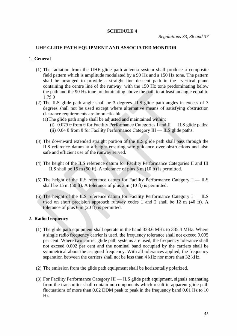
45
SCHEDULE 4
Regulations 33, 36 and 37
UHF GLIDE PATH EQUIPMENT AND ASSOCIATED MONITOR
1. General
(1) The radiation from the UHF glide path antenna system shall produce a composite
field pattern which is amplitude modulated by a 90 Hz and a 150 Hz tone. The pattern
shall be arranged to provide a straight line descent path in the vertical plane
containing the centre line of the runway, with the 150 Hz tone predominating below
the path and the 90 Hz tone predominating above the path to at least an angle equal to
1.75 θ
(2) The ILS glide path angle shall be 3 degrees. ILS glide path angles in excess of 3
degrees shall not be used except where alternative means of satisfying obstruction
clearance requirements are impracticable.
(a) The glide path angle shall be adjusted and maintained within:
(i) 0.075 θ from θ for Facility Performance Categories I and II — ILS glide paths;
(ii) 0.04 θ from θ for Facility Performance Category III — ILS glide paths.
(3) The downward extended straight portion of the ILS glide path shall pass through the
ILS reference datum at a height ensuring safe guidance over obstructions and also
safe and efficient use of the runway served.
(4) The height of the ILS reference datum for Facility Performance Categories II and III
— ILS shall be 15 m (50 ft). A tolerance of plus 3 m (10 ft) is permitted.
(5) The height of the ILS reference datum for Facility Performance Category I — ILS
shall be 15 m (50 ft). A tolerance of plus 3 m (10 ft) is permitted.
(6) The height of the ILS reference datum for Facility Performance Category I — ILS
used on short precision approach runway codes 1 and 2 shall be 12 m (40 ft). A
tolerance of plus 6 m (20 ft) is permitted.
2. Radio frequency
(1) The glide path equipment shall operate in the band 328.6 MHz to 335.4 MHz. Where
a single radio frequency carrier is used, the frequency tolerance shall not exceed 0.005
per cent. Where two carrier glide path systems are used, the frequency tolerance shall
not exceed 0.002 per cent and the nominal band occupied by the carriers shall be
symmetrical about the assigned frequency. With all tolerances applied, the frequency
separation between the carriers shall not be less than 4 kHz nor more than 32 kHz.
(2) The emission from the glide path equipment shall be horizontally polarized.
(3) For Facility Performance Category III — ILS glide path equipment, signals emanating
from the transmitter shall contain no components which result in apparent glide path
fluctuations of more than 0.02 DDM peak to peak in the frequency band 0.01 Hz to 10
Hz.

46
3. Coverage
(1) The glide path equipment shall provide signals sufficient to allow satisfactory
operation of a typical aircraft installation in sectors of 8 degrees in azimuth on each
side of the centre line of the ILS glide path, to a distance of at least18.5 km (10 NM)
up to 1.75 θ and down to 0.45 θ above the horizontal or to such lower angle, down to
0.30 θ, as required to safeguard the promulgated glide path intercept procedure.
(2) In order to provide the coverage for glide path performance specified in subparagraph
(1), the minimum field strength within this coverage sector shall be 400 microvolts
per metre (minus 95 dBW/m2). For Facility Performance Category I glide paths, this
field strength shall be provided down to a height of 30 m (100 ft) above the horizontal
plane containing the threshold. For Facility Performance Categories II and III glide
paths, this field strength shall be provided down to a height of 15 m (50 ft) above the
horizontal plane containing the threshold.
4. ILS glide path structure
(1) For Facility Performance Category I — ILS glide paths, bends in the glide path shall
not have amplitudes which exceed the following-
Zone Amplitude (DDM) (95% probability)
Outer limit of coverage
to ILS Point “C”
0.035
(2) For Facility Performance Categories II and III — ILS glide paths, bends in the glide
path shall not have amplitudes which exceed the following:
Zone Amplitude (DDM) (95% probability)
Outer limit of coverage
to ILS Point “A”
0.035
ILS Point “A” to“B” 0.035 at ILS Point “A” decreasing at a linear
rate to 0.023 at ILS Point ‘B’
ILS Point “B” to the ILS reference datum 0.023
5. Carrier modulation
(1) The nominal depth of modulation of the radio frequency carrier due to each of the 90
Hz and 150 Hz tones shall be 40 percent along the ILS glide path. The depth of
modulation shall not deviate outside the limits of 37.5 percent to 42.5 percent.
(2) The following tolerances shall be applied to the frequencies of the modulating tones-
(a) the modulating tones shall be 90 Hz and 150 Hz within 2.5 percent for Facility
Performance Category I — ILS;
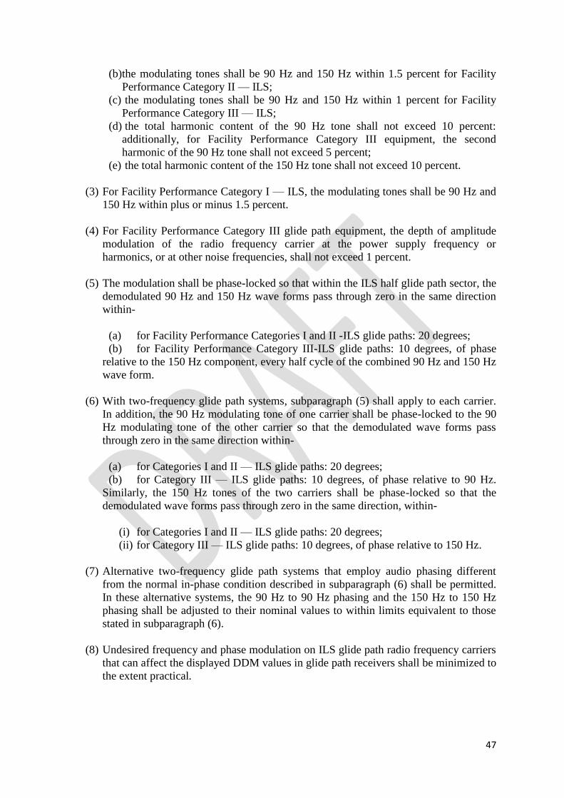
47
(b)the modulating tones shall be 90 Hz and 150 Hz within 1.5 percent for Facility
Performance Category II — ILS;
(c) the modulating tones shall be 90 Hz and 150 Hz within 1 percent for Facility
Performance Category III — ILS;
(d) the total harmonic content of the 90 Hz tone shall not exceed 10 percent:
additionally, for Facility Performance Category III equipment, the second
harmonic of the 90 Hz tone shall not exceed 5 percent;
(e) the total harmonic content of the 150 Hz tone shall not exceed 10 percent.
(3) For Facility Performance Category I — ILS, the modulating tones shall be 90 Hz and
150 Hz within plus or minus 1.5 percent.
(4) For Facility Performance Category III glide path equipment, the depth of amplitude
modulation of the radio frequency carrier at the power supply frequency or
harmonics, or at other noise frequencies, shall not exceed 1 percent.
(5) The modulation shall be phase-locked so that within the ILS half glide path sector, the
demodulated 90 Hz and 150 Hz wave forms pass through zero in the same direction
within-
(a) for Facility Performance Categories I and II -ILS glide paths: 20 degrees;
(b) for Facility Performance Category III-ILS glide paths: 10 degrees, of phase
relative to the 150 Hz component, every half cycle of the combined 90 Hz and 150 Hz
wave form.
(6) With two-frequency glide path systems, subparagraph (5) shall apply to each carrier.
In addition, the 90 Hz modulating tone of one carrier shall be phase-locked to the 90
Hz modulating tone of the other carrier so that the demodulated wave forms pass
through zero in the same direction within-
(a) for Categories I and II — ILS glide paths: 20 degrees;
(b) for Category III — ILS glide paths: 10 degrees, of phase relative to 90 Hz.
Similarly, the 150 Hz tones of the two carriers shall be phase-locked so that the
demodulated wave forms pass through zero in the same direction, within-
(i) for Categories I and II — ILS glide paths: 20 degrees;
(ii) for Category III — ILS glide paths: 10 degrees, of phase relative to 150 Hz.
(7) Alternative two-frequency glide path systems that employ audio phasing different
from the normal in-phase condition described in subparagraph (6) shall be permitted.
In these alternative systems, the 90 Hz to 90 Hz phasing and the 150 Hz to 150 Hz
phasing shall be adjusted to their nominal values to within limits equivalent to those
stated in subparagraph (6).
(8) Undesired frequency and phase modulation on ILS glide path radio frequency carriers
that can affect the displayed DDM values in glide path receivers shall be minimized to
the extent practical.

48
6. Displacement sensitivity
(1) For Facility Performance Category I-ILS glide paths, the nominal angular
displacement sensitivity shall correspond to a DDM of 0.0875 at angular
displacements above and below the glide path between 0.07 θ and 0.14 θ.
(2) For Facility Performance Category I-ILS glide paths, the nominal angular
displacement sensitivity shall correspond to a DDM of 0.0875 at an angular
displacement below the glide path of 0.12 θ with a tolerance of plus or minus 0.02 θ.
The upper and lower sectors shall be as symmetrical as practicable within the limits
specified in subparagraph (1).in 3.6.1.
(3) For Facility Performance Category II-ILS glide paths, the angular displacement
sensitivity shall be as symmetrical as practicable. The nominal angular displacement
sensitivity shall correspond to a DDM of 0.0875 at an angular displacement of-
(a) 0.12 θ below path with a tolerance of plus or minus 0.02 θ;
(b) 0.12 θ above path with a tolerance of plus 0.02 θ and minus 0.05 θ
(4) For Facility Performance Category III — ILS glide paths, the nominal angular
displacement sensitivity shall correspond to a DDM of 0.0875 at angular
displacements above and below the glide path of 0.12 θ with a tolerance of plus or
minus 0.02 θ.
(5) The DDM below the ILS glide path shall increase smoothly for decreasing angle until
a value of 0.22 DDM is reached. This value shall be achieved at an angle not less than
0.30 θ above the horizontal. However, if it is achieved at an angle above 0.45 θ, the
DDM value shall not be less than 0.22 at least down to 0.45 θ or to such lower angle,
down to 0.30 θ, as required to safeguard the promulgated glide path intercept
procedure.
(6) For Facility Performance Category I-ILS glide paths, the angular displacement
sensitivity shall be adjusted and maintained within plus or minus 25 percent of the
nominal value selected.
(7) For Facility Performance Category II-ILS glide paths, the angular displacement
sensitivity shall be adjusted and maintained within plus or minus 20 percent of the
nominal value selected.
(8) For Facility Performance Category III-ILS glide paths, the angular displacement
sensitivity shall be adjusted and maintained within plus or minus 15 percent of the
nominal value selected.
7. Monitoring
(1) The automatic monitor system shall provide a warning to the designated control
points and cause radiation to cease within the periods specified in subparagraph (3)(a)
if any of the following conditions persist-
(a) shift of the mean ILS glide path angle equivalent to more than minus 0.075 θ
to plus 0.10 θ from θ;

49
(b) in the case of ILS glide paths in which the basic functions are provided by the
use of a single-frequency system, a reduction of power output to less than 50 per cent
of normal, provided the glide path continues to meet the requirements of paragraph 3,
4 and 5;
(c) in the case of ILS glide paths in which the basic functions are provided by the
use of two-frequency systems, a reduction of power output for either carrier to less
than 80 per cent of normal, except that a greater reduction to between 80 per cent and
50 per cent of normal may be permitted, provided the glide path continues to meet the
requirements of paragraphs 3, 4 and 5;
(d) for Facility Performance Category I-ILS glide paths, a change of the angle
between the glide path and the line below the glide path (150 Hz predominating) at
which a DDM of 0.0875 is realized by more than the greater of:
(i) plus or minus 0.0375 θ; or
(ii) an angle equivalent to a change of displacement sensitivity to a value
differing by 25 per cent from the nominal value;
(e) for Facility Performance Categories II and III-ILS glide paths, a change of
displacement sensitivity to a value differing by more than 25 per cent from the
nominal value;
(f) lowering of the line beneath the ILS glide path at which a DDM of 0.0875 is
realized to less than 0.7475 θ from horizontal;
(g) a reduction of DDM to less than 0.175 within the specified coverage below
the glide path sector.
(2) Monitoring of the ILS glide path characteristics to smaller tolerances shall be
arranged in those cases where operational penalties would otherwise exist.
(3) The total period of radiation, including period(s) of zero radiation, outside the
performance limits specified in paragraph (1) shall be as short as practicable,
consistent with the need for avoiding interruptions of the navigation service provided
by the ILS glide path.
(a) The total period referred to under paragraph (2) shall not exceed under any
circumstances: 6 seconds for Category I-ILS glide paths; 2 seconds for
Categories II and III- ILS glide paths.
(b) The total period specified under subparagraph (a) for Categories II and III- ILS
glide paths shall not exceed 1 second.
(4) Design and operation of the monitor system shall be consistent with the requirement
that radiation shall cease and a warning shall be provided at the designated remote
control points in the event of failure of the monitor system itself.
8. Integrity and continuity of service requirements
(1) The probability of not radiating false guidance signals shall not be less than 1 – 0.5 ×
10–9 in any one landing for Facility Performance Categories II and III glide paths.

50
(2) The probability of not radiating false guidance signals shall not be less than 1 – 1.0 ×
10–7 in any one landing for Facility Performance Category I glide paths.
(3) The probability of not losing the radiated guidance signal shall be greater than 1 – 2 ×
10–6 in any period of 15 seconds for Facility Performance Categories II and III glide
paths (equivalent to 2 000 hours mean time between outages).
(4) The probability of not losing the radiated guidance signal shall exceed 1 – 4 × 10⁻⁶ in
any period of 15 seconds for Facility Performance Category I glide paths (equivalent
to 1 000 hours mean time between outages).
9. Localizer and glide path frequency pairing
(1)The pairing of the runway localizer and glide path transmitter frequencies of an
instrument landing system shall be taken from the following list-

51
(2)In regions where the requirements for runway localizer and glide path transmitter
frequencies of an instrument landing system do not justify more than 20 pairs, they
shall be selected sequentially, as required, from the following list-
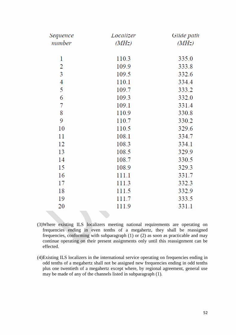
52
(3)Where existing ILS localizers meeting national requirements are operating on
frequencies ending in even tenths of a megahertz, they shall be reassigned
frequencies, conforming with subparagraph (1) or (2) as soon as practicable and may
continue operating on their present assignments only until this reassignment can be
effected.
(4)Existing ILS localizers in the international service operating on frequencies ending in
odd tenths of a megahertz shall not be assigned new frequencies ending in odd tenths
plus one twentieth of a megahertz except where, by regional agreement, general use
may be made of any of the channels listed in subparagraph (1).

53
SCHEDULE 5
Regulation 39
SPECIFICATION FOR VHF OMNI DIRECTIONAL RANGE (VOR)
1. General
(1)The VOR shall be constructed and adjusted so that similar instrumental indications in
aircraft represent equal clockwise angular deviations (bearings), degree for degree
from magnetic North as measured from the location of the VOR.
(2)The VOR shall radiate a radio frequency carrier with which are associated two
separate 30 Hz modulations. One of these modulations shall be such that its phase is
independent of the azimuth of the point of observation (reference phase). The other
modulation (variable phase) shall be such that its phase at the point of observation
differs from that of the reference phase by an angle equal to the bearing of the point of
observation with respect to the VOR.
(3)The reference and variable phase modulations shall be in phase along the reference
magnetic meridian through the station.
2. Radio frequency
(1)The VOR shall operate in the band 111.975 MHz to 117.975 MHz except that
frequencies in the band 108 MHz to 111.975 MHz may be used when, in accordance
with the provisions of Radio Frequency Spectrum Utilization Regulations, the use of
such frequencies is acceptable. The highest assignable frequency shall be 117.950
MHz. The channel separation shall be in increments of 50 kHz referred to the highest
assignable frequency. In areas where 100 kHz or 200 kHz channel spacing is in
general use, the frequency tolerance of the radio frequency carrier shall be plus or
minus 0.005 percent.
(2)The frequency tolerance of the radio frequency carrier of all new installations
implemented after 23 May 1974 in areas where 50 kHz channel spacing is in use shall
be plus or minus 0.002 percent.
(3)In areas where new VOR installations are implemented and are assigned frequencies
spaced at 50 kHz from existing VORs in the same area, priority shall be given to
ensuring that the frequency tolerance of the radio frequency carrier of the existing
VORs is reduced to plus or minus 0.002 percent.
3. Polarization and pattern accuracy
(1)The emission from the VOR shall be horizontally polarized. The vertically polarized
component of the radiation shall be as small as possible.
(2)The ground station contribution to the error in the bearing information conveyed by
the horizontally polarized radiation from the VOR for all elevation angles between 0
and 40 degrees, measured from the centre of the VOR antenna system, shall be within
plus or minus 2 degrees.
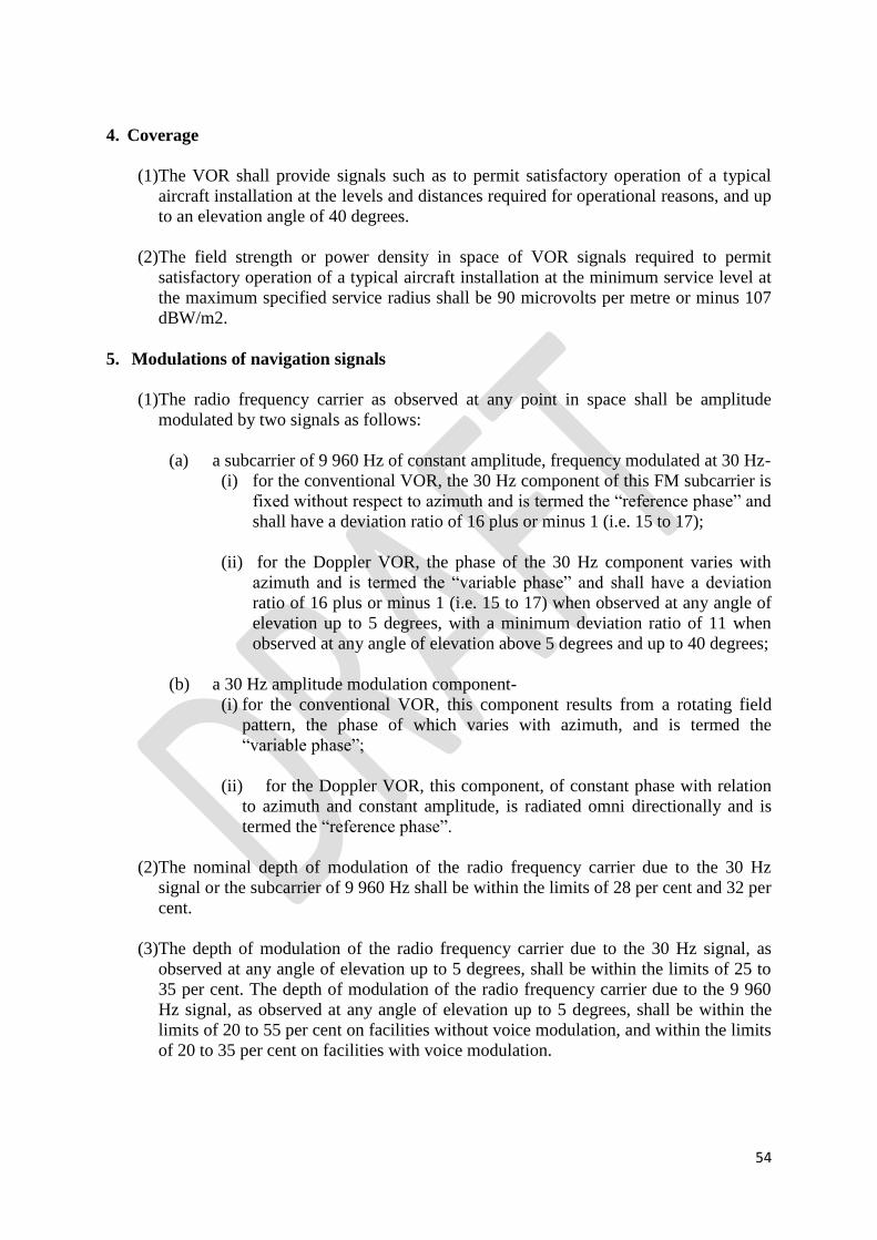
54
4. Coverage
(1)The VOR shall provide signals such as to permit satisfactory operation of a typical
aircraft installation at the levels and distances required for operational reasons, and up
to an elevation angle of 40 degrees.
(2)The field strength or power density in space of VOR signals required to permit
satisfactory operation of a typical aircraft installation at the minimum service level at
the maximum specified service radius shall be 90 microvolts per metre or minus 107
dBW/m2.
5. Modulations of navigation signals
(1)The radio frequency carrier as observed at any point in space shall be amplitude
modulated by two signals as follows:
(a) a subcarrier of 9 960 Hz of constant amplitude, frequency modulated at 30 Hz-
(i) for the conventional VOR, the 30 Hz component of this FM subcarrier is
fixed without respect to azimuth and is termed the “reference phase” and
shall have a deviation ratio of 16 plus or minus 1 (i.e. 15 to 17);
(ii) for the Doppler VOR, the phase of the 30 Hz component varies with
azimuth and is termed the “variable phase” and shall have a deviation
ratio of 16 plus or minus 1 (i.e. 15 to 17) when observed at any angle of
elevation up to 5 degrees, with a minimum deviation ratio of 11 when
observed at any angle of elevation above 5 degrees and up to 40 degrees;
(b) a 30 Hz amplitude modulation component-
(i) for the conventional VOR, this component results from a rotating field
pattern, the phase of which varies with azimuth, and is termed the
“variable phase”;
(ii) for the Doppler VOR, this component, of constant phase with relation
to azimuth and constant amplitude, is radiated omni directionally and is
termed the “reference phase”.
(2)The nominal depth of modulation of the radio frequency carrier due to the 30 Hz
signal or the subcarrier of 9 960 Hz shall be within the limits of 28 per cent and 32 per
cent.
(3)The depth of modulation of the radio frequency carrier due to the 30 Hz signal, as
observed at any angle of elevation up to 5 degrees, shall be within the limits of 25 to
35 per cent. The depth of modulation of the radio frequency carrier due to the 9 960
Hz signal, as observed at any angle of elevation up to 5 degrees, shall be within the
limits of 20 to 55 per cent on facilities without voice modulation, and within the limits
of 20 to 35 per cent on facilities with voice modulation.

55
(4)The variable and reference phase modulation frequencies shall be 30 Hz within plus
or minus 1 percent.
(5)The subcarrier modulation mid-frequency shall be 9 960 Hz within plus or minus 1
percent.
(6) For the conventional VOR, the percentage of amplitude modulation of the 9 960 Hz
subcarrier shall not exceed 5 percent and for the Doppler VOR, the percentage of
amplitude modulation of the 9 960 Hz subcarrier shall not exceed 40 percent when
measured at a point at least 300 m (1 000 ft) from the VOR.
(7)Where 50 kHz VOR channel spacing is implemented, the sideband level of the
harmonics of the 9 960 Hz component in the radiated signal shall not exceed the
following levels referred to the level of the 9 960 Hz sideband-
6. Voice and identification
(1) If the VOR provides a simultaneous communication channel ground-to-air, it shall be
on the same radio frequency carrier as used for the navigational function. The radiation
on this channel shall be horizontally polarized.
(2) The peak modulation depth of the carrier on the communication channel shall not be
greater than 30 per cent.
(3) The audio frequency characteristics of the speech channel shall be within 3 dB
relative to the level at 1 000 Hz over the range 300 Hz to 3 000 Hz.
(4) The VOR shall provide for the simultaneous transmission of a signal of identification
on the same radio frequency carrier as that used for the navigational function. The
identification signal radiation shall be horizontally polarized.
(5) The identification signal shall employ the International Morse Code and consist of
two or three letters. It shall be sent at a speed corresponding to approximately 7 words
per minute. The signal shall be repeated at least once every 30 seconds and the
modulation tone shall be 1 020 Hz within plus or minus 50 Hz : the identification signal
shall be transmitted at least three times each 30 seconds, spaced equally within that
time period. One of these identification signals will take the form of a voice
identification.
(6) The depth to which the radio frequency carrier is modulated by the code identification
signal shall be close to, but not in excess of 10 per cent except that, where a
communication channel is not provided, it shall be permissible to increase the
modulation by the code identification signal to a value not exceeding 20 per cent.

56
(a) If the VOR provides a simultaneous communication channel ground-to-air, the
modulation depth of the code identification signal shall be 5 plus or minus 1 per
cent in order to provide a satisfactory voice quality.
(7) The transmission of speech shall not interfere in any way with the basic navigational
function. When speech is being radiated, the code identification shall not be suppressed.
(8) The VOR receiving function shall permit positive identification of the wanted signal
under the signal conditions encountered within the specified coverage limits, and with
the modulation parameters specified at subparagraphs (5) and (6).
7. Monitoring
(1)Suitable equipment located in the radiation field shall provide signals for the
operation of an automatic monitor. The monitor shall transmit a warning to a control
point, and either remove the identification and navigation components from the carrier
or cause radiation to cease if any one or a combination of the following deviations
from established conditions arises:
(a) a change in excess of 1 degree at the monitor site of the bearing information
transmitted by the VOR;
(b) a reduction of 15 per cent in the modulation components of the radio
frequency signals voltage level at the monitor of either the subcarrier, or 30 Hz
amplitude modulation signals, or both.
(2) Failure of the monitor itself shall transmit a warning to a control point and either:
(a) remove the identification and navigation components from the carrier; or
(b) cause radiation to cease.
8. Interference immunity performance for VOR receiving systems
(1)The VOR receiving system shall provide adequate immunity to interference from two
signal, third-order intermodulation products caused by VHF FM broadcast signals
having levels in accordance with the following:
for VHF FM sound broadcasting signals below 107.7 MHz,
where the frequencies of the two VHF FM sound broadcasting signals produce, within the
receiver, a two signal, third-order inter modulation product on the desired VOR frequency.

57
N1 and N2 are the levels (dBm) of the two VHF FM sound broadcasting signals at the VOR
receiver input. Neither level shall exceed the desensitization criteria set forth in subparagraph
2.
Δf = 108.1 – f1, where f1 is the frequency of N1, the VHF FM sound broadcasting signal
closer to 108.1 MHz.
(2)The VOR receiving system shall not be desensitized in the presence of VHF FM
broadcast signals having levels in accordance with the following table:

58
SCHEDULE 6
Regulation 40
SPECIFICATION FOR NON-DIRECTIONAL RADIO BEACON (NDB)
1. Coverage
(1) The minimum value of field strength in the rated coverage of an NDB shall be
70°microvolts per metre.
(2) All notifications or promulgations of NDBs shall be based upon the average radius of the
rated coverage.
(3) Where the rated coverage of an NDB is materially different in various operationally
significant sectors, its classification shall be expressed in terms of the average radius of
rated coverage and the angular limits of each sector as radius of coverage of
sector/angular limits of sector expressed as magnetic bearing clockwise from the beacon
and where it is desirable to classify an NDB in such a manner, the number of sectors
shall be kept to a minimum and preferably shall not exceed two.
2. Limitations in radiated power
The power radiated from an NDB shall not exceed by more than 2 dB that necessary to
achieve its agreed rated coverage, except that this power may be increased if coordinated
regionally or if no harmful interference to other facilities will result.
3. Radio frequencies
(1) The radio frequencies assigned to NDBs shall be selected from those available in
that portion of the spectrum between 190 kHz and 1 750 kHz.
(2) The frequency tolerance applicable to NDBs shall be 0.01 per cent except that, for
NDBs of antenna power above 200 W using frequencies of 1 606.5 kHz and above,
the tolerance shall be 0.005 per cent.
(3) Where two locators are used as supplements to an ILS, the frequency separation
between the carriers of the two shall be not less than 15 kHz to ensure correct
operation of the radio compass, and preferably not more than 25 kHz in order to
permit a quick tuning shift in cases where an aircraft has only one radio compass.
(4) Where locators associated with ILS facilities serving opposite ends of a single
runway are assigned a common frequency, provision shall be made to ensure that the
facility not in operational use cannot radiate.
4. Identification
(1) Each NDB shall be individually identified by a two- or three-letter International Morse
Code group transmitted at a rate corresponding to approximately 7 words per minute.

59
(2) The complete identification shall be transmitted at least once every 30 seconds, except
where the beacon identification is effected by on/off keying of the carrier. In this latter
case, the identification shall be at approximately 1-minute intervals, except that a shorter
interval may be used at particular NDB stations where this is found to be operationally
desirable.
(3) Except for those cases where the beacon identification is effected by on/off keying of the
carrier, the identification signal shall be transmitted at least three times each 30 seconds,
spaced equally within that time period.
(4) For NDBs with an average radius of rated coverage of 92.7 km (50 NM) or less that are
primarily approach and holding aids in the vicinity of an aerodrome, the identification
shall be transmitted at least three times each 30 seconds, spaced equally within that time
period.
(5) The frequency of the modulating tone used for identification shall be 1 020 Hz plus or
minus 50 Hz or 400 Hz plus or minus 25 Hz.
5. Characteristics of emissions
(1) Except as provided in subparagraph (2) 3.4.6.1.1, all NDBs shall radiate an
uninterrupted carrier and be identified by on/off keying of an amplitude modulating
tone (NON/A2A).
(2) NDBs other than those wholly or partly serving as holding, approach and landing aids,
or those having an average radius of rated coverage of less than 92.7 km (50 NM), may
be identified by on/off keying of the unmodulated carrier (NON/A1A) if they are in
areas of high beacon density or where the required rated coverage is not practicable of
achievement because of-
(a) radio interference from radio stations;
(b) high atmospheric noise; or
(c) local conditions.
(3) For each NDB identified by on/off keying of an audio modulating tone, the depth of
modulation shall be maintained as near to 95 per cent as practicable.
(4) For each NDB identified by on/off keying of an audio modulating tone, the
characteristics of emission during identification shall be such as to ensure satisfactory
identification at the limit of its rated coverage.
(5) The carrier power of an NDB with NON/A2A emissions shall not fall when the
identity signal is being radiated except that, in the case of an NDB having an average
radius of rated coverage exceeding 92.7 km (50 NM), a fall of not more than 1.5 dB
will be accepted.
(6) Unwanted audio frequency modulations shall total less than 5 percent of the amplitude
of the carrier.

60
(7) The bandwidth of emissions and the level of spurious emissions shall be kept at the
lowest value that the state of technique and the nature of the service permit.
6. Siting of locators
(1)Where locators are used as a supplement to the ILS, they shall be located at the sites
of the outer and middle marker beacons. Where only one locator is used as a
supplement to the ILS, preference shall be given to location at the site of the outer
marker beacon. Where locators are employed as an aid to final approach in the
absence of an ILS, equivalent locations to those applying when an ILS is installed
shall be selected, taking into account the relevant obstacle clearance provisions of the
Civil Aviation (Construction of Visual and Instrument Flight Procedures) Regulations
2016.
(2)Where locators are installed at both the middle and outer marker positions, they shall
be located, where practicable, on the same side of the extended centre line of the
runway in order to provide a track between the locators which will be more nearly
parallel to the centre line of the runway.
7. Monitoring
(1) For each NDB, suitable means shall be provided to enable detection of any of the
following conditions at an appropriate location-
(a) a decrease in radiated carrier power of more than 50 per cent below that required
for the rated coverage;
(b) failure to transmit the identification signal;
(c) malfunctioning or failure of the means of monitoring itself.
(2) When an NDB is operated from a power source having a frequency which is close to
airborne ADF equipment switching frequencies, and where the design of the NDB is
such that the power supply frequency is likely to appear as a modulation product on
the emission, the means of monitoring shall be capable of detecting such power
supply modulation on the carrier in excess of 5 per cent.
(3) During the hours of service of a locator, the means of monitoring shall provide for a
continuous check on the functioning of the locator as prescribed in subparagraph (1).
(4) During the hours of service of an NDB other than a locator, the means of monitoring
shall provide for a continuous check on the functioning of the NDB as prescribed in
in subparagraph (1).

61
SCHEDULE 7
Regulation 43
SPECIFICATION FOR UHF DISTANCE MEASURING EQUIPMENT (DME)
1. General
(1) The DME system shall provide for continuous and accurate indication in the cockpit of
the slant range distance of an equipped aircraft from an equipped ground reference
point.
(2) The system shall comprise two basic components, one fitted in the aircraft, the other
installed on the ground. The aircraft component shall be referred to as the interrogator
and the ground component as the transponder.
(3) In operation, interrogators shall interrogate transponders which shall, in turn, transmit
to the interrogator replies synchronized with the interrogations, thus providing means
for accurate measurement of distance.
(4) DME/P shall have two operating modes, IA and FA.
(5) When a DME is associated with an ILS, MLS or VOR for the purpose of constituting a
single facility, they shall-0000000
(a) be operated on a standard frequency pairing in accordance with paragraph 2(3)(d);
(b) be collocated within the limits prescribed for associated facilities in subparagraph
(6); and
(c) comply with the identification provisions of paragraph 2(6)
(6) Collocation limits for a DME facility associated with an ILS, MLS or VOR facility
(a) Associated VOR and DME facilities shall be collocated in accordance with the
following-
(i) for those facilities used in terminal areas for approach purposes or other
procedures where the highest position fixing accuracy of system capability
is required, the separation of the VOR and DME antennas does not exceed
80 m (260 ft);
(ii) for purposes other than those indicated in a), the separation of the VOR
and DME antennas does not exceed 600 m (2 000 ft).
(b) Use of DME or other standard radio navigation aids as an alternative to ILS
marker beacons-
(i) when DME is used as an alternative to ILS marker beacons, the DME
shall be located on the airport so that the zero range indication is a point
near the runway. If the DME associated with ILS uses a zero range offset,
this facility has to be excluded from RNAV solutions-
(aa) in order to reduce the triangulation error, the DME shall be sited to
ensure a small angle (e.g. less than 20degrees) between the approach

62
path and the direction to the DME at the points where the distance
information is required;
(bb) the use of DME as an alternative to the middle marker beacon assumes
a DME system accuracy of 0.37 km (0.2 NM) or better and a resolution
of the airborne indication to allow this accuracy to be attained;
(cc) while it is not specifically required that DME be frequency paired with
the localizer when it is used as an alternative for the outer marker,
frequency pairing is preferred wherever DME is used with ILS to
simplify pilot operation and to enable aircraft with two ILS receivers to
use both receivers on the ILS channel;
(dd) When the DME is frequency paired with the localizer, the DME
transponder identification should be obtained by the “associated” signal
from the frequency-paired localizer;
(ii) in some locations, the Competent Authority may authorize the use of
other means to provide fixes, such as NDB, VOR or GNSS. This may
be useful in particular in locations where aircraft user equipage with
DME is low, or if the DME is out of service.
(7) The standards in paragraph 2, 3, and 4 denoted by ‡ shall apply only to DME
equipment first installed after 1 January 1989.
2. System characteristics
(1) Performance
(a) The system shall provide a means of measurement of slant range distance from an
aircraft to a selected transponder to the limit of coverage prescribed by the
operational requirements for the selected transponder.
(b) Coverage
(i) When associated with a VOR, DME/N coverage shall be at least that of the
VOR to the extent practicable.
(ii) When associated with either an ILS or an MLS, DME/N coverage shall be at
least that of the respective ILS or of the MLS azimuth angle guidance
coverage sectors.
(iii)DME/P coverage shall be at least that provided by the MLS azimuth angle
guidance coverage sectors.
(c) Accuracy
(i) System accuracy. The accuracy standards specified in subparagraph (1) (d)
paragraph 3(5) and paragraph 4 (3) (f) shall be met on a 95 per cent
probability basis.

63
(d) DME/P accuracy
(i) Error components. The path following error (PFE) shall be comprised of those
frequency components of the DME/P error at the output of the interrogator
which lie below 1.5 rad/s. The control motion noise (CMN) shall be
comprised of those frequency components of the DME/P error at the output of
the interrogator which lie between 0.5 rad/s and 10 rad/s.
(ii) Errors on the extended runway centre line shall not exceed the values given in
Table B at the end of this chapter.
(iii) In the approach sector, away from the extended runway centre line, the
allowable PFE for both standard 1 and standard 2 shall be permitted to
increase linearly with angle up to plus or minus 40 degrees MLS azimuth
angle where the permitted error is 1.5 times that on the extended runway
centre line at the same distance. The allowable CMN shall not increase with
angle. There shall be no degradation of either PFE or CMN with elevation
angle.
(2) Radio frequencies and polarization. The system shall operate with vertical polarization
in the frequency band 960 MHz to 1 215 MHz. The interrogation and reply frequencies
shall be assigned with 1MHz spacing between channels.
(3) Channelling
(a) DME operating channels shall be formed by pairing interrogation and reply
frequencies and by pulse coding on the paired frequencies.
(b) Pulse coding. DME/P channels shall have two different interrogation pulse codes
as shown in Table 7-1. One shall be used in the initial approach (IA) mode; the
other shall be used in the final approach (FA) mode.
(c) DME operating channels shall be chosen from Table 7-2 of 352 channels in which
the channel numbers, frequencies, and pulse codes are assigned.
(d) Channel pairing. When a DME transponder is intended to operate in association
with a single VHF navigation facility in the 108 MHz to 117.95 MHz frequency
band and/or an MLS angle facility in the 5 031.0 MHz to 5 090.7 MHz frequency
band, the DME operating channel shall be paired with the VHF channel and/or
MLS angle frequency as given in Table 7-2.
(4) Interrogation pulse repetition frequency.
(a) DME/N. The interrogator average pulse repetition frequency (PRF) shall not
exceed 30 pairs of pulses per second, based on the assumption that at least 95 per
cent of the time is occupied for tracking.
(b) DME/N. If it is desired to decrease the time of search, the PRF may be increased
during search but shall not exceed 150 pairs of pulses per second.
(c) DME/N. After 15 000 pairs of pulses have been transmitted without acquiring
indication of distance, the PRF shall not exceed 60 pairs of pulses per second
thereafter, until a change in operating channel is made or successful search is
completed.

64
(d) DME/N.When, after a time period of 30 seconds, tracking has not been established,
the pulse pair repetition frequency shall not exceed 30 pulse pairs per second
thereafter.
(e) DME/P. The interrogator pulse repetition frequency shall not exceed the following
number of pulse pairs per second:
(i) Search 40
(ii) aircraft on the ground 5
(iii) initial approach mode track 16
(iv) final approach mode track 40
(5) Aircraft handling capacity of the system
(a) The aircraft handling capacity of transponders in an area shall be adequate for the
peak traffic of the area or 100 aircraft, whichever is the lesser.
(b)Where the peak traffic in an area exceeds 100 aircraft, the transponder shall be
capable of handling that peak traffic.
(6) Transponder identification
(a) All transponders shall transmit an identification signal in one of the following
forms as required by paragraph 2(6) (e).
(i) an “independent” identification consisting of coded (International
Morse Code) identity pulses which can be used with all transponders;
(ii) an “associated” signal which can be used for transponders specifically
associated with a VHF navigation or an MLS angle guidance facility
which itself transmits an identification signal.
(b) Both systems of identification shall use signals, which shall consist of the
transmission for an appropriate period of a series of paired pulses transmitted at a
repetition rate of 1 350 pulse pairs per second, and shall temporarily replace all
reply pulses that would normally occur at that time except as in paragraph 2 (6)
(b) (ii). These pulses shall have similar characteristics to the other pulses of the
reply signals.
(i) DME/N. Reply pulses shall be transmitted between key down times.
(ii) DME/N. If it is desired to preserve a constant duty cycle, an equalizing
pair of pulses, having the same characteristics as the identification
pulse pairs, shall be transmitted 100 microseconds plus or minus 10
microseconds after each identity pair.
(iii) DME/P. Reply pulses shall be transmitted between key down times.
(iv) For the DME/P transponder, reply pulse pairs to valid FA mode
interrogations shall also be transmitted during key down times and
have priority over identification pulse pairs.
(v) The DME/P transponder shall not employ the equalizing pair of pulses
of subparagraph (ii).

65
(c) The characteristics of the “independent” identification signal shall be as follows-
(i) the identity signal shall consist of the transmission of the beacon code in the
form of dots and dashes (International Morse Code) of identity pulses at
least once every 40 seconds, at a rate of at least 6 words per minute; and
(ii) the identification code characteristic and letter rate for the DME
transponder shall conform to the following to ensure that the maximum
total key down time does not exceed 5 seconds per identification code
group. The dots shall be a time duration of 0.1 second to 0.160 second.
The dashes shall be typically 3 times the duration of the dots.
The duration between dots or dashes shall be equal to that of one dot plus
or minus 10 per cent. The time duration between letters or numerals shall
not be less than three dots. The total period for transmission of an
identification code group shall not exceed 10 seconds.
(d) The characteristics of the “associated” signal shall be as follows-
(i) when associated with a VHF or an MLS angle facility, the identification
shall be transmitted in the form of dots and dashes (International Morse
Code) and shall be synchronized with the VHF facility identification code;
(ii) each 40-second interval shall be divided into four or more equal periods,
with the transponder identification transmitted during one period only and
the associated VHF and MLS angle facility identification, where these are
provided, transmitted during the remaining periods;
(iii) for a DME transponder associated with an MLS, the identification shall be
the last three letters of the MLS angle facility identification.
(e) Identification implementation
(i) The “independent” identification code shall be employed wherever a
transponder is not specifically associated with a VHF navigational facility or an
MLS facility.
(ii) Wherever a transponder is specifically associated with a VHF
navigational facility or an MLS facility, identification shall be provided by the
“associated” code.
(iii) When voice communications are being radiated on an associated VHF
navigational facility, an “associated” signal from the transponder shall not be
suppressed.
(7) DME/P mode transition
(a) The DME/P interrogator for standard 1 accuracy shall change from IA mode
track to FA mode track at 13 km (7 NM) from the transponder when
approaching the transponder, or any other situation when within 13 km (7 NM)

66
(b) For standard 1 accuracy, the transition from IA mode to FA mode track
operation may be initiated within 14.8 m (8 NM) from the transponder.
Outside 14.8 km (8 NM), the interrogator shall not interrogate in the FA mode.
(8) System efficiency. The DME/P system accuracy of paragraph 2 (1) (d) shall be achieved
with a system efficiency of 50 per cent or more.
3. Detailed technical characteristics of transponder and associated monitor
(1) Transmitter
(a) Frequency of operation. The transponder shall transmit on the reply frequency
appropriate to the assigned DME channel.
(b)Frequency stability. The radio frequency of operation shall not vary more than
plus or minus 0.002 per cent from the assigned frequency.
(c) Pulse shape and spectrum. The following shall apply to all radiated pulses:
(i) Pulse rise time.
(aa) DME/N. Pulse rise time shall not exceed 3 microseconds.
(bb) DME/P. Pulse rise time shall not exceed 1.6 microseconds. For the FA
mode, the pulse shall have a partial rise time of 0.25 plus or minus 0.05
microsecond. With respect to the FA mode and accuracy standard 1,
the slope of the pulse in the partial rise time shall not vary by more than
plus or minus 20 per cent. For accuracy standard 2, the slope shall not
vary by more than plus or minus 10 per cent.
(ii) Pulse duration shall be 3.5 microseconds plus or minus 0.5
microsecond.
(iii) Pulse decay time shall nominally be 2.5 microseconds but shall not
exceed 3.5 microseconds.
(iv) The instantaneous amplitude of the pulse shall not, at any instant
between the point of the leading edge which is 95 per cent of maximum
amplitude and the point of the trailing edge which is 95 per cent of the
maximum amplitude, fall below a value which is 95 per cent of the maximum
voltage amplitude of the pulse.
(v) For DME/N and DME/P: the spectrum of the pulse modulated signal shall
be such that during the pulse the EIRP contained in a 0.5 MHz band centred
on frequencies 0.8 MHz above and 0.8 MHz below the nominal channel
frequency in each case shall not exceed 200 mW, and the EIRP contained in
a 0.5 MHz band centred on frequencies 2 MHz above and 2 MHz below the
nominal channel frequency in each case shall not exceed 2 mW. The EIRP
contained within any 0.5 MHz band shall decrease monotonically as the band
centre frequency moves away from the nominal channel frequency.

67
(vi) To ensure proper operation of the thresholding techniques, the
instantaneous magnitude of any pulse turn-on transients which occur in time
prior to the virtual origin shall be less than one per cent of the pulse peak
amplitude. Initiation of the turn-on process shall not commence sooner than 1
microsecond prior to the virtual origin.
(d) Pulse spacing
(i) The spacing of the constituent pulses of transmitted pulse pairs shall be as
given in the table in subparagraph 3 (4) (a).
(ii) DME/N. The tolerance on the pulse spacing shall be plus or minus 0.25
microsecond.
(iii) DME/N. The tolerance on the DME/N pulse spacing shall be plus or
minus 0.10 microsecond.
(iv) DME/P. The tolerance on the pulse spacing shall be plus or minus 0.10
microsecond.
(v) The pulse spacings shall be measured between the half voltage points on
the leading edges of the pulses.
(e) Peak power output
(i) DME/N. The peak EIRP shall not be less than that required to ensure a peak
pulse power density of approximately minus 83 dBW/m2 at the maximum
specified service range and level.
(ii) DME/N. The peak equivalent isotropically radiated power shall not be less
than that required to ensure a peak pulse power density of minus 89
dBW/m2 under all operational weather conditions at any point within
coverage specified in paragraph 2(1) (b).
(iii) DME/P. The peak equivalent isotropically radiated power shall not be less
than that required to ensure the following peak pulse power densities under
all operational weather conditions:
(aa) minus 89 dBW/m2 at any point within the coverage specified in
paragraph 2(1) (b) at ranges greater than 13 km (7 NM) from the
transponder antenna;
(bb) minus 75 dBW/m2 at any point within the coverage specified in
paragraph 2(1) (b) at ranges less than 13 km (7 NM) from the
transponder antenna;
(cc) minus 70 dBW/m2 at the MLS approach reference datum;
(dd) minus 79 dBW/m2 at 2.5 m (8 ft) above the runway surface, at the
MLS datum point, or at the farthest point on the runway centre line
which is in line of sight of the DME transponder antenna.
(iv) The peak power of the constituent pulses of any pair of pulses shall not
differ by more than 1 dB.
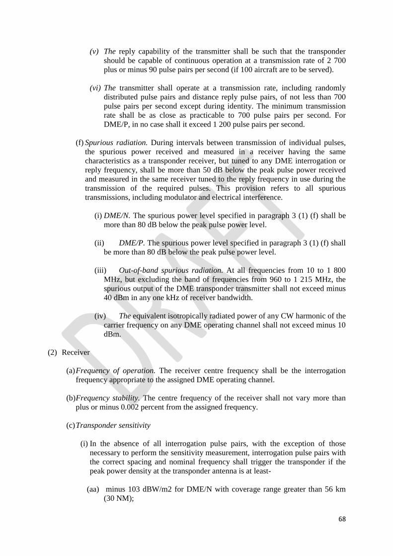
68
(v) The reply capability of the transmitter shall be such that the transponder
should be capable of continuous operation at a transmission rate of 2 700
plus or minus 90 pulse pairs per second (if 100 aircraft are to be served).
(vi) The transmitter shall operate at a transmission rate, including randomly
distributed pulse pairs and distance reply pulse pairs, of not less than 700
pulse pairs per second except during identity. The minimum transmission
rate shall be as close as practicable to 700 pulse pairs per second. For
DME/P, in no case shall it exceed 1 200 pulse pairs per second.
(f) Spurious radiation. During intervals between transmission of individual pulses,
the spurious power received and measured in a receiver having the same
characteristics as a transponder receiver, but tuned to any DME interrogation or
reply frequency, shall be more than 50 dB below the peak pulse power received
and measured in the same receiver tuned to the reply frequency in use during the
transmission of the required pulses. This provision refers to all spurious
transmissions, including modulator and electrical interference.
(i) DME/N. The spurious power level specified in paragraph 3 (1) (f) shall be
more than 80 dB below the peak pulse power level.
(ii) DME/P. The spurious power level specified in paragraph 3 (1) (f) shall
be more than 80 dB below the peak pulse power level.
(iii) Out-of-band spurious radiation. At all frequencies from 10 to 1 800
MHz, but excluding the band of frequencies from 960 to 1 215 MHz, the
spurious output of the DME transponder transmitter shall not exceed minus
40 dBm in any one kHz of receiver bandwidth.
(iv) The equivalent isotropically radiated power of any CW harmonic of the
carrier frequency on any DME operating channel shall not exceed minus 10
dBm.
(2) Receiver
(a) Frequency of operation. The receiver centre frequency shall be the interrogation
frequency appropriate to the assigned DME operating channel.
(b) Frequency stability. The centre frequency of the receiver shall not vary more than
plus or minus 0.002 percent from the assigned frequency.
(c) Transponder sensitivity
(i) In the absence of all interrogation pulse pairs, with the exception of those
necessary to perform the sensitivity measurement, interrogation pulse pairs with
the correct spacing and nominal frequency shall trigger the transponder if the
peak power density at the transponder antenna is at least-
(aa) minus 103 dBW/m2 for DME/N with coverage range greater than 56 km
(30 NM);

69
(bb) minus 93 dBW/m2 for DME/N with coverage range not greater than 56 km
(30 NM);
(cc) minus 86 dBW/m2 for DME/P IA mode;
(dd) minus 75 dBW/m2 for DME/P FA mode.
(ii) The minimum power densities specified in subparagraph (i) shall cause the
transponder to reply with an efficiency of at least-
(aa) 70 per cent for DME/N;
(bb) 70 per cent for DME/P IA mode;
(cc) 80 per cent for DME/P FA mode.
(iii) DME/N dynamic range. The performance of the transponder shall be
maintained when the power density of the interrogation signal at the transponder
antenna has any value between the minimum specified in subparagraph (i) up to
a maximum of minus 22 dBW/m2 when installed with ILS or MLS and minus
35 dBW/m2 when installed for other applications.
(iv) DME/P dynamic range. The performance of the transponder shall be
maintained when the power density of the interrogation signal at the transponder
antenna has any value between the minimum specified in subparagraph (i) up to
a maximum of minus 22 dBW/m2.
(v) The transponder sensitivity level shall not vary by more than 1 dB for
transponder loadings between 0 and 90 per cent of its maximum transmission
rate.
(vi) DME/N. When the spacing of an interrogator pulse pair varies from the
nominal value by up to plus or minus 1 microsecond, the receiver sensitivity
shall not be reduced by more than 1 dB.
(vii) DME/P. When the spacing of an interrogator pulse pair varies from the
nominal value by up to plus or minus 1 microsecond, the receiver sensitivity
shall not be reduced by more than 1 dB.
(d) Load limiting
(i) DME/N. When transponder loading exceeds 90 per cent of the maximum
transmission rate, the receiver sensitivity shall be automatically reduced in order
to limit the transponder replies, so as to ensure that the maximum permissible
transmission rate is not exceeded. (The available range of sensitivity reduction
shall be at least 50 dB.)
(ii) DME/P. To prevent transponder overloading the transponder shall
automatically limit its replies, so as to ensure that the maximum transmission
rate is not exceeded. If the receiver sensitivity reduction is implemented to meet
this requirement, it shall be applied to the IA mode only and shall not affect the
FA mode.
(e) Noise. When the receiver is interrogated at the power densities specified in
subparagraph (i) to produce a transmission rate equal to 90 per cent of the

70
maximum, the noise generated pulse pairs shall not exceed 5 percent of the
maximum transmission rate.
(f) Bandwidth
(i) The minimum permissible bandwidth of the receiver shall be such that the
transponder sensitivity level shall not deteriorate by more than 3 dB when the
total receiver drift is added to an incoming interrogation frequency drift of plus
or minus 100 kHz.
(ii) DME/N. The receiver bandwidth shall be sufficient to allow compliance with
paragraph 2(1)(c) when the input signals are those specified in paragraph 4(1)(c)
(iii) DME/P — IA mode. The receiver bandwidth shall be sufficient to allow
compliance with paragraph 2(1)(c) when the input signals are those specified in
paragraph 4(1)(c) The 12 dB bandwidth shall not exceed 2 MHz and the 60 dB
bandwidth shall not exceed 10 MHz.
(iv) DME/P — FA mode. The receiver bandwidth shall be sufficient to allow
compliance with paragraph 4(1) (c) when the input signals are those specified in
paragraph 4(1) (c). The 12 dB bandwidth shall not exceed 6 MHz and the 60 dB
bandwidth shall not exceed 20 MHz.
(v) Signals greater than 900 kHz removed from the desired channel nominal
frequency and having power densities up to the values specified in paragraph 3
(2) (c) (iii) in 7.3.2.3.3 for DME/N and paragraph 3 (2) (c) (iv) 7.3.2.3.4 for
DME/P shall not trigger the transponder. Signals arriving at the intermediate
frequency shall be suppressed at least 80 dB. All other spurious response or
signals within the 960 MHz to 1 215 MHz band and image frequencies shall be
suppressed at least 75 dB.
(g) Recovery time. Within 8 microseconds of the reception of a signal between 0 dB
and 60 dB above minimum sensitivity level, the minimum sensitivity level of the
transponder to a desired signal shall be within 3 dB of the value obtained in the
absence of signals. This requirement shall be met with echo suppression circuits, if
any, rendered inoperative. The 8 microseconds are to be measured between the half
voltage points on the leading edges of the two signals, both of which conform in
shape, with the specifications in paragraph 4(1)(c).
(h) Spurious radiations. Radiation from any part of the receiver or allied circuits shall
meet the requirements stated in paragraph 3(1)(f).
(i) CW and echo suppression shall be adequate for the sites at which the transponders
are used.
(j) Protection against interference outside the DME frequency band shall be adequate
for the sites at which the transponders are used.
(3) Decoding.
(a) The transponder shall include a decoding circuit such that the transponder can be
triggered only by pairs of received pulses having pulse duration and pulse

71
spacings appropriate to interrogator signals as described in paragraph 4(1)(c) and
paragraph 4(1)(d)
(b)The decoding circuit performance shall not be affected by signals arriving before,
between, or after, the constituent pulses of a pair of the correct spacing.
(c) DME/N — Decoder rejection. An interrogation pulse pair with a spacing of plus
or minus 2 microseconds, or more, from the nominal value and with any signal
level up to the value specified in paragraph 3(2)(c)(iii) shall be rejected such that
the transmission rate does not exceed the value obtained when interrogations are
absent.
(d)DME/P — Decoder rejection. An interrogation pulse pair with a spacing of plus
or minus 2 microseconds, or more, from the nominal value and with any signal
level up to the value specified in subparagraph 3(2)(c)(iv)shall be rejected such
that the transmission rate does not exceed the value obtained when interrogations
are absent.
(4) Time delay
(a) When a DME is associated only with a VHF facility, the time delay shall be the
interval from the half voltage point on the leading edge of the second constituent
pulse of the interrogation pair and the half voltage point on the leading edge of the
second constituent pulse of the reply transmission. This delay shall be consistent
with the following table, when it is desired that aircraft interrogators are to indicate
distance from the transponder site.
Table 7-1: Time delay
a) W and X are multiplexed on the same frequency.

72
b) Z and Y are multiplexed on the same frequency.
(b) When a DME is associated with an MLS angle facility, the time delay shall be the
interval from the half voltage point on the leading edge of the first constituent pulse of
the interrogation pair and the half voltage point on the leading edge of the first
constituent pulse of the reply transmission. This delay shall be 50 microseconds for
mode X channels and 56 microseconds for mode Y channels, when it is desired that
aircraft interrogators are to indicate distance from the transponder site and for DME/P
transponders, no time delay adjustment shall be permitted.
(c) For the DME/N the transponder time delay shall be capable of being set to an
appropriate value between the nominal value of the time delay minus 15 microseconds
and the nominal value of the time delay, to permit aircraft interrogators to indicate zero
distance at a specific point remote from the transponder site-
(i) DME/N. The time delay shall be the interval from the half voltage point on the
leading edge of the first constituent pulse of the interrogation pair and the half
voltage point on the leading edge of the first constituent pulse of the reply
transmission.
(ii) DME/P — IA mode. The time delay shall be the interval from the half voltage
point on the leading edge of the first constituent pulse of the interrogation pulse
pair to the half voltage point on the leading edge of the first constituent pulse of
the reply pulse pair.
(iii) DME/P — FA mode. The time delay shall be the interval from the virtual
origin of the first constituent pulse of the interrogation pulse pair to the virtual
origin of the first constituent pulse of the reply pulse pair. The time of arrival
measurement points shall be within the partial rise time of the first constituent
pulse of the pulse pair in each case.
(iv) DME/N. Transponders shall be sited as near to the point at which zero
indication is required as is practicable.
(5) Accuracy
(a) DME/N. The transponder shall not contribute more than plus or minus 1 microsecond
(150 m (500 ft)) to the overall system error.
(i) DME/N The contribution to the total system error due to the combination of the
transponder errors, transponder location coordinate errors, propagation effects and
random pulse interference effects shall be not greater than plus or minus 340 m
(0.183 NM) plus 1.25 per cent of distance measure.
(ii) DME/N. The combination of the transponder errors, transponder location
coordinate errors, propagation effects and random pulse interference effects shall
not contribute more than plus or minus 185 m (0.1 NM) to the overall system
error.
(b) DME/N.A transponder associated with a landing aid shall not contribute more than
plus or minus 0.5 microsecond (75 m (250 ft)) to the overall system error.
(c) DME/P — FA mode

73
(i) Accuracy standard 1. The transponder shall not contribute more than plus or
minus 10 m (plus or minus 33 ft) PFE and plus or minus 8 m (plus or minus 26 ft)
CMN to the overall system error.
(ii) Accuracy standard 2. The transponder shall not contribute more than plus or
minus 5 m (plus or minus 16 ft) PFE and plus or minus 5 m (plus or minus 16 ft)
CMN to the overall system error.
(d) DME/P — IA mode. The transponder shall not contribute more than plus or minus 15
m (plus or minus 50 ft) PFE and plus or minus 10 m (plus or minus 33 ft) CMN to the
overall system error.
(6) Efficiency
(a) The transponder reply efficiency shall be at least 70 per cent for DME/N and DME/P
(IA mode) and 80 per cent for DME/P (FA mode) at all values of transponder
loading up to the loading corresponding to 7.2.5 and at the minimum sensitivity
level specified in paragraph 3(2)(c)(i) and paragraph 3(2)(c)(v).
(b) Transponder dead time. The transponder shall be rendered inoperative for a period
normally not to exceed 60 microseconds after a valid interrogation decode has
occurred. In extreme cases when the geographical site of the transponder is such as
to produce undesirable reflection problems, the dead time may be increased but only
by the minimum amount necessary to allow the suppression of echoes for DME/N
and DME/P IA mode.
(i) In DME/P the IA mode dead time shall not blank the FA mode channel and
vice versa.
(7) Monitoring and control
(a) Means shall be provided at each transponder site for the automatic monitoring and
control of the transponder in use.
(b) DME/N monitoring action
(i) In the event that any of the conditions specified in subparagraph (ii) occur, the
monitor shall cause the following action to take place-
(aa) a suitable indication shall be given at a control point;
(bb) the operating transponder shall be automatically switched off; and
(cc) the standby transponder, if provided, shall be automatically placed in
operation.
(ii) The monitor shall cause the actions specified in subparagraph(i) if-
(aa) the transponder delay differs from the assigned value by 1 microsecond (150
m (500 ft)) or more;
(bb) in the case of a DME/N associated with a landing aid, the transponder delay
differs from the assigned value by 0.5 microsecond (75 m (250 ft)) or more.

74
(iii) The monitor shall cause the actions specified in subparagraph (i) if the spacing
between the first and second pulse of the transponder pulse pair differs from the
nominal value specified in the Table 7-1 by 1 microsecond or more.
(iv) The monitor shall also cause a suitable indication to be given at a control point
if any of the following conditions arise-
(aa) a fall of 3 dB or more in transponder transmitted power output;
(bb) a fall of 6 dB or more in the minimum transponder receiver sensitivity
(provided that this is not due to the action of the receiver automatic gain
reduction circuits);
(cc) the spacing between the first and second pulse of the transponder reply
pulse pair differs from the normal value specified in paragraph 3(1)(d) by 1
microsecond or more;
(dd) variation of the transponder receiver and transmitter frequencies beyond the
control range of the reference circuits (if the operating frequencies are not
directly crystal controlled).
(v) Means shall be provided so that any of the conditions and malfunctioning
enumerated in subparagraph (ii), (iii), and (iv) which are monitored can persist for
a certain period before the monitor takes action. This period shall be as low as
practicable, but shall not exceed 10 seconds, consistent with the need for avoiding
interruption, due to transient effects, of the service provided by the transponder.
(vi) The transponder shall not be triggered more than 120 times per second for
either monitoring or automatic frequency control purposes, or both.
(c) DME/P monitoring action
(i) The monitor system shall cause the transponder radiation to cease and provide a
warning at a control point if any of the following conditions persist for longer than the
period specified:
(aa) there is a change in transponder PFE that exceeds the limits specified in either
paragraph 3(5)(c) or subparagraph 3(5)(d) for more than one second. If the FA
mode limit is exceeded, but the IA mode limit is maintained, the IA mode may
remain operative;
(bb) there is a reduction in the EIRP to less than that necessary to satisfy the
requirements specified in paragraph 3(1)(e)(iii) for a period of more than one
second;
(cc) there is a reduction of 3 dB or more in the transponder sensitivity necessary to
satisfy the requirements specified in paragraph 3(2)(c)(i) for a period of more
than five seconds in FA mode and ten seconds in IA mode (provided that this is
not due to the action of the receiver automatic sensitivity reduction circuits);
(dd) the spacing between the first and second pulse of the transponder reply pulse
pair differs from the value specified in the table in paragraph 3(4)(a) by 0.25
microsecond or more for a period of more than one second.

75
(ii) The monitor shall cause a suitable indication to be given at a control point if there is
an increase above 0.3 microseconds or a decrease below 0.2 microseconds of the reply
pulse partial rise time which persists for more than one second.
(iii)The period during which erroneous guidance information is radiated shall not exceed
the periods specified in subparagraph (i). Attempts to clear a fault by resetting the
primary ground equipment or by switching to standby ground equipment, if fitted,
shall be completed within this time. If the fault is not cleared within the time allowed,
the radiation shall cease. After shutdown, no attempt shall be made to restore service
until a period of 20 seconds has elapsed.
(iv) The transponder shall not be triggered for monitoring purposes more than 120 times
per second in the IA mode and 150 times per second in the FA mode.
(v) DME/N and DME/P monitor failure. Failure of any part of the monitor itself shall
automatically produce the same results as the malfunctioning of the element being
monitored.
4. Technical characteristics of interrogator
(1) Transmitter
(a) Frequency of operation. The interrogator shall transmit on the interrogation
frequency appropriate to the assigned DME channel.
(b) Frequency stability. The radio frequency of operation shall not vary more than
plus or minus 100 kHz from the assigned value.
(c) Pulse shape and spectrum. The following shall apply to all radiated pulses:
(i) Pulse rise time.
(aa) DME/N. Pulse rise time shall not exceed 3 microseconds.
(bb) DME/P. Pulse rise time shall not exceed 1.6 microseconds. For the FA
mode, the pulse shall have a partial rise time of 0.25 plus or minus
0.05 microsecond. With respect to the FA mode and accuracy
standard 1, the slope of the pulse in the partial rise time shall not vary
by more than plus or minus 20 per cent. For accuracy standard 2 the
slope shall not vary by more than plus or minus 10 per cent.
(ii) Pulse duration shall be 3.5 microseconds plus or minus 0.5
microsecond.
(iii) Pulse decay time shall nominally be 2.5 microseconds, but shall not
exceed 3.5 microseconds.
(iv) The instantaneous amplitude of the pulse shall not, at any instant
between the point of the leading edge which is 95 per cent of maximum
amplitude and the point of the trailing edge which is 95 per cent of the

76
maximum amplitude, fall below a value which is 95 per cent of the
maximum voltage amplitude of the pulse.
(v) The spectrum of the pulse modulated signal shall be such that at least 90 per
cent of the energy in each pulse shall be within 0.5 MHz in a band centred
on the nominal channel frequency.
(vi) To ensure proper operation of the thresholding techniques, the
instantaneous magnitude of any pulse turn-on transients which occur in
time prior to the virtual origin shall be less than one per cent of the pulse
peak amplitude. Initiation of the turn-on process shall not commence sooner
than 1 microsecond prior to the virtual origin.
(d) Pulse spacing
(i) The spacing of the constituent pulses of transmitted pulse pairs shall be as
given in the Table 7-1.
(ii) DME/N. The tolerance on the pulse spacing shall be plus or minus 0.5
microsecond.
(iii) DME/N. The tolerance on the pulse spacing shall be plus or minus 0.25
microsecond.
(iv) DME/P. The tolerance on the pulse spacing shall be plus or minus 0.25
microsecond.
(v) The pulse spacing shall be measured between the half voltage points on
the leading edges of the pulses.
(e) Pulse repetition frequency
(i) The pulse repetition frequency shall be as specified in paragraph 2(4).
(ii) The variation in time between successive pairs of interrogation pulses
shall be sufficient to prevent false lock-on.
(iii) DME/P. In order to achieve the system accuracy specified in paragraph
2(1)(d), the variation in time between successive pairs of interrogation
pulses shall be sufficiently random to decorrelate high frequency
multipath errors.
(f) Spurious radiation. During intervals between transmission of individual pulses,
the spurious pulse power received and measured in a receiver having the same
characteristics of a DME transponder receiver, but tuned to any DME
interrogation or reply frequency, shall be more than 50 dB below the peak pulse
power received and measured in the same receiver tuned to the interrogation
frequency in use during the transmission of the required pulses. This provision
shall apply to all spurious pulse transmissions. The spurious CW power radiated
from the interrogator on any DME interrogation or reply frequency shall not
exceed 20 microwatts (minus 47 dBW).

77
(g) The spurious pulse power received and measured under the conditions stated in
paragraph 4(1)(f) shall be 80 dB below the required peak pulse power received.
(h) DME/P. The peak EIRP shall not be less than that required to ensure the power
densities in paragraph 3(2) (c)(i) under all operational weather conditions.
(2) Time delay
(a) The time delay shall be consistent with the table in paragraph 3(4) (a).
(b) DME/N. The time delay shall be the interval between the time of the half
voltage point on the leading edge of the second constituent interrogation pulse
and the time at which the distance circuits reach the condition corresponding to
zero distance indication.
(c) DME/N. The time delay shall be the interval between the time of the half
voltage point on the leading edge of the first constituent interrogation pulse and
the time at which the distance circuits reach the condition corresponding to zero
distance indication.
(d) DME/P — IA mode. The time delay shall be the interval between the time of the
half voltage point on the leading edge of the first constituent interrogation pulse
and the time at which the distance circuits reach the condition corresponding to
zero distance indication.
(e) DME/P — FA mode. The time delay shall be the interval between the virtual
origin of the leading edge of the first constituent interrogation pulse and the
time at which the distance circuits reach the condition corresponding to zero
distance indication. The time of arrival shall be measured within the partial rise
time of the pulse.
(3) Receiver
(a) Frequency of operation. The receiver centre frequency shall be the transponder
frequency appropriate to the assigned DME operating channel.
(b) Receiver sensitivity
(i) DME/N. The airborne equipment sensitivity shall be sufficient to
acquire and provide distance information to the accuracy specified in
paragraph 4(3) (f) for the signal power density specified in
subparagraph 3(1) (e) (ii).
(ii) DME/P. The airborne equipment sensitivity shall be sufficient to
acquire and provide distance information to the accuracy specified in
subparagraph 4(3) (f) (ii).and subparagraph 4(3) (f) (iii).for the signal
power densities specified in subparagraph 3(1) (e) (iii).
(iii) DME/N. The performance of the interrogator shall be maintained when
the power density of the transponder signal at the interrogator antenna is

78
between the minimum values given in subparagraph 3 (1) (e) (i) and a
maximum of minus18 dBW/m2.
(iv) DME/P. The performance of the interrogator shall be maintained when
the power density of the transponder signal at the interrogator antenna is
between the minimum values given subparagraph 3 (1) (e) (i) and a
maximum of minus 18 dBW/m2.
(c) Bandwidth
(i) DME/N. The receiver bandwidth shall be sufficient to allow
compliance with paragraph 2(1)(c), when the input signals are those
specified in paragraph 3(1)(b)
(ii) DME/P — IA mode. The receiver bandwidth shall be sufficient to
allow compliance with paragraph 2(1)(c) when the input signals are
those specified in paragraph 3(1)(b) The 12-dB bandwidth shall not
exceed 2 MHz and the 60-dB bandwidth shall not exceed 10 MHz.
(iii) DME/P — FA mode. The receiver bandwidth shall be sufficient to
allow compliance with paragraph 2(1)(c) when the input signals are
those specified paragraph 4(1)(c) The 12-dB bandwidth shall not
exceed 6 MHz and the 60-dB bandwidth shall not exceed 20 MHz.
(d) Interference rejection
(i) When there is a ratio of desired to undesired co-channel DME signals
of at least 8 dB at the input terminals of the airborne receiver, the
interrogator shall display distance information and provide
unambiguous identification from the stronger signal.
(ii) DME/N. DME signals greater than 900 kHz removed from the desired
channel nominal frequency and having amplitudes up to 42 dB above
the threshold sensitivity shall be rejected.
(iii) DME/P. DME signals greater than 900 kHz removed from the desired
channel nominal frequency and having amplitudes up to 42 dB above
the threshold sensitivity shall be rejected.
(e) Decoding
(i) The interrogator shall include a decoding circuit such that the receiver
can be triggered only by pairs of received pulses having pulse duration
and pulse spacings appropriate to transponder signals as described in
paragraph 3(1) (d).
(ii) DME/N — Decoder rejection. A reply pulse pair with a spacing of plus
or minus 2 microseconds, or more, from the nominal value and with
any signal level up to 42 dB above the receiver sensitivity shall be
rejected.

79
(iii) DME/P — Decoder rejection. A reply pulse pair with a spacing
of plus or minus 2 microseconds, or more, from the nominal value and
with any signal level up to 42 dB above the receiver sensitivity shall be
rejected.
(f) Accuracy
(i) DME/N. The interrogator shall not contribute more than plus or minus
315 m (plus or minus 0.17 NM) or 0.25 per cent of indicated range,
whichever is greater, to the overall system error.
(ii) DME/P — IA mode. The interrogator shall not contribute more than
plus or minus 30 m (plus or minus 100 ft) to the overall system PFE
and not more than plus or minus 15 m (plus or minus 50 ft) to the
overall system CMN.
(iii) DME/P — FA mode
(aa) Accuracy standard 1. The interrogator shall not contribute more
than plus or minus 15 m (plus or minus 50 ft) to the overall
system PFE and not more than plus or minus 10 m (plus or
minus 33 ft) to the overall system CMN.
(bb) Accuracy standard 2. The interrogator shall not contribute more
than plus or minus 7 m (plus or minus 23 ft) to the overall
system PFE and not more than plus or minus 7 m (plus or minus
23 ft) to the overall system CMN.
(cc) DME/P. The interrogator shall achieve the accuracy specified in
paragraph 2(d) with a system efficiency of 50 percent or more.
Table 7-2 DME/MLS angle, DME/VOR and DME/ILS/MLS channelling and pairing

80

81

82

83

84

85
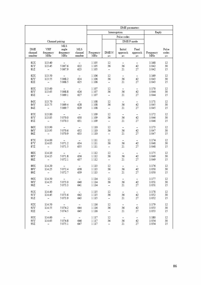
86

87
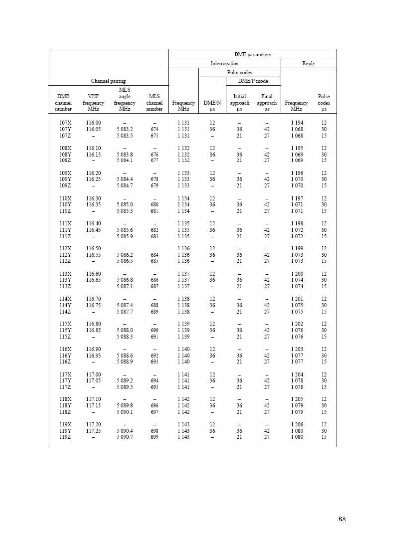
88

89

90
SCHEDULE 8
Regulation 44
SPECIFICATION FOR EN-ROUTE VHF MARKER BEACONS (75 MHZ)
1. Equipment
(1) Frequencies. The emissions of an en-route VHF marker beacon shall have a radio
frequency of 75 MHz plus or minus 0.005 per cent.
(2) Characteristics of emissions
(a) Radio marker beacons shall radiate an uninterrupted carrier modulated to a depth
of not less than 95 percent or more than 100 per cent. The total harmonic content
of the modulation shall not exceed 15 percent.
(b)The frequency of the modulating tone shall be 3 000 Hz plus or minus 75 Hz.
(c) The radiation shall be horizontally polarized.
(d)Identification. If a coded identification is required at a radio marker beacon, the
modulating tone shall be keyed so as to transmit dots or dashes or both in an
appropriate sequence. The mode of keying shall be such as to provide a dot-and-
dash duration together with spacing intervals corresponding to transmission at a
rate equivalent to approximately six to ten words per minute. The carrier shall not
be interrupted during identification.
(e) Determination of coverage. The limits of coverage of marker beacons shall be
determined on the basis of the field strength specified in Schedule 2 paragraph 3.
(2).
(f) Radiation pattern. The radiation pattern of a marker beacon normally shall be
such that the polar axis is vertical, and the field strength in the pattern is
symmetrical about the polar axis in the plane or planes containing the flight paths
for which the marker beacon is intended.
(3) Monitoring. For each marker beacon, suitable monitoring equipment shall be provided
which will show at an appropriate location:
(a) a decrease in radiated carrier power below 50 per cent of normal;
(b) a decrease of modulation depth below 70 per cent;
(c) a failure of keying.

91
SCHEDULE 9
Regulations 48, 49 and 50
REQUIREMENTS FOR THE GLOBAL NAVIGATION SATELLITE SYSTEM
(GNSS)
Table 9-1 Signal in space performance requirements
NOTES.—
1. The 95th percentile values for global navigation satellite system position errors are those
required for the intended operation at the lowest height above threshold (HAT), if applicable.
2. The definition of the integrity requirement includes an alert limit against which the
requirement can be assessed. For Category I precision approach, a vertical alert limit (VAL)
greater than 10 m for a specific system design may only be used if a system-specific safety
analysis has been completed. These alert limits are:

92
3. The accuracy and time-to-alert requirements include the nominal performance of a fault-
free receiver.
4. Ranges of values are given for the continuity requirement for en-route, terminal, initial
approach, NPA and departure operations, as this requirement is dependent upon several
factors including the intended operation, traffic density, complexity of airspace and
availability of alternative navigation aids. The lower value given is the minimum requirement
for areas with low traffic density and airspace complexity. The higher value given is
appropriate for areas with high traffic density and airspace complexity. Continuity
requirements for APV and Category I operations apply to the average risk (over time) of loss
of service, normalized to a 15-second exposure time.
5. A range of values is given for the availability requirements as these requirements are
dependent upon the operational need which is based upon several factors including the
frequency of operations, weather environments, the size and duration of the outages,
availability of alternate navigation aids, radar coverage, traffic density and reversionary
operational procedures. The lower values given are the minimum availabilities for which a
system is considered to be practical but are not adequate to replace non-global navigation
satellite system navigation aids. For en-route navigation, the higher values given are
adequate for global navigation satellite system to be the only navigation aid provided in an
area. For approach and departure, the higher values given are based upon the availability
requirements at airports with a large amount of traffic assuming that operations to or from
multiple runways are affected but reversionary operational procedures ensure the safety of
the operation.

93
6. A range of values is specified for Category I precision approach. The 4.0 m (13 feet)
requirement is based upon ILS specifications and represents a conservative derivation from
these specifications.
7. Global navigation satellite system performance requirements for Category II and III
precision approach operations are under review and will be included at a later date.
8. The terms APV-I and APV-II refer to two levels of global navigation satellite system
approach and landing operations with vertical guidance (APV) and these terms are not
necessarily intended to be used operationally.
1. Global navigation satellite system elements specifications
(1) Global positioning system Standard Positioning Service (SPS) (L1)
(a) Space and control segment accuracy
(i) Positioning accuracy. The GPS SPS position errors shall not exceed the
following limits:
Global average
95% of
the time
Worst site
95% of
the time
Horizontal position error
9 m (30ft)
17 m (56ft)
Vertical position error
15 m (49ft)
37 m (121ft)
(ii) Time transfer accuracy. The GPS SPS time transfer errors shall not
exceed 40 nanoseconds 95 per cent of the time.
(iii) Range domain accuracy. The range domain error shall not exceed the
following limits:
(aa) range error of any satellite — 30 m (100 ft) with reliability specified
paragraph (c);
(bb) 95th percentile range rate error of any satellite — 0.006 m (0.002 ft)
per second (global average);
(cc) 95th percentile range acceleration error of any satellite — 0.002 m
(0.006 ft) per second-squared (global average) and
(dd) 95th percentile range error for any satellites over all time differences
between time of data generation and time of use of data — 7.8 m
(26 ft) (global average).
(b) Availability. The Global Positioning System SPS availability shall be as follows:

94
(i) ≥99 per cent horizontal service availability, average location (17 m 95 per cent
threshold)
(ii) ≥99 per cent vertical service availability, average location (37 m 95 per cent
threshold)
(iii) ≥90 per cent horizontal service availability, worst-case location (17 m 95 per
cent threshold)
(iv) ≥90 per cent vertical service availability, worst-case location (37 m 95 per cent
threshold)
(c) Reliability. The GPS SPS reliability shall be within the following limits:
(i) reliability — at least 99.94 per cent (global average); and
(ii) reliability — at least 99.79 per cent (worst single point average).
(d) Probability of major service failure. The probability that the user range error (URE)
of any satellite will exceed 4.42 times the upper bound on the user range accuracy
(URA) broadcast by that satellite without an alert received at the user receiver antenna
within 10 seconds shall not exceed 1×10⁻⁵per hour.
(e) Continuity. The probability of losing Global Positioning System SPS signal-in-space
(SIS) availability from a slot of the nominal 24-slot constellation due to unscheduled
interruption shall not exceed 2×10⁻⁴ per hour.
(f) Coverage. The GPS SPS shall cover the surface of the earth up to an altitude of 3 000
kilometres.
(g) Radio frequency (RF) characteristics
(i) Carrier frequency. Each Global Positioning System satellite shall broadcast an
SPS signal at the carrier frequency of 1575.42 MHz (Global Positioning
System L1) using code division multiple access (CDMA).
(ii) Signal spectrum. The Global Positioning System SPS signal power shall be
contained within a ±12 MHz band (1563.42 – 1587.42 MHz) centred on the L1
frequency.
(iii) Polarization. The transmitted RF signal shall be right-hand (clockwise)
circularly polarized.
(iv) Signal power level. Each Global Positioning System satellite shall
broadcast SPS navigation signals with sufficient power such that, at all
unobstructed locations near the ground from which the satellite is observed at
an elevation angle of 5 degrees or higher, the level of the received RF signal at
the antenna port of a 3 dBi linearly-polarized antenna is within the range of –
158.5 dBW to –153 dBW for all antenna orientations orthogonal to the
direction of propagation.
(v) Modulation. The SPS L1 signal shall be bipolar phase shift key (BPSK)
modulated with a pseudo random noise (PRN) 1.023 MHz coarse/acquisition
(C/A) code. The C/A code sequence shall be repeated each millisecond. The

95
transmitted PRN code sequence shall be the Modulo-2 addition of 50 bits per
second navigation message and the C/A code.
(h) Global Positioning System time. Global Positioning System time shall be referenced
to UTC (as maintained by the U.S. Naval Observatory).
(i) Coordinate system. The Global Positioning System coordinate system shall be WGS-
84.
(j) Navigation information. The navigation data transmitted by the satellites shall
include the necessary information to determine:
(i) satellite time of transmission;
(ii) satellite position;
(iii) satellite health;
(iv) satellite clock correction;
(v) propagation delay effects;
(vi) time transfer to UTC; and
(vii) Constellation status.
(2) GLONASS Channel of Standard Accuracy (CSA) (L1)
(a) Space and control segment accuracy
(i) Positioning accuracy. The GLONASS CSA position errors shall not exceed the
following limits:
Global average
95% of the time
Worst site
95% of the time
Horizontal position error
5 m (17 ft)
12 m (40 ft)
Vertical position error
9 m (29 ft)
25 m (97 ft)
(ii) Time transfer accuracy. The GLONASS CSA time transfer errors shall not
exceed 700 nanoseconds 95 per cent of the time.
(iii) Range domain accuracy. The range domain error shall not exceed the
following limits:
(i) range error of any satellite — 18 m (59.7 ft);
(ii) range rate error of any satellite — 0.02 m (0.07 ft) per second;
(iii)range acceleration error of any satellite — 0.007 m (0.023 ft) per second
squared;
(iv) root-mean-square range error over all satellites — 6 m (19.9 ft).
(b) Availability. The GLONASS CSA availability shall be as follows-
(i) ≥99 per cent horizontal service availability, average location (12 m, 95 per
cent threshold);
(ii) ≥99 per cent vertical service availability, average location (25 m, 95 per
cent threshold);

96
(iii)≥90 per cent horizontal service availability, worst-case location (12 m, 95
per cent threshold);
(iv) ≥90 per cent vertical service availability, worst-case location (25 m, 95 per
cent threshold).
(c) Reliability. The GLONASS CSA reliability shall be within the following limits-
(i) frequency of a major service failure — not more than three per year for the
constellation (global average); and
(ii) reliability- at least 99.7 per cent (global average).
(d) Coverage. The GLONASS CSA shall cover the surface of the earth up to an altitude
of 2 000 km.
(e) RF characteristics
(i) Carrier frequency. Each GLONASS satellite shall broadcast CSA navigation
signal at its own carrier frequency in the L1 (1.6 GHz) frequency band using
frequency division multiple access (FDMA).
(ii) Signal spectrum. GLONASS CSA signal power shall be contained within a
±5.75 MHz band centred on each GLONASS carrier frequency.
(iii) Polarization. The transmitted RF signal shall be right-hand circularly
polarized.
(iv) Signal power level. Each GLONASS satellite shall broadcast CSA navigation
signals with sufficient power such that, at all unobstructed locations near the
ground from which the satellite is observed at an elevation angle of 5 degrees
or higher, the level of the received RF signal at the antenna port of a 3 dBi
linearly polarized antenna is within the range of –161 dBW to –155.2 dBW for
all antenna orientations orthogonal to the direction of propagation.
(v) Modulation
(aa) Each GLONASS satellite shall transmit at its carrier frequency the
navigation RF signal using a BPSK modulated binary train. The
phase shift keying of the carrier shall be performed at π-radians
with the maximum error ±0.2 radian. The pseudo-random code
sequence shall be repeated each millisecond.
(bb) The modulating navigation signal shall be generated by the
Modulo-2 addition of the following three binary signals-
(i) ranging code transmitted at 511 kbits/s;
(ii) navigation message transmitted at 50 bits/s; and
(iii)100 Hz auxiliary meander sequence.
(f) GLONASS time. GLONASS time shall be referenced to UTC (SU) (as maintained by
the National Time Service of Russia).
(g) Coordinate system. The GLONASS coordinate system shall be PZ-90.

97
(h) Navigation information. The navigation data transmitted by the satellite shall include
the necessary information to determine:
(i) satellite time of transmission;
(ii) satellite position;
(iii) satellite health;
(iv) satellite clock correction;
(v) time transfer to UTC; and
(vi) constellation status.
(3) Aircraft-based augmentation system (ABAS)
The ABAS function combined with one or more of the other global navigation satellite
system elements and both a fault free global navigation satellite system receiver and fault-
free aircraft system used for the ABAS function shall meet the requirements for accuracy,
integrity, continuity and availability as stated in Regulation 48. in 9.0.
(4) Satellite-based augmentation system (SBAS)
(a) Performance. SBAS combined with one or more of the other global navigation
satellite system elements and a fault-free receiver shall meet the requirements for
system accuracy, integrity, continuity and availability for the intended operation as
stated in Regulation 48. 9.0.
(b) Functions. SBAS shall perform one or more of the following functions-
(i) ranging: provide an additional pseudo-range signal with an accuracy
indicator from an SBAS satellite;
(ii) global navigation satellite system satellite status: determine and transmit
the global navigation satellite system satellite health status;
(iii)basic differential correction: provide global navigation satellite system
satellite ephemeris and clock corrections (fast and long-term) to be
applied to the pseudo-range measurements from satellites; and
(iv) precise differential correction: determine and transmit the ionospheric
corrections.
(c) Ranging
(i) Excluding atmospheric effects, the range error for the ranging signal
from SBAS satellites shall not exceed 25 m (82 ft) (95 per cent).
(ii) The probability that the range error exceeds 150 m (490 ft) in any hour
shall not exceed 10–5.
(iii)The probability of unscheduled outages of the ranging function from an
SBAS satellite in any hour shall not exceed 10–3.
(iv) The range rate error shall not exceed 2 m (6.6 ft) per second.
(v) The range acceleration error shall not exceed 0.019 m (0.06 ft) per
second-squared.
(d) Service area. The SBAS service area shall be a defined area within an SBAS
coverage area where SBAS meets the requirements of 9.0 and supports the
corresponding approved operations.

98
(e) RF characteristics
(i) Carrier frequency. The carrier frequency shall be 1 575.42 MHz.
(ii) Signal spectrum. At least 95 per cent of the broadcast power shall be contained
within a ±12 MHz band centred on the L1 frequency. The bandwidth of the
signal transmitted by an SBAS satellite shall be at least 2.2 MHz.
(f) SBAS satellite signal power level.
(i) Each SBAS satellite placed in orbit before 1 January 2014 shall broadcast
navigation signals with sufficient power such that, at all unobstructed locations
near the ground from which the satellite is observed at an elevation angle of 5
degrees or higher, the level of the received RF signal at the antenna port of a 3
dBi linearly polarized antenna is within the range of –161 dBW to –153 dBW
for all antenna orientations orthogonal to the direction of propagation.
(ii) Each SBAS satellite placed in orbit after 31 December 2013 shall comply with
the following requirements-
(aa) The satellite shall broadcast navigation signals with sufficient
power such that, at all unobstructed locations near the ground from
which the satellite is observed at or above the minimum elevation
angle for which a trackable GEO signal needs to be provided, the
level of the received RF signal at the antenna port of the antenna
specified in Table 9-2, is at least –164.0 dBW.
(bb) Minimum elevation angle. The minimum elevation angle used
to determine GEO coverage shall not be less than 5 degrees for a
user near the ground.
(cc) The level of a received SBAS RF signal at the antenna port of a
0 dBic antenna located near the ground shall not exceed –152.5
dBW.
(dd) The ellipticity of the broadcast signal shall be no worse than 2
dB for the angular range of ±9.1° from boresight.
Table 9-2 Minimum antenna gain- GPS, GLONASS and SBAS
Evaluation angle degrees Minimum gain dBic
0 -7
5 -5-5
10 -4
15 to 90 -2.5
(g) Polarization. The broadcast signal shall be right-hand circularly polarized.
(h) Modulation. The transmitted sequence shall be the Modulo-2 addition of the
navigation message at a rate of 500 symbols per second and the 1 023 bit pseudo-

99
random noise code. It shall then be BPSK-modulated onto the carrier at a rate of
1.023 megachips per second.
(i) SBAS network time (SNT). The difference between SNT and Global Positioning
System time shall not exceed 50 nanoseconds.
(j) Navigation information. The navigation data transmitted by the satellites shall include
the necessary information to determine-
(i) SBAS satellite time of transmission;
(ii) SBAS satellite position;
(iii) corrected satellite time for all satellites;
(iv) corrected satellite position for all satellites;
(v) ionospheric propagation delay effects;
(vi) user position integrity;
(vii) time transfer to UTC; and
(viii) service level status.
(5) Ground-based augmentation system (GBAS) and ground-based regional augmentation
system (GRAS)
(a) Performance. GBAS combined with one or more of the other global navigation satellite
system elements and a fault-free global navigation satellite system receiver shall meet the
requirements for system accuracy, continuity, availability and integrity for the intended
operation as stated Regulation 48. in 9.0.
(b) Functions. GBAS shall perform the following functions-
(i) provide locally relevant pseudo-range corrections;
(ii) provide GBAS-related data;
(iii)provide final approach segment data when supporting precision approach;
(iv) provide predicted ranging source availability data; and
(v) provide integrity monitoring for global navigation satellite system ranging sources.
(c) Coverage
(i) For Category I precision approach and approach with vertical guidance, the GBAS
coverage to support each Category I precision approach or approach with vertical
guidance shall be as follows, except where topographical features dictate and
operational requirements permit-
(aa) laterally, beginning at 140 m (450 ft) each side of the landing threshold
point/fictitious threshold point (LTP/FTP) and projecting out ±35 degrees either
side of the final approach path to 28 km (15 NM) and ±10 degrees either side of
the final approach path to 37 km (20 NM); and
(bb) vertically, within the lateral region, up to the greater of 7 degrees or 1.75
promulgated glide path angle (GPA) above the horizontal with an origin at the
glide path interception point (GPIP) and 0.45 GPA above the horizontal or to
such lower angle, down to 0.30 GPA, as required, to safeguard the promulgated
glide path intercept procedure. This coverage applies between 30 m (100 ft) and 3
000 m (10 000 ft) height above threshold (HAT).

100
(ii) For Category I precision approach, the data broadcast as specified in subparagraph (6)
shall extend down to 3.7 m (12 ft) above the runway surface.
(vi) The data broadcast shall be omni-directional when required to support
the intended applications.
(vii) GBAS positioning service. The GBAS positioning service area shall be
that area where the data broadcast can be received and the positioning
service meets the requirements of 9.0 and supports the corresponding
approved operations.
(6) Data broadcast characteristics
(a) Carrier frequency. The data broadcast radio frequencies used shall be selected from
the radio frequencies in the band 108 to 117.975 MHz. The lowest assignable
frequency shall be 108.025 MHz and the highest assignable frequency shall be
117.950 MHz. The separation between assignable frequencies (channel spacing) shall
be 25 kHz.
(b) Access technique. A time division multiple access (TDMA) technique shall be used
with a fixed frame structure. The data broadcast shall be assigned one to eight slots.
(c) Modulation. GBAS data shall be transmitted as 3-bit symbols, modulating the data
broadcast carrier by D8PSK, at a rate of 10 500 symbols per second.
(d) Data broadcast RF field strength and polarization
(i) GBAS/H
(aa) A horizontally polarized signal shall be broadcast.
(bb) The effective radiated power (ERP) shall provide for a
horizontally polarized signal with a minimum field strength of 215
microvolts per metre (–99 dBW/m2) and a maximum field
strength of 0.350 volts per metre (–35 dBW/m2) within the GBAS
coverage volume. The field strength shall be measured as an
average over the period of the synchronization and ambiguity
resolution field of the burst. The RF phase offset between the
HPOL and any VPOL components shall be such that the minimum
signal power is achieved for HPOL users throughout the coverage
volume.
(ii) GBAS/E
(aa) An elliptically polarized signal shall be broadcast whenever practical;
(bb) When an elliptically polarized signal is broadcast, the horizontally
polarized component shall meet the requirements in subparagraph (i)
(bb) and the effective radiated power (ERP) shall provide for a
vertically polarized signal with a minimum field strength of 136
microvolts per metre (–103 dBW/m2) and a maximum field strength of
0.221 volts per metre (–39 dBW/m2) within the GBAS coverage

101
volume. The field strength shall be measured as an average over the
period of the synchronization and ambiguity resolution field of the
burst. The RF phase offset between the HPOL and VPOL components,
shall be such that the minimum signal power is achieved for HPOL and
VPOL users throughout the coverage volume.
(iii) Power transmitted in adjacent channels. The amount of power during
transmission under all operating conditions when measured over a 25 kHz
bandwidth centred on the ith adjacent channel shall not exceed the values shown in
Table 9.3.
Table 9.3 GBAS broadcast power transmitted in adjacent channels
(iv) Unwanted emissions. Unwanted emissions, including spurious and out-of-
band emissions, shall be compliant with the levels shown in Table 9.4. The total
power in any VDB harmonic or discrete signal shall not be greater than –53 dBm.
Table 9.4 GBAS broadcast unwanted emissions
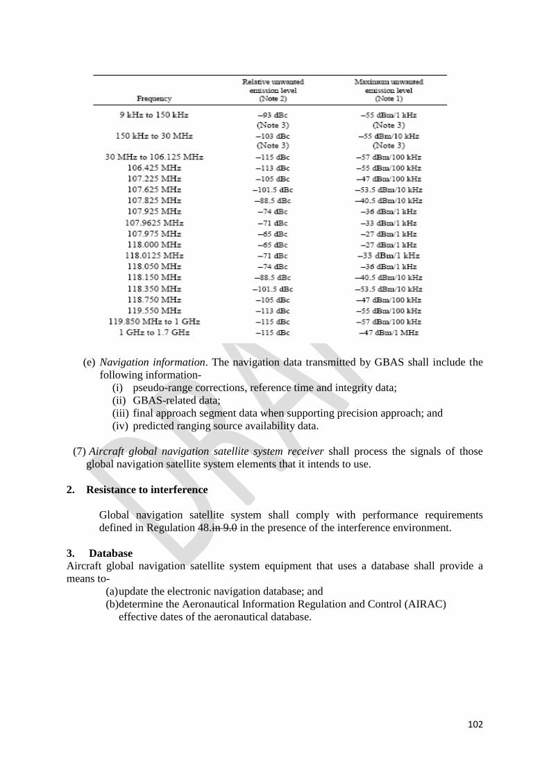
102
(e) Navigation information. The navigation data transmitted by GBAS shall include the
following information-
(i) pseudo-range corrections, reference time and integrity data;
(ii) GBAS-related data;
(iii) final approach segment data when supporting precision approach; and
(iv) predicted ranging source availability data.
(7) Aircraft global navigation satellite system receiver shall process the signals of those
global navigation satellite system elements that it intends to use.
2. Resistance to interference
Global navigation satellite system shall comply with performance requirements
defined in Regulation 48.in 9.0 in the presence of the interference environment.
3. Database Aircraft global navigation satellite system equipment that uses a database shall provide a
means to-
(a) update the electronic navigation database; and
(b)determine the Aeronautical Information Regulation and Control (AIRAC)
effective dates of the aeronautical database.

103
SCHEDULE 10
Regulation 51
SYSTEM CHARACTERISTICS OF AIRBORNE ADF RECEIVING SYSTEMS
Accuracy of bearing indication
The bearing given by the ADF system shall not be in error by more than plus or minus 5
degrees with a radio signal from any direction having a field strength of 70 microvolts per
metre or more radiated from an LF/MF NDB or locator operating within the tolerances
permitted by this Manual and in the presence also of an unwanted signal from a direction 90
degrees from the wanted signal and-
(a) on the same frequency and 15 dB weaker; or
(b) plus or minus 2 kHz away and 4 dB weaker; or
(c) plus or minus 6 kHz or more away and 55 dB stronger.
Cross Reference
Civil Aviation (Certification of Air Navigation Services) Regulations, 2019
Air Navigation (Aeronautical Information Services) Regulations 2019
Civil Aviation (Construction of Visual and Instrument Flight Procedures) Regulations 2019.
………………………………….
HON. MONICAL AZUBA NTEGE
Minister of Works and Transport