The Centrifugal Pump
31
The Centrifugal Pump 1
description
The Centrifugal Pump. Structure of the Centrifugal Pump. Centrifugal pump has two main components: an impeller and a stationary casing, housing, or volute. - PowerPoint PPT Presentation
Transcript of The Centrifugal Pump

1
The Centrifugal Pump
2
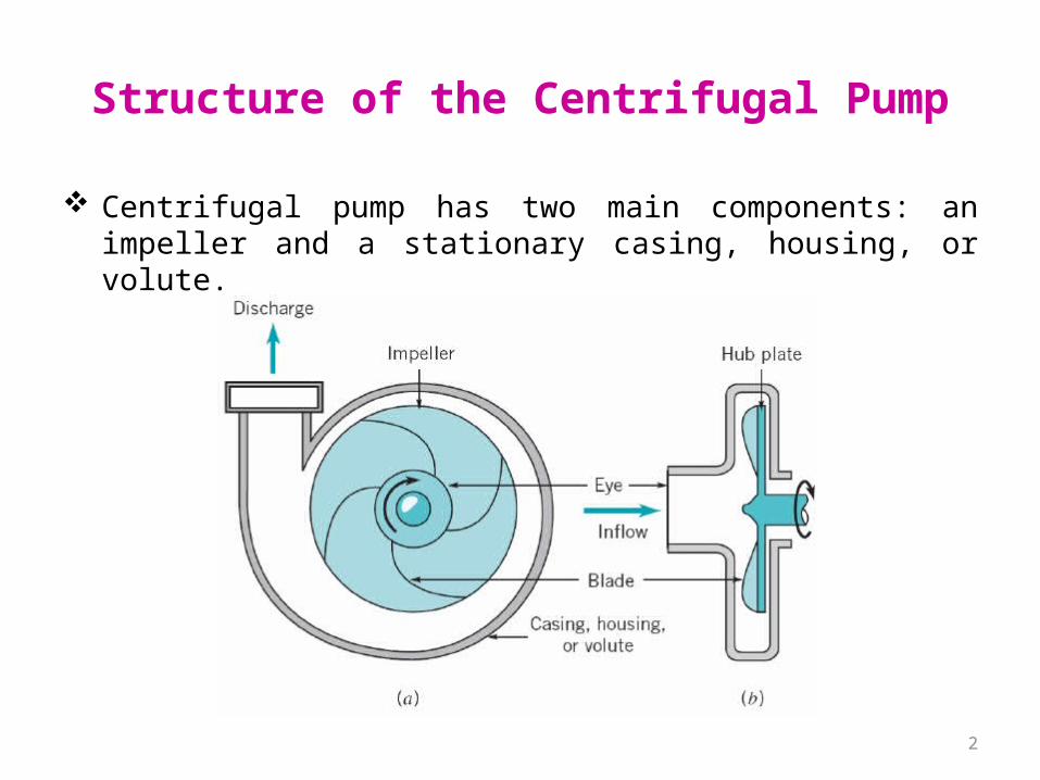
Structure of the Centrifugal Pump
Centrifugal pump has two main components: an impeller and a stationary casing, housing, or volute.
3
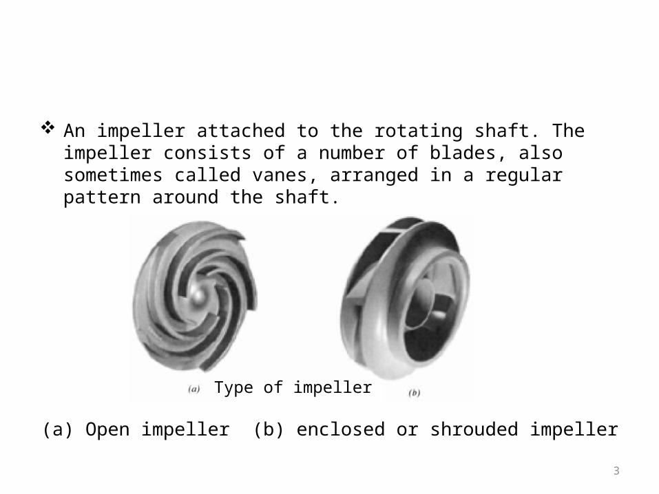
An impeller attached to the rotating shaft. The impeller consists of a number of blades, also sometimes called vanes, arranged in a regular pattern around the shaft.
(a) Open impeller (b) enclosed or shrouded impellerType of impeller
4
A stationary casing, housing, or volute enclosing the impeller.– The casing shape is designed to reduce the velocity as
the fluid leaves the impeller, and this decrease in kinetic energy is converted into an increase in pressure.
– The volute-shaped casing, with its increase area in the direction of flow, is used to produce an essentially uniform velocity distribution as the fluid moves around the casing into the discharge opening.
5
Operation of the Centrifugal Pump
As the impeller rotates, fluid is sucked in through the eye of the casing and flows radially outward.
Energy is added to the fluid by the rotating blades, and both pressure and absolute velocity are increased as the fluid lows from the eye to the periphery of the blades.
6
Stages of the Centrifugal Pump
Simple stage pump: Only one impeller is mounted on the shaft.
Multistage pump: Several impellers are mounted on the same shaft.– The flowrate is the same through all stages.– Each stage develops an additional pressure rise.– For a very large discharge pressure.
7
Theoretical Considerations
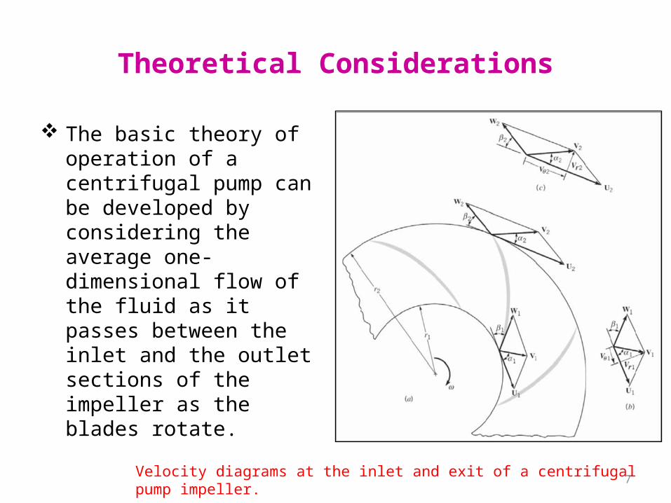
The basic theory of operation of a centrifugal pump can be developed by considering the average one-dimensional flow of the fluid as it passes between the inlet and the outlet sections of the impeller as the blades rotate.
Velocity diagrams at the inlet and exit of a centrifugal pump impeller.
8
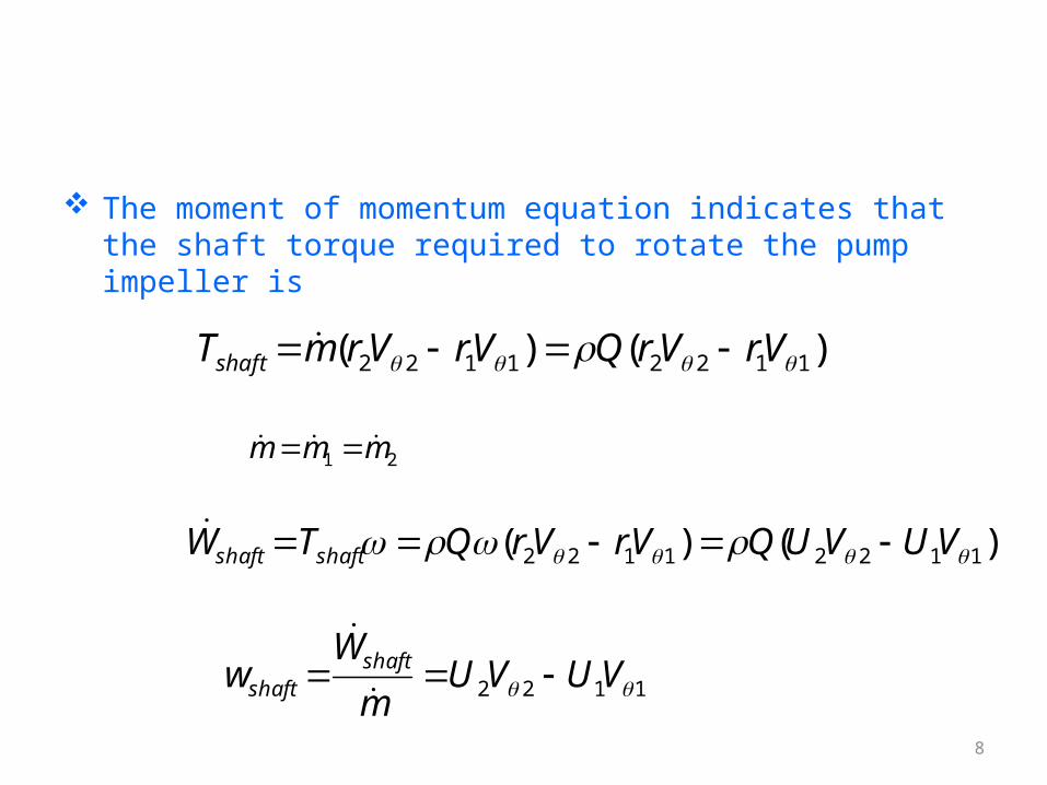
The moment of momentum equation indicates that the shaft torque required to rotate the pump impeller is
)()( 11221122 VrVrQVrVrmTshaft
21 mmm
)()( 11221122 VUVUQVrVrQTW shaftshaft
1122 VUVUm
Ww shaft
shaft
9
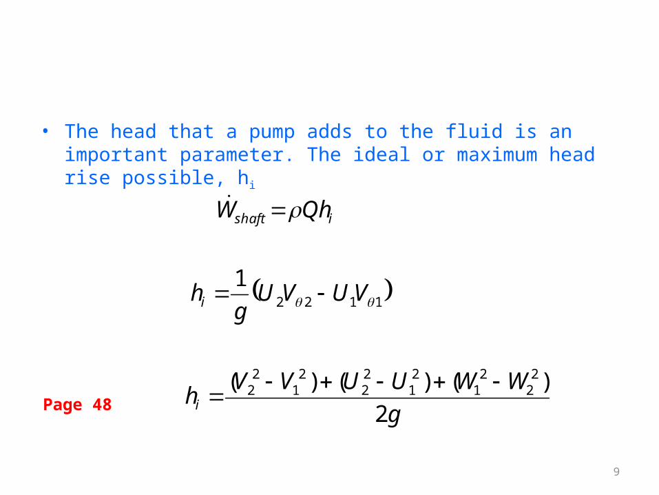
• The head that a pump adds to the fluid is an important parameter. The ideal or maximum head rise possible, hi
gWWUUVVhi 2
)()()( 22
21
21
22
21
22
ishaft QhW
11221
VUVUg
hi
Page 48
10
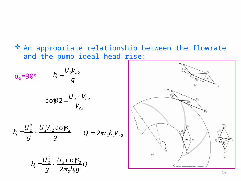
An appropriate relationship between the flowrate and the pump ideal head rise:
α0=900gVUhi
22
2
222cotrVVU
gVU
gUh r
i222
22 cot
2222 rVbrQ
Qgbr
Ug
Uhi22
2222
2cot
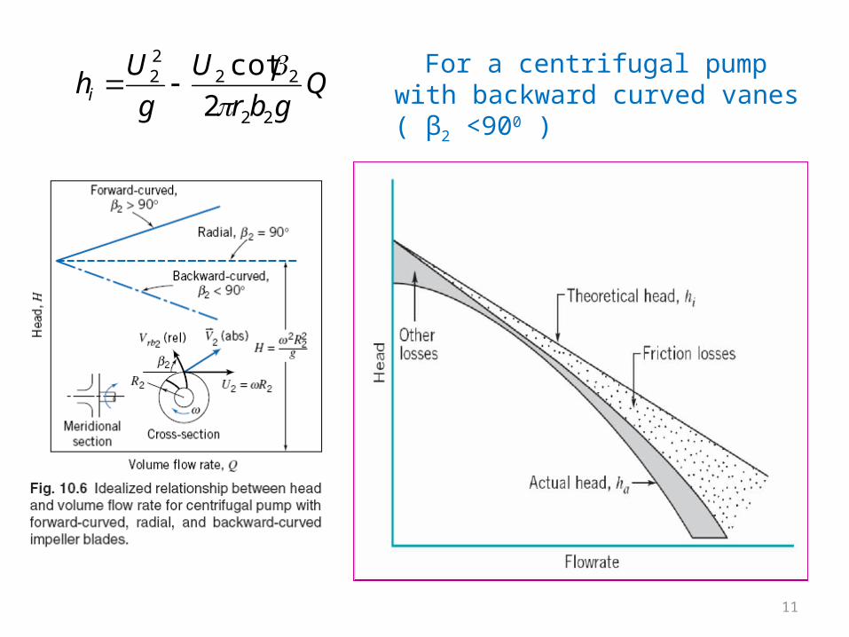
11
For a centrifugal pump with backward curved vanes ( β2 <900 )
Qgbr
Ug
Uhi22
2222
2cot
12
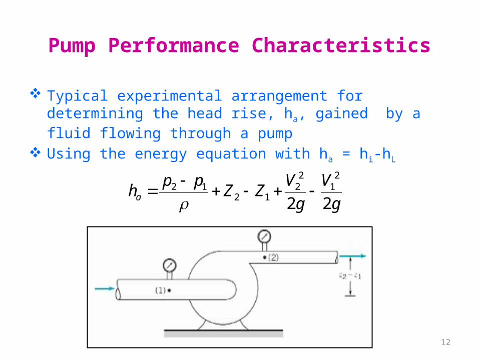
Pump Performance Characteristics
Typical experimental arrangement for determining the head rise, ha, gained by a fluid flowing through a pump
Using the energy equation with ha = hi-hL
gV
gVZZppha 22
21
22
1212
13
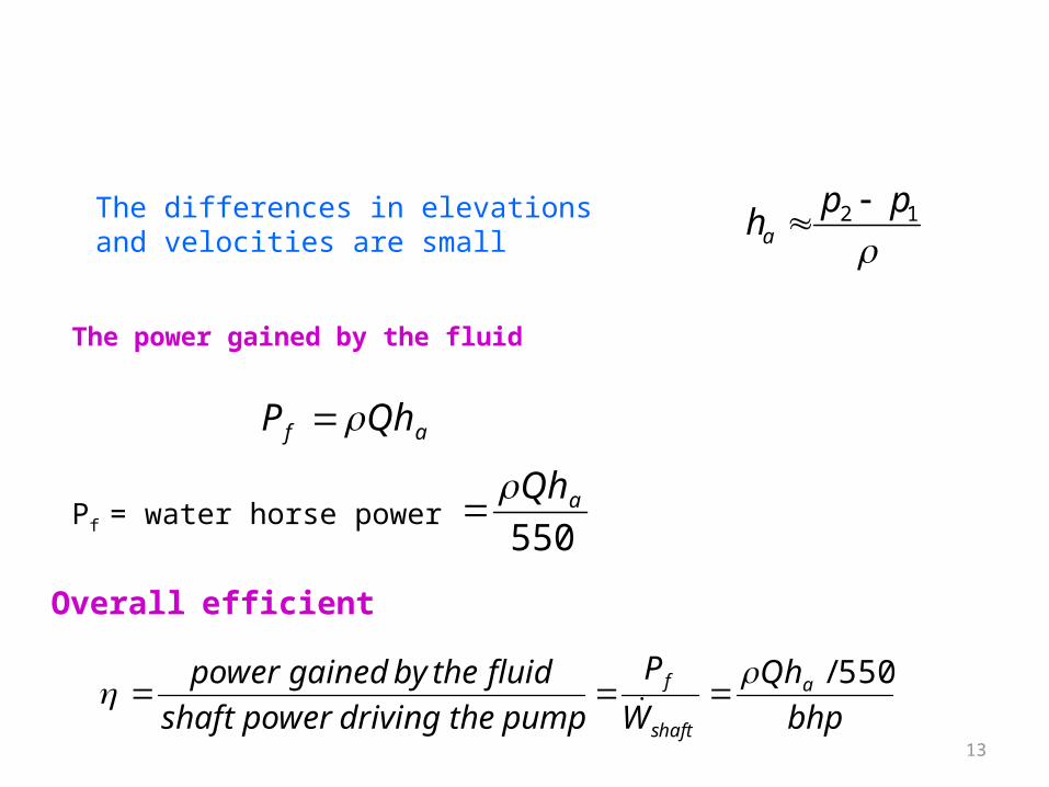
The differences in elevations and velocities are small
12 ppha
The power gained by the fluid
af QhP
Pf = water horse power550
aQh
Overall efficient
bhpQh
WP
pumpthedrivingpowershaftfluidthebygainedpower a
shaft
f 550/
14
The overall pump efficiency is affected by the hydraulic losses in the pump, and in addition, by the mechanical losses in the bearings and seals.
There may also be some power loss due to leakage of the fluid between the back surface of the impeller hub plate and the casing, or through other pump components.
This leakage contribution to the overall efficiency is called the volumetric loss.
15
The overall efficiency arises from three source, the hydraulic efficiency, ηh, the mechanical efficiency, ηm ,and the volumetric efficiency, ηv
η = ηh ηm ηv
16
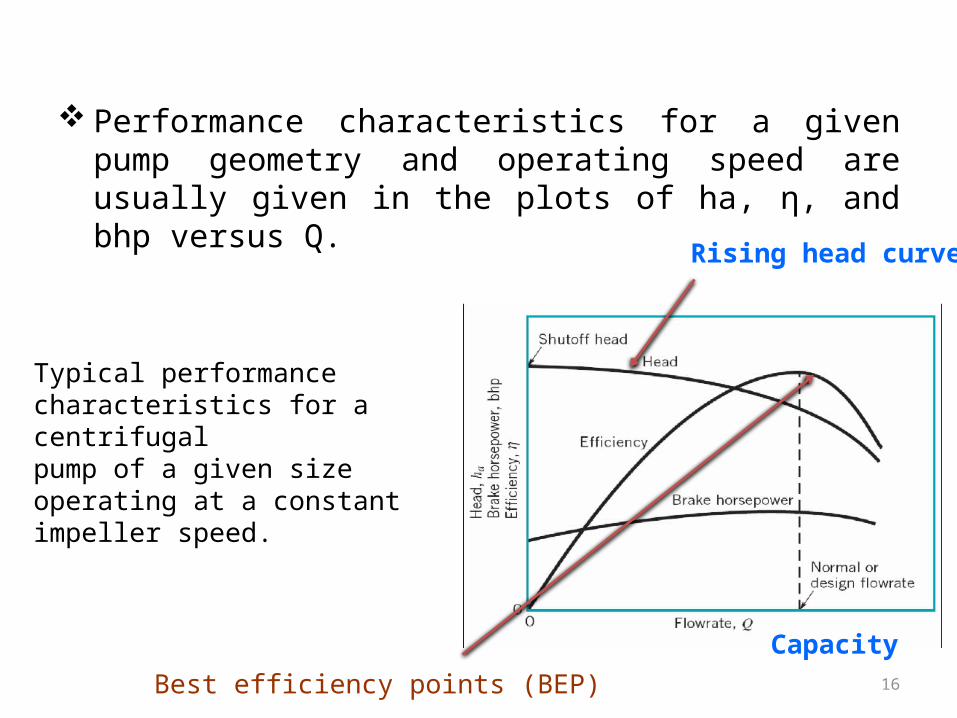
Performance characteristics for a given pump geometry and operating speed are usually given in the plots of ha, η, and bhp versus Q.
Typical performancecharacteristics for a centrifugalpump of a given size operating at a constant impeller speed.
Best efficiency points (BEP)
Rising head curve
Capacity
17
Rise head curve: the head curve continuously rises as the flowrate decreases.
Falling head curve: ha-Q curves initially rise as Q is decreased from the design value and then fall with a continued decrease in Q.
Shutoff head: the head developed by the pump at zero discharge. It represents the rise in pressure head across the pump with the discharge valve closed.
Best efficiency points (BEP): the points on the variouscurves corresponding to the maximum efficiency.
18
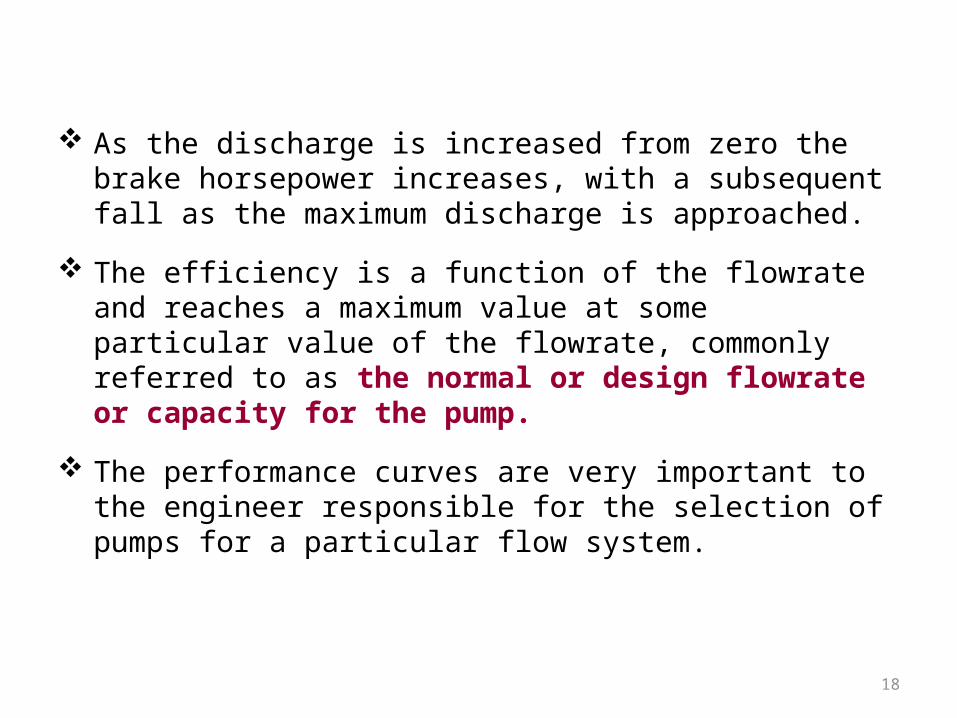
As the discharge is increased from zero the brake horsepower increases, with a subsequent fall as the maximum discharge is approached.
The efficiency is a function of the flowrate and reaches a maximum value at some particular value of the flowrate, commonly referred to as the normal or design flowrate or capacity for the pump.
The performance curves are very important to the engineer responsible for the selection of pumps for a particular flow system.
19
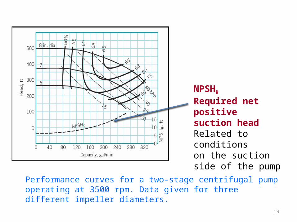
NPSHRRequired net positivesuction headRelated to conditionson the suction side of the pump
Performance curves for a two-stage centrifugal pump operating at 3500 rpm. Data given for three different impeller diameters.
20
Net Positive Suction Head
On the suction side of a pump, low pressures are commonly encountered, with the concomitant possibility of cavitation occurring within the pump.
Cavitation occurs when the liquid pressure at a given location is reduced to the vapor pressure of the liquid. When this occurs, vapor bubbles form; this phenomenon can cause a loss in efficiency as well as structural damage to the pump.
How to characterize the potential for cavitation…
21
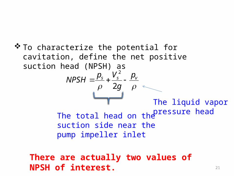
To characterize the potential for cavitation, define the net positive suction head (NPSH) as
vss p
gVpNPSH 2
2
The liquid vaporpressure headThe total head on the
suction side near the pump impeller inlet
There are actually two values of NPSH of interest.
22
NPSHR and NPSHA
Required NPSH, denoted NPSHR, that must be maintained, or exceeded, so that cavitation will not occur. Since pressure lower than those in the suction pipe will develop in the impeller eye, it is usually necessary to determine experimentally, for a given pump, the required NPSHR.
• Available NPSH, denoted NPSHA, represents the head that actually occurs for the particular flow system. This value can be determined experimentally, or calculated if the system parameters are known.
23
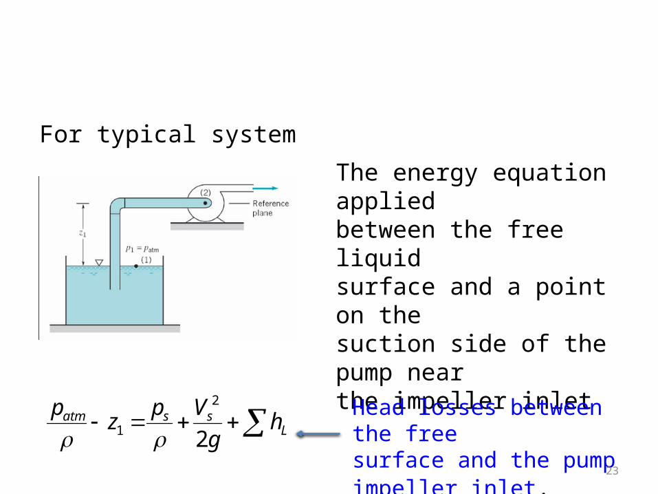
For typical system
The energy equation appliedbetween the free liquidsurface and a point on thesuction side of the pump nearthe impeller inlet
Lssatm hg
Vpzp2
2
1 Head losses between the freesurface and the pumpimpeller inlet.
24
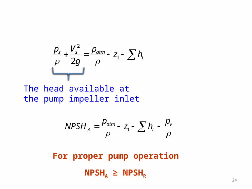
Latmss hzp
gVp
1
2
2
The head available atthe pump impeller inlet
v
Latm
AphzpNPSH 1
NPSHA ≥ NPSHR
For proper pump operation
25
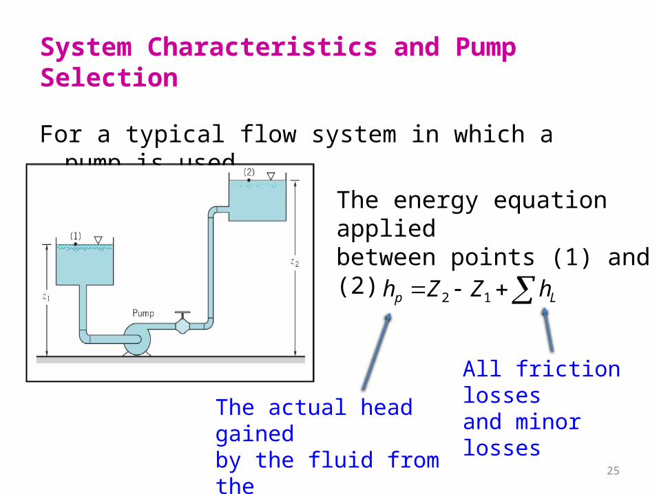
System Characteristics and Pump Selection
For a typical flow system in which a pump is used
The energy equation appliedbetween points (1) and (2)
Lp hZZh 12
The actual head gainedby the fluid from thepump.
All friction lossesand minor losses
26
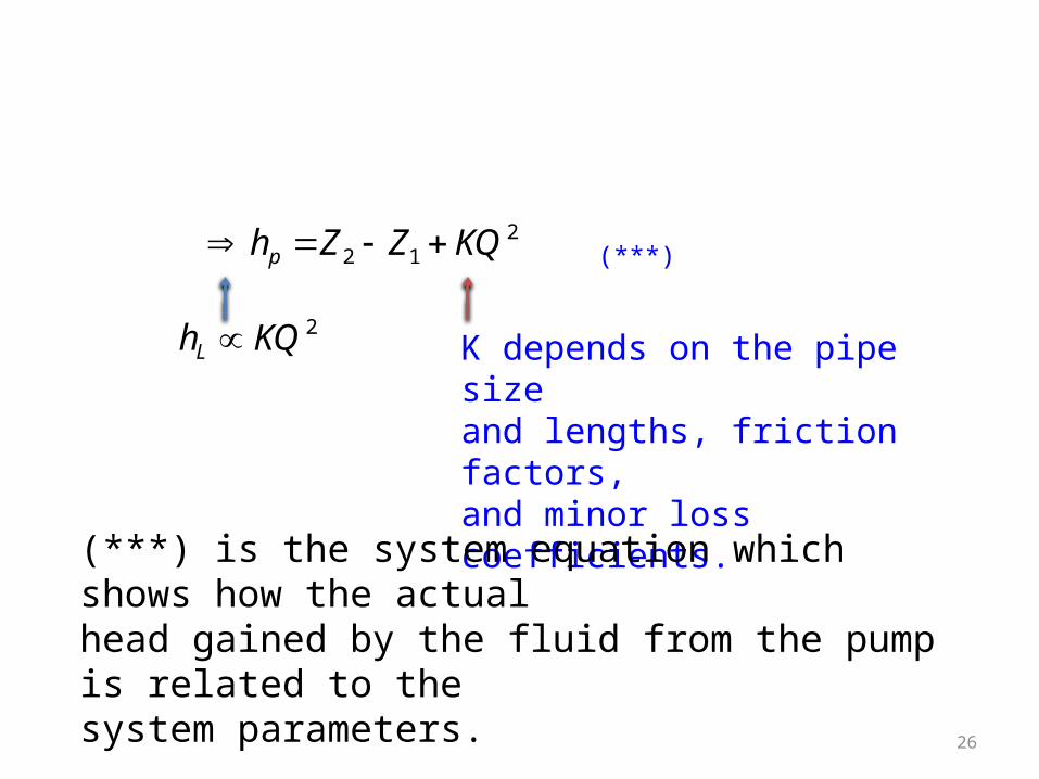
212 KQZZhp
2KQhL K depends on the pipe sizeand lengths, friction factors,and minor loss coefficients.
(***)
(***) is the system equation which shows how the actualhead gained by the fluid from the pump is related to thesystem parameters.
27
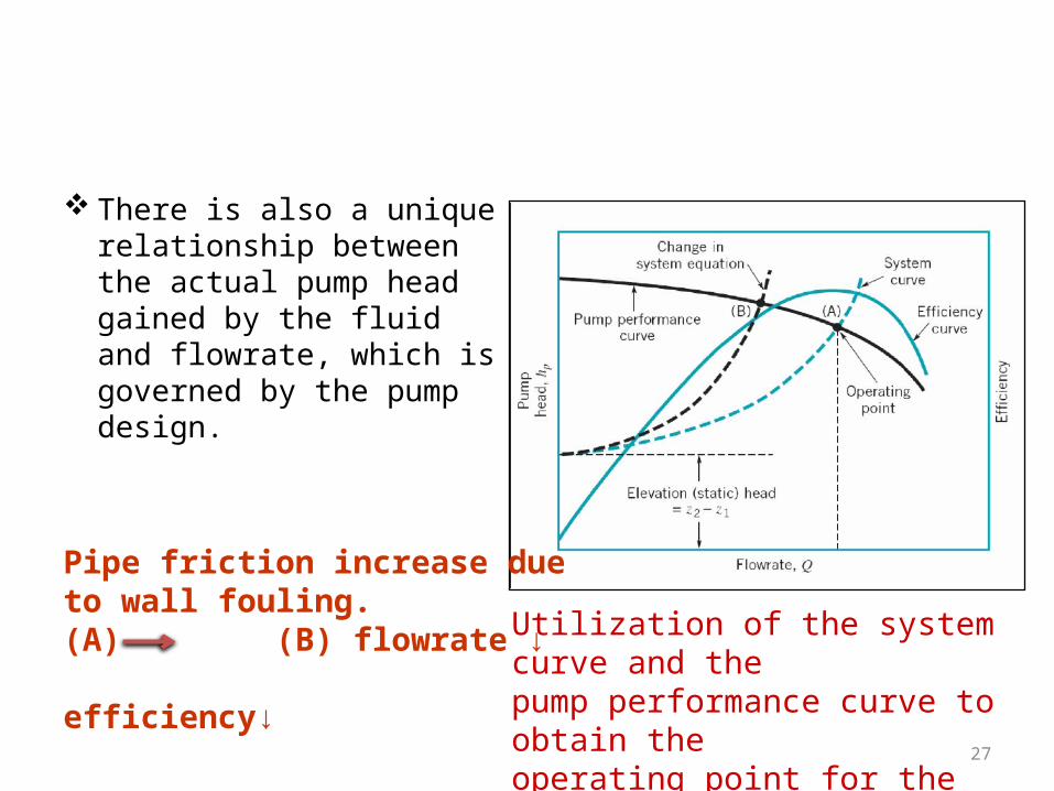
There is also a unique relationship between the actual pump head gained by the fluid and flowrate, which is governed by the pump design.
Utilization of the system curve and thepump performance curve to obtain theoperating point for the system.
Pipe friction increase dueto wall fouling.(A) (B) flowrate ↓ efficiency↓
28
To select a pump for a particular application, it is necessary to utilize both the system curve, determined by the system equation, and the pump performance curve.
The intersection of both curves represents the operating point for the system.
– The operating point wanted to be near the best efficiency point (BEP).
29
Pumps in Series or Parallel
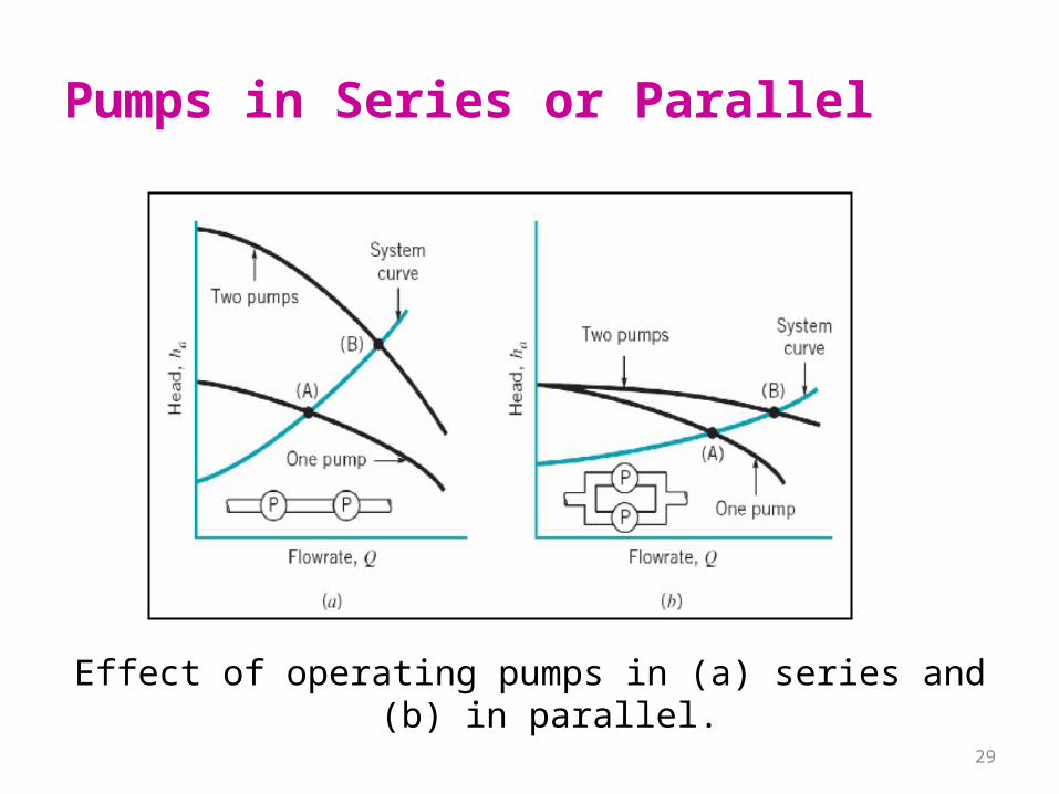
Effect of operating pumps in (a) series and (b) in parallel.
30
When two pumps are placed in series
– The resulting pump performance curve is obtained by adding heads at the same flowrate.
– Both the actual head and the flowrate are increased but neither will be doubled.
– The operating point is moved from (A) to (B).
31
When two pumps are placed in parallel– The combined performance curve is obtained by
adding flowrate at the same head.
– The flowrate is increased significantly, but not be doubled.
– The operating point is moved from (A) to (B).