The Cellular Concept - KFUPMfaculty.kfupm.edu.sa/EE/zummo/EE577/Ch03_CellularConcepts.pdf · The...
47
1 EE577 - Salam A. Zummo 1 Chapter 3 The Cellular Concept Dr. Salam A. Zummo Associate Professor, EE EE577 - Salam A. Zummo 2 Topics Basics of cellular structure Handoff Interference Trunking Coverage and Capacity
-
Upload
nguyenthuy -
Category
Documents
-
view
216 -
download
1
Transcript of The Cellular Concept - KFUPMfaculty.kfupm.edu.sa/EE/zummo/EE577/Ch03_CellularConcepts.pdf · The...

1
EE577 - Salam A. Zummo 1
Chapter 3
The Cellular Concept
Dr. Salam A. ZummoAssociate Professor, EE
EE577 - Salam A. Zummo 2
Topics
Basics of cellular structureHandoffInterferenceTrunkingCoverage and Capacity
2
EE577 - Salam A. Zummo 3
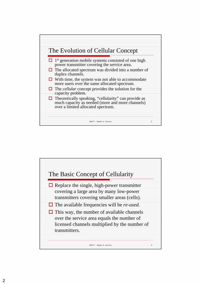
The Evolution of Cellular Concept 1st generation mobile systems consisted of one high power transmitter covering the service area.The allocated spectrum was divided into a number of duplex channels. With time, the system was not able to accommodate more users over the same allocated spectrum.The cellular concept provides the solution for the capacity problem.Theoretically speaking, “cellularity” can provide as much capacity as needed (more and more channels) over a limited allocated spectrum.
EE577 - Salam A. Zummo 4
The Basic Concept of Cellularity
Replace the single, high-power transmitter covering a large area by many low-power transmitters covering smaller areas (cells).The available frequencies will be re-used.This way, the number of available channels over the service area equals the number of licensed channels multiplied by the number of transmitters.
3
EE577 - Salam A. Zummo 5
The Cellular AdvantageCluster patterns and the corresponding frequencies are re-used in a regular pattern over the entire service area
System Capacity (number of users that system can serve simultaneously) can be increased if C is made smaller
Capacity can be increased by reducing the size of the cells and increasing their number
EE577 - Salam A. Zummo 6
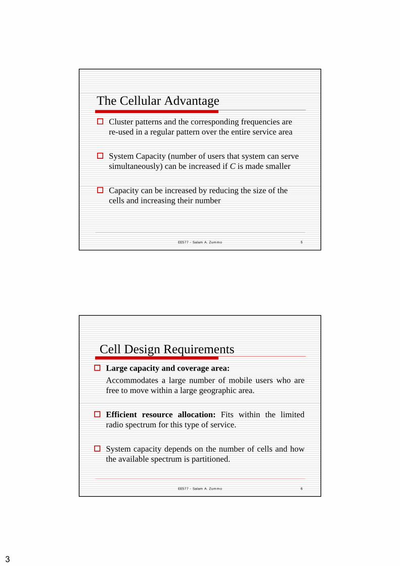
Cell Design RequirementsLarge capacity and coverage area:Accommodates a large number of mobile users who are free to move within a large geographic area.
Efficient resource allocation: Fits within the limited radio spectrum for this type of service.
System capacity depends on the number of cells and how the available spectrum is partitioned.

4
EE577 - Salam A. Zummo 7
Cellular Systems Essential Elements
Low power transmitters: cover small areas (cells)
Spectrum (frequency) reuse
Handoff: Switching ongoing calls between cells (channels)
EE577 - Salam A. Zummo 8
Cell Design ProblemHow to allocate frequencies so that:
Calls do not interfere with each otherUsers have low probability of blockingA large user pool can be accommodated given the limited spectrum

5
EE577 - Salam A. Zummo 9
Components of Cellular Systems
A cellular system consists mainly of:
Mobile station (MS)Base station (BS)Mobile Switching Center (MSC)
EE577 - Salam A. Zummo 10
6
EE577 - Salam A. Zummo 11
Base Station (BS)
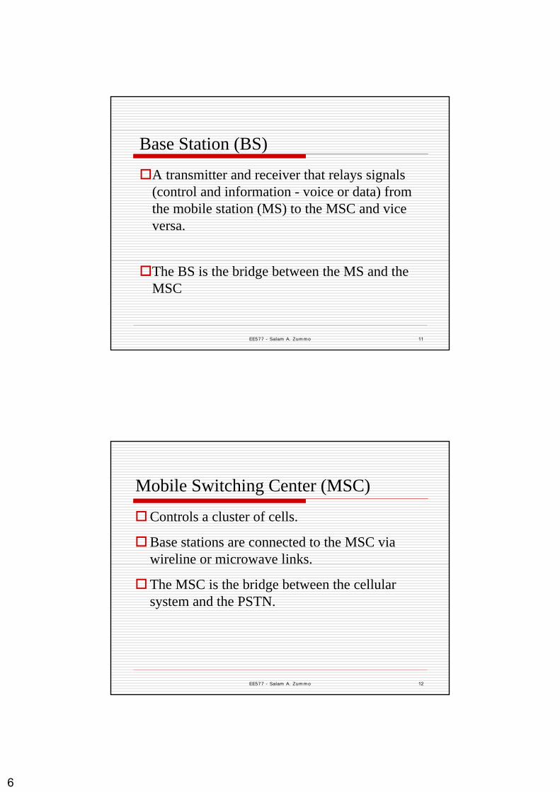
A transmitter and receiver that relays signals (control and information - voice or data) from the mobile station (MS) to the MSC and vice versa.
The BS is the bridge between the MS and the MSC
EE577 - Salam A. Zummo 12
Mobile Switching Center (MSC)
Controls a cluster of cells.
Base stations are connected to the MSC via wireline or microwave links.
The MSC is the bridge between the cellular system and the PSTN.

7
EE577 - Salam A. Zummo 13
Forward vs. Reverse Links
Forward Link (Downlink): The transmission path from the BS to the MS.
Reverse Link (Uplink): The transmission path from the MS to the BS.
EE577 - Salam A. Zummo 14
Sending and Receiving Types/Techniques
Types:Simplex: one-way communicationHalf-Duplex: two-way but one-way at a timeFull Duplex: two-way simultaneously
Techniques:Frequency Division Duplex (FDD)Time Division Duplex (TDD)

8
EE577 - Salam A. Zummo 15
FDD vs. TDD
EE577 - Salam A. Zummo 16
Basic Multiple Access Techniques
Used to simultaneously share a finite amount of the radio spectrum
Basic Types:Frequency Division Multiple Access (FDMA)Time Division Multiple Access (TDMA)Code Division Multiple Access (CDMA)
9
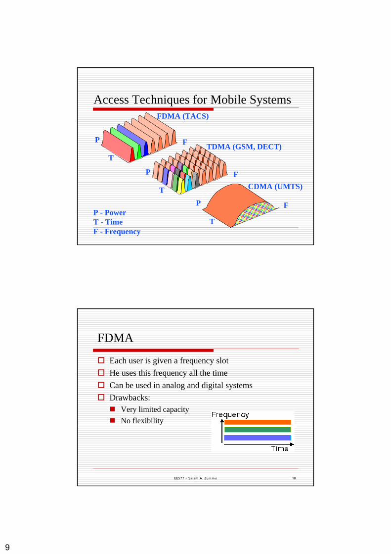
P - PowerT - TimeF - Frequency
P
T
P
T
F
P
T
F
FDMA (TACS)
TDMA (GSM, DECT)
CDMA (UMTS)
F
Access Techniques for Mobile Systems
EE577 - Salam A. Zummo 18
FDMA
Each user is given a frequency slotHe uses this frequency all the timeCan be used in analog and digital systemsDrawbacks:
Very limited capacityNo flexibility

10
EE577 - Salam A. Zummo 19
TDMAEach user is allocated a time slot. Can be used only in digital systems.Better capacity and more flexibility than FDMA
Drawbacks:SynchronizationHigher peak power > short battery lifeNeed for equalization for high data rate transmission (small bit duration)
EE577 - Salam A. Zummo 20
CDMAIt is a "spread spectrum" technology.All users share the same range of the radio spectrum.All user send at the same time over the same frequency band.Uses unique digital codes, rather than separate RF frequencies or channels to differentiate subscribers.The codes are called “Pseudo-Noise” (PN) code sequences.

11
EE577 - Salam A. Zummo 21
The Implications of Cellularity
Interference between re-used channels
Mobility management issuesLocating the users to initiate callsCall handover to maintain active calls.Management and billing issues.
EE577 - Salam A. Zummo 22
Handling the Interference Issue
Each transmitter (BS) is allocated a subset of the total available channels.Neighboring cells are allocated different sets of channels.Those sets of frequencies will be re-used only far enough to minimize interference level.This process is called frequency reuse or frequency planning.
12
EE577 - Salam A. Zummo 23
EE577 - Salam A. Zummo 24
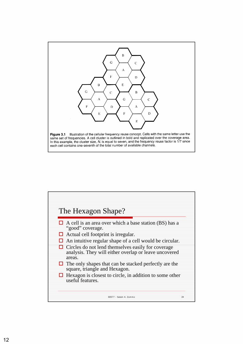
The Hexagon Shape?A cell is an area over which a base station (BS) has a “good” coverage. Actual cell footprint is irregular.An intuitive regular shape of a cell would be circular.Circles do not lend themselves easily for coverage analysis. They will either overlap or leave uncovered areas. The only shapes that can be stacked perfectly are the square, triangle and Hexagon.Hexagon is closest to circle, in addition to some other useful features.
13
EE577 - Salam A. Zummo 25
Cellular Definitions and NotationsCluster: set of neighboring cells that use the available channels distinctively and exhaustively.Co-channel cells: cells in different clusters that use the same group of frequencies.N = the cluster size (in cells)1/N = frequency re-use factor (Fraction of channels used by each cell).
R = cell radius (distance from hexagon center to corner).D = distance between centers of nearest co-channel cells.
EE577 - Salam A. Zummo 26
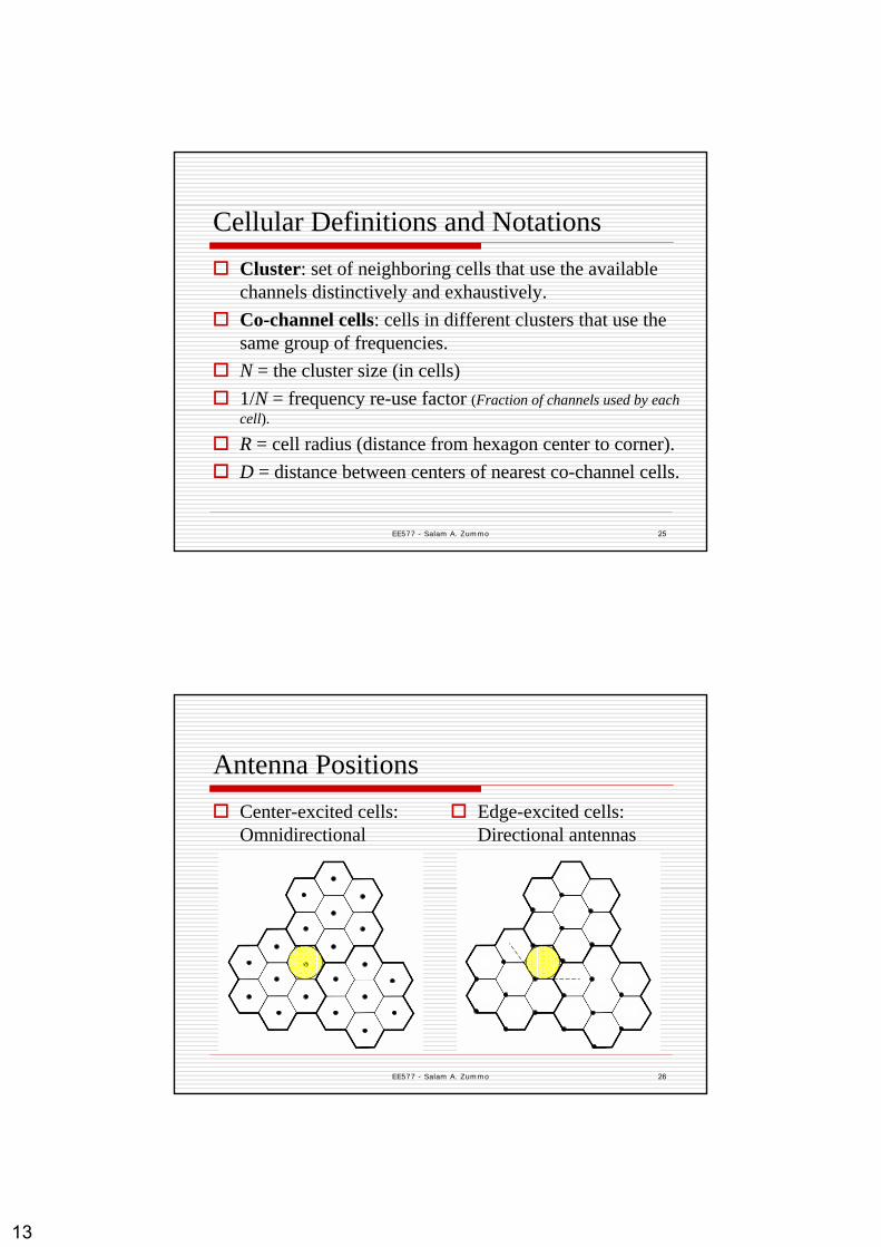
Antenna PositionsCenter-excited cells:Omnidirectionalantennas
Edge-excited cells:Directional antennas
14
EE577 - Salam A. Zummo 27
Cellular System Capacity Let the total number of channels available in the system be K, The number of clusters in the service area be M. Then:The system capacity C = M×K channels
Capacity = # possible simultaneous calls
EE577 - Salam A. Zummo 28
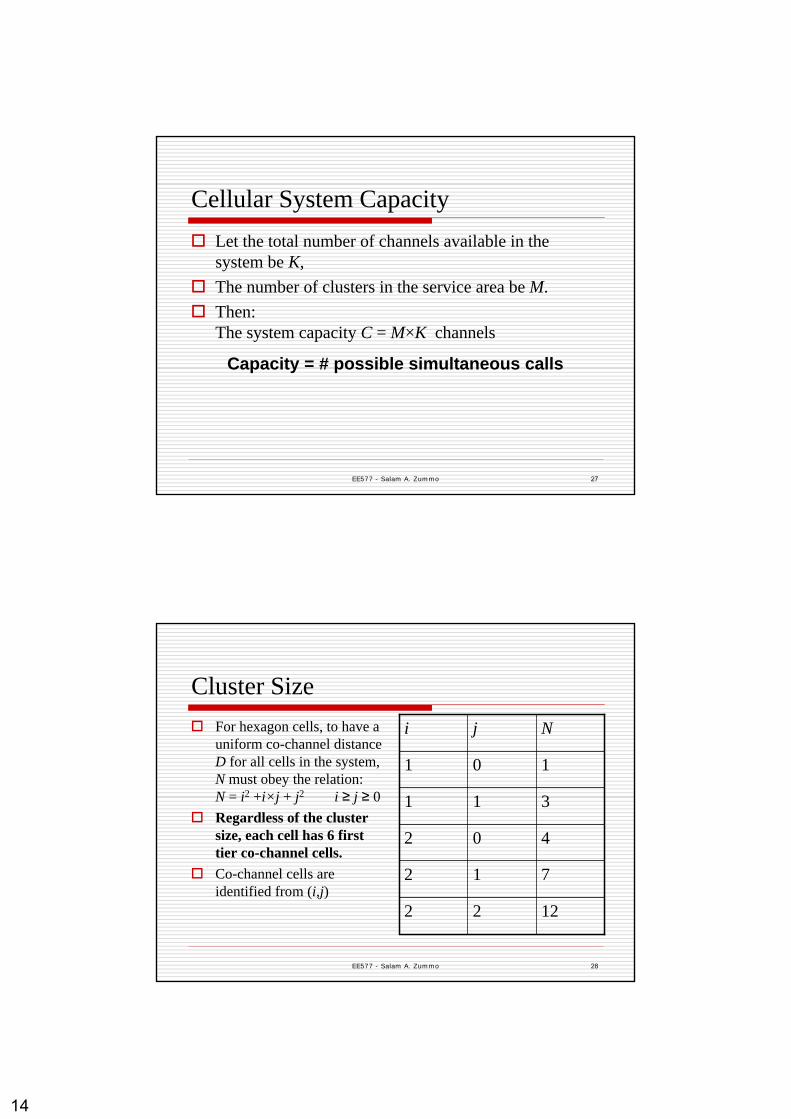
Cluster SizeFor hexagon cells, to have a uniform co-channel distance D for all cells in the system, N must obey the relation:N = i2 +i×j + j2 i ≥ j ≥ 0Regardless of the cluster size, each cell has 6 first tier co-channel cells.Co-channel cells are identified from (i,j)
712
1222
402
311
101
Nji

15
EE577 - Salam A. Zummo 29
Co-channel cells for N=7 (2,1) and N=19 (3,2)
EE577 - Salam A. Zummo 30
C is proportional to M (since S is constant)Small cluster size results in:
Larger capacity (larger M)Larger co-channel interference
Large cluster size results in:Smaller capacity (smaller M)Less co-channel interference
C is maximized by minimizing N

16
EE577 - Salam A. Zummo 31
Channel CategoriesVoice channels:Carry voice traffic (~ 95%)
Control channels:Carry data about call setup, handoff, power control and other management data (~ 5%)
EE577 - Salam A. Zummo 32
Example 1Determine the number of channels per cell for the following cellular system for N = 4 and N=7:
A total of 33 MHz bandwidth is allocated to the system.It is divided into 50-kHz (voice/control) channels. One control channel per cell.Frequency re-use factor of control channels is 3 times less than voice channels.
Solution:Total number of channels = 33000/50 = 660 N = 4:
12 channels reserved for control.Every cell has 648/4 = 162 voice channels and one control channel
N = 721 channels reserved for control639/7 = 91.3. Two cells have 92 + control, five have 91 + control.

17
EE577 - Salam A. Zummo 33
Channels Assignment StrategiesFixed Allocation: As in the previous example
SimpleLess efficient (higher blocking probability)Can be improved by implementing a borrowing strategy
Dynamic Allocation: All channels requested by MSC.Less blockageMore processing
EE577 - Salam A. Zummo 34
Dynamic Channel Assignment
MSC assigns a vacant channel to a BS upon requestTakes into account interference and frequency reuse distanceOffers higher overall capacity (smaller blocking probability)Harder to configure

18
EE577 - Salam A. Zummo 35
Channel Assignment in CDMA Systems
In CDMA systems the cluster size is N=1.A single 1.25 MHz channel carries the simultaneous transmission of a single control channel and up to 64 voice channels.In some ill-behaved propagation conditions a simple f1/f2 planning scheme is used:
Nearest neighbor cells use a frequency channel that is different from its closest neighbor in particularlocation/direction.
EE577 - Salam A. Zummo 36
HandoffPassing an active call from one BS to another without disconnection.
Basic concerns:When handoff is due?Where to handoff?How to handoff transparently?Management and billing
19
EE577 - Salam A. Zummo 37
Soft and Hard Handoffs
Hard Handoff:Handoff involves moving a call to another channel and another BS. (FDMA/TDMA systems)MS switches to a new channel after leaving the old one (The old BS drops the MS before the new one acquires it).
Soft Handoff:A call is moved to a different BS (CDMA).MS communicates with two BSs until handover is made.
EE577 - Salam A. Zummo 38
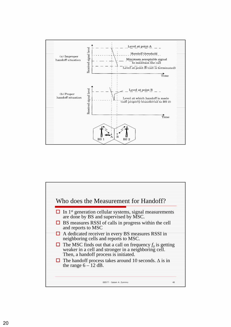
Handoff CriterionThe criterion for handoff is based primarily on the received signal level at the MS, Received Signal Strength Information (RSSI) (inferred from the reverse channel measurement).Two levels are defined: the minimum acceptable signal level to maintain a call, and the handoff threshold
Pr, handoff = Pr,minimum + ∆Optimum signal level for handoff initiation has to be designed
If ∆ is too large, unnecessary handoffs occurIf ∆ is too small, insufficient time to complete the handoff
Dwell time: the time over which a call may be maintained withouthandoff. It is a random time that depends on the motion of the user as well as motion in the environment.
20
EE577 - Salam A. Zummo 39
EE577 - Salam A. Zummo 40
Who does the Measurement for Handoff?In 1st generation cellular systems, signal measurements are done by BS and supervised by MSC. BS measures RSSI of calls in progress within the cell and reports to MSCA dedicated receiver in every BS measures RSSI in neighboring cells and reports to MSC.The MSC finds out that a call on frequency f0 is getting weaker in a cell and stronger in a neighboring cell. Then, a handoff process is initiated.The handoff process takes around 10 seconds. ∆ is in the range 6 – 12 dB.
21
EE577 - Salam A. Zummo 41
In 2nd Generation cellular systems, handoff decisions are mobile assisted (MAHO).Each MS measures received power from surrounding BSs and reports to the serving BS.A handoff is initiated if the power received for a neighboring BS exceeds the power received from the serving BS (i) by certain threshold or (ii) over certain period of time.MAHO systems are faster. The handoff process takes 1-2 seconds. ∆ is usually less than 6 dB.
EE577 - Salam A. Zummo 42
Prioritizing Handoffs
A fraction of total channels is reserved for handoff requests. (More efficient with dynamic channel assignment).
Queuing, with handoff requests given priority over new calls.

22
EE577 - Salam A. Zummo 43
Practical Issues: False Handoffs
Problem: Sometimes the drop in signal level is momentary (fading) and does not require handoff.
Solution: Monitor the signal level for some time to detect moving-away pattern. Averaging the measurements over some period may be useful as well.
EE577 - Salam A. Zummo 44
Practical Issues: High Speed UsersProblem:
frequent handoffs.Solution: Umbrella cell.
Large and Small cells co-located.High-speed users are served by umbrella cell, while slow users are served by the microcells.Sophisticated algorithms are used to evaluate and partition users according to their speeds
23
EE577 - Salam A. Zummo 45
Practical Issues: Cell DraggingProblem:
The signal stays strong even outside cell boarders.Creates potential interference and management problems.
Solution:Handoff thresholds and coverage parameters must be adjusted.
Note: Handoff is not required to rescue calls only. It is also required for proper overall system operation.
EE577 - Salam A. Zummo 46
Intra-system and Inter-system Handoffs Intra-system: A handoff between BSs that are controlled by the same MSC.Inter-system: A handoff between BSccontrolled by different MSCs.While Intra-system handoff are essential in any cellular system, Inter-system are not because they are not very frequent. It is acceptable that the call be disconnected while trans-crossing systems (or operators).

24
EE577 - Salam A. Zummo 47
InterferenceThere are many source of interference, but mainly two:
Co-channel Interference (from users in other cells operating at the same frequency)Adjacent-channel interference (from users within cell).
For voice channels, interference results in cross talk and background noise.For control channels, interference results in missed or blocked calls.
EE577 - Salam A. Zummo 48
Adjacent Channel Interference (ACI)Results from imperfect filters which allow nearby frequencies to leak into the working passband.Near-far effect, due to:
f1 and f2 being near in bandOne signal being orders of magnitude stronger than the other It results in f2 capturing the receiver of f1.
f1
f2
f1
f2

25
EE577 - Salam A. Zummo 49
Solutions to ACIFiltering: High quality filters.Channel assignment: Channels assigned to a cell are maximally separated.
Sequential assignment: Guarantees N channel separation.We can even prevent second tier interference by not assigning adjacent frequencies to adjacent cells (feasible for large N).More efficient when N is large.
Power Control:Reduces interferenceProlongs battery life.
EE577 - Salam A. Zummo 50
Co-Channel Interference (CCI) and Capacity
Assumption: All BSs transmit at the same power.Worst case analysis: CCI caused to a user on the edge of the cell.CCI is a decreasing function of Q = D/R (Co-channel reuse ratio)For a hexagon, Q = (3N)1/2
Small N small Q high CCISmall N large M high capacity

26
EE577 - Salam A. Zummo 51
Co-channel Reuse RatioIf Q is large, there is:
A lower interference level (co-channel cells are far apart since the cluster size is large)Smaller capacity
If Q is small, the system has:A higher interference level A larger capacity (since the cluster size is small)
System design needs to trade off capacity and interference levels
EE577 - Salam A. Zummo 52
Co-Channel Cells
i = 3, j = 2 => N = 19To find the co-channel cells:Move i cells along any directionRotate 60o counter-clock-wise and move j cells

27
EE577 - Salam A. Zummo 53
Interfering Cells
First-tier cells: The closest cells which use the same channels (1st-layer)
For simplicity we only take the first tier of cells into account for co-channel interference
2nd, 3rd, etc. tiers, cause negligible interference (larger distances)
EE577 - Salam A. Zummo 54
Model Assumptions
The signal strength has a power law decay with distance
Only relatively close co-channel cells will cause interference (io will be small)
The forward link power level is the source of the interference

28
EE577 - Salam A. Zummo 55
Rough SIR Calculations
S = Signal power from desired BSIi= CCI power from the ith co-channel BSi0 = the number of interferers
As a rough calculation
Pr = received power at distance d from transmitter.P0 = power at a reference point d0 from transmitter.n = path loss exponent
channel) (forward /0
1∑
=
== i
iiI
SISSIR
n
r ddPdP
−
⎟⎟⎠
⎞⎜⎜⎝
⎛=
00)(
EE577 - Salam A. Zummo 56
Substituting for S and I
Assuming same distance D from MS to the interferer BSs, and considering only first tier CCI (i0 = 6)
0
1∑
=
−
−
= i
i
ni
n
D
RSIR
( ) 6
3)/(
0
nn Ni
RDSIR ==
29
EE577 - Salam A. Zummo 57
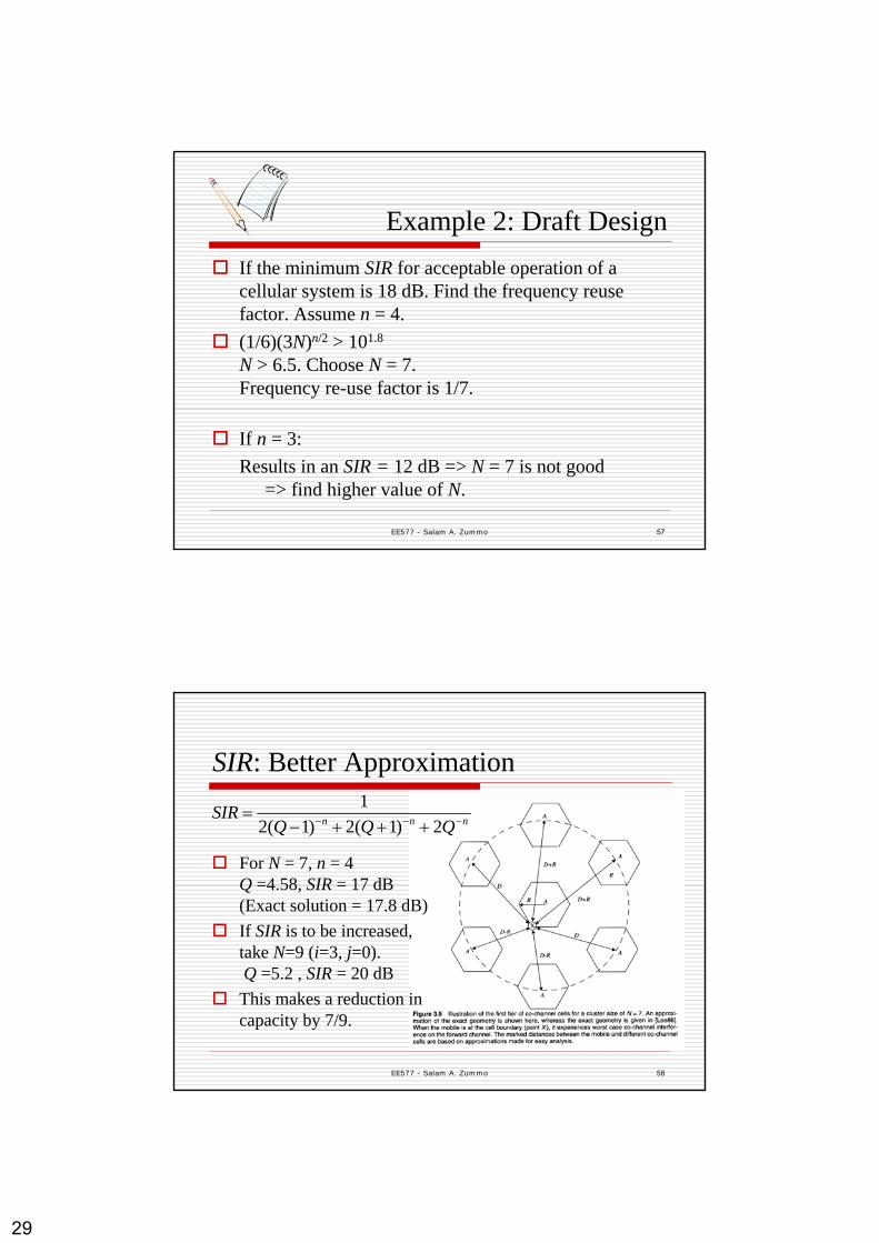
Example 2: Draft Design If the minimum SIR for acceptable operation of a cellular system is 18 dB. Find the frequency reuse factor. Assume n = 4.(1/6)(3N)n/2 > 101.8
N > 6.5. Choose N = 7.Frequency re-use factor is 1/7.
If n = 3: Results in an SIR = 12 dB => N = 7 is not good
=> find higher value of N.
EE577 - Salam A. Zummo 58
SIR: Better Approximation
nnn QQQSIR −−− +++−
=2)1(2)1(2
1
For N = 7, n = 4Q =4.58, SIR = 17 dB(Exact solution = 17.8 dB)If SIR is to be increased, take N=9 (i=3, j=0).Q =5.2 , SIR = 20 dBThis makes a reduction in capacity by 7/9.
30
EE577 - Salam A. Zummo 59
Frequency-reuse factor is set different for voice and control channelsControl channels are more vital Control channels are protected more from interference (high SIR and large Q)Voice channels are protected less (lower SIR and small Q)
Voice vs. Control Channels
EE577 - Salam A. Zummo 60
Interference in CDMA Systems
CCI interference is coming from other users in the same cell.The level of interference is a function of number of active users. The coverage range is dynamic/time varying
Breathing cell effect.Power levels and thresholds have to be adjusted according to the traffic intensity.
31
EE577 - Salam A. Zummo 61
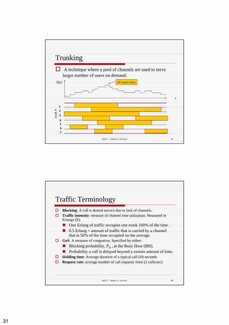
Trunking
N(t)
t
1234567
all trunks busy
trunk
#
A technique where a pool of channels are used to serve larger number of users on demand.
EE577 - Salam A. Zummo 62
Traffic Terminology Blocking: A call is denied service due to lack of channels.Traffic intensity: measure of channel time utilization. Measured in Erlangs (E).
One Erlang of traffic occupies one trunk 100% of the time .0.5 Erlang = amount of traffic that is carried by a channel that is 50% of the time occupied on the average.
GoS: A measure of congestion. Specified by either:Blocking probability, PB , at the Busy Hour (BH).Probability a call is delayed beyond a certain amount of time.
Holding time: Average duration of a typical call (H) seconds.Request rate: average number of call requests /time (λ calls/sec)
32
EE577 - Salam A. Zummo 63
Traffic Modeling Offered traffic = Aoffered = λ×HCarried Traffic = Acarried = {1- PB } × AofferedGeneral Assumptions:
Memoryless arrivals of requests Calls arrive according to Poisson Distribution
P[N(t)=k] = {(λt)k/k!}e-λt
Call duration follows an exponential distribution.Infinite number of users (or much greater than number of trunks)
EE577 - Salam A. Zummo 64
Models of Trunking SystemsBlocked Calls Cleared (BCC)
Erlang’s B Formula: probability a call is blockedPB= (AC/C!)/(∑C
k=0 Ak/k!) ;A=offered load at BH; C =# trunks
Blocked Calls Delayed (BCD)Erlang’s C formula: Prob. a call is queued.
PD [τ > t] = Pr [τ > 0]×Pr[τ > t|τ >0]= Pr [τ >0]×exp((A-C)t/H)
Average delay of all calls = Pr [τ >0]×(H/(C-A))
∑−
−+=> 1
0!/)/1(!
]0Pr[ CkC
C
kACACA
Aτ

33
EE577 - Salam A. Zummo 65
Erlang B Trunking GOS
EE577 - Salam A. Zummo 66
Blocking Probability Curves
offered load
# trunks
Blo
ckin
g Pr
obab
ility
34
EE577 - Salam A. Zummo 67
Example 3A cell has 19 channels. Find the number of users that can be supported at 2% blocking probability, if each user makes two calls per hour on the average, and the average call duration is 3 minutes.For GoS = 0.02 and C = 19 A = 12 E.Traffic intensity per user = 2×(3/60) = 0.1 ENumber of users supported in a cell = 120
EE577 - Salam A. Zummo 68
System Capacity
System capacity can be defined as:The maximum number of channels The maximum number of subscribers
35
EE577 - Salam A. Zummo 69
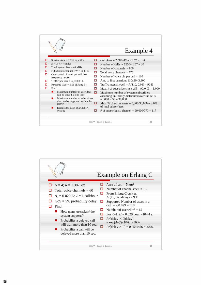
Example 4Service Area = 1,250 sq miles.N = 7; R = 4 milesTotal system BW = 40 MHzFull duplex channel BW = 50 kHzOne control channel per cell. No frequency re-use.Traffic per user = Au = 0.03 ERequired GoS = 0.01 (Erlang B) Find:
Maximum number of users that can be served at one time.Maximum number of subscribers that can be supported within this GOS?Discuss the case of a CDMA system
Cell Area = 2.589×R2 = 41.57 sq. mi.Number of cells = 1250/41.57 = 30Number of channels = 800Total voice channels = 770Number of voice ch. per cell = 110Ans. to first question: 110x30=3,300Traffic intensity/cell = A(110, 0.01) = 90 EMax. # of subscribers in a cell = 90/0.03 = 3,000Maximum number of system subscribers assuming uniformly distributed over the cells= 3000 × 30 = 90,000Max. % of active users = 3,300/90,000 = 3.6% of total subscribers. # of subscribers / channel = 90,000/770 = 117
EE577 - Salam A. Zummo 70
Example on Erlang CN = 4; R = 1.387 kmTotal voice channels = 60Au = 0.029 E; λ = 1 call/hourGoS = 5% probability delayFind:
How many users/km2 the system supports?Probability a delayed call will wait more than 10 sec.Probability a call will be delayed more than 10 sec.
Area of cell = 5 km2
Number of channels/cell = 15From Erlang C curves, A (15, %5 delay) = 9 ESupported Number of users in a cell = 9/0.029 = 310Number of users/km2 = 62For λ=1, H = 0.029 hour =104.4 s.Pr[delay >10|delay]= exp(A-C)×10/H)=56%Pr[delay >10] = 0.05×0.56 = 2.8%
36
EE577 - Salam A. Zummo 71
Trunk Utilization
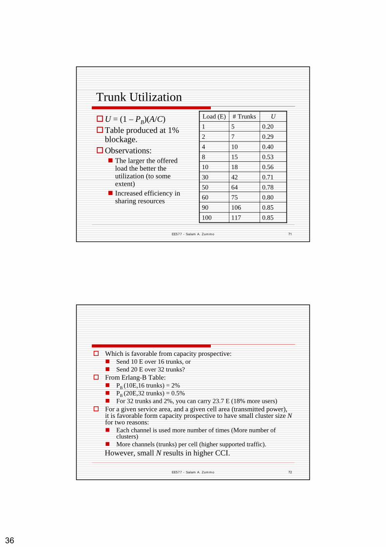
U = (1 – PB)(A/C)Table produced at 1% blockage.Observations:
The larger the offered load the better the utilization (to some extent)Increased efficiency in sharing resources
0.851171000.85106900.8075600.7864500.7142300.5618100.531580.401040.29720.2051
U# TrunksLoad (E)
EE577 - Salam A. Zummo 72
Which is favorable from capacity prospective:Send 10 E over 16 trunks, orSend 20 E over 32 trunks?
From Erlang-B Table:PB (10E,16 trunks) = 2%PB (20E,32 trunks) = 0.5%For 32 trunks and 2%, you can carry 23.7 E (18% more users)
For a given service area, and a given cell area (transmitted power), it is favorable form capacity prospective to have small cluster size Nfor two reasons:
Each channel is used more number of times (More number of clusters)More channels (trunks) per cell (higher supported traffic).
However, small N results in higher CCI.
37
EE577 - Salam A. Zummo 73
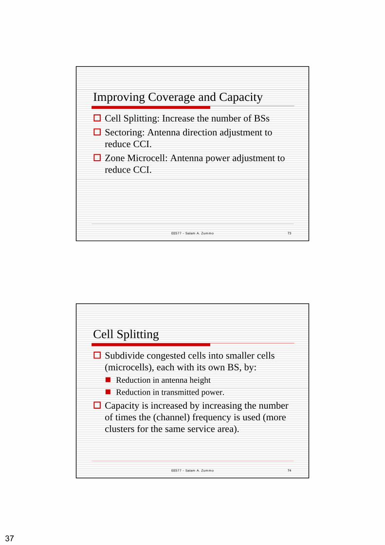
Improving Coverage and Capacity
Cell Splitting: Increase the number of BSsSectoring: Antenna direction adjustment to reduce CCI.Zone Microcell: Antenna power adjustment to reduce CCI.
EE577 - Salam A. Zummo 74
Cell Splitting
Subdivide congested cells into smaller cells (microcells), each with its own BS, by:
Reduction in antenna heightReduction in transmitted power.
Capacity is increased by increasing the number of times the (channel) frequency is used (more clusters for the same service area).

38
EE577 - Salam A. Zummo 75
EE577 - Salam A. Zummo 76
Both R and D are reduced at the same rate. Q is not changed. SIR not changed.Depending on the new designed cell radius, the transmitted power should be re-adjusted such that:Pr[at new cell boundary] = Pr[at old cell boundary]Pr is proportional to PtR-n
If the cell radius is reduced to αR, the transmitted power should be reduced by α nThat is Pt,2 / Pt,1 = α n
Example: R reduced by half, n=4 Pt,2 / Pt,1 = 1/16

39
EE577 - Salam A. Zummo 77
How much Capacity Enhancement is Achieved?
For reducing the radius by half, we are reducing cell area by 4; multiplying the number of clusters in the service area by 4.Therefore, capacity (number of channels) is quadrupled. At what cost?
Increasing the numbers of BSs (by a factor of 4).More handoffs (sophistication and processing)
EE577 - Salam A. Zummo 78
Different-cell-size SystemsNot all cells have (or need) to be split.In this case, different-size cells exists (different transmitter powers).Channel assignments becomes complicated.

40
EE577 - Salam A. Zummo 79
SectoringUsing directional antennas.Common sectoring patterns: 1200 and 600
The channels assigned to a cell are divided between the sectors.
EE577 - Salam A. Zummo 80
SectoringBy using directional antennas, we reduce the number of co-channel interferers.For 1200 sectoring, 1st tier interferers reduced from 6 to 2.
Improvement of 10log3 ≈ 5 dB(using better approx. ≈ 6.4 dB).60° sectoring reduces them by a factor of 6Improves SIR => can use small cluster size N => increase capacity
( ) 2
3)/(
0
nn Ni
RDSIR ==

41
EE577 - Salam A. Zummo 81
Illustration of Same CCI Scenarios
Omnidirectional Directional6 distant interferers 2 near interferers
A
B
C
D
A
B
C
D
B
C
D
A
B
C
D
B
A
B
C
A
EE577 - Salam A. Zummo 82
To achieve minimum SIR of 18 dB:
No Sectoring:Smallest cluster size is N = 12
120o Sectoring:Smallest cluster size is N = 7
=> 12/7 increase in capacity
Example
42
EE577 - Salam A. Zummo 83
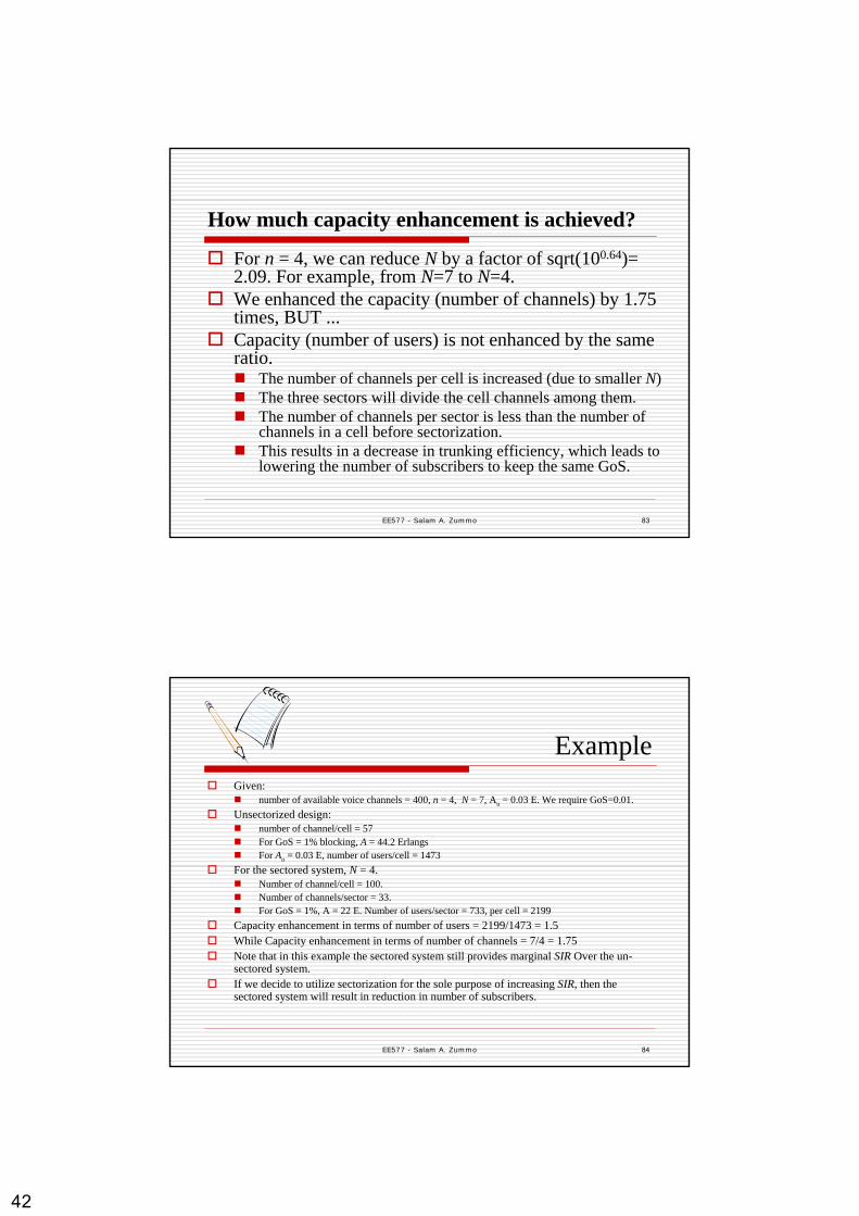
How much capacity enhancement is achieved?
For n = 4, we can reduce N by a factor of sqrt(100.64)= 2.09. For example, from N=7 to N=4.We enhanced the capacity (number of channels) by 1.75 times, BUT ...Capacity (number of users) is not enhanced by the same ratio.
The number of channels per cell is increased (due to smaller N) The three sectors will divide the cell channels among them.The number of channels per sector is less than the number of channels in a cell before sectorization.This results in a decrease in trunking efficiency, which leads to lowering the number of subscribers to keep the same GoS.
EE577 - Salam A. Zummo 84
ExampleGiven:
number of available voice channels = 400, n = 4, N = 7, Au = 0.03 E. We require GoS=0.01.Unsectorized design:
number of channel/cell = 57For GoS = 1% blocking, A = 44.2 ErlangsFor Au = 0.03 E, number of users/cell = 1473
For the sectored system, N = 4. Number of channel/cell = 100.Number of channels/sector = 33.For GoS = 1%, A = 22 E. Number of users/sector = 733, per cell = 2199
Capacity enhancement in terms of number of users = 2199/1473 = 1.5While Capacity enhancement in terms of number of channels = 7/4 = 1.75Note that in this example the sectored system still provides marginal SIR Over the un-sectored system.If we decide to utilize sectorization for the sole purpose of increasing SIR, then the sectored system will result in reduction in number of subscribers.

43
EE577 - Salam A. Zummo 85
Cell Sectoring: Pros and ConsAdvantages:
Improves the SIR of the system A gain of ~ 7 dB is achieved over omni-directional systems when 120° sectoring is used
Problems:Increased handoff requirements Multiple antennas are required in a BSDecreased trunking efficiency (less # channel per sector)
EE577 - Salam A. Zummo 86
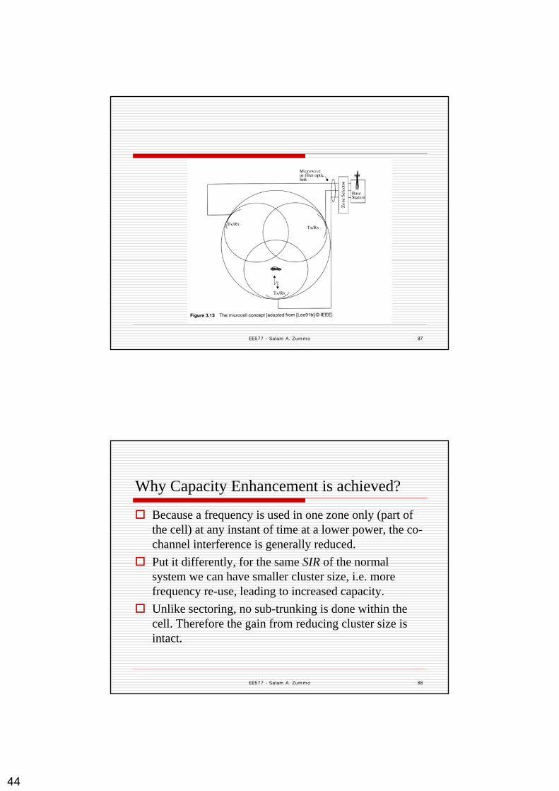
Microcell Zone ConceptThe high-power single cell transmitter is replaced by several lower power transmitters. Each transmitter defines a microcell.All microcell transmitters are connected to the cell BS (via fiber, coax, or microwave).A mobile in a cell is served by one zone at any instant of time.Cell channels are in a pool for all zones (no sub-trunking).Once a channel is assigned to a zone, it is not assigned to any other zone.A mobile user traveling from one zone to another in the cell retains the same frequency.Handoff is not required by MSC when crossing zones; the BS simply hands the mobile from one transmitter to the other without changing the frequency.
44
EE577 - Salam A. Zummo 87
EE577 - Salam A. Zummo 88
Why Capacity Enhancement is achieved?
Because a frequency is used in one zone only (part of the cell) at any instant of time at a lower power, the co-channel interference is generally reduced.Put it differently, for the same SIR of the normal system we can have smaller cluster size, i.e. more frequency re-use, leading to increased capacity.Unlike sectoring, no sub-trunking is done within the cell. Therefore the gain from reducing cluster size is intact.

45
EE577 - Salam A. Zummo 89
ExampleThe minimum required SIR for system operation is 18 dB.Consider a 7-cell structure.
Q = D / R = 4.6If we maintain Dz / Rz = 4.6, we maintain 18 dB.Let’s approximate circles by hexagons in the following skecth.
nnn QQQSIR −−− +++−
=2)1(2)1(2
1
EE577 - Salam A. Zummo 90
Rz =R/2For Dz/Rz = 4.6D/R ≈ 3 (show) So, N = 3N reduces from 7 to 3.Channel expansion= 7/3User Expansion = 7/3Cost: Smarter BSs.
46
EE577 - Salam A. Zummo 91
RepeatersUsed to extend coverage of a BS in covered or shadowed areasA repeater can be used for the whole spectrumDistributed Antenna System (DAS):
Provides directional coverage at input/output of a repeater (Rx/Tx)
Do not add capacity to systemUsually used in buildings
EE577 - Salam A. Zummo 92
Power ControlUse of power control is to reduce:
Power consumption => long battery lifeInterference => higher capacity
Both MS’s and BS’s operate at the lowest power level that will maintain an acceptable signal qualityVital for the operation of CDMA systemsDone through steps of power levelsTwo types: Open-loop and Closed-loop

47
EE577 - Salam A. Zummo 93
Open-Loop Power ControlDepends solely on MS; no feedback from BSBS continuously sends a pilot signal for phase and channel estimationMS monitors the received power levelMS adjusts its uplink power level accordinglyAssumption: uplink and downlink channels are highly correlatedNot as accurate as closed-loopQuick reaction to rapid signal fluctuationsEssential in CDMA systems to make received signals of users equal in power
EE577 - Salam A. Zummo 94
Closed-Loop Power ControlMS measures signal strength or quality and passes the information to the BS. BS decides on adjusting power levels based on different metrics such as:
Rx signal power level or Rx SNRRx bit error rate
BS sends command to MS via a control channel to adjust its powerlevelUsed in GSM with 8 power levelsMore accurateSlow and more complex to implement