
The CED 3505 V4 Owners Handbookced.co.uk/img/3505.pdf · 2014-10-29 · The CED 3505 Programmable...
29
The CED 3505 V4 Owners Handbook Copyright © Cambridge Electronic Design Limited 2010 Neither the whole nor any part of the information contained in, or the product described in, this guide may be adapted or reproduced in any material form except with the prior written approval of Cambridge Electronic Design Limited. 1 st edition (1.0) May 2010 2 nd edition (1.1) Nov 2010 Published by: Cambridge Electronic Design Limited Science Park Milton Road Cambridge CB4 0FE UK Telephone: +44 (0)1223 420186 USA & Canada Toll Free 1-800-345-7794 Fax: +44 (0)1223 420488 Web: www.ced.co.uk Email: [email protected] i
Transcript of The CED 3505 V4 Owners Handbookced.co.uk/img/3505.pdf · 2014-10-29 · The CED 3505 Programmable...

The CED 3505 V4 Owners Handbook Copyright © Cambridge Electronic Design Limited 2010 Neither the whole nor any part of the information contained in, or the product described in, this guide may be adapted or reproduced in any material form except with the prior written approval of Cambridge Electronic Design Limited. 1st edition (1.0) May 2010 2nd edition (1.1) Nov 2010 Published by: Cambridge Electronic Design Limited Science Park Milton Road Cambridge CB4 0FE UK Telephone: +44 (0)1223 420186 USA & Canada Toll Free 1-800-345-7794 Fax: +44 (0)1223 420488 Web: www.ced.co.uk Email: [email protected]
i

Index
ii
Trademarks and Tradenames used in this guide are acknowledged to be the Trademarks and Tradenames of their respective Companies and Corporations.

Table of Contents
iii
Preface Publishing information ................................................................ i Table of contents ....................................................................... iii Potential for Radio/Television interference .............................. iv Use of symbols ........................................................................... v Life support ................................................................................ v
The CED 3505 Programmable
Attenuator
Introduction ................................................................................ 1 Attenuation stages ...................................................................... 4 Pulse out BNC ............................................................................ 4 Headphone drive output ............................................................. 5 Attenuation settings via parallel control..................................... 6 Parallel control connections ....................................................... 6 Programming example................................................................ 7
CED 3505 commands
Serial control instructions........................................................... 8 Serial command list .................................................................... 9
Maintenance Firmware updates ..................................................................... 18 Rear-panel switch pack ............................................................ 18 Power connector ....................................................................... 19 CED 3505 safety information and cleaning instructions ......... 19 CED 3505 environmental considerations................................. 19
Index Index ......................................................................................... 20 User notes ................................................................................. 21
EC Declaration of Conformity
EC Declaration of Conformity ................................................. 23

Table of contents
iv
The CED 3505 generates and uses radio frequency energy and may cause interference to radio and television reception. Your CED 3505 complies with the Specification in Subpart J of Part 15 of the Federal Communications rules for a Class A computing device. These specifications provide reasonable protection against such interference in a residential installation. However there is no guarantee that interference will not occur in a particular installation. If the CED 3505 does cause interference to radio or television reception, which can be determined by turning the CED 3505 mains supply off and on, you can try to eliminate the interference problem by doing one or more of the following:
Potential for Radio/Television
Interference (USA only)
• Re-orient the receiving antenna • Re-orient the position of the CED 3505 with respect to the
receiver • Move the CED 3505 away from the receiver • Plug the CED 3505 into a different outlet so that the
CED 3505 and the receiver are on different branch circuits
If necessary, consult CED or an experienced radio/television technician for additional suggestions. You may find the booklet, prepared by the Federal Communications Commission, helpful: How to Identify and Resolve Radio/TV Interference Problems. The booklet is available from the US Government Printing Office, Washington DC 20402, Stock no. 004-000-00345-4.
To comply with FCC rules, Part 15 B Class A Computing device, use only shielded interface cables.
Table of Contents
Use of symbols Where applied, the following symbols have the meanings below:
This symbol declares that the equipment passes the relevant clauses of EU directives on safety and EMC emissions; see the certificate reproduced on page 23
The CED 3505 Programmable Attenuator is lead-free and conforms to the EU RoHS directive
The CED 3505 Programmable Attenuator is subject to the EU WEEE regulations and may be returned to CED Ltd for recycling
Attention, consult accompanying documents
The DC symbol indicates that the CED 3505 Programmable Attenuator chassis is powered from a DC-only supply
Life support CED products are not authorized for use as critical components in life support systems without the express written approval of the chairman of the board of directors of CED.
Life support systems in this context are systems which support or sustain life, and whose failure to perform, when properly used in accordance with instructions for use provided, can be reasonably expected to result in a significant injury to the user. A critical component in this context is any component of a life support system whose failure to perform can reasonably be expected to cause the failure of the life support system, or to affect its safety or effectiveness.
v

The CED 3505 Programmable Attenuator
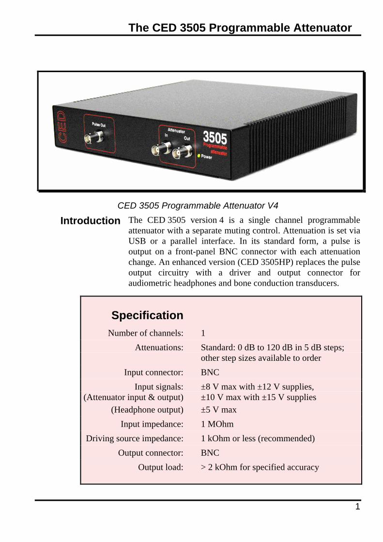
CED 3505 Programmable Attenuator V4
Introduction The CED 3505 version 4 is a single channel programmable attenuator with a separate muting control. Attenuation is set via USB or a parallel interface. In its standard form, a pulse is output on a front-panel BNC connector with each attenuation change. An enhanced version (CED 3505HP) replaces the pulse output circuitry with a driver and output connector for audiometric headphones and bone conduction transducers.
Specification Number of channels: 1 Attenuations: Standard: 0 dB to 120 dB in 5 dB steps; other step sizes available to order Input connector: BNC Input signals: ±8 V max with ±12 V supplies, (Attenuator input & output) ±10 V max with ±15 V supplies (Headphone output) ±5 V max Input impedance: 1 MOhm Driving source impedance: 1 kOhm or less (recommended) Output connector: BNC Output load: > 2 kOhm for specified accuracy
1

The CED 3505 Programmable Attenuator
2
Frequency response: DC - 100 kHz (−3 dB) when no filter fitted Filter option: 4th-order low-pass Filter frequency: 40 kHz (standard); other frequencies to special order Filter characteristic: Butterworth (standard), Bessel, or sinc- compensated Butterworth (special order) Attenuation accuracy: ±0.2 dB 10 Hz - 20 kHz
Mute: Greater of attenuation set and −70 dB, DC - 20 kHz Output offset: < 0.5 mV, all attenuations
Pulse out: 5 V TTL, approx. 2 µs length, (standard 3505 only) selectable polarity Headphone output: Drive for audiometric headphones, (3505HP only) ≥10 Ohm, each ear muteable Headphone connector: 6.35 mm TRS jack socket (3505HP only) Headphone calibration: Separate L + R headphone calibration attenuators 0 - 24 dB, 0.4 dB resolution Parallel control: 7-bit parallel 5 V TTL on 25-way D-plug; 8 mA load to ground per line Control cable (option): 2 m terminating in 25-way D-socket for CED 1401 digital output Serial control: USB virtual serial port at 9600 baud Power required: ±12 to ±15 V DC 50 mA (standard 3505) 800 mA (3505HP, headphones driven) Power supply: CED type B15, 100 - 240 V AC mains input 50 - 60 Hz, ±15 V DC output
Case size: 240 mm x 240 mm x 46 mm (W × D × H) excluding connectors and power supply Weight: 3 kg including mains power supply

The CED 3505 Programmable Attenuator
5V TTL 2 microsecond pulse out on attenuation change command [p4] Attenuator outputAttenuator input
Power/ error LED
CED 3505 front panel
Reset push button [p18]
Parallel control port [p6]
D.C. power inlet connector [p19]
Serial number, CE and WEEE markings [p19]
Options switch [p18]
USB inlet[p7]
CED 3505 rear panel
3

The CED 3505 Programmable Attenuator
Attenuation stages
The CED 3505 V4 has two cascaded stages of attenuation, plus a muting position. The standard-build first stage has six steps of 20 dB, giving 0 dB to 120 dB of attenuation. The standard second stage has four steps of 5 dB, giving 0 dB to 15 dB of attenuation. Other attenuation steps are available to order.
The CED 3505 attenuator can be supplied with a 4-pole low-pass filter fitted. The cut-off frequency is specified by the user at time of order and can be in the range 5 kHz to 50 kHz. A Butterworth characteristic is standard, but optionally may be specified to be either Bessel or a modified Butterworth characteristic that incorporates an approximation to an inverse sinc (x/sin x) for correction of DAC output frequency responses in applications where a fixed update sampling rate is used. If the output filter is not fitted, the attenuator frequency response extends to 100 kHz or higher. The ?FF command can be used to check the cut-off frequency of a CED 3505. The frequency is returned as a number in kHz, or as 0 if no filter is fitted.
Filter option
Pulse out BNC (standard
CED 3505 only)
The BNC connector on the CED 3505 front panel outputs a pulse whenever the attenuation setting is updated from the serial line, even if the same attenuation value is written as is currently set. If a new attenuation value is sent when the CED 3505 output is muted, generation of the pulse is delayed until the mute is cancelled. The pulse is 5 V TTL compatible, and the polarity can be set using the OP1x serial line command. The output can drive 2 mA to a high or low level. In addition, the serial line PO command can be used to generate a single pulse at this output independent of the mute state.
4

The CED 3505 Programmable Attenuator
Headphone drive output
(CED 3505HP only)
The CED 3505HP, the enhanced model of the version 4 attenuator, is fitted with an audiometric headphone drive circuit and 6.35 mm jack socket in place of the pulse output connector. The socket is wired: tip = left channel, ring = right channel, sleeve = return (ground). The jack plug should always be fully inserted or else completely out: partial insertion can cause shorts between the conductors.
The headphone drive circuitry has a number of features designed for single-voiced audiometric applications.
• Two-channel power amplifier suitable for driving audiometric headphones and bone conduction transducers having an impedance of 10 Ohms or greater
• AC coupled low-frequency response at approximately 20 Hz • Servo circuit to null the DC offset on the headphone outputs
on each channel • Individual muting controls for L and R channels • Individual calibration attenuators with approximately 0.4 dB
step size on each of the L and R channels, software settable to correct for known deviations in the headphone response from the nominal values
• Overall global headphone mute without affecting other settings
• Sound pressure levels in excess of 130 dB achievable with standard THD49 headphones
Version 4 of the CED 3505 has additional main attenuation settings compared with previous versions. Software using the USB should interrogate the attenuator version number before issuing commands that are new or changed in CED 3505 V4.
Software compatibility with previous versions
The parallel input now uses bits 5 - 0 as attenuation control and bit 6 as a mute. Software that controlled previous versions via the parallel input will need minor alterations to accommodate these changes.
5
The CED 3505 Programmable Attenuator
Attenuation settings via
parallel control
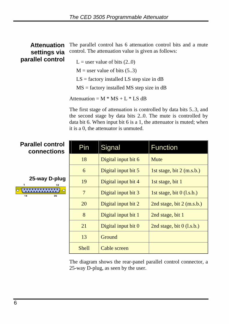
The parallel control has 6 attenuation control bits and a mute control. The attenuation value is given as follows:
L = user value of bits (2..0) M = user value of bits (5..3) LS = factory installed LS step size in dB MS = factory installed MS step size in dB
Attenuation = M * MS + L * LS dB
The first stage of attenuation is controlled by data bits 5..3, and the second stage by data bits 2..0. The mute is controlled by data bit 6. When input bit 6 is a 1, the attenuator is muted; when it is a 0, the attenuator is unmuted.
Parallel control connections Pin Signal Function
18 Digital input bit 6 Mute
6 Digital input bit 5 1st stage, bit 2 (m.s.b.)
19 Digital input bit 4 1st stage, bit 1
7 Digital input bit 3 1st stage, bit 0 (l.s.b.)
20 Digital input bit 2 2nd stage, bit 2 (m.s.b.)
8 Digital input bit 1 2nd stage, bit 1
21 Digital input bit 0 2nd stage, bit 0 (l.s.b.)
13 Ground
Shell Cable screen
25-way D-plug
The diagram shows the rear-panel parallel control connector, a 25-way D-plug, as seen by the user.
6

The CED 3505 Programmable Attenuator
Programming example
The CED 3505 V4 parallel interface connects to the low byte of a CED 1401 digital output. When using CED Spike2 or CED Signal software, the CED 3505 is conveniently controlled using the digital sequencer’s DIGLOW instructions:
LABEL: DIGLOW [.1......] set mute bit without changing the attenuation
DIGLOW [..xxxxxx] leave mute bit set and load new attenuation data xxxxxx
Parallel control from CED Spike2
and Signal software
DIGLOW [.0......] clear mute bit and activate new attenuation setting
As an alternative to using the parallel control input, the CED 3505 Version 4 can be controlled via ASCII command strings sent to a USB virtual COM port (9600 baud, 1 stop bit, no parity). It will function correctly on USB 2.0 as well as USB 1.0 ports, but it is not recommended that the CED 3505 be connected to a USB 2.0 hub along with other devices that require USB 2.0 high-speed operation. Depending on the operating system in use, a driver may be needed to implement the computer end of the virtual COM port. You should select the driver appropriate for your operating system from the FT232BM VP drivers available on the FTDI website: www.ftdichip.com.
Control via a virtual serial port
Connecting a USB cable from a powered-up computer to the CED 3505 enables the USB virtual serial port. Parallel port control operation remains active, but the USB commands have no knowledge of any attenuations set by the parallel port.
Hot plugging
The CED 3505 has an option to set XON/XOFF flow control protocol for the virtual serial port.
7

CED 3505 commands
Serial control instructions
A set of simple ASCII commands is used to control and interrogate the CED 3505. The general format of a command takes one of two forms: a set form and a query form. The query form begins with a question mark. The command itself consists of two alphabetic characters followed (where appropriate) by alphanumeric arguments. A command is terminated either by a semicolon or a <cr> (carriage return) character.
Set form: XYn; or XYn<cr>
Query form: ?XY; or ?XY<cr>
Response: mm<cr> or mm<cr><lf>
where XY is the command, n is one or more concatenated arguments and mm is the response appropriate to the query form of the command. Some commands take an argument n in the query form.
The EC command controls whether the received characters are echoed back to the controlling computer and also whether <lf> (line feed) is appended to the <cr> that terminates returned values.
The EC command
The CED 3505 handles numeric quantities as unsigned decimal integers by default, but this may be changed to be hexadecimal by the use of the OP01 command. In decimal mode only, some commands accept or return a decimal point followed by a single further digit after the integer part of the value.
Numeric quantities
An invalid or malformed command will generate an error and set the front panel LED red. The error is stored by the CED 3505 until an ?ER; command is received, when the error code will be reported and the LED returned to green. Only one level of error is stored, so new errors will be lost if a previous error has not been interrogated.
Errors
8

CED 3505 commands
9
Serial command list for CED 3505
version 4
Format Description
ATn; ATn.m;
?AT; n.m
Set attenuation
Read attenuation
Sets or reads the attenuation in positive values of dB. The parameter n is an integer number in the range zero to the installed maximum, and is optionally followed by a decimal point and a single decimal digit m. The attenuation value will be rounded down (less attenuation) to the nearest multiple of the least significant CED3505 attenuation step.
The query form returns in dB the last attenuation actually used (which may be a rounded or limited value), independent of whether the output is currently muted.
A pulse is generated at the pulse output BNC connector by the set form of the AT command (and also by the PO command). If the attenuator output was in the muted state when issuing the AT command, the attenuation will be set to the new value but the output will remain muted; the pulse will be generated on un-muting to show that a new attenuation value is in operation. The pulse is not available on CED3505HP models.
?AS; ms ls mn ln
Read attenuation step sizes and number of steps
Reads the attenuation step sizes in dB and numbers of steps for this unit
The order in which the values are returned is: MS step size, LS step size, MS number of steps, LS number of steps. The LS step size may be returned as n.m if it is non-integral

CED 3505 commands
10
ASv; The set form of the command allows the attenuation step sizes and numbers of steps to be set and stored in CED 3505 EEPROM during manufacture. Once these are set, the AS command cannot change them, and attempts to use the set form will give an error. The order of setting is the same as for ?AS, but note that only in this setting form of the AS command the ls step must be given in centiBels (10 times the dB value).
MUn;
?MU; n
Mute the output
Read the mute state
MU1 mutes the output; MU0 unmutes. Query form returns n as 1 (muted) or 0 (unmuted)
HSn;
?HS; n
Select headphone for calibrating or muting (CED 3505HP only)
HS0 deselect both headphones
HS1 select left headphone and deselect right headphone
HS2 select right headphone and deselect left headphone
HS3 select both headphones
Read back the last legal setting

CED 3505 commands
11
HAn.m;
?HA; nl nr
Set the calibration attenuators on one or both headphone (as selected by HS) in range 0.0 to 24.9 dB. The hardware resolution is approximately 0.4 dB, and the requested value will be rounded to the next greater available attenuation
Read back the actual attenuations in dB currently set. Two values (L and R channels) are returned in the form xx.x, independent of HS selection
HMn;
?HM; n
Set or clear the mutes on selected headphones (CED 3505HP only)
HM0 clear all headphone mutes
HM1 set individual headphone mute
HM2 clear individual headphone mute
HM3 set global headphone mute
HM4 clear global headphone mute
Read back the mute state. Set if muted
Bit 0 L Bit 1 R Bit 2 global mute
PO; Pulse the output BNC connector (CED3505 only). The 2 microsecond pulse will have the polarity set in the CED3505 EEPROM (see OP command description). Examples of use of this command could be to trigger an averager or for checking the time it takes to send serial commands from a script to the CED3505. The PO command has no effect in the CED3505HP

CED 3505 commands
12
?ER; n Interrogate error status
Returns a string in the format xyz, where xy is the command that generated the error and z is the error logged. Interrogating the error status clears any error logged. If no error has been logged since this command was last called, the command will return 000. Once an error has been logged, any further errors that occur will not be logged, so the error status should be checked on a regular basis to ensure errors are not missed
If the first two characters in the command string did not match a valid command, an ‘Unknown Command’ error will be logged and z will be set to ‘U’
If there were no alphabetic characters at the start of the string, xy will be returned as ‘--’, or ‘x-’ if there was a single alphabetic character.
If the format of a parameter in a command sent to the CED 3505 was not valid, or there was a parameter supplied unexpectedly with a query form, an ‘Illegal Parameter’ error will be logged and z will be set to ‘I’
?FF; n
FFv;
Interrogate the analogue filter frequency. n is returned in kHz, or as 0 if no filter fitted
The set form of the command allows the filter frequency to be set and stored in CED 3505 EEPROM during manufacture. Once a frequency is set, the FF command cannot change it, and attempts to set it will give an error

CED 3505 commands
13
ECn;
?EC; n
Echo Character and Line Feed control
Allows the user to select whether characters received by the unit are echoed to the PC
n = 0 (default) no echo, no LF appended; n = 1 echo all characters received; n = 2 append LF to CR; n = 3 echo characters and append LF
SCn;
?SC; c
Synchronizing Character
The synchronizing character defaults to <cr> on reset and can be altered by writing the numerical ASCII value n of any character c. If the synchronizing character is not <cr>, the query form of this command returns the single synchronizing character followed by <cr>
?SN; n
SNssss
Read Serial Number
Returns a string in the format ‘PAxyyy’. It represents the serial number of the unit, where x is the major hardware revision, a decimal integer in the range 1 - 9, and yyy is the serial number of the unit, a decimal integer in the range 001 - 999
The set form of the command allows the serial number string to be set and stored in CED 3505 EEPROM during manufacture. Once a serial number is set, the SN command cannot change it, and attempts to set it will give an error

CED 3505 commands
14
?VS;
?VSb;
Read software version
Dump memory bank b (debug only)
?VS; returns a string in the form 00 representing the current revision of the microprocessor firmware in the CED 3505
?VSb; (b in range 0 to 3) dumps memory bank b and I/O ports as hexadecimal bytes
?SW; Read Switch Value
Returns the setting of the rear-panel DIP switch in the range 0 - 15 or 00 - 0F
OPnv;
?OPn; v
Option set / read
n in range 0 - 7, v is 0 or 1. The options are stored in EEPROM inside the CED 3505, so need to be set only once according to the user’s requirements
n = 0 v = 0 (default) set decimal i/o v = 1 set hexadecimal i/o
n = 1 v = 0 (default) BNC output pulse low- going v = 1 pulse high-going
n = 2 v = 0 (default) no serial line flow control v = 1 use XON/XOFF
Other values of n are reserved and may have unpredictable results if used

CED 3505 commands
15
SUxx;
SU00;
?SU;
Set / clear / read start-up string
The CED 3505 can store a string of commands to be interpreted on start-up, as though they had been sent from the serial line. This allows the unit to be programmed via a serial line and then used stand-alone, i.e. without the serial line connected. The start-up string can contain up to 32 characters. Care must be taken only to use commands in the start-up string that are appropriate for stand-alone use, as the string is not checked for sense
The non-volatile memory in the CED 3505 can be written only a finite number of times before its long-term storage ability is impaired. Although this number is large (>1000 string stores), the SU command should be used sparingly
In order to avoid the CED 3505 interpreting the characters during the setting up of the start-up string, the SUxx command requires the character values to be sent one at a time as the hexadecimal value of the character. Only two-digit character values for xx in the hexadecimal range 20 (Space) to 7E (“~”) are accepted. A delay of about 100 ms is needed after each character loaded to allow time for the EEPROM write and recovery
The query form of the command echoes the stored start-up string to the computer in its ASCII stored form
The command SU00; is a special case that has the effect of zeroing the stored string. Used on its own, it restores the CED 3505 to the state before a startup string was loaded
CED 3505 commands
16
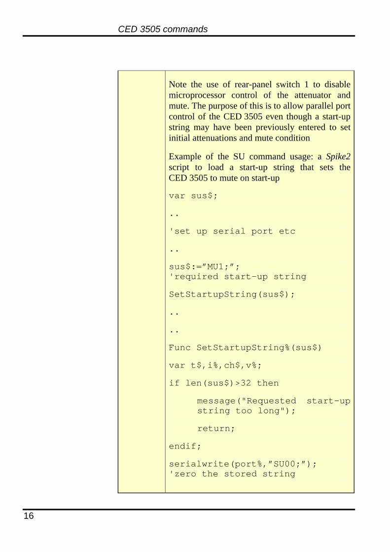
Note the use of rear-panel switch 1 to disable microprocessor control of the attenuator and mute. The purpose of this is to allow parallel port control of the CED 3505 even though a start-up string may have been previously entered to set initial attenuations and mute condition
Example of the SU command usage: a Spike2 script to load a start-up string that sets the CED 3505 to mute on start-up
var sus$;
..
'set up serial port etc
..
sus$:=”MU1;”; 'required start-up string
SetStartupString(sus$);
..
..
Func SetStartupString%(sus$)
var t$,i%,ch$,v%;
if len(sus$)>32 then
message("Requested start-up string too long");
return;
endif;
serialwrite(port%,”SU00;”); 'zero the stored string

CED 3505 commands
17
yield(.1); 'allow time for EEPROM write
for i%:=1 to len(sus$) do
ch$:=mid$(sus$,i%,1); 'get next char from string
v%:=asc(ch$); 'form numerical value of char
t$:=print$("su%02x;",v%); 'form command with hex value
serialwrite(port%,t$); 'send to CED 3505
yield(.1); 'allow time for EEPROM write
next;
return;
end;

Maintenance
Firmware updates
From time to time, CED may issue updated firmware for the CED 3505 in the form of a zip file containing the new firmware and a boot loader (PICbootPlus.exe). The firmware is updated via the USB virtual serial port. After unzipping the files, make sure power is applied to the CED 3505 and that the USB cable is connected, then run the boot loader and select the appropriate serial port at a rate of 19200 (n.b. not 9600 for firmware updates). Navigate to the directory containing the new firmware file, check the EEPROM button in the loader window and click WRITE. Use a small circular stylus to push and release the recessed RESET button located on the CED 3505 rear panel. The firmware loading will commence and will take about 20 seconds. After completion, close the boot loader program and switch off the CED 3505. On re-applying power, the CED 3505 will be ready with updated firmware. The version can be checked through the use of the ?VS command.
Rear panel switch pack
The pattern set on this switch pack is sampled only on powering up the CED 3505 attenuator.
Switch Function 1 0 = normal;
1 = disable microprocessor control of attenuation and mute settings
2 Reserved
3 Reserved
4 Reserved
4-way piano- key switch
18

Maintenance
Power connector The rear-panel power inlet connector is a 5-pin DIN socket.
Pin Usage 1 No connection
2 0 V
3 No connection
4 – 15 V
5 + 15 V
Shell Chassis earth
5-way 180° DIN socket
Use only the power supply furnished by CED with the CED 3505 Version 4
•
•
•
•
•
• • •
CED 3505 safety information
and cleaning instructions
There is no power switch on the CED 3505. To remove power from the unit, disconnect the mains to the power supply. Operate the CED 3505 in conditions of non-condensing humidity at an ambient temperature below 50 ºC. The CED 3505 case is not resistant to the ingress of water or other fluids. There are no user serviceable parts inside the CED 3505 case. The CED 3505 is suitable for continuous use. Clean only with a dry cloth when required.
DO NOT immerse in water or any other chemical solution.
CED 3505 environmental considerations
The case and components within the CED 3505 are recyclable. Please consult the manufacturer for details when required.
The CED 3505 is lead-free and conforms to the EU RoHS directive.
19

Index
A AC coupling, 5 ASCII commands, 8 Attenuation control bits, 6 Attenuation stages, 4
B Bias current, 1 BNC connector, 4, 9
C Cable
Digital output, 2 USB, 18
Calibration attenuators, 5 Case dimensions & weight, 2 CED’s address, 23 CED’s telephone numbers, i Command
?AS, 9 ?ER, 8, 12 ?FF, 12 ?SN, 13 ?VS, 14, 18 AT, 9 EC, 8, 13 HA, 11 HM, 11 HS, 10 MU, 10 OP, 14 PO, 11 SC, 13 SU, 15
Command format, 8
D DC offset nulling, 5 Declaration of Conformity,
23 DIGLOW, 7 D-plug connections, 6
F Filter, 2, 4 Filters
mains notch, 1 Firmware updates, 18 Frequency response, 4 Front panel (picture), 3
G Gain range, 1
H Headphone mute, 5 Headphone output, 2, 5 Host data cable, iii
I Ingress of water, 19 Input impedance
main amplifier, 1 Input range, 1 Invalid command, 8
L LEDs, Overload, 1 Life support, iv
N Numeric quantities, 8
O Output offset, 2 Overload indicators, 1
P Power amplifier, 5 Power input, 19 Power supply, 2 Pulse output, 4
delayed if muted, 4
R Rear panel (picture), 3 Rear-panel switch pack, 18 Recycling CED 3505, 19 Reset button, 18
S Serial control, 2 Signal, 7 Spike2, 7
U USB virtual COM port, 7
V Version 4, 5 Version number, 5
X XON/XOFF, 7
20

User notes
21

User notes
22

EC Declaration of Conformity This is to certify that the:
CED 3505 Manufactured by:
Cambridge Electronic Design Limited Science Park, Milton Road, Cambridge CB4 0FE, UK
Tel (+44) 01223 420186
Conforms with the protection requirements of Council Directive 2004/108/EC, relating to Electromagnetic Compatibility,
by the application of the following EMC standards:
Conducted and radiated emissions:
EN55022 (1987) Class B - COMPLIES Vfg1046/1984 - COMPLIES FCC CFR47 Part 15 Subpart J Class A - COMPLIES
EN50082-1:1991 Immunity standards:
EN50082-1 (Generic immunity) - PASS EIC801-2 (Electrostatic discharge) - PASS (8kV) Criterion A EIC801-3 (RF field immunity) - PASS (3V/m) Criterion B
EIC801-4 (Electrical fast transients) - PASS (2kV - Heavy industrial) Criterion A
Signature
Date
Peter Rice Technical Director 20 July 2009