The Catalytic Hydrogenation of Aromatic Nitro Ketone in a Microreactor: Reactor Performance and...
40
I NTERNATIONAL J OURNAL OF C HEMICAL R EACTOR E NGINEERING Volume 6 2008 Article A112 The Catalytic Hydrogenation of Aromatic Nitro Ketone in a Microreactor: Reactor Performance and Kinetic Studies Sunitha Tadepalli * Adeniyi Lawal † * Stevens Institute of Technology, [email protected] † Stevens Institute of Technology, [email protected] ISSN 1542-6580 Brought to you by | York University Libraries Authenticated | 10.248.254.158 Download Date | 8/12/14 8:26 AM
Transcript of The Catalytic Hydrogenation of Aromatic Nitro Ketone in a Microreactor: Reactor Performance and...
INTERNATIONAL JOURNAL OF CHEMICAL
REACTOR ENGINEERING
Volume 6 2008 Article A112
The Catalytic Hydrogenation of AromaticNitro Ketone in a Microreactor: Reactor
Performance and Kinetic Studies
Sunitha Tadepalli∗ Adeniyi Lawal†
∗Stevens Institute of Technology, [email protected]†Stevens Institute of Technology, [email protected]
ISSN 1542-6580
Brought to you by | York University LibrariesAuthenticated | 10.248.254.158
Download Date | 8/12/14 8:26 AM

The Catalytic Hydrogenation of Aromatic NitroKetone in a Microreactor: Reactor Performance and
Kinetic Studies∗
Sunitha Tadepalli and Adeniyi Lawal
Abstract
Catalytic hydrogenation of nitro aromatics is an important class of reactionsin the pharmaceutical and fine chemical industries. These reactions are extremelyfast and highly exothermic in nature; hence, mass and heat transfer limitationsplay an important role when these reactions are conducted in conventional batchreactors. The use of a micro-channel reactor for such reactions provides improvedmass transfer rates which may ensure that the reaction operates close to intrinsickinetics. In the present study, the hydrogenation of a model aromatic nitro ketonewas conducted in a packed-bed microreactor. The effects of different processingconditions were studied using 5%Pd/Alumina catalyst, viz.: hydrogen pressure,substrate concentration, temperature, and residence time on the conversion of sub-strate, Space Time Yield (STY), and selectivity of product. Internal and externalmass and heat transfer limitations in the microreactor were examined. The kineticstudy was undertaken in a differential reactor mode, keeping the conversion ofthe reactant at less than 10%. The overall reaction was treated as comprising twoseparate reactions: first, the reduction of the nitro compound to hydroxylamineand then, the reduction of the hydroxylamine to amine. Two rate equations for thetwo consecutive reactions assuming the Langmuir-Hinshelwood mechanism pro-vided the best fit to the experimental data. These two rate equations predicted theexperimental rates satisfactorily and the differences were within 10% error. Ex-periments were also carried out in an integral reactor, and the reactor performance
∗This work is funded by the DOE-ITP under contract DE-FC36-02GO13156. The authors grate-fully acknowledge the support. We also acknowledge the technical contributions of: Dr. JaleMuslehiddinoglu, Donald Kientzler and Dr. San Kiang of Bristol-Myers Squibb, our industrialpartner; Prof. Suphan Kovenklioglu for his helpful suggestions; and all the members of NJCMCS,especially Dr. Dongying Qian and Dr. Raghunath Halder for their help throughout the researchwork.
Brought to you by | York University LibrariesAuthenticated | 10.248.254.158
Download Date | 8/12/14 8:26 AM

data were found to be in agreement with the predictions of the theoretical models.
KEYWORDS: catalytic hydrogenation, packed-bed microreactor, reactor mod-eling, kinetics, nitro aromatics
Brought to you by | York University LibrariesAuthenticated | 10.248.254.158
Download Date | 8/12/14 8:26 AM

1. Introduction
The catalytic hydrogenation of nitro compounds is an industrially important process for the preparation of amines that are used as intermediates in the manufacture of polyurethanes, rubber chemicals, agricultural products, dyestuffs, photographic chemicals and drugs, as well as various other chemicals (Nishimura, 2001). The nitro groups, especially those attached to the aromatic rings are the most reactive functional groups and hence are readily hydrogenated over transitional metal catalysts. These reactions are very fast, and highly exothermic in nature. For example, the heat of reaction for the hydrogenation of nitrobenzene to aniline is 493 kJ/mol. Therefore care must be taken to prevent the reaction from becoming too violent. This can be done by controlling the scale of reaction, or by choosing an efficient reactor system capable of removing the reaction heat and providing rapid mass and heat transfer rates for optimum performance.
In the pharmaceutical and fine chemical industries, most of the nitro group hydrogenation reactions are normally carried out in large scale batch reactors to obtain products in large quantities for economical reasons. In the batch reactors, mass transfer between different phases is slow. As a result, the reaction rate in the batch reactor is limited often by the rate of hydrogen transfer to the catalyst and the reaction takes much longer time than actually required by the kinetics. In addition, the high heat release resulting from the large reaction enthalpy cannot be controlled efficiently in the batch reactor and hence may lead to the formation of several byproduct(s) or intermediate(s) which can also react with one another, and further lead to violent decomposition of nitro-compounds or partially hydrogenated intermediates.
In recent years, there has been a growing interest in utilizing microreactors for very fast and highly exothermic reactions such as fluorination (Hessel et al., 2000), nitration (Dummann et al., 2003) and other reactions, because of their numerous advantages over conventional reactors. The main advantage of the microreactor is its ability to reduce heat and mass transfer resistances due to its high surface to volume ratio compared to conventional chemical reactors. This high surface to volume ratio of the microreactors translates into high heat and mass transfer rates which enable the complete utilization of the catalysts for highly exothermic and fast reactions, providing isothermal conditions and resulting in higher selectivity and higher production rates of the desired product.
Hydrogenation reactions are most suited for implementation in microreactors where the advantage of high surface to volume ratio can be exploited to reduce the heat and mass transfer resistances. A number of studies have been conducted to evaluate microreactor for the hydrogenation of different model substrates which are important for the production of chemical intermediates and products (Irandoust et al., 1989; Nijhuis et al., 2003; Kreutzer
1Tadepalli and Lawal: Hydrogenation of Aromatic Nitro Ketone in a Microreactor
Brought to you by | York University LibrariesAuthenticated | 10.248.254.158
Download Date | 8/12/14 8:26 AM

et al., 2001; Liu et al., 2005). Hydrogenation of nitro compounds represents one important category of these reactions which has been studied extensively in the microreactor by employing catalysts in different forms (Machado et al., 1999; Andersson et al., 1986; Broekhuis et al., 2001; Kreutzer et al., 2005; Födisch et al., 2002; Hessel et al., 2003; Hessel et al., 2004). The advantages of conducting these reactions in the microreactor were clearly demonstrated from our previous work on the hydrogenation of o-nitroanisole in a packed-bed microreactor (Tadepalli et al., 2007a; 2007b), where we have demonstrated the tremendous increase in the mass transfer coefficient of the microreactor in comparison to semi-batch reactor, and the ability to conduct kinetic study of extremely fast reactions in the microreactor. However, there were no advantages in conducting kinetic studies of hydrogenation of o-nitroanisole in the microreactor compared to semi-batch reactor because the reaction is relatively slow and the reaction rates in the two reactors were expectedly the same in the kinetic-controlled regime. Hence, the advantages of conducting kinetic studies in the microreactor can only be realized if the reaction is extremely fast. In the present work, the hydrogenation of a model aromatic nitro ketone of pharmaceutical interest was investigated in a packed-bed microreactor. The amine formed from this reaction is used as an intermediate in the manufacture of a drug. In contrast to hydrogenation of o-nitroanisole, this reaction is extremely fast, and controlled by mass transfer limitations in industrial reactors, which makes it more appropriate to conduct the kinetic studies for this reaction in the microreactor. The performance of the packed-bed microreactor for this reaction was evaluated by studying the effects of different reaction variables, e.g., reaction temperature, pressure, substrate concentration in the feed on the conversion, yield and selectivity of the product. Further, the kinetics of this reaction was studied in the microreactor so that optimum reaction conditions can be determined for the design of the multi-channel reactor.
2. Experimental
In this section, a list of the chemicals used for the experiments, and the description of the analytical method are provided. The microreactor experimental set-up as well as experimental procedure was described in our previous work (Tadepalli et al., 2007a). A schematic of the microreactor experimental set-up is shown in fig. 1. The microreactor was made of SS316L with an outer diameter of 1.5875 mm and inner diameter of 0.775 mm. The total length of the reactor varied from 6 to 8 cm of which the catalyst was packed within 1 to 6 cm of the reactor (depending upon the catalyst loading required for the experiment), and the remaining length of the reactor was filled with inert glass beads of the same size range as the catalyst particles. The catalyst 5% (w/w) Pd supported on Alumina
2 International Journal of Chemical Reactor Engineering Vol. 6 [2008], Article A112
Brought to you by | York University LibrariesAuthenticated | 10.248.254.158
Download Date | 8/12/14 8:26 AM

(supplied by Johnson Matthey) was sieved to obtain a particle size distribution of 75-150 microns. The catalyst has a BET surface area of approximately 150 m2/g, a total pore volume of approximately 0.50 cc/g, and an average pore diameter of approximately 125 Angstroms. The aromatic nitro ketone compound is a proprietary molecule of Bristol-Myers Squibb. This compound is a crystalline yellow solid. The solid substrate was dissolved in a solvent N-methyl pyrrolidone (NMP) which was obtained from Pharmco Products Inc. The hydrogen and nitrogen were purchased from Praxair. Nitrogen was used for diluting the hydrogen stream and also to flush the reactor system at the end of each experiment.
Concentration of liquid product stream was determined by High Performance Liquid Chromatography (HPLC), and composition of the gas phase was measured by a Shimadzu GC-14B gas chromatograph with a Mole Sieve 5A column at 35°C and argon as carrier gas. All the liquid product samples were diluted with De-ionized water prior to being injected into the HPLC. A Diode Array detector was used for scanning so that the samples could be scanned at multiple wavelengths at the same time. A method was established in the HPLC using water, methanol, acetonitrile and ammonium acetate (buffer) as the mobile phase in conjunction with an RP C18 column from Phoenix. Calibration was done for both the reactant and the product using standard solutions. The concentrations of reactant and the product in the unknown product samples were determined using the calibration.
3. Results & Discussion
In this section we will first provide a brief description of the reaction in general followed by a discussion of the study on fluid flow characterization, and the effects of different operating conditions on reactor performance using 5%Pd/Alumina catalyst, the objective being the determination of the best operating regime for maximum yield of the desired amine in the microreactor (Sections 3.1-3.3). The kinetics study of the reaction is next presented in Section 3.4.
3Tadepalli and Lawal: Hydrogenation of Aromatic Nitro Ketone in a Microreactor
Brought to you by | York University LibrariesAuthenticated | 10.248.254.158
Download Date | 8/12/14 8:26 AM

Figure 1. Schematic of the Microreactor Experimental Set-up
4 International Journal of Chemical Reactor Engineering Vol. 6 [2008], Article A112
Brought to you by | York University Libraries
Authenticated | 10.248.254.158D
ownload D
ate | 8/12/14 8:26 AM

3.1. Reaction and catalyst activity
The catalytic hydrogenation of aromatic nitro ketone compound involves a three-step reduction series reaction as shown in fig. 2. First, the reduction of the nitro group to nitroso group, then to hydroxylamine group and finally to amine group. This path is usually favored at low concentrations of nitro compound for which the concentrations of the intermediates are small. At high concentrations of nitro compounds, the concentrations of the intermediates i.e. nitroso and hydroxylamine compounds increase to the extent that they react with each other leading to the formation of azo and hydrazo compounds. At the concentration levels that we utilized for the experiments, only one intermediate was observed in the product stream along with the product and reactant at all operating conditions. This intermediate was found to be the hydroxylamine derivative by the Mass Spectrum Analysis.
Figure 2. Reaction pathways for the hydrogenation of nitro compound
There is no difficulty in reducing the nitro group in preference to the carbonyl (ketone group) unless these functional groups are spatially proximate, in
5Tadepalli and Lawal: Hydrogenation of Aromatic Nitro Ketone in a Microreactor
Brought to you by | York University LibrariesAuthenticated | 10.248.254.158
Download Date | 8/12/14 8:26 AM

which case ring closure may form a number of by-products along with the product of interest (Fischer and Weitz, 1980). Hence the carbonyl group was not being reduced and only the nitro group was being reduced and the overall hydrogenation of the aromatic nitro ketone was considered as a process consisting of two consecutive reactions, one leading to the formation of the hydroxylamine derivative, and the other leading to the formation of the amine derivative.
The profitability of any heterogeneous chemical process depends often on the life time of the catalyst since short life time requires frequent regeneration or even partial or complete change of the catalyst. During the hydrogenation of nitro compounds, there have always been issues of rapid deactivation of palladium catalysts (Bartholomew, 2001; Hessel et al., 2003). Deactivation of catalysts for this class of reaction could be either due to leaching or poisoning of active catalytic sites. It has been reported by Albers et al. (2001) that leaching of palladium occurs under hydrogen starving conditions. Under such conditions, nitro compounds oxidize metal atoms on the catalyst which form complexes with amino compounds and are dissolved in the liquid. Leaching of palladium catalysts in NMP has also been reported by several authors (Zhao et al., 2000; 2002). Leaching is especially significant for carbon supported palladium catalyst used in slurry reactors where the anchoring between palladium and the support is weak. Also, palladium catalysts are particularly sensitive to poisons, especially to compounds with lone pair of electrons such as S or N-compounds which form strong donor bonds to the surface. The poison may be the reactant, the intermediates or the product in which case it is known as self poisoned or self inhibited. During the hydrogenation of nitro compounds, it is most likely that the intermediate compounds i.e. nitroso, azo and azoxy compounds adsorb strongly onto the catalyst surface blocking the catalytic sites and reducing the catalyst activity. The catalyst 5% Pd/Alumina used in the present study did not show any signs of deactivation either due to leaching or poisoning of active catalytic sites as the concentration of the product stream did not change with time at least within the 8 hours that we used to conduct each experimental run. However, prolonged exposure of the catalyst to NMP or the reaction mixture could possibly lead to deactivation of the catalysts either due to leaching or due to accumulation of the intermediate compounds on the catalyst surface. Therefore, life time of the catalyst and the mechanism of catalyst deactivation will be investigated as part of future work.
6 International Journal of Chemical Reactor Engineering Vol. 6 [2008], Article A112
Brought to you by | York University LibrariesAuthenticated | 10.248.254.158
Download Date | 8/12/14 8:26 AM

3.2. Fluid flow characterization
The fluid dynamics of reactors involving multi-phase flow has significant effect on the reactor performance. As the two reactants are introduced at a T-junction, they enter the reactor as alternating gas-liquid slugs. This type of flow was also observed in our previous work on the hydrogenation of nitroanisole (Tadepalli et al., 2007a) under similar operating conditions. The work of Wada et al (2006) on flow distribution in gas-liquid microreactors also confirms that slug flow exists in the microreactor under these operating conditions. During gas-liquid reactions in micro channels, slug flow has been shown to enhance mass transfer significantly (Kreutzer et al., 2001) Therefore, for all the experiments reported here, the reactor was operated in slug flow regime.
3.3. Effect of operating conditions on reactor performance
The effect of operating conditions on the reactor performance was studied by comparing the conversion of the reactant, selectivity and Space-Time Yield of the product (amine) under different reaction conditions. Yield is defined as the ratio of the number of moles of the desired product formed to the moles of the reactant fed. Selectivity is defined as the ratio of the moles of the desired product formed to the moles of the reactant consumed. Space-Time Yield (STY) is the rate of formation of the desired product per unit mass of the active metal (Pd) in the catalyst. The STY indicates an average reaction rate or performance of the reactor.
3.3.1. Effect of pressure
To study the effect of pressure on conversion, selectivity and STY, experiments were carried out in the pressure range of 50-250 psig at a substrate concentration of 1% (w/w) in NMP, temperature of 30°C and constant residence time. The residence time was kept constant by varying the catalyst loading. Figure 3 shows a plot of the conversion vs. pressure at a constant residence time of 0.8 seconds (inlet conditions). The data indicate that the conversion and selectivity decrease with increase in pressure, but the STY first increases and then remains constant with increase in pressure.
7Tadepalli and Lawal: Hydrogenation of Aromatic Nitro Ketone in a Microreactor
Brought to you by | York University LibrariesAuthenticated | 10.248.254.158
Download Date | 8/12/14 8:26 AM

0
20
40
60
80
100
0 50 100 150 200 250 300
Pressure (psig)
(%)
0
20
40
60
80
100
STY
(g. p
rod.
/g. c
at.h
r)
SelectivityConversionSTY
Figure 3. Effect of pressure (at constant residence time) on reactor performance (All runs were made at a temperature of 30 °C, 1% (w/w) substrate in NMP feed liquid, gas and liquid flowrate of 5sccm and 0.05ml/min respectively)
The decrease in the conversion and selectivity with increase in pressure at constant residence time is due to the decrease in the catalyst loading with increase in pressure to maintain constant residence time. The increase in STY with increase in pressure is attributed to the increase in the concentration of dissolved hydrogen, thereby resulting in a higher reaction rate. However, with further increase in pressure, the increase in concentration of dissolved hydrogen has negligible effect on the STY indicating that the dependency of reaction rate on hydrogen concentration is almost zero order at high pressures.
3.3.2. Effect of temperature
To study the effect of temperature on conversion, selectivity and STY, experiments were carried out in the temperature range of 30-60°C, substrate concentration of 1%(w/w) in NMP, pressure of 100psig and a catalyst (5%Pd/Alumina) loading of 13mg. The liquid and hydrogen gas flow rates were 0.05ml/min and 5sccm respectively. Figure 4 shows that with increase in temperature, the conversion, selectivity and STY increase, and at 60°C both the selectivity and conversion were 100%.
8 International Journal of Chemical Reactor Engineering Vol. 6 [2008], Article A112
Brought to you by | York University LibrariesAuthenticated | 10.248.254.158
Download Date | 8/12/14 8:26 AM

0
20
40
60
80
100
120
20 30 40 50 60 70
Temperature (deg.C)
(%)
0
20
40
60
80
100
STY
(g. p
rod.
/g. c
at.h
r)
SelectivityConversionSTY
Figure 4. Effect of temperature on reactor performance (All runs were made at pressure of 100 psig, 1% substrate in NMP feed liquid, gas and liquid flowrate of 5sccm and 0.05ml/min respectively, catalyst loading=13mg)
The data show that there is very slight increase in the reaction rate with increase in temperature. This may be either due to the conversion being close to 100% for the range of temperatures considered in which case the increase in reaction rate with temperature may not be significant, or it may also be that the reaction is influenced by external mass transfer under these operating conditions. This observation has been clarified in the following studies where the effect of mass transfer was studied and it was found that external mass transfer is significant in this range of temperatures considered.
3.3.3. Effect of residence time
Experiments for varying the residence time were done both by changing the liquid and gas flow rates, and also by changing the amount of catalyst in the reactor. Experiments for varying the liquid flow rate were conducted to study its effect on the conversion of substrate, selectivity and STY of product. All the experiments were carried out at a temperature of 30°C, substrate concentration of 1% (w/w) in NMP, pressure of 100psig and a catalyst (5%Pd/Alumina) loading of 13mg. The flow rate of the liquid was varied in the range of 0.05-0.2ml/min, and the H2 flow rate was kept constant at 5sccm. In these experiments, the actual gas flow rate is approximately 10 times the liquid flow rate. Therefore, a change in liquid flow
9Tadepalli and Lawal: Hydrogenation of Aromatic Nitro Ketone in a Microreactor
Brought to you by | York University LibrariesAuthenticated | 10.248.254.158
Download Date | 8/12/14 8:26 AM
0
20
40
60
80
100
0 0.05 0.1 0.15 0.2 0.25
Liquid flowrate (ml/min)
(%)
0
20
40
60
80
100
STY
(g. p
rod.
/g. c
at.h
r)
Selectivity
Conversion
STY
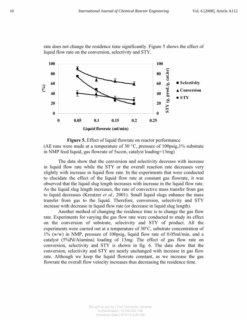
rate does not change the residence time significantly. Figure 5 shows the effect of liquid flow rate on the conversion, selectivity and STY.
Figure 5. Effect of liquid flowrate on reactor performance (All runs were made at a temperature of 30 °C, pressure of 100psig,1% substrate in NMP feed liquid, gas flowrate of 5sccm, catalyst loading=13mg)
The data show that the conversion and selectivity decrease with increase in liquid flow rate while the STY or the overall reaction rate decreases very slightly with increase in liquid flow rate. In the experiments that were conducted to elucidate the effect of the liquid flow rate at constant gas flowrate, it was observed that the liquid slug length increases with increase in the liquid flow rate. As the liquid slug length increases, the rate of convective mass transfer from gas to liquid decreases (Kreutzer et al., 2001). Small liquid slugs enhance the mass transfer from gas to the liquid. Therefore, conversion, selectivity and STY increase with decrease in liquid flow rate (or decrease in liquid slug length).
Another method of changing the residence time is to change the gas flow rate. Experiments for varying the gas flow rate were conducted to study its effect on the conversion of substrate, selectivity and STY of product. All the experiments were carried out at a temperature of 30°C, substrate concentration of 1% (w/w) in NMP, pressure of 100psig, liquid flow rate of 0.05ml/min, and a catalyst (5%Pd/Alumina) loading of 13mg. The effect of gas flow rate on conversion, selectivity and STY is shown in fig. 6. The data show that the conversion, selectivity and STY are nearly unchanged with increase in gas flow rate. Although we keep the liquid flowrate constant, as we increase the gas flowrate the overall flow velocity increases thus decreasing the residence time.
10 International Journal of Chemical Reactor Engineering Vol. 6 [2008], Article A112
Brought to you by | York University LibrariesAuthenticated | 10.248.254.158
Download Date | 8/12/14 8:26 AM

020406080
100120
0 2 4 6 8 10 12
Gas flowrate (sccm)
(%)
0
20
40
60
80
100
STY
(g. p
rod.
/g. c
at.h
r)
Selectivity
Conversion
STY
Figure 6. Effect of gas flowrate on reactor performance (All runs were made at a temperature of 30°C, pressure of 100psig,1% substrate in NMP feed liquid, liquid flowrate of 0.05ml/min, catalyst loading=13mg)
Theoretically, if the reaction is controlled by kinetics, the conversion, selectivity and STY should decrease with decrease in residence time; on the other hand, if the reaction is primarily controlled by mass transfer, the conversion, selectivity and STY should increase with increase in gas flowrate due to better mass transfer. However, if we assume a pseudo-homogeneous model for the flow, then the gas flowrate will not affect the conversion, selectivity and STY; on the other hand, if we assume a two phase flow model, then the overall (liquid + gas) flowrate affects the conversion, selectivity and STY. The present results tend to agree with the pseudo-homogeneous model because the conversion, selectivity and STY are unchanged with gas flowrate. However, it is not clear if the reaction is controlled both by mass transfer or intrinsic kinetics under these operating conditions. The reduction of reaction residence time and the increase of mass transfer rate with increase in gas flowrate have an opposing effect so that the reaction performance does not change much. This observation has been clarified in the studies that follow by isolating the effect of residence time and mass transfer.
The isolation of the effect of residence time on the conversion, selectivity and STY was achieved by varying the catalyst loading with all the other operating conditions remaining constant. All the experiments were carried out at a temperature of 30°C, substrate concentration of 1% (w/w) in NMP, pressure of 100psig, liquid flow rate of 0.05ml/min, and H2 flow rate of 5sccm. Figure 7 shows the results; as expected the conversion and selectivity increase with increase in catalyst loading. The value of STY decreases with increase in catalyst
11Tadepalli and Lawal: Hydrogenation of Aromatic Nitro Ketone in a Microreactor
Brought to you by | York University LibrariesAuthenticated | 10.248.254.158
Download Date | 8/12/14 8:26 AM

0
20
40
60
80
100
120
0 5 10 15 20
Catalyst loading (mg)
(%)
0
20
40
60
80
100
120
STY
(g. p
rod.
/g. c
at.h
r)
SelectivityConversionSTY
loading because the average reactant concentration decreases at higher conversion.
The effect of mass transfer on the STY was studied by changing the overall flow velocity at the same residence time within the range of flowrates considered. The residence time was kept constant by increasing the amount of catalyst in proportion to the increase of flow velocity. Figure 8 shows the effect of overall velocity on STY. The fact that the reaction rate increases with increase in flow velocity indicates that mass transfer plays an important role. Therefore we can conclude that the reaction in microreactor is controlled by both mass transfer and intrinsic kinetics under the operating conditions used for these experiments.
Figure 7. Effect of catalyst loading on reactor performance (All runs were made at a temperature of 30 °C, pressure of 100psig, 1% substrate in NMP feed liquid, gas and liquid flowrate of 5sccm and 0.05ml/min respectively)
12 International Journal of Chemical Reactor Engineering Vol. 6 [2008], Article A112
Brought to you by | York University LibrariesAuthenticated | 10.248.254.158
Download Date | 8/12/14 8:26 AM

0
20
40
60
80
100
120
0 2 4 6 8 10 12 14
Overall flow velocity (cm/s)
STY
(g p
rod/
g ca
t-hr
)
Figure 8. Effect of overall flow velocity at same residence time (All runs were made at a temperature of 30 °C, pressure of 100psig, 1% substrate in NMP feed liquid)
3.3.4. Effect of substrate concentration
To study the effect of substrate concentration on reactor performance, experiments were carried out in the concentration range of 1-10% (w/w) substrate in NMP, temperature of 50°C, 100psig reactor pressure, and a catalyst loading of 13mg of 5% Pd/Alumina. The liquid and hydrogen gas flow rates were 0.05ml/min and 5sccm respectively. Figure 9 shows that the increase in substrate concentration results in decrease in conversion. The selectivity is lower at higher substrate concentration indicating that the rate of intermediate formation may have a stronger dependency on the substrate concentration. The STY increases up to substrate concentration of 4% (w/w) in NMP and then starts to decrease thereafter. Similar trend was observed in our recent work on the study of hydrogenation of o-nitroanisole at different substrates concentrations (Tadepalli et al., 2007). We observed that the rate of amine formation at high concentrations of o-nitroanisole is low because of substrate inhibition effect present at high concentrations as a result of weak adsorption of hydrogen on catalyst surface in comparison to nitro compound.
13Tadepalli and Lawal: Hydrogenation of Aromatic Nitro Ketone in a Microreactor
Brought to you by | York University LibrariesAuthenticated | 10.248.254.158
Download Date | 8/12/14 8:26 AM

0
20
40
60
80
100
120
0 2 4 6 8 10 12
Reactant conc. (w/w)
(%)
0
20
40
60
80
100
120
140
STY
(g. p
rod.
/g. c
at.h
r)
SelectivityConversionSTY
Figure 9. Effect of substrate concentration on reactor performance (All the runs were made at 30°C, 100 psig reactor pressure, liquid flowrate of 0.05 ml/min, gas flowrate of 5sccm, catalyst loading= 13 mg)
3.4. Kinetic studies
Kinetic studies of fast hydrogenation reactions present a unique challenge because these reactions are usually limited by mass transfer steps. The surface reaction is so rapid that it is difficult to overcome the mass transfer resistances to obtain the true intrinsic kinetics of the reaction. The overall hydrogenation rate for such reactions may be influenced by transport effects such as gas-liquid, liquid-solid mass transfer and internal mass transfer. Hence, prior to determining the true intrinsic kinetics of the present reaction, appropriate conditions have to be selected where the transport effects can be considered to be negligible. The approach used for conducting kinetic studies for this reaction was similar to that used for the hydrogenation of o-nitroanisole in a microreactor (Tadepalli et al., 2007). The first step in this approach is to evaluate the possible mass and heat transfer limitations within the operating conditions used for the experiments, and then study the intrinsic kinetics of the reaction.
3.4.1. Analysis of internal mass transfer effect
The effect of internal mass transfer was studied experimentally by varying the catalyst particle sizes. Experiments were conducted using two different catalyst particle size ranges, 45-75 micron (average size = 60 micron) and 75-150 micron (average size = 112 micron) at different hydrogen pressure values to determine
14 International Journal of Chemical Reactor Engineering Vol. 6 [2008], Article A112
Brought to you by | York University LibrariesAuthenticated | 10.248.254.158
Download Date | 8/12/14 8:26 AM

the effect of catalyst particle size on the reaction rate (STY). The effect of particle size on STY at different pressures is shown in fig. 10. The data in this figure indicate that the values of STY at different pressure levels considered are nearly the same for the two particle sizes utilized. Hence, it can be concluded that the influence of internal diffusion on the reaction rate can be neglected for the range of pressures and particle sizes studied.
To further validate this conclusion, calculation of the catalyst effectiveness factor (ηeff) was performed. The effectiveness factor calculated under the reaction conditions used for the above experiments ranged from 0.88-0.95 as shown in Table 1. Since the effectiveness factor for these operating conditions is close to 1 (ηeff 1), the calculations confirm the experimental data which indicate that internal mass transfer does not affect the reaction rate significantly.
0
50
100
150
200
250
300
0 20 40 60 80 100 120
Partial Pressure of H2 (psig)
STY
(g p
rod/
g ca
t-hr)
75-150 microns45-75 microns
Figure 10. Effect of particle size on STY at different pressures (All runs were made at a temperature of 50 °C, 1% substrate in NMP feed liquid, liquid flow rate of 0.4 ml/min, Overall gas flow rate = 40 sccm, catalyst loading=13mg)
15Tadepalli and Lawal: Hydrogenation of Aromatic Nitro Ketone in a Microreactor
Brought to you by | York University LibrariesAuthenticated | 10.248.254.158
Download Date | 8/12/14 8:26 AM
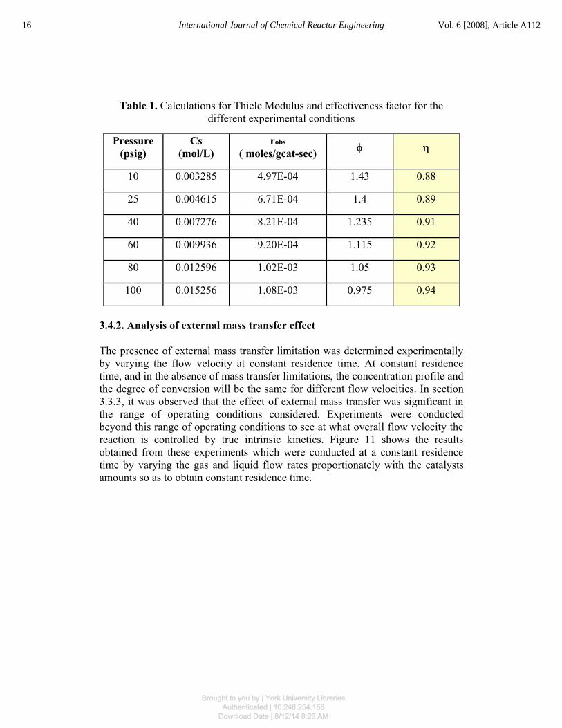
Table 1. Calculations for Thiele Modulus and effectiveness factor for the different experimental conditions
Pressure (psig)
Cs (mol/L)
robs ( moles/gcat-sec)
φ η
10 0.003285 4.97E-04 1.43 0.88
25 0.004615 6.71E-04 1.4 0.89
40 0.007276 8.21E-04 1.235 0.91
60 0.009936 9.20E-04 1.115 0.92
80 0.012596 1.02E-03 1.05 0.93
100 0.015256 1.08E-03 0.975 0.94
3.4.2. Analysis of external mass transfer effect
The presence of external mass transfer limitation was determined experimentally by varying the flow velocity at constant residence time. At constant residence time, and in the absence of mass transfer limitations, the concentration profile and the degree of conversion will be the same for different flow velocities. In section 3.3.3, it was observed that the effect of external mass transfer was significant in the range of operating conditions considered. Experiments were conducted beyond this range of operating conditions to see at what overall flow velocity the reaction is controlled by true intrinsic kinetics. Figure 11 shows the results obtained from these experiments which were conducted at a constant residence time by varying the gas and liquid flow rates proportionately with the catalysts amounts so as to obtain constant residence time.
16 International Journal of Chemical Reactor Engineering Vol. 6 [2008], Article A112
Brought to you by | York University LibrariesAuthenticated | 10.248.254.158
Download Date | 8/12/14 8:26 AM
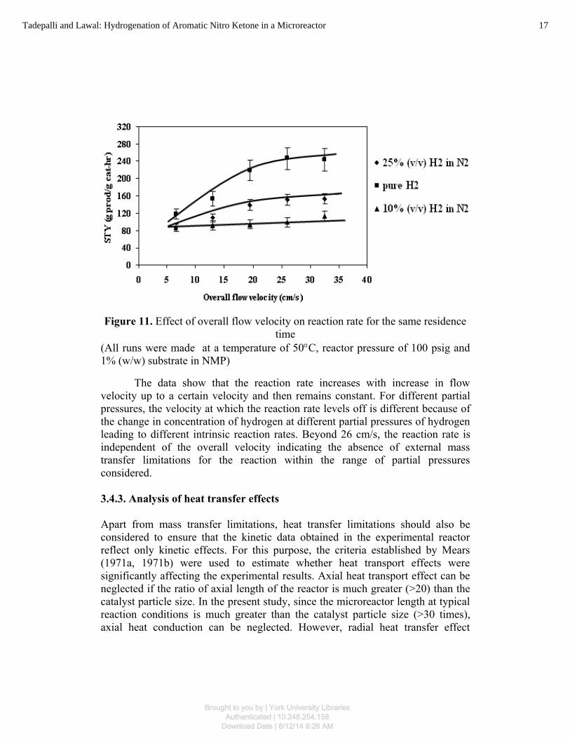
Figure 11. Effect of overall flow velocity on reaction rate for the same residence time
(All runs were made at a temperature of 50°C, reactor pressure of 100 psig and 1% (w/w) substrate in NMP)
The data show that the reaction rate increases with increase in flow velocity up to a certain velocity and then remains constant. For different partial pressures, the velocity at which the reaction rate levels off is different because of the change in concentration of hydrogen at different partial pressures of hydrogen leading to different intrinsic reaction rates. Beyond 26 cm/s, the reaction rate is independent of the overall velocity indicating the absence of external mass transfer limitations for the reaction within the range of partial pressures considered.
3.4.3. Analysis of heat transfer effects
Apart from mass transfer limitations, heat transfer limitations should also be considered to ensure that the kinetic data obtained in the experimental reactor reflect only kinetic effects. For this purpose, the criteria established by Mears (1971a, 1971b) were used to estimate whether heat transport effects were significantly affecting the experimental results. Axial heat transport effect can be neglected if the ratio of axial length of the reactor is much greater (>20) than the catalyst particle size. In the present study, since the microreactor length at typical reaction conditions is much greater than the catalyst particle size (>30 times), axial heat conduction can be neglected. However, radial heat transfer effect
17Tadepalli and Lawal: Hydrogenation of Aromatic Nitro Ketone in a Microreactor
Brought to you by | York University LibrariesAuthenticated | 10.248.254.158
Download Date | 8/12/14 8:26 AM

cannot be assumed to be negligible because radial temperature gradients can lead to reaction rates several thousand folds greater at the axis of the reactor than at the wall due to the absence of heat removal pathway from the axis of the reactor to the environment. A criterion for quantitative analysis of radial heat transport limitations is given by the Damkőhler number for heat transfer (Mears 1971a) (Da) which is defined by the following equation:
D H r RT b
RTE
aobs o
w
w
a=
− − −+
<Δ ( )( )
( ).1
10 4
2ελ (1)
If the left hand side of the above equation is smaller than the right hand side, the transverse temperature difference in the reactor would be less than 5%. In this case, the left hand side was found to be one order of magnitude smaller than the right hand side. Hence, it can be concluded that the heat transfer effects can be neglected in the micro reactor. With all the above considerations, appropriate reaction conditions have been obtained in the microreactor where the reaction is controlled by surface kinetics and not significantly influenced by mass and heat transfer resistances.
3.4.4. Rate analysis using differential method
Experiments were conducted in the microreactor under different operating conditions to determine the kinetic rate expression for this reaction. For these experiments, the overall flow velocity was maintained above 26 cm/s to ensure the absence of external mass transfer limitations and, the conversion of the reactants was limited to 10% so that a differential reactor can be assumed to find the dependence of the reaction rates on the reactant concentrations. The high overall flow velocities used for these experiments resulted in a pressure drop between 10-25psig across the reactor. Hence, the concentration of hydrogen was calculated based on the average partial pressure of hydrogen across the reactor.
The effect of hydrogen pressure on the rate of disappearance of nitro compound was investigated in a range of 0-100psig, at temperatures of 30, 40 and 50oC and substrate concentration of 1% (w/w) in NMP. The results are presented in fig. 12. The rate of disappearance of nitro compound first increases with increase in hydrogen pressure and then remains constant at higher hydrogen pressures.
18 International Journal of Chemical Reactor Engineering Vol. 6 [2008], Article A112
Brought to you by | York University LibrariesAuthenticated | 10.248.254.158
Download Date | 8/12/14 8:26 AM

0
1
2
3
4
5
6
0 20 40 60 80 100 120
Partial Pressure of H2 (psig)
Rat
e (m
ol/g
cat
-hr)
30 deg.C 40 deg.C 50 deg.C
Figure 12. Effect of H2 partial pressure on the reaction rate of disappearance of nitro compound
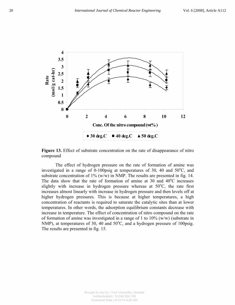
The effect of concentration of nitro compound on the rate of disappearance of nitro compound was investigated in the concentration range of 1 to 10% (w/w) at temperatures of 30, 40 and 50oC, and a hydrogen pressure of 100psig. The results are presented in fig. 13. The data show that the reaction rate first increases and then decreases with nitro compound concentration. The decrease in the reaction rate at high nitro compound concentration may be because of substrate inhibition effect present at such high concentrations as mentioned in section 3.3.4. This suggests that Langmuir Hinshelwood expression should be considered for the rate equation.
19Tadepalli and Lawal: Hydrogenation of Aromatic Nitro Ketone in a Microreactor
Brought to you by | York University LibrariesAuthenticated | 10.248.254.158
Download Date | 8/12/14 8:26 AM
00.5
11.5
22.5
33.5
4
0 2 4 6 8 10 12
Conc. Of the nitro compound (wt%)
Rat
e (m
ol/g
cat
-hr)
30 deg.C 40 deg.C 50 deg.C
Figure 13. Effect of substrate concentration on the rate of disappearance of nitro compound
The effect of hydrogen pressure on the rate of formation of amine was investigated in a range of 0-100psig at temperatures of 30, 40 and 50oC, and substrate concentration of 1% (w/w) in NMP. The results are presented in fig. 14. The data show that the rate of formation of amine at 30 and 40oC increases slightly with increase in hydrogen pressure whereas at 50oC, the rate first increases almost linearly with increase in hydrogen pressure and then levels off at higher hydrogen pressures. This is because at higher temperatures, a high concentration of reactants is required to saturate the catalytic sites than at lower temperatures. In other words, the adsorption equilibrium constants decrease with increase in temperature. The effect of concentration of nitro compound on the rate of formation of amine was investigated in a range of 1 to 10% (w/w) (substrate in NMP), at temperatures of 30, 40 and 50oC, and a hydrogen pressure of 100psig. The results are presented in fig. 15.
20 International Journal of Chemical Reactor Engineering Vol. 6 [2008], Article A112
Brought to you by | York University LibrariesAuthenticated | 10.248.254.158
Download Date | 8/12/14 8:26 AM

00.20.40.60.8
11.21.41.61.8
0 20 40 60 80 100 120
Partial Pressure of H2 (psig)
Rat
e (m
ol/g
cat
-hr)
30 deg.C 40 deg.C 50 deg.C
Figure 14. Effect of H2 partial pressure on the reaction rate of formation of amine
Figure 15. Effect of substrate concentration on the rate of formation of amine
0
0.2
0.4
0.6
0.8
1
0 2 4 6 8 10 12Conc. Of the nitro compound (wt%)
Rat
e(m
ol/g
cat
-hr)
30 deg.C 40 deg.C 50 deg.C
21Tadepalli and Lawal: Hydrogenation of Aromatic Nitro Ketone in a Microreactor
Brought to you by | York University LibrariesAuthenticated | 10.248.254.158
Download Date | 8/12/14 8:26 AM

The rate first increases with increase in nitro compound concentration and then decreases slightly with further increase in concentration of nitro compound. A comparison of the data of figures 13 and 15 shows that the rate of disappearance of nitro compound is higher than the rate of formation of amine, at similar conditions. This suggests that the hydrogenation of the nitro compound to intermediate is faster than the hydrogenation of intermediate to product. For the purpose of kinetic study, the overall reaction was split into two-step series reaction as shown in fig. 16.
Figure 16. Reaction pathway for the hydrogenation of nitro compound
3.4.5. Kinetic modeling
Langmuir-Hinshelwood (L-H) model was used to develop rate equations for both the reactions. The L-H model for catalytic reactions typically involves a sequence of three steps:
1. Adsorption of the reactants 2. Surface reaction 3. Desorption of the products.
For each of the individual reactions shown in fig. 16, these steps occur on palladium sites represented by ‘(s)’. The mechanistic schemes for both reactions are shown in figures 17 and 18 respectively. Although the mechanisms shown in figures 17 and 18 correspond to competitive reaction (where the two reactants compete with each other for the same site) and non-dissociative adsorption of hydrogen, other mechanisms such as non-competitive reaction/non-dissociative adsorption of hydrogen, competitive reaction/ dissociative adsorption of hydrogen, and competitive reaction/ dissociative adsorption of hydrogen are also considered. Based on these mechanisms, different rate equations are derived
R
NO2
R+ 2H2
NHOH
+ H2O
+ H2O
NH2
+ H2
R
NHOH
R
I
II
22 International Journal of Chemical Reactor Engineering Vol. 6 [2008], Article A112
Brought to you by | York University LibrariesAuthenticated | 10.248.254.158
Download Date | 8/12/14 8:26 AM

considering each step as the rate limiting step for both reactions. The rate equations are derived by neglecting the concentrations and surface coverage of intermediates and products on the catalytic sites at low conversions of the reactants. These rate equations are listed in Table 2.
Reaction I- Competitive Adsorption
Figure 17. Mechanistic scheme for Reaction I
23Tadepalli and Lawal: Hydrogenation of Aromatic Nitro Ketone in a Microreactor
Brought to you by | York University LibrariesAuthenticated | 10.248.254.158
Download Date | 8/12/14 8:26 AM

Reaction II- Competitive Adsorption
Figure 18. Mechanistic scheme for Reaction II
N+
H2 + (s) H2(s)
+ H2(s)N(s)
Adsorption of Reactants
N
(s)N
H
H
Desorption of the product
+ (s)N
H
H(s)N
H
H
Surface Reaction
+ H2O + (s)
H
OH (s)(s)
H
OH
H
OH
R R
RR
R R
24 International Journal of Chemical Reactor Engineering Vol. 6 [2008], Article A112
Brought to you by | York University LibrariesAuthenticated | 10.248.254.158
Download Date | 8/12/14 8:26 AM
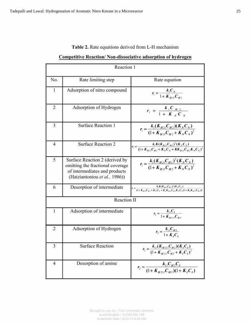
Table 2. Rate equations derived from L-H mechanism
Competitive Reaction/ Non-dissociative adsorption of hydrogen
Reaction 1
No. Rate limiting step Rate equation
1 Adsorption of nitro compound 221
11 1 HH
N
CKCkr
+=
2 Adsorption of Hydrogen NN
H
CKCkr
+=
121
1
3 Surface Reaction 1 2
221
22111 1 )(
))((
NNHH
NNHH
CKCKCKCKkr
++=
4 Surface Reaction 2 2
221221
22211
1 1 )()()(
NNHHNNHH
NNHH
CKCKKCKCKCKCKKkr
+++=
5 Surface Reaction 2 (derived by omitting the fractional coverage of intermediates and products (Hatziantoniou et al., 1986))
3221
22211
1 1 )()()(
NNHH
NNHH
CKCKCKCKkr
++=
6 Desorption of intermediate ))((
)()(
221221221
22211
1 11 HHbNNHHaNNHH
NNHH
CKKCKCKKCKCKCKCKKkr
++++=
Reaction II
1 Adsorption of intermediate 2211
112 1 HH
I
CKCkr
+=
2 Adsorption of Hydrogen II
H
CKCkr
+=
1211
2
3 Surface Reaction 2
2211
2211112 1 )(
))((
IIHH
IIHH
CKCKCKCKkr
++=
4 Desorption of amine ))(( IIHH
IH
CKCKCCkr
++=
11 2211
2112
25Tadepalli and Lawal: Hydrogenation of Aromatic Nitro Ketone in a Microreactor
Brought to you by | York University LibrariesAuthenticated | 10.248.254.158
Download Date | 8/12/14 8:26 AM
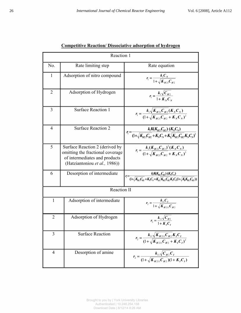
Competitive Reaction/ Dissociative adsorption of hydrogen
Reaction 1
No. Rate limiting step Rate equation
1 Adsorption of nitro compound 221
11 1 HH
N
CKCkr
+=
2 Adsorption of Hydrogen NN
H
CKCk
r+
=1
211
3 Surface Reaction 1 2
221
22111 1 )(
)(
NNHH
NNHH
CKCKCKCKk
r++
=
4 Surface Reaction 2 2
221221
22111 1 )(
)()(
NNHHNNHH
NNHH
CKCKKCKCKCKCKKkr
+++=
5 Surface Reaction 2 (derived by omitting the fractional coverage of intermediates and products
(Hatziantoniou et al., 1986))
3221
22211
1 1 )()()(
NNHH
NNHH
CKCKCKCKkr
++=
6 Desorption of intermediate ))((
)()(
221221221
22111 11 HHbNNHHaNNHH
NNHH
CKKCKCKKCKCKCKCKKkr
++++=
Reaction II
1 Adsorption of intermediate 2211
112 1 HH
I
CKCkr
+=
2 Adsorption of Hydrogen II
H
CKCk
r+
=1
2112
3 Surface Reaction 2
2211
2211112 1 )( IIHH
IIHH
CKCKCKCKk
r++
=
4 Desorption of amine ))(( IIHH
IH
CKCKCCk
r++
=11 2211
2112
26 International Journal of Chemical Reactor Engineering Vol. 6 [2008], Article A112
Brought to you by | York University LibrariesAuthenticated | 10.248.254.158
Download Date | 8/12/14 8:26 AM

Non-Competitive Reaction/ Non-dissociative adsorption of hydrogen
Reaction 1
No. Rate limiting step Rate equation
1 Adsorption of nitro compound
NCkr 11 =
2 Adsorption of Hydrogen
211 HCkr =
3 Surface Reaction 1 ))((
))((
NNHH
NNHH
CKCKCKCKkr
++=
11 221
22111
4 Surface Reaction 2 ))((
)()(
221221
22211
1 11 HHNNaNNHH
NNHH
CKCKKCKCKCKCKKkr
+++=
5 Desorption of intermediate ))((
)()(
221221
22211
1 11 HHbHHNNaNN
NNHH
CKKCKCKKCKCKCKKkr++
=+
Reaction II
1 Adsorption of intermediate
ICkr 112 =
2 Adsorption of Hydrogen
2112 HCkr =
3 Surface Reaction ))((
))((
IIHH
IIHH
CKCKCKCKkr
++=
11 2211
2211112
4 Desorption of amine )(
)()(
2211
2211112 1 HHIIaII
IIHH
CKCKKCKCKCKKkr
++=
27Tadepalli and Lawal: Hydrogenation of Aromatic Nitro Ketone in a Microreactor
Brought to you by | York University LibrariesAuthenticated | 10.248.254.158
Download Date | 8/12/14 8:26 AM

Non-Competitive Reaction/ Dissociative adsorption of hydrogen
Reaction 1
No. Rate limiting step Rate equation
1 Adsorption of nitro compound
NCkr 11 =
2 Adsorption of Hydrogen 211 HCkr =
3 Surface Reaction 1
))(()(
NNHH
NNHH
CKCKCKCKk
r++
=11 221
22111
4 Surface Reaction 2 ))((
)()(
221221
22111 11 HHNNaNNHH
NNHH
CKCKKCKCKCKCKKkr
+++=
5 Desorption of intermediate ))((
)()(
221221
22111 11 HHbHHNNaNN
NNHH
CKKCKCKKCKCKCKKkr++
=+
Reaction II
1 Adsorption of intermediate ICkr 112 =
2 Adsorption of Hydrogen 2112 HCkr =
3 Surface Reaction
))(( IIHH
IIHH
CKCKCKCKk
r++
=11 2211
2211112
4 Desorption of amine
)( 2211
2211112 1 HHIIaII
IIHH
CKCKKCKCKCKKk
r++
=
The experimental rate data obtained were fitted to these rate equations and were subjected to non-linear regression analysis to estimate the kinetic constants. Based on the best fit in the regression analysis, it was found that surface reactions
28 International Journal of Chemical Reactor Engineering Vol. 6 [2008], Article A112
Brought to you by | York University LibrariesAuthenticated | 10.248.254.158
Download Date | 8/12/14 8:26 AM

assuming competitive adsorption and non-dissociative adsorption of hydrogen were the rate controlling steps for the two reactions.
For reaction I (surface reaction 2 controlling)
3221
22211
1 1 )()()(
HHNN
NNHH
CKCKCKCKkr
++= (2)
For reaction II (surface reaction controlling)
22211
2211112 1 )(
))((
IIHH
IIHH
CKCKCKCKkr
++= (3)
The concentration of hydrogen in the reaction medium was obtained from the solubility data for H2 in NMP from the work of Brunner (1985). The values of the kinetic constants obtained using the optimization program for these models are given in Table 3. Table 3 shows that the equilibrium constants of hydrogen for the two reactions are different. This may be due to the influence of other reactants competing for the same palladium sites as hydrogen.
Table 3. Kinetic constants and regression coefficients for the reactions
Reaction I
Temperature (deg.C) kI (mol/g-hr) KN (L/mol) KH2I (L/mol) R2
30 69.57±0.03 3.07±0.002 174.64±0.096 0.99
40 134.31± 21.89 2.73±0.36 122.59±16.71 0.97
50 296.11± 0.10 2.36±0.001 71.7±0.02 0.98
Reaction II
Temperature (deg.C) kII (mol/g-hr) KI (L/mol) KH2II (L/mol) R2
30 1.62± 0.002 203.23±0.91 303.99±1.67 0.97
40 3.96±0.003 152.49±0.66 126.09± 0.24 0.99
50 13.85±0.06 90.53± 2.46 51.15± 0.36 0.98
29Tadepalli and Lawal: Hydrogenation of Aromatic Nitro Ketone in a Microreactor
Brought to you by | York University LibrariesAuthenticated | 10.248.254.158
Download Date | 8/12/14 8:26 AM

The rates predicted from the rate equations agree with the experimental rates within 10% error. The activation energies and heat of adsorption of the reactants for reactions I and II were determined from the kinetic constants using the Arrhenius equations:
For rate constant
k k eo
EaRT=
−
(4)
For equilibrium constants
K K eo
HRT=
− Δ
(5)
where k is the rate constant for the reaction, k0 is the pre-exponential factor for the reaction, Ea is the activation energy for the reaction, K is the equilibrium constant for adsorption of the reactant in the presence of other reactant, K0 is the pre-exponential factor for the adsorption of the reactant in the presence of other reactant, ΔH is the heat of adsorption for the reactant in the presence of other reactant and T is the temperature in Kelvin. The pre-exponential factors, activation energies and heat of adsorption of reactants calculated using the Arrhenius equations for various kinetics constants are given in Table 4. Table 4 shows that the heats of adsorption of hydrogen for the two reactions are different. This difference may also be due to the presence of other competitive reactants that are competing for the same sites.
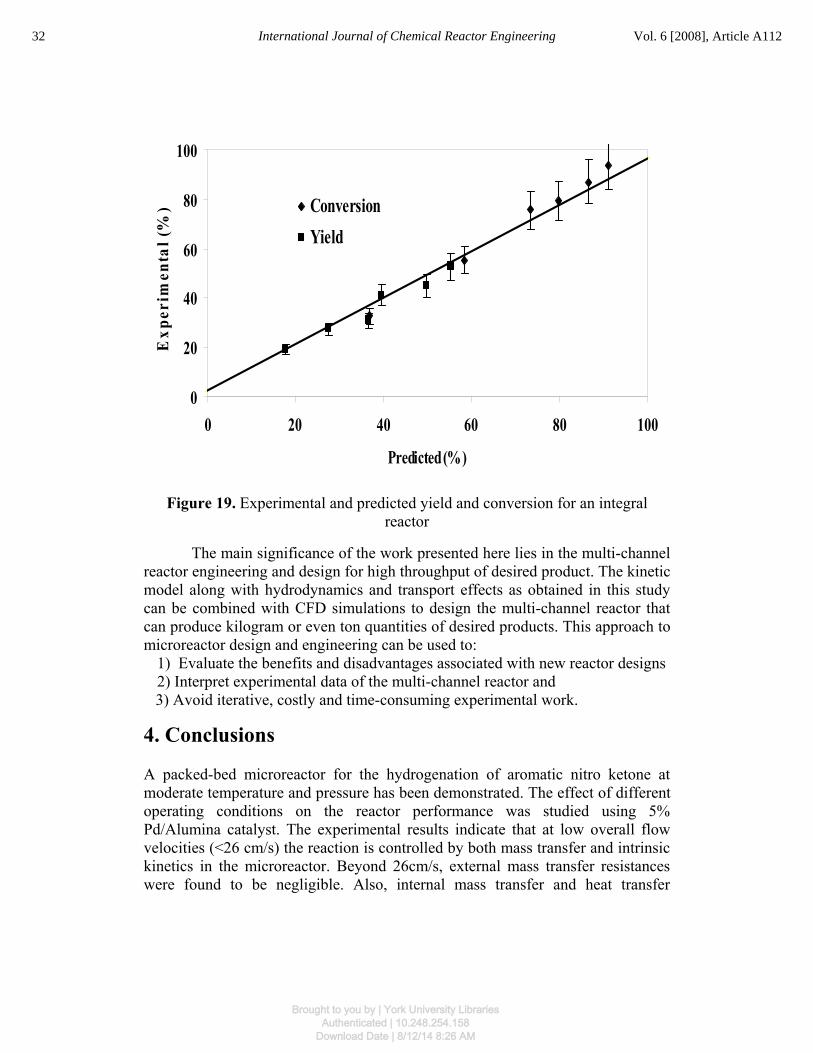
In order to further establish the validity of the above rate equations and associated kinetic parameters of the overall reaction, a comparison was made between the experimental data obtained under integral conditions and the theoretical predictions from the above rate equations. Experiments were carried out at different hydrogen pressures and higher amount of catalyst loading under kinetically controlled conditions. The model predictions and experimental data for the yield of the product and the conversion of the reactant under these reaction conditions are shown in fig. 19, and are within 5-10% of each other. This excellent agreement suggests that the rate parameters determined here represent the reactor performance data obtained under both differential and integral conditions.
30 International Journal of Chemical Reactor Engineering Vol. 6 [2008], Article A112
Brought to you by | York University LibrariesAuthenticated | 10.248.254.158
Download Date | 8/12/14 8:26 AM

Table 4. Pre-exponential factors, activation energies for the reactions and heats of adsorption of the reactants
Pre-exponential factor
Reaction I
Intrinsic Constants Values R2
kI0 (mol/g-hr) 9.46E+11 0.9948
KN0 (L/mol) 0.045863 0.994
KH2I0 (L/mol) 0.000107 0.9815
Reaction II
kII0 (mol/g-hr) 1.57E+15 0.987
KI0 (L/mol) 0.000472 0.9665
KH2II0 (L/mol) 9.86E-11 0.9993
Activation energy and heats of adsorption
Reaction I
Intrinsic Constants Values R2
Ea (kJ/mol) 58.85 0.9948
ΔHN(kJ/mol) -10.6 0.994
ΔHH2I(kJ/mol) -36.13 0.9815
Reaction II
Ea (kJ/mol) 87.11 0.987
ΔHI(kJ/mol) -32.78 0.9665
ΔHH2II(kJ/mol) -72.47 0.9993
31Tadepalli and Lawal: Hydrogenation of Aromatic Nitro Ketone in a Microreactor
Brought to you by | York University LibrariesAuthenticated | 10.248.254.158
Download Date | 8/12/14 8:26 AM
0
20
40
60
80
100
0 20 40 60 80 100
Predicted (%)
Exp
erim
enta
l (%
)
ConversionYield
Figure 19. Experimental and predicted yield and conversion for an integral reactor
The main significance of the work presented here lies in the multi-channel reactor engineering and design for high throughput of desired product. The kinetic model along with hydrodynamics and transport effects as obtained in this study can be combined with CFD simulations to design the multi-channel reactor that can produce kilogram or even ton quantities of desired products. This approach to microreactor design and engineering can be used to:
1) Evaluate the benefits and disadvantages associated with new reactor designs 2) Interpret experimental data of the multi-channel reactor and
3) Avoid iterative, costly and time-consuming experimental work.
4. Conclusions
A packed-bed microreactor for the hydrogenation of aromatic nitro ketone at moderate temperature and pressure has been demonstrated. The effect of different operating conditions on the reactor performance was studied using 5% Pd/Alumina catalyst. The experimental results indicate that at low overall flow velocities (<26 cm/s) the reaction is controlled by both mass transfer and intrinsic kinetics in the microreactor. Beyond 26cm/s, external mass transfer resistances were found to be negligible. Also, internal mass transfer and heat transfer
32 International Journal of Chemical Reactor Engineering Vol. 6 [2008], Article A112
Brought to you by | York University LibrariesAuthenticated | 10.248.254.158
Download Date | 8/12/14 8:26 AM
resistances were established to be negligible in the microreactor. Hence, the reaction is kinetically controlled in the microreactor under these reaction conditions.
Two separate reaction steps were identified from the kinetic studies: The reduction of nitro compound to hydroxyl amine and the further reduction of hydroxyl amine to amine. Langmuir-Hinshelwood type rate expressions were found to be suitable for these reaction steps with surface reactions controlling the two reaction steps. A set of rate equations was derived based on L-H model and the kinetic rate constants were obtained from regression of the experimental data in a differential microreactor. The obtained kinetics were able to predict the integral reactor behavior under kinetic-controlled regime. In spite of the excellent mass transfer characteristics of the microreactor, there are limited studies on the use of microreactor for obtaining intrinsic kinetics of fast reactions. The present study has demonstrated the use of a packed-bed microreactor for obtaining the intrinsic kinetics of a fast hydrogenation reaction that is controlled by mass transfer in conventional reactors.
Notation
b ratio of diluent to catalyst volume, dimensionless
CH2 concentration of hydrogen in the liquid mixture, mol/L
CN concentration of nitro compound in the liquid mixture, mol/L
CI concentration of intermediate in the liquid mixture, mol/L
dp diameter of the catalyst particle, μm
Da Damkőhler number for heat transfer, dimensionless
De effective diffusion coefficient of hydrogen in the particle, cm2/s
Dm hydrogen diffusion coefficient in the liquid reactant, cm2/sec
Ea activation energy, kJ/mol
H heat transfer coefficient for the reactants,W/m2-K
K0 pre-exponential factor for reaction , mol/g-hr
33Tadepalli and Lawal: Hydrogenation of Aromatic Nitro Ketone in a Microreactor
Brought to you by | York University LibrariesAuthenticated | 10.248.254.158
Download Date | 8/12/14 8:26 AM

kI intrinsic kinetic rate constant for reaction I, mol/g-hr
kII intrinsic kinetic rate constant for reaction II, mol/g-hr
kI0 pre-exponential factor for the reaction I , mol/g-hr
kII0 pre-exponential factor for the reaction II , mol/g-hr
K Equilibrium constant, L/mol
Ka Equilibrium constant, L/mol
Kb Equilibrium constant, L/mol
K0 pre-exponential factor for reactant in the presence of other reactant, L/mol
KH2I0 pre-exponential factor for hydrogen in the presence of nitro compound for reaction I, L/mol
KH2I equilibrium constant for hydrogen in the presence of nitro compound for reaction I, L/mol
KH2II0 pre-exponential factor for hydrogen in the presence of nitro compound for reaction II, L/mol
KH2II equilibrium constant for hydrogen in the presence of nitro compound for reaction II, L/mol
KI equilibrium constant for intermediate in the presence of hydrogen, L/mol
KI0 pre-exponential factor for intermediate in the presence of hydrogen, L/mol
KN equilibrium constant for nitro compound in the presence of hydrogen, L/mol
KN0 pre-exponential factor for nitro compound in the presence of hydrogen, L/mol
rI reaction rate for reaction I, mol/g-hr R2 reaction rate for reaction II, mol/g-hr R universal gas constant, J/mol.K R2 regression coefficient, dimensionless Ro radius of the tubular reactor, m
34 International Journal of Chemical Reactor Engineering Vol. 6 [2008], Article A112
Brought to you by | York University LibrariesAuthenticated | 10.248.254.158
Download Date | 8/12/14 8:26 AM

Robs observed reaction rate, mol/m3s STY Space-Time Yield, g prod./(g cat. hr) T reaction temperature, K Tw reactor wall temperature, K Greek symbols
ρp density of catalyst particles, g/m3
Ε void fraction of catalyst bed, dimensionless ΔH enthalpy of reaction, kJ/mol ΔHN heat of adsorption of nitroanisole in the presence of hydrogen,
kJ/mol ΔHH2I heat of adsorption of hydrogen for reaction I in the presence
of nitro compound, kJ/mol ΔHH2II heat of adsorption of hydrogen for reaction II in the presence
of intermediate, kJ/mol ΔHI heat of adsorption of intermediate in the presence of
hydrogen, kJ/mol Λ effective thermal conductivity of porous catalyst, W/m-K φ Thiele Modulus, dimensionless ηeff catalyst effectiveness factor, dimensionless
References
Albers, P.; Pietsch, J.; Parker, S.F. Poisoning and deactivation of palladium catalysts. J. Mol. Cat A: Chem (2001) 173, 275.
Andersson, B.; Hatziantoniou, V.; Schöön, N. Mass transfer and selectivity in liquid-phase hydrogenation of nitro compounds in a monolithic catalyst reactor with segmented gas-liquid flow. Ind. Eng. Chem. Process Des. Dev. (1986) 25,964.
Bartholomew, C.H. Mechanisms of catalyst deactivation. Applied Cat. A: General(2001) 212, 17.
Broekhuis, R.R.; Machado, R.M.; Nordquist, A.F. The ejector driven monolith loop reactor—experiments and modelling. Catal. Today (2001) 69, 93.
35Tadepalli and Lawal: Hydrogenation of Aromatic Nitro Ketone in a Microreactor
Brought to you by | York University LibrariesAuthenticated | 10.248.254.158
Download Date | 8/12/14 8:26 AM

Brunner, E. Solubility of Hydrogen in 10 Organic Solvents at 298.15, 323.15, and 373.15 K, J. Chem. Eng. Data (1985) 30, 269.
Dummann, G.; Quittmann, U.; Gröschel, L.; Agar, D. W.; Wörz, O.; Morgenschweis, K. The capillary-microreactor: a new reactor concept for the intensification of heat and mass transfer in liquid–liquid reactions. Catal. Today (2003) 79-80, 433.
Fischer, R. H.; Weitz, H. M. Preparation and Reactions of Cyclic α-Nitroketones, Syntheses (1980) 261-282.
Födisch, R.; Kursawe, A.; HConicke, D. Immobilizing heterogeneous catalysts in microchannel reactors. Proceedings of the Sixth International Conference on Microreaction Technology, New Orleans, (2002) 140–146.
Hatziantoniou, V.; Andersson, B.; Schöön, N., Mass Transfer and Selectivlty in Liquid-Phase Hydrogenation of Nitro Compounds in a Monolithic Catalyst Reactor with Segmented Gas-Liquid Flow, Ind. Eng. Chem Process Des Dev., (1986) 25, 964.
Hessel, V.; Jähnisch, K.; Baerns, M.; Ehrfeld, W.; Haverkamp, V.; Löwe, H.; Wille, Ch.; Guber, A. E. Direct fluorination of toluene using elemental fluorine in gas/liquid microreactors. J. Fluorine Chem. (2000) 105, 117.
Hessel, V.; Yeong, K. K.; Gavriilidis, A.; Zapf, R. Catalyst preparation and deactivation issues for nitrobenzene hydrogenation in a microstructured falling film reactor. Catal. Today (2003) 81, 641.
Hessel, V.; Yeong, K. K.; Gavriilidis, A.; Zapf, R. Experimental studies of nitrobenzene hydrogenation in a microstructured falling film reactor. Chem.Eng.Sci. (2004) 59,3491.
Irandoust, S.; Andersson, B.; Bengtsson, E.; Silverstrom, M. Scale up of a monolytic catalyst reactor with two-phase flow. Ind. Eng. Chem. Res. (1989) 28,1489.
Kreutzer, M .T.; Du, P.; Heiszwolf, J. J.; Kapteijn, F.; Moulijn, J. A. Mass transfer characteristics of three-phase monolith reactors. Chem. Eng. Sci. (2001)56,6015.
Kreutzer, M. T.; Kapteijn, F.; Moulijn, J. A. Fast-gas-liquid-solid reactions in monoliths: A case study of nitro-aromatic hydrogenation. Catal. Today (2005) 105, 421.
36 International Journal of Chemical Reactor Engineering Vol. 6 [2008], Article A112
Brought to you by | York University LibrariesAuthenticated | 10.248.254.158
Download Date | 8/12/14 8:26 AM

Liu, W.; Roy, S.; Fu, X. Gas-Liquid Catalytic Hydrogenation Reaction in Small Catalyst Channel. AIChE J. (2005) 51, 2285.
Machado, R.M.; Parrillo, D.J.; Boehme, R.P.; Broekhuis, R.R. Use of a monolith catalyst for the hydrogenation of dinitrotoluene to toluenediamine. US Patent 6005143 (1999).
Mears, D. E. Diagnostic criteria for heat transport limitations in fixed bed reactors, J. Catal. (1971a) 20, 127.
Mears, D.E. Test for transport limitations in experimental catalytic reactors, Ind. Eng. Chem. Process Des. Dev. (1971b) 10, 541.
Nijhuis, T.A.; Dautzenberg, F.M.; Moulijn, J.A. Modelling of monolithic and trickle–bed reactors for the hydrogenation of styrene. Chem. Eng, Sci. (2003) 58,1113.
Nishimura, S. Handbook of heterogeneous catalytic hydrogenation for organic synthesis; John Wiley & Sons, Inc.; Canada, (2001) Chapter 9.
Tadepalli, S.; Halder, R.; Lawal, A. Catalytic Hydrogenation of o-nitroanisole in a Microreactor: Reactor Performance and Kinetic Studies. Chem.Eng.Sci. (2007a)62,2663.
Tadepalli, S.; Qian, D.; Lawal, A. Comparison of performances of microreactor and semi-batch reactor for catalytic hydrogenation of o-nitroanisole. Catal. Today(2007b) 125, 64.
Wada, Y.; Schmidt, M. A.; Jensen, K. F., Flow distribution and ozonolysis in gas-liquid multichannel reactors, Ind. Eng. Chem. Res., (2006) 45, 8036.
Zhao, F; Shirai, M.; Arai, M., Palladium-catalyzed homogeneous and heterogeneous Heck reactions in NMP and water-mixed solvents using organic, inorganic and mixed bases, J Mol. Cat. A: Chem., (2000) 154, 39.
Zhao, F.; Shirai, M.; Ikushima, Y.; Arai, M., The leaching and re-deposition of metal species from and onto conventional supported palladium catalysts in the Heck reaction of iodobenzene and methyl acrylate in N-methylpyrrolidone, J Mol. Cat. A: Chem., (2002) 180, 211.
37Tadepalli and Lawal: Hydrogenation of Aromatic Nitro Ketone in a Microreactor
Brought to you by | York University LibrariesAuthenticated | 10.248.254.158
Download Date | 8/12/14 8:26 AM