The calculation of venting areas for pressure relief of ... THE CALCULATION OF VENTING AREAS FOR...
9
46 THE CALCULATION OF VENTING AREAS FOR PRESSURE RELIEF OF EXPLOSIONS IN VESSELS By G. MUNDAY, Ph.D., D.I.C., B.Sc* SYNOPSIS In this paper an analysis of the pressure changes accompanying the venting of an explosion in a confined space is used to determine the discharge area required to protect process vessels. It will be shown, using an extension of the method suggested by Lewis and von Elbe 1 for closed vessels, that the pressure in the vessel is a function of the shape of fhevessel, the area and position of the vent, and the properties of the reacting species. Using these results equations have been developed to determine the minimum discharge area required for constant pressure venting above the critical pressure for sonic discharge. The theoretical equations have been tested by the application of published experimental data and in most cases there is close agreement between theory and practice. Introduction Considerable experimental information is available on the pressure developed in explosions in vessels, and the effects of venting. So far no rational analysis has been produced which satisfactorily accounts for discrepancies between results. Originally, investigations into explosions were performed in closed vessels and the provision of venting based on the ratio of valve area to vessel volume as deter- mined from the hydrodynamic theory of the discharge of gases from high pressure reservoirs. Later 2 it was found that the experimental work on closed vessels could not be applied in real cases on the basis of this simple model and correlations were made using the K factor representing the ratio of the vent area to the flame area. Explosion pressures have been calculated from basic considerations of flame propagation but so far only those dealing with closed spherical vessels have yielded satisfactory results. The analysis of what happens when an open vent is introduced in the vessel is complicated by the turbulence and mixing set up by the discharge. The formation of rare- faction waves which interact with the flame has been con- sidered as the basis of an analysis 3 but so far a solution has not been obtained. However, Rasbash and Rogowski 4 have suggested the possibility of a semi-empirical relation between the increased combustion rate, because of venting, and the Reynolds number of the flow in front of the flame. This appears to be first step towards a rational approach to the problem and it has suggested the following possible line of attack. General Theory Equations of conservation of mass and energy of burnt and unburnt elements of gas in a closed vessel are set up in the normal manner. Terms are included to account for the mass and energy of the gas which are lost from the system when the vent opens. An assumption of a power law for the variation of flame velocity with pressure is introduced, and a solution obtained for the state of the system at any instant of time. The turbulence generated by the venting process is assumed to increase the normal combustion rate by a factor which depends upon the relevant Reynolds number. * Department of Chemical Engineering and Chemical Tech- nology, Imperial College, Prince Consort Road, London. It is assumed that a flame moves through the gas and raises its temperature during the process of combustion. Heat is not transmitted in significant quantities through the gas but the increase in temperature and change of volume of the burnt gas cause a rise in pressure accompanied by adia- batic heating of the gas throughout the vessel. Thus every element of gas has its temperature raised in three operations; initially in its unburnt condition by adiabatic compression due to burning of elements of gas near the ignition centre; then in combustion; and finally in its burnt condition by adiabatic compression because of the burning of elements of gas further away from the ignition centre. Consider a gas element of mass and volume in a vessel of volume Initially the element is at an absolute pressure. and an absolute temperature and has a density and molecular weight and , The gas in the vessel ignites at a point some distance from the element and a flame spreads through the gas at a velocity which depends on the pressure and temperature. The heat evolved in this process induces a change in pressure which causes the temperature of all elements of unburnt gas to rise to according to the equations : Here the subscript refers to conditions in the unburnt gas at a time after ignition. is the volume occupied by one molecule of the gas and is a constant for all the elements of unburnt gas. When the flame reaches the element, it burns at constant pressure, and its temperature rises instantaneously to Since it has undergone a chemical change, the molecular weight changes to that of the products, The burnt element is compressed adiabatically from the temperature to the temperature as given implicitly by: and the equation of state. The subscription b refers to conditions just after burning and the subscript to con- ditions in the burnt element at a pressure Since each element enters the combustion zone at a different temperature the " initial" conditions in the burned state, as represented by : will vary from element to element. Hence, the term will only be a constant for each element and will depend SECOND SYMPOSIUM ON CHEMICAL PROCESS HAZARDS (1963: INSTN CHEM. ENGRS)
Transcript of The calculation of venting areas for pressure relief of ... THE CALCULATION OF VENTING AREAS FOR...
46
THE CALCULATION OF VENTING AREAS FOR PRESSURE RELIEF OF EXPLOSIONS IN VESSELS
By G. MUNDAY, Ph.D., D.I.C., B.Sc*
SYNOPSIS
In this paper an analysis of the pressure changes accompanying the venting of an explosion in a confined space is used to determine the discharge area required to protect process vessels. It will be shown, using an extension of the method suggested by Lewis and von Elbe1 for closed vessels, that the pressure in the vessel is a function of the shape of fhevessel, the area and position of the vent, and the properties of the reacting species. Using these results equations have been developed to determine the minimum discharge area required for constant pressure venting above the critical pressure for sonic discharge. The theoretical equations have been tested by the application of published experimental data and in most cases there is close agreement between theory and practice.
Introduction
Considerable experimental information is available on the pressure developed in explosions in vessels, and the effects of venting. So far no rational analysis has been produced which satisfactorily accounts for discrepancies between results. Originally, investigations into explosions were performed in closed vessels and the provision of venting based on the ratio of valve area to vessel volume as determined from the hydrodynamic theory of the discharge of gases from high pressure reservoirs. Later2 it was found that the experimental work on closed vessels could not be applied in real cases on the basis of this simple model and correlations were made using the K factor representing the ratio of the vent area to the flame area.
Explosion pressures have been calculated from basic considerations of flame propagation but so far only those dealing with closed spherical vessels have yielded satisfactory results. The analysis of what happens when an open vent is introduced in the vessel is complicated by the turbulence and mixing set up by the discharge. The formation of rarefaction waves which interact with the flame has been considered as the basis of an analysis3 but so far a solution has not been obtained. However, Rasbash and Rogowski4 have suggested the possibility of a semi-empirical relation between the increased combustion rate, because of venting, and the Reynolds number of the flow in front of the flame. This appears to be first step towards a rational approach to the problem and it has suggested the following possible line of attack.
General Theory
Equations of conservation of mass and energy of burnt and unburnt elements of gas in a closed vessel are set up in the normal manner. Terms are included to account for the mass and energy of the gas which are lost from the system when the vent opens. An assumption of a power law for the variation of flame velocity with pressure is introduced, and a solution obtained for the state of the system at any instant of time. The turbulence generated by the venting process is assumed to increase the normal combustion rate by a factor which depends upon the relevant Reynolds number.
* Department of Chemical Engineering and Chemical Technology, Imperial College, Prince Consort Road, London.
It is assumed that a flame moves through the gas and raises its temperature during the process of combustion. Heat is not transmitted in significant quantities through the gas but the increase in temperature and change of volume of the burnt gas cause a rise in pressure accompanied by adia-batic heating of the gas throughout the vessel. Thus every element of gas has its temperature raised in three operations; initially in its unburnt condition by adiabatic compression due to burning of elements of gas near the ignition centre; then in combustion; and finally in its burnt condition by adiabatic compression because of the burning of elements of gas further away from the ignition centre.
Consider a gas element of mass and volume in a vessel of volume Initially the element is at an absolute pressure. and an absolute temperature and has a density and molecular weight and , The gas in the vessel ignites at a point some distance from the element and a flame spreads through the gas at a velocity which depends on the pressure and temperature. The heat evolved in this process induces a change in pressure which causes the temperature of all elements of unburnt gas to rise to according to the equations :
Here the subscript refers to conditions in the unburnt gas at a time after ignition. is the volume occupied by one molecule of the gas and is a constant for all the elements of unburnt gas.
When the flame reaches the element, it burns at constant pressure, and its temperature rises instantaneously to Since it has undergone a chemical change, the molecular weight changes to that of the products, The burnt element is compressed adiabatically from the temperature to the temperature as given implicitly by:
and the equation of state. The subscription b refers to conditions just after burning and the subscript to conditions in the burnt element at a pressure Since each element enters the combustion zone at a different temperature the " initial" conditions in the burned state, as represented by : will vary from element to element. Hence, the term
will only be a constant for each element and will depend
SECOND SYMPOSIUM ON CHEMICAL PROCESS HAZARDS (1963: INSTN CHEM. ENGRS)

MUNDAY. THE CALCULATION OF VENTING AREAS 47
on the conditions in the element immediately after burning. This process continues until the flame reaches the walls of the vessel and all the reactants have been burnt.
The mass of any volume element of gas can be determined from either equation (1) or (3), and the equations of state of reactants or products respectively. By summing these elements over the volume of the vessel the total mass of gas can be calculated and equated to the mass of gas originally present.
The energy contained in each element of gas as it undergoes an adiabatic pressure change is :
&E= CvT6.wjm (4)
where Cv is the heat capacity at constant volume, and is assumed equal to 0tliy—\\ where y is the ratio of specific heats. The total energy of the system is obtained by integration and is equated to the sum of the heat evolved in the reaction and the initial energy of the system as given by:
A#du> + CvTiwilmi • ( 5 )
where AH is the heat of reaction per unit mass of burnt gas, wb is the mass of burnt gas, and w( is the initial mass of gas.
These relations represent a thermodynamic examination of the combustion of gases in closed vessels and, although they express the state of the gas as a function of the position of the combustion zone, contain no reference to the time rates of change of parameters. To introduce a time scale, the chemical kinetics of the explosive system must be considered and the rate of combustion expressed as a function of temperature and pressure. By assuming that the temperature and pressure of the reactants are related by an adiabatic law, the burning rate can be written as a function of pressure alone. It has been found convenient to express the mass burning rate per unit flame area as being proportional to the pressure raised to some power:
dwp df / * -
KPP (6)
where Af = area of the flame at time /, and K and /3 are constants for the system under consideration. This relation has been tested for a number of systems and found to be adequate.
If pressure relief is applied to the vessel at a certain time, t0, the mass and energy of gas vented from the vessel must be included in the two balances. It is assumed that the pressure in the vessel is above the critical value and the flow through the vent is sonic. Then in a time dt the mass vented is given by:
dw„ = CdA Ppy y+\
7+I/7-I' At (7)
•where CdA is the corrected discharge area of the vent. Therefore:
where:
= (yB)* CdA(Ppfdt . Jt0
I 2 \y+i/y-i
• ( 8 )
• (9)
Since the gas discharged may be reactants or combustion products, the density term can bear the subscript u or b, and the corresponding mass terms will be w.vu and wvb respectively.
The equivalent energy term is:
(10) Ev= (yB)i(Cjm) CdA(Pp)*Tdt
and represents the energy in the vented gas and must be included in the energy balance.
Before solving these equations, the boundary conditions must be stipulated. Two problems are examined so that the solution can be applied to a variety of vessels. The first configuration covers approximately cubic vessels, and the second deals with elongated vessels, or ducts, which can be considered as one-dimensional.
(i) In spherical combustion the flame expands as a spherical shell from a point of ignition at the centre of the vessel until it reaches the walls when it is completely extinguished. When the vent opens the flame will be distorted but it is assumed that this effect is equivalent to the increased expansion of the burning spherical shell which would be caused by an equal venting area evenly distributed over the entire surface of the vessel. In this case only unburnt gas can be vented.
(ii) In one-dimensional plane combustion, a flat flame travels along the vessel and is considered to commence as a plane flame extending across the section. Ignition can occur at any plane, and the discharge area is evenly distributed over either or both ends but not in the length of the vessel. Burnt or unburnt gases can be vented in this case.
Spherical Combustion
When the analysis is applied to spherical combustion in a vessel of radius R the equations of conservation of mass and energy are respectively:
' CdAjP+rMW dt l-n=(l-r)f*)p1lru +
= 3 ^ i / y s | ftdr]
and
1 + 3 — e V ' r * m,
0 'p
if 2
T A -'if :n>v
i i 1
Yup+YuZ^p
yb-l
+ CdApf*y»-W*yj dt (12)
where,
P = Pt
n = ^
F.n = y- a n d C={yuaTtBlm#.
r is the radial coordinate of position and subscript/refers to
the flame; b is a constant and equals ^ which is me 1 j(Cv)u
the ratio of the energy available from the combustion to the compression energy initially in the reactants. This is a property of the gaseous mixture.
The rate of combustion is given by equation 6 and is zero upon ignition when the flame area Af is zero. It is assumed that the power law is valid only above a critical flame area Af*. The rate of combustion can then be written:
dw,,
therefore:
d/
dn ~di
= KAf*P/= M{
M_i A W; 'A i-J*
SECOND SYMPOSIUM ON CHEMICAL PROCESS HAZARDS (1963: INSTN CHEM. ENGRS)

48 MUNDAY. THE CALCULATION OF VENTING AREAS
B
b
w
(taawf
ut, if Av = surface area of the vessel:
dt M; A w, 'A *-W ;i3)
Combining equations (11), (12), and (13)
n+1
Yb~Yu Yb 1
\ - n -
X yr,-i)/y« +
1 H
- 1
a nKr»+i) / (2r*) ] - i J ._L d«
(14)
here n0 = fraction of gas burnt when the vent is opened:
M,V H =
CWfA/
which is proportional to the ratio of the burning velocity to he velocity of sound in the reactants under initial conditions) nd a = CdA/Av = discharge area as a fraction of available rea. This equation can be solved for the particular case in hich yu = yb. Only an approximate solution is available
or values of yu ¥=yb and this is given in Appendix I. When Yu=yb = y
dp dn
= b 1
- nt—r. Vf H*-*
and
where,
T ? / = [l+bn-{l
9 2y and 8 =
n)pd]lp
y - \
(15)
7
The relation between p and n is obtained by finite difference methods and the variation with time is given as:
dp ^ = Hbr)fpfi-xp<*y-»iW ;i6)
where r = (CAJ V)t, the dimensionless time term. V/(CAV) is a measure of the time it takes a sound wave to travel the characteristic dimension of the vessel. This dimension is
-zy- for a sphere, and L for the one-dimensional vessel. Hence,
T is the time scale corrected for the size of the vessel as it affects the propagation of pressure changes.
One-Dimensional Combaustion
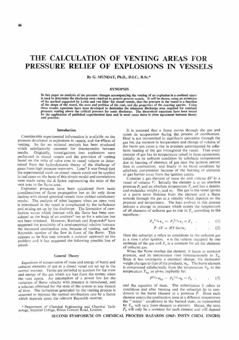
In the one-dimensional theory a similar treatment of the problem is pursued. The centre of ignition is made the origin of the system and the two ends of the vessel are identified by the subscripts + and — as shown in Fig. 1. Coefficients Su
+, Sb+, Su~~ and Sb~ are introduced to account for cases where venting of either unburnt or burnt gases occurs at the positive or negative ends. The coefficients have the value one if venting occurs and zero when it does not. Hence, the mass balance on the unburnt gas is :
(1 - » ) = [! -(Xf+-Xf-)1 P1,Yu
+ -jr(Stt+ + Jt.
ajfiYu+msvJ dt (17)
where x — XIL a n d t h e o t h e r symbols have the same meaning as before.
Centra of
End ignition
Flamas tota l a r«a
A • End
Fig. I.—One-dimensional combustion model
In considering the burnt gas vented it is necessary to introduce the term:
F = He lib]
which characterises the state of the burnt gas which is being vented. Then, the mass balance on burnt gas is:
TTli Xf rP
+?,-£<*++*-a / J(y6+l)/(2r6)
F * -dt ;is)
When Xb = Yu ~ Y> t^ ie e n e r §y balance can be written:
P + in S*++Su- + -*{Sb++Sb-)lF*
l+b^
m
'Xf * P
a / , (3y- l ) / (2r) d t
h
\p^r g+-£(sb++sb-)FPo-* Jxr rp ^
J; X xplr+VKM dt ;t9)
The equation for the rate of combustion is obtained by making the assumption that the flame is instantaneously established as a plane across the vessel section. If ignition is at one end of the vessel a single flame is formed but if it occurs within the vessel two flames propagate in opposite directions and the flame area is doubled.
Then:
dn dt w( 'Af*' \A,
ii; (20)
if the correct value is assigned to {Af/A^). The solution of equations (18), (19) and (20) for Yu=yb = Y
is:
dn H Af
and:
(Xf+~Xf~)P
= [l-(Su++Su-)IS]p-(l-n)p°
+ {l + nb)(Su++Su-)fS
121:
SECOND SYMPOSIUM ON CHEMICAL PROCESS HAZARDS (1963: INSTN CHEM. ENGRS)
MUNDAY. THE CALCULATION OF VENTING AREAS 49
ONE VENT
AV = A0
T W O VENTS
AV = 2A0
CENTRAL IGNITION
h—end - fend
X
L-2 Flames Af = 1AQ
Unburnt gas vented t i l l flame reaches vent when burnt gas is vented.
A,JA, = 2
S= \ or
s> I
—end +enc
1 1 2 Flames Af = 2A0
Unburnt gas yented.
s„- = s, + = i sb- = sb+ = o A//A. = 1
S = 1
OPEN END IGNITION
— end +end
1 X [_
1 F lame Af = A0
Burnt gas vented.
Sf = 1 S, r = SB+ = S6- = 0
A//A, = 1
S > 1
—end +end
fx ' J 1 Flame Af — A„
Both burnt and unburnt gas vented.
sb- = s, + = i s6+ = s„- = o V A „ = l / 2
S > 1
CLOSED END IGNITION
— end +end
X
1 Flame Af = A0
Unburnt gas vented.
su~ = i s„+ = sb- = s,+ = o A,/A. = 1
S = 1
Definitions of coefficients
s,r su-sb-r sb-. For hemispherical flames values of AfjAv should be doubled. A0 = cross-sectional area of vessel.
Fig. 2.—Definitions of coefficients, and areas for one-dimensional combustion
where: S = Su++ Su~+ —« (Sb++ Sb~)lF*
This result assumes that Fpo does not alter with time. The eiTor introduced is small and for constant pressure venting is zero.
Av = maximum area for venting and distinguishes between the cases in which one or both ends are used. Fig. 2 illustrates five possible systems and gives values for the coefficients and flame area in each case.
Comparison with Experimental Results
Equations (15), (16), and (21) predict the behaviour of gaseous explosions in closed and vented vessels. By solving these equations the theory can be examined in the light of experimental evidence. In most cases, the solution requires a step-by-step calculation using a finite difference method, and each case must be considered separately. Only three experimental studies have been examined and, although these are primarily concerned with the venting of explosions the results for closed vessels will be considered first.
Pentane-air explosions in a nearly spherical vessel0
These experiments were carried out to determine the effectiveness of vents for the relief of explosions. Unfortunately, the results are either for venting pressures less than critical or for spring-loaded valves about which insufficient information is given. Therefore only the closed vessel results have been used and a theoretical pressure-time curve constructed for the explosion assuming the vessel to be approximately spherical.
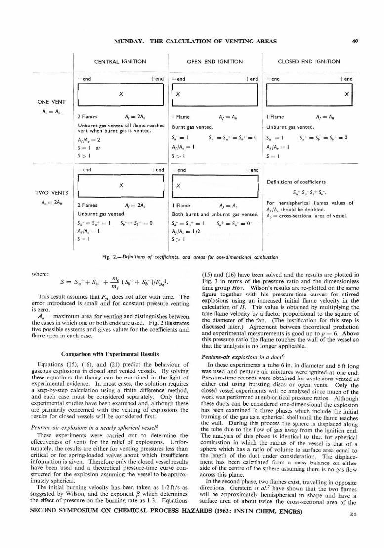
The initial burning velocity has been taken as l-2ft/s as suggested by Wilson, and the exponent /3 which determines the effect of pressure on the burning rate as 1-3. Equations
(15) and (16) have been solved and the results are plotted in Fig. 3 in terms of the pressure ratio and the dimensionless time group Hbr. Wilson's results are re-plotted on the same figure together with his pressure-time curves for stirred explosions using an increased initial flame velocity in the calculation of H. This value is obtained by multiplying the true flame velocity by a factor proportional to the square of the diameter of the fan. (The justification for this step is discussed later.) Agreement between theoretical prediction and experimental measurements is good up to p = 6. Above this pressure ratio the flame touches the wall of the vessel so. that the analysis is no longer applicable.
Pentane-air explosions in a duct6
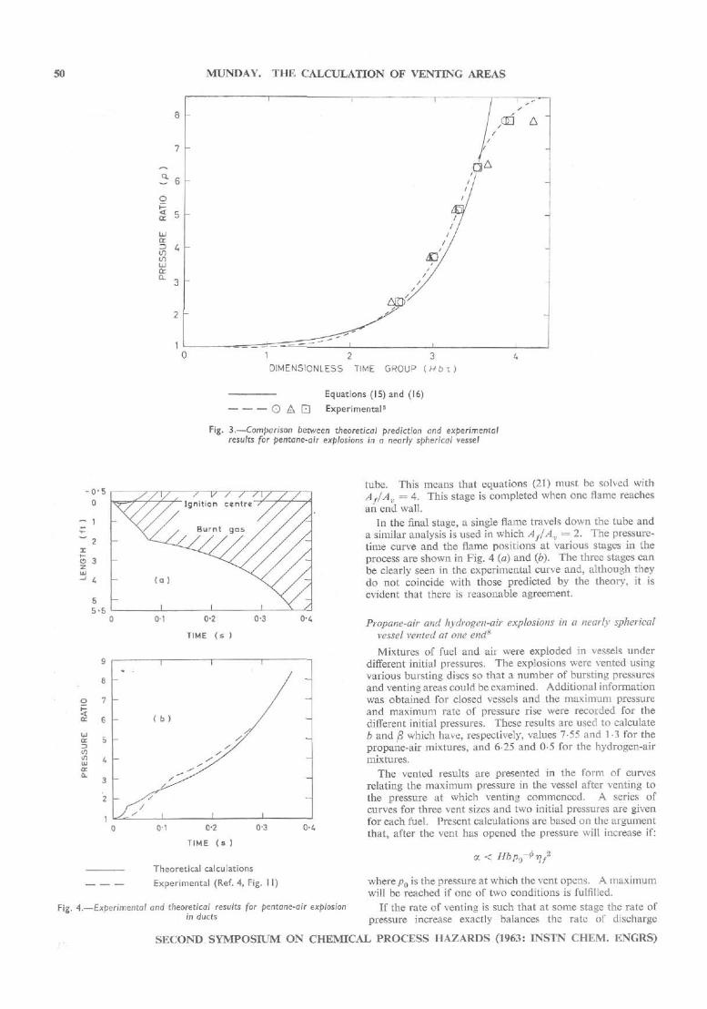
In these experiments a tube 6 in. in diameter and 6 ft long was used and pentane-air mixtures were ignited at one end. Pressure-time records were obtained for explosions vented at either end using bursting discs or open vents. Only the closed vessel experiments will be analysed since much of the work was performed at sub-critical pressure ratios. Although these ducts can be considered one-dimensional the explosion has been examined in three phases which include the initial burning of the gas as a spherical shell until the flame reaches the wall. During this process the sphere is displaced along the tube due to the flow of gas away from the ignition end. The analysis of this phase is identical to that for spherical combustion in which the radius of the vessel is that of a sphere which has a ratio of volume to surface area equal to the length of the duct under consideration. The displacement has been calculated from a mass balance on either side of the centre of the sphere assuming there is no gas flow across this plane.
In the second phase, two flames exist, travelling in opposite directions. Gerstein et al? have shown that the two flames will be approximately hemispherical in shape and have a surface area of about twice the cross-sectional area of the
SECOND SYMPOSIUM ON CHEMICAL PROCESS HAZARDS (1963: INSTN CHEM. ENGRS) E l
MUNDAY. THE CALCULATION OF VENTING AREAS
1 2 3
DIMENSIONLESS TIME GROUP {Hbx
Equations (15) and (16)
O A • Experimental5
Fig. 3.—Comparison between theoretical prediction and experimental results for pentane-air explosions in a nearly spherical vessel
-o-0
Z 1
~ 2 x S 3
...
"
...
-
~//Y/,y.v y < yy//y / / / / Ignit ion centre / / /
\( / / Burnt gas / / / /
( a ) ^ \ / / /
I I I \ / 0-1 0-2
TIME (s )
0-3 0-4
y
8
7
6
5
4
3
2
»
-
-
I
( b )
/ ^
i
i I
I I
/ — -
-
_
-
"
o-i 0-2
TIME (s )
0-3 0-<
Theoretical calculations
Experimental (Ref. 4, Fig. I I)
4.—Experimental and theoretical results for pentane-air explosion in ducts
tube. This means that equations (21) must be solved with Af/Av = 4. This stage is completed when one flame reaches an end wall.
In the final stage, a single flame travels down the tube and a similar analysis is used in which Af/Av = 2. The pressure-time curve and the flame positions at various stages in the process are shown in Fig. 4 (a) and (b). The three stages can be clearly seen in the experimental curve and, although they do not coincide with those predicted by the theory, it is evident that there is reasonable agreement.
Propane-air and hydrogen-air explosions in a nearly spherical vessel vented at one end8
Mixtures of fuel and air were exploded in vessels under different initial pressures. The explosions were vented using various bursting discs so that a number of bursting pressures and venting areas could be examined. Additional information was obtained for closed vessels and the maximum pressure and maximum rate of pressure rise were recorded for the different initial pressures. These results are used to calculate b and /3 which have, respectively, values 7-55 and 1-3 for the propane-air mixtures, and 6-25 and 0-5 for the hydrogen-air mixtures.
The vented results are presented in the form of curves relating the maximum pressure in the vessel after venting to the pressure at which venting commenced. A series of curves for three vent sizes and two initial pressures are given for each fuel. Present calculations are based on the argument that, after the vent has opened the pressure will increase if:
a < Hbp0-tr]f2
where p0 is the pressure at which the vent opens. A maximum will be reached if one of two conditions is fulfilled.
If the rate of venting is such that at some stage the rate of pressure increase exactly balances the rate of discharge
SECOND SYMPOSIUM ON CHEMICAL PROCESS HAZARDS (1963: INSTN CHEM. ENGRS)

MUNDAY. THE CALCULATION OF VENTING AREAS 51
VENT AREA TERM (-fi%''-'')
Equation (15)
Equation (22)
Fig. 5.—Maximum pressure ratio, pm, after venting at a pressure ratio p0 for propane-air explosions
through the vent, then:
dp An
= 0
and:
sound and viscosity of the reactants and the vent diameter respectively. Similarly, the corrected flame velocities used to calculate the pressure-time curves for Wilson's experimental data were a function of fan diameter, D, and the correction
Pm — {Hfj - If2!**-) * • • (22) factor can be related to the Reynolds number °- as shown
In this case, the maximum pressure is almost independent of the pressure at which the vent opens. Maximum pressure ratios calculated from this equation have a magnitude less than two except in the case of very small vent areas (the dotted curve in Fig. 5).
In the other condition the gas continues to burn until some part of the flame reaches the vent and the resulting reduction in flame area causes the pressure to fall. The maximum pressure will depend upon the pressure at which the vent opens because the distance between the flame and the vent at this instant governs the fuel available for further combustion and hence determines the total pressure increase. The calculation of the maximum pressure requires the step-by-step solution of equation (15) for different values of/?0 and a,, the maximum pressure being that corresponding to rjf = 1-0. The results of these calculations are shown in Figs. 5, 6, and 7.
In Fig. 5 the maximum pressure is related to vent area for a series of values of the operating pressure. The diagram has been calculated using yS = 1-3 for propane-air mixtures. The diagram can be used for any initial pressure and any vessel which is approximately spherical. Using these results, the variation of maximum pressure with vent opening pressure for three vent areas and two initial pressures have been calculated and compared, in Fig. 6, with the results obtained by Cousins and Cotton.8 For each curve the value of H has been calculated using a corrected value of the initial flame velocity to allow for the influence of turbulence. The results of similar calculations for hydrogen-air mixtures in which /S = 0-5 are shown in Fig. 7.
The correction factors for the initial flame velocities are plotted in Fig. 8 as a function of the Reynolds number given by a{ p{ d/fx{, where a{, y.{ and d are the initial velocity of
in the same figure. (N is the speed of rotation of the fan.) This argument is reinforced by the work of Rasbash and
Rogowski,4 Although the results cannot be used as a direct check because the venting pressures are too low, it is interesting to note that the authors suggest that there is a relation between the increased rate of combustion due to venting and the Reynolds number of flow ahead of the flame. These results are also plotted in Fig. 8.
An interesting point can be noted here. The theoretical analysis predicts that the correlation between maximum pressure and venting pressure ratios should be based on the term / = a./(Hb) and not on a alone. This result can be tested by examining the correlations for two systems in which the effect of initial pressure on burning velocity (and hence H) is reversed. Thus, with propane-air there is a decrease in burning velocity with an increase in pressure whereas with hydrogen-air the opposite is true to almost exactly the same extent. The agreement between the results at the two initial pressures is therefore significant.
" Safe " Venting Areas
If the pressure in the vessel is not to exceed the pressure at which the vent opens a criterion for " safe venting " can be defined by
(T) <* (23)
In spherical combustion the vent area ratio, ac, at which this, occurs is given by:
SECOND SYMPOSIUM ON CHEMICAL PROCESS HAZARDS (1963: INSTN CHEM. ENGRS)

52 MUNDAY. THE CALCULATION OF VENTING AREAS
E
a.
1 1 1
( b )
*-<H) /
(iii)
I 1 l
l 1 I
1 I 1
I
-
—
:
:
(a) Pi= I5lb/in :
O A • J, values used in calculation
(o) <i) 0-27
(ii) 0-35 {i i i) 0-50
(b) 0-12 0-20 0-30
Experims ntal values8
Experimental vent diameter (ft)
0-051 G 0-075 A 0-117 Q
O A . Q
J, values used in calculation
(a) (b) (i) 0-049 0-027
(ii) 0-084 0-049 (iii) 0-148 0-114
(b) P{ = 45 lb / in 2
Theoretical calculations
Experimental values8
Experimental vent diameter (ft)
0-051 O 0-075 A 0-117 Q
Fig. 6.—Maximum pressure reached in vented propane-air explosions p i g . 7.—Maximum pressure reached in vented hydrogen-air explosions
Hence the vent area will have to change as the flame radius increases. However, as is shown in Appendix 2, the pressure will decrease, irrespective of the increase in flame area if:
occ > HbPo-^ (24)
In the one-dimensional explosions safe venting is achieved when:
= Hbf.p0-*fS • (25)
The flame area is constant but the value of S can change if burnt gas is being vented. Since 5 ^ 1 ,
ac = Hb -J' • Po~ • (26)
gives the criterion for safe venting which is applicable to the worst case. Af/Av depends upon the number of vents used and the number of flames. Further, the flame area should be taken as twice the cross-section of the duct. (The values
given in Fig. 2 should be doubled since they have been calculated on the basis of a plane, and not hemispherical, flame.)
It can be shown that these two expressions for safe venting can be summarised in the statement that the ratio of the volumetric rate of discharge to the volumetric rate of burning must equal the ratio of the combustion energy to the compression energy in the unburnt gas.
In order to calculate safe venting areas from equations (24) and (26) information concerning the combustion system, and the relative position of the vent and the ignition centre is required.
(i) The information concerning the nature of the explosive mixture is best obtained experimentally using a spherical vessel with central ignition. The final pressure ratio, pe, and the maximum rate of pressure increase, (dp/dt)m, can be measured and used to calculate b and fi from:
b = p.~\
SECOND SYMPOSIUM ON CHEMICAL PROCESS HAZARDS (1963: INSTN CHEM. ENGRS)

MUNDAY. THE CALCULATION OF VENTING AREAS 53
0 - 5
fa-R.
\Sphericat O-l / vessels
-fa R,
REYNOLDS NUMBER
0 Circular ducts4
A v'ery small vent in circular duct4
• Square ducts4
"Spherical " vessel, propane-air: • = 4 5 l b / i n 2 (Ref. 8) + = 15 l b / i n 2 (Ref. 8)
"LSpherical " vessel, hydrogen-air: A = 4 5 l b / i n 2 (Ref. 8) O = 15 l b / i n 2 (Ref. 8)
Reynolds number based on f low ahead of the flame,
Reynolds number based on f low through vent, faR„
I Reynolds number based on j f low vent, faRel
Stirred explosion in " spherical " vessel5 Q Reynolds number based on fan diameter, and speed of rotat ion, ftxRe
Fig. 8.—Flame velocity correction
and:
-£*/«• where 5",-* = fundamental burning velocity under initial conditions.
The corrected initial flame velocity, / . $",•*, used in the calculation of H^fSf/C, is determined empirically and, since experimental figures are not yet available, it is suggested that it should be related to the Reynolds number as shown in Fig. 8. The choice of Reynolds number will depend largely on the shape of the vessel and the size of the vent. For large spherical vessels the vent will be the controlling factor, and the Reynolds number should be based on the flow through the vent. For ducts the Reynolds number of flow ahead of the flame should be used. Further, it is tentatively suggested, on the results for propane-air and hydrogen-air mixtures, that the relation between burning velocity and Reynolds number is dependent on the system of gases. This is in agreement with the work discussed by Lewis and von Elbe9 which shows that the burning velocity is a function of Reynolds number or its square root depending on the scale of turbulence and that the relationship also depends on the system of gases under consideration. These conclusions are for flames on burners. Hence, correlations for other reactants are required based on experimental results for vented explosions.
(ii) The relative position of vent and ignition centre will determine the value of S in equation (25). S is greater than one when burnt gas is vented and equal to one when un-burnt gas is vented. Hence, the vent should be placed as near to ignition centres as possible.
Conclusions
The analysis outlined above can be used to explain the venting of explosions with a reasonable degree of accuracy but confirmation is required for the correlation between burning velocity and Reynolds number. Other factors such as pressure oscillations and pressure drops along ducts have not been considered. However, it is suggested that the equations derived above give realistic values for safe venting areas and that future experimental work should be canalised along these lines.
There are two main advantages in this method. Primarily, the analysis is based, from first principals, on mass and energy balances, only employing an empirical relationship to account for the effect of turbulence because of venting. The assumed correlation between increased burning velocity and the relevant Reynolds number is supported to some extent by analogy with diffusion flame results and is more satisfactory than ad hoc relationships between maximum pressure and vent area.
Secondly, the experimental results are correlated so as to be applicable to any initial pressure and any shape of vessel. The correlation is such that a " safe " venting area can be defined and a simple equation can be used to calculate its value for any required venting pressure.
APPENDIX I
It is required to solve equation (14). Since the conditions are for constant pressure venting, the factor ptVu-tyYu in the first term on the right-hand side of the equation can be taken into the integral without appreciable error. Further, this integral is multiplied by (yb—yu)/(yb—l) and hence is small compared with the term containing the second integral.
Differentiating this result with respect to n:
b 1 / r »+(i -«)(n-yJ /yJ^
pVr* + Yu~ 1 H-nf
p[(3y„-l)/(2y„)]-v?
rjf is then obtained using this result and equation (13) to eliminate the integrals from the two equations (11), and equation (12). Hence:
y« - i Yb
prj/ = 1 + nb - (1 - n) /><r„-D/r„ Yb ~Yu p.
The two equations given in this appendix can be solved simultaneously by a step-by-step process.
APPENDIX II
Safe venting area for " spherical " explosions.
dp 6.ii
<4 ^, — a
// P' Vf
SECOND SYMPOSIUM ON CHEMICAL PROCESS HAZARDS (1963: INSTN CHEM. ENGRS)

54 MUNDAY. THE CALCULATION OF VENTING AREAS
If *l{Hb) = p0-+
35L- * - * - •>« • . and the pressure will fall. At some pressure dp/dn will change sign and the pressure will rise. However, p cannot increase above p0 because, as this value is approached, dp/dn must become negative again.
If <x./(Hb) = pQ~^ rjfo2, where rjfo is the flame radius when
the vent opens, the pressure may increase above p0 as the flame expands. Also, this may occur if:
Po~*Vf0* * « / (#*) < p<r*
Hence, the only true definition for " safe " venting area is:
ac = Hbp<r*.
References 1 Lewis, B., and von Elbe, G. " Combustion, Flames, and
Explosions", 1935, p. 160 (London: interscience Publishers).
Burgoyne, J. H., and Wilson, M. J. C ; Rasbash, D. J., and Rogowski, Z. W.; Simmonds, W. A., and Cubbage, P. A., in Rottenberg, P. A. (Ed.). " Symposium on Chemical Process Hazards with Special Reference to Plant Design ", 1960 (London: The Institution of Chemical Engineers).
Munday,G. Ph.D. Thesis, 1961, p. 253. University of London. Rasbash, D. J., and Rogowski, Z. W. Combustion and Flame,
1960, 4, 301. Wilson, M. J. G. Ph.D. Thesis, 1954. University of London. Rasbash, D. J., and Rogowski, Z. W. Fire Research Estab
lishment, 1956, Note FR 298. Gerstein, M., Carlson, E. R., and Hill, F. U. Industr. Engng
Chem., 1951,46,2558. Cousins, F. W., and Cotton, P. E. Chem. Engng, 1951, 58,
133. Lewis, B., and von Elbe, G. " Combustion, Flames, and
Explosions", 1935, p. 492 (London: Interscience: Publishers).
The manuscript of this paper was received on 25 March, 1963.
SECOND SYMPOSIUM ON CHEMICAL PROCESS HAZARDS (1963: INSTN CHEM. ENGRS)