The Buyers’ Guide to: Trussed Rafters€¦ · Trussed rafters are a specific type of roof truss,...
24
The Buyers’ Guide to: Trussed Rafters
Transcript of The Buyers’ Guide to: Trussed Rafters€¦ · Trussed rafters are a specific type of roof truss,...
The Buyers’ Guide to:
Trussed Rafters

page 01The Buyers’ Guide to Trussed Rafters
These highly engineered products, manufactured in factory-controlled conditions, offer a range of benefits:
• Suitable for a wide range of roof structures and shapes • Can be used with masonry, timber frame or steel frame construction• Prefabricated components mean reduced labour costs• Speed of construction allows just-in-time delivery to site• Made of timber, the only truly renewable building resource• Minimal environmental impact for manufacturing and installation• Manufactured using the latest software to meet the requirements of Eurocode design
Trussed Rafter Association (TRA) members create bespoke designs for all types of home builders, from major
volume housebuilders to individual self and custom builders and community self-build projects. Many members can also help with supply and fit, or supply, fit and finish services according to your needs and budget.
A number of TRA members specialise in commercial trussed rafters, supplying roofs for hospitals, supermarkets, schools and many other large public projects, and designed to Eurocode 5 for best practice structural integrity.
We’ve produced this buyers’ guide to outline the wide range of roof types that can be built with trussed rafters and to highlight the key considerations when choosing trussed rafters to create your chosen roofscape.
To find out more, visit www.tra.org.uk or www.traireland.ie to find a TRA member
near you who will be happy to advise you on the next steps for your trussed rafter roof.
About the TRAThe TRA is the respected voice of the trussed rafter and metal web joist industry in the UK and Ireland. We are committed to stringent standards of quality and service and set a professional benchmark for the industry.
Members include the principal manufacturers and suppliers of trussed rafters and metal web joists, and professionals involved in roof and floor design and construction.
The TRA requires all its manufacturing members to have third-party supervised quality assurance and professional indemnity insurance, helping to ensure quality and peace of mind for the customer.
Trussed rafters are a specific type of roof truss, providing an offsite manufactured structural framework to support the roof fabric, ceilings and often floors of buildings in both the domestic and commercial sectors.
Introduction
Contents
Responsibilities in roof design Examples of key design responsibilities Glossary of terms
Technical information1 Creating roofscapes with trussed rafters 2 Examples of basic trussed rafter profiles 3 Room in Roof trussed rafters 4 Storage of trussed rafters on site 5 Standard bracing of trussed rafter roofs 6 Loft hatch and chimney openings in trussed rafter roofs
Construction checklist
020304
080910131416
20Images courtesy of Pasquill, Wolf Systems, MiTek and Scotts of Thrapston

The roles of the Building Designer and Trussed Rafter DesignerAll TRA members use the latest software to design trussed rafters to comply with EN 1995-1-1 (Eurocode 5) and fabricate them in accordance with EN 14250: “Timber structures - Product requirements for prefabricated structural members assembled with punched metal plate fasteners”.
A third document PD 6693, or SR 70 in Ireland, sets out how this process takes place, by identifying the two critical people involved in the design stage, who are the building designer and the trussed rafter designer:
“On every project it is essential that one person assumes overall responsibility as building designer and is clearly defined as such.”
The building designer is usually an architect or structural engineer appointed by the client. For smaller projects, the building designer may be the main contractor. There is a clear definition of responsibilities within the standards, with the building designer being responsible for:
“…ensuring adequate provision is made for the stability of the building as a whole as distinct from, and in addition to the stability of individual components.”
As a trussed rafter design is two-dimensional, it is the building designer’s responsibility to ensure the stability of the three-dimensional roof as a whole. This means the trussed rafter designer details the individual trusses, but not the overall roof structure unless specifically engaged to do so.
Information sharing is key to the process and the responsibilities for designers can be found in sections 10.2 and 10.3 in SR 70.
Getting the design right on any part of a building is key and for roofing it’s essential that all involved with the design, manufacture and installation of the components to build a trussed rafter roof are working together effectively.
page 02 www.tra.org.uk
Responsibilities in roof design

To help meet the responsibilities set out above, detailed drawings and written instructions are always provided by TRA members as part of the truss delivery package. In addition to this specific technical information, TRA members can also provide guidance on the transport, handling, storage and installation of our products. Therefore, contractors and designers should always work closely from as early a stage as possible with their chosen TRA member.
Building Designer
Responsible for ensuring:
• Stability bracing to hold trusses in place• Wind bracing to ensure roof acts as rigid structure• Horizontal lateral support for vertical load bearing elements• Resist wind uplift of trussed rafters and wall plates• A check takes place on the information supplied by the trussed rafter designer to confirm trussed rafters supplied are suitable for their intended use
The building designer should provide the trussed rafter designer with the following information, preferably in the form of detailed technical drawings:
a The service use of the building with reference to any unusual environmental conditions, or preservative treatments required.b The height and location of the building with reference to snow load and any unusual wind conditions.c The pitch of the roof, plus spacing, span and profile of the trussed rafters.d The method of support and position of load-bearing supports.e The type or weights of roof tiles or covering, including sarking, insulation and ceiling materials.f Details of specific ancillary loads such as tanks, hoist tracks, electrical equipment and dormer construction.g The overhang of rafters at eaves and other eaves details.h The positions and dimensions of hatches, chimneys and other openings.i Any special requirement for minimum member thickness (e.g. for the purposes of fixing ceiling boards).
Trussed Rafter Designer
Responsible for ensuring:
• Roof load sustained and transmitted to supports• Individual members resist buckling
The trussed rafter designer should provide the building designer with the following information, preferably in the form of detailed technical drawings:
1 The loadings and other conditions for which the trussed rafters are designed.2 The positions and sizes of all bearings.3 The position and spacing of all trussed rafters.4 The sizes and strength classes of timber members.5 The type, size and positions of all punched metal plate fasteners.6 Details of any preservative treatments applied to timber members.7 The positions, fixings and sizes of any lateral supports necessary to prevent buckling of compression members of the trussed rafters.8 The location and method of support for tanks or ancillary equipment.9 The range of reactions (including for wind uplift) to be accommodated at the support positions.10 Any special precautions for handling, storage or installation.
page 03The Buyers’ Guide to Trussed Rafters
Examples of key design responsibilities (Check the standards PD 6693 and SR 70 for full details)

Apex/PeakThe uppermost point of a truss.
Attic trussA truss which forms the top storey of a dwelling, but allows the area to be habitable by leaving it free of internal web members. This will be compensated by larger timber sizes elsewhere.
BargeboardBoard fitted to conceal roof timbers at gable end.
BattensSmall timber members spanning over trusses to support tiles, slates etc.
BearerA member designed to distribute loads over a number of trusses.
BearingThe part of a truss receiving structural support. This is usually a wallplate, but can be an internal wall etc.
BinderA longitudinal member nailed to trusses to restrain and maintain correct spacing.
BirdsmouthA notch in the underside of a rafter to allow a horizontal seating at the point of support (usually with raised tie trusses).
BlockingShort timbers fixed between chords or between a chord and gable wall to prevent lateral movement. They should be at least 70% of the depth of the chords.
BobtailA truss type formed by truncating a normal triangular truss.
Bottom chordSee ceiling tie.
BracingThis can be temporary, stability or wind bracing which are described under these headings in this glossary.
Building designerThe person responsible for the structural stability and integrity of the building as a whole.
CamberAn upward vertical displacement built into a truss in order to compensate for deflection which might be caused by the loadings.
CantileverThe part of a structural member of a truss which extends beyond its bearing.
Ceiling tieThe lowest member of a truss, usually horizontal, which carries the ceiling construction, and to which storage loads and water tanks are applied.
Chevron bracingDiagonal bracing nailed to the truss in the plane of the specified webs to add stability.
Connector plate/fastenerSee nailplate.
Cripple rafterSee jack rafter.
Dead loadThe load produced by the fabric of the building, always long term (see design loads).
DeflectionThe deformation caused by the loads.
Design loadsThe loads for which the unit is designed. These consider the duration of the loads long term, medium term, short term and very short term.
Duo/dual pitch trussA truss with two rafters meeting at the apex, but not necessarily having the same pitch on both sides.
DwangsSee noggings.
EavesThe line where the rafter meets the wall.
Eaves jointThe part of the truss where the rafter and the ceiling tie intersect. This is usually where the truss is supported.
Extended rafterSee raised tie truss.
FasciaHorizontal board fitted along the length of the building to the edge of the truss overhangs.
FastenerSee nailplate.
Fink trussThe most common type of truss used for dwellings. It is duo pitch, the rafter having the same pitch. The webs form a letter ‘W’.
Firring pieceA tapered timber member used to give a fall to flat roof areas.
French heelAn eaves joint where the rafter sits on the ceiling tie.
Gable endThe end wall, which is parallel to the trusses and extends upwards vertically to the rafters.
Girder truss Two or more trussed rafters fixed together, designed to act as a single structural unit carrying exceptional loads such as those imposed by other trussed rafters fixed to it.
Hip endAn alternative to a gable end where the end wall finishes at the same height as the adjacent walls. The roof inclines from the end wall, usually (but not always) at the same pitch as the main trusses.
Hip setThe trusses, girders and loose timbers required to form a hip end.
HornAn extension of the ceiling tie of a truss (usually mono pitch or bobtailed trusses) which is built into masonry as a bearing.
Imposed loadThe load produced by occupancy and use including storage, inhabitants, moveable partitions and snow, but not wind. Can be long, medium or short term.
page 04 www.tra.org.uk
Glossary of terms
Internal memberSee webs.
IntersectionThe area where roofs meet.
Jack rafterAn infill rafter completing the roof surface in areas such as corners of hip ends or around chimneys.
Live loadTerm sometimes used for imposed loads.
Longitudinal bracingComponent of stability bracing.
Loose timberTimbers not part of a truss, but added to form the roof in areas where trusses cannot be used.
Mono-pitch trussA truss in the form of a right-angled triangle with a single rafter.
NailplateMetal plate having integral teeth punched from the plate material. It is used for joining timber in one plane with no overlap. It will have an accreditation certificate and will be manufactured, usually, from galvanised steel.
NibSee horn.
NodePoint on a truss where the members intersect.
NoggingsTimber pieces fitted at right angles between the rafters and ceiling ties to form fixing points.
OverhangThe extension of a rafter or ceiling tie of a truss beyond its support or bearing.
Part profileSee bobtail.
PeakSee apex.
Permissible stressesDesign stresses for grades of timber.
PitchThe angle of the rafter to the horizontal, measured in degrees.
PlateSee nailplate.
PurlinsTimber members spanning over trusses to support roof covering or between trusses to support loose timber members.
Quality Assurance SchemeEssential quality control method in truss manufacture administered by a UKAS registered notified body.
Quarter pointThe point on a rafter where the strut intersects in a fink truss.
QueenInternal member or web which connects the apex to a third point on a fink truss.
RafterThe uppermost member of a truss which normally carries the roof covering.
Rafter diagonal bracingComponent of stability bracing.
Raised tie trussA truss which is supported at a point on the rafter that is beyond the point where the rafter meets the ceiling tie.
Reducing trussesSee valley frames.
Remedial detailA modification produced by the trussed rafter designer to overcome a problem with the truss after its manufacture.
Return spanThe span of a truss being supported by a girder.
RidgeThe line formed by the truss apexes.
RidgeboardTimber running along a ridge and sandwiched between loose rafters.
Roof designerThe person responsible for the roof structure as a whole and who takes into account its stability and capability of transmitting wind forces on the roof to suitable load-bearing walls.
Room in Roof (RIR)See attic truss.
ScabAdditional timber fitted to the side of a truss to affect a local reinforcement, particularly in raised tie trusses.
Setting out pointThe point on a truss where the undersides of the rafter and ceiling tie meet.
Skew nailingA method of fixing trusses to the wallplate by driving nails at an angle through the truss into the wallplate, which is generally not recommended. (See truss clip).
SoffitBoard fixed underneath eaves overhang along the length of the building to conceal timbers.
SpanSpan over wallplates is the distance between the outside edges of the two supporting wallplates. This is usually the overall length of the ceiling tie.
Spandrel panelA timber frame, triangular panel forming a wall above ceiling line. Either as a party wall to provide fire compartmentalisation between dwellings or as a gable end wall.
SpliceA joint between two members in line using a nailplate.
Spreader beamSee bearer.
Stability bracingArrangement of additional timbers fixed in the roof space to provide lateral support for trussed rafters.
StrapMetal component designed to fix trusses and wallplates to walls.
page 05The Buyers’ Guide to Trussed Rafters
StrutInternal member connecting the third point and the quarter point on a fink truss.
Stub endSee bobtail. Temporary bracingEssential support installed for safety during initial stages of truss installation. Failure to correctly install effective temporary bracing creates a significant safety risk.
Third pointPoint on the ceiling tie where the internal webs meet in a fink truss.
Timber stress gradingThe classification of timber into different structural qualities based on strength.
Top chordSee rafter.
TrimmerA piece of timber used to frame around openings.
Trussed rafterA lightweight framework, generally but not always triangulated, placed at regular intervals to support the roof. It is made from timber members of the same thickness, fastened together in one plane using nailplates.
Trussed rafter designerThe person responsible for the design of the trussed rafter as a component and for specifying the points where bracing is required.
Truss clipA metal component designed to provide a safe structural connection of trusses to wallplates, in order to resist wind uplift and to prevent the damage often seen with skew nailing.
Truss shoeA metal component designed to provide a structural connection and support for a truss to a girder or beam.
Uniformly distributed loadA load that is uniformly spread over the full length of the truss member.
Valley boardA member raking from incoming ridge to corner in a valley construction.
Valley frames/setInfill frames used to continue the roofline when roofs intersect.
VergeThe line where the trussed rafters meet the gable wall.
WallplateA timber member laid along the length of the load bearing walls to support the trusses.
WebsTimber members that connect the rafters and the ceiling tie together, forming triangular patterns which transmit the forces between them.
Wind bracingAn arrangement of additional timbers or other structural elements in the roof space, specially designed to transmit wind forces to suitable load-bearing walls.
page 06 www.tra.org.uk
Glossary of terms (cont.)

Around 95% of all new house roofs are constructed using trussed rafters. This is in addition to an increasing proportion of offices, retail outlets, hospitals and leisure developments.
Trussed rafters can be used to construct a wide variety of roof shapes as outlined below.
However, this is by no means an exhaustive list. Every case is unique and you are advised to contact a TRA member as early as possible in a project to discuss a detailed solution.
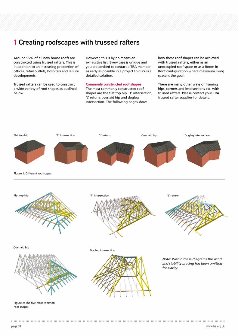
Commonly constructed roof shapesThe most commonly constructed roof shapes are the flat top hip, ‘T’ intersection, ‘L’ return, overlaid hip and dogleg intersection. The following pages show
how these roof shapes can be achieved with trussed rafters, either as an unoccupied roof space or as a Room in Roof configuration where maximum living space is the goal.
There are many other ways of framing hips, corners and intersections etc. with trussed rafters. Please contact your TRA trussed rafter supplier for details.
page 08 www.tra.org.uk
1 Creating roofscapes with trussed rafters
Figure 2: The five most common roof shapes
Figure 1: Different roofscapes
Note: Within these diagrams the wind and stability bracing has been omitted for clarity.
Flat top hip ‘T’ intersection ‘L’ return Overlaid hip Dogleg intersection
‘L’ return
Dogleg intersection
‘T’ intersection
Overlaid hip
Flat top hip
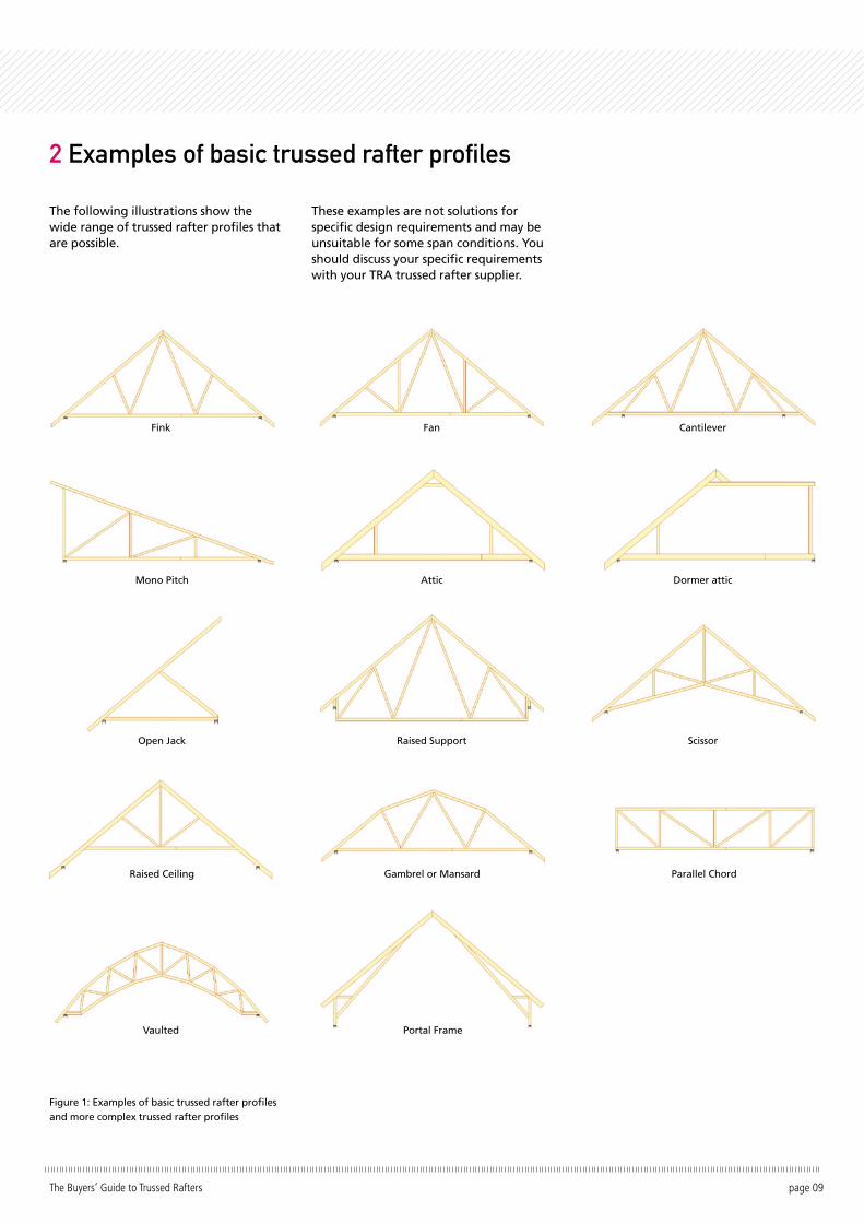
The following illustrations show the wide range of trussed rafter profiles that are possible.
These examples are not solutions for specific design requirements and may be unsuitable for some span conditions. You should discuss your specific requirements with your TRA trussed rafter supplier.
page 09The Buyers’ Guide to Trussed Rafters
2 Examples of basic trussed rafter profiles
Figure 1: Examples of basic trussed rafter profiles and more complex trussed rafter profiles
Fink
Mono Pitch
Open Jack
Raised Ceiling
Vaulted
Fan
Attic
Raised Support
Gambrel or Mansard
Portal Frame
Cantilever
Dormer attic
Scissor
Parallel Chord
The Room in Roof (RIR) or attic trussed rafter provides the structural roof and floor in a single component. There are many advantages:
• RIR trussed rafters are computer- designed and factory-assembled, resulting in better quality control• Complex, labour-intensive site joints are not required• They can be constructed very quickly, making the structure weather tight much sooner and resulting in cost savings• Customers have freedom to plan the room layout within the roof space• A complete structure is provided, ready to receive roof finishes, plaster board and floorboarding
The diagrams below (Figures 1 and 2) compare an eight-metre span standard trussed rafter with an equivalent eight-metre span RIR trussed rafter.
Typical Room in Roof configurations Room in Roof trussed rafters can usually be designed to clear span between the
front and rear walls of a dwelling without the need for building loadbearing walls and foundations on lower storeys. If internal loadbearing walls exist or can easily be built, they can be used to provide additional support.
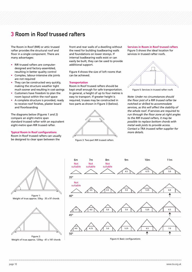
Figure 4 shows the size of loft rooms that can be achieved.
TransportationRoom in Roof trussed rafters should be kept small enough for safe transportation. In general, a height of up to four metres is easy to transport. If greater height is required, trusses may be constructed in two parts as shown in Figure 3 (below).
Services in Room in Roof trussed raftersFigure 5 shows the ideal location for services in trussed rafter roofs.
Note: Under no circumstances should the floor joist of a RIR trussed rafter be notched or drilled to accommodate services, as this will affect the stability of the whole roof. If services are required to run through the floor zone at right angles to the RIR trussed rafters, it may be possible to replace bottom chords with metal web joists to provide access. Contact a TRA trussed rafter supplier for more details.
page 10 www.tra.org.uk
3 Room in Roof trussed rafters
Figure 4: Basic configurations
Figure 5: Services in trussed rafter roofs
Figure 1: Weight of truss approx. 55kg - 35 x 97 chords
6m
4.5
5.0
5.0
5.25
4.5
5.0
5.0
4.0
4.0
4.75
3.5
4.0
4.75
5.25
5.25
6.5
5.0
6.0
6.5
7.0
Notsuitable
Notsuitable
Notsuitable
Notsuitable
7m 8m 9m 10m 11m
35º
40º
45º
50ºFigure 2:
Weight of truss approx. 125kg - 47 x 197 chords
Figure 3: Two-part RIR trussed rafters
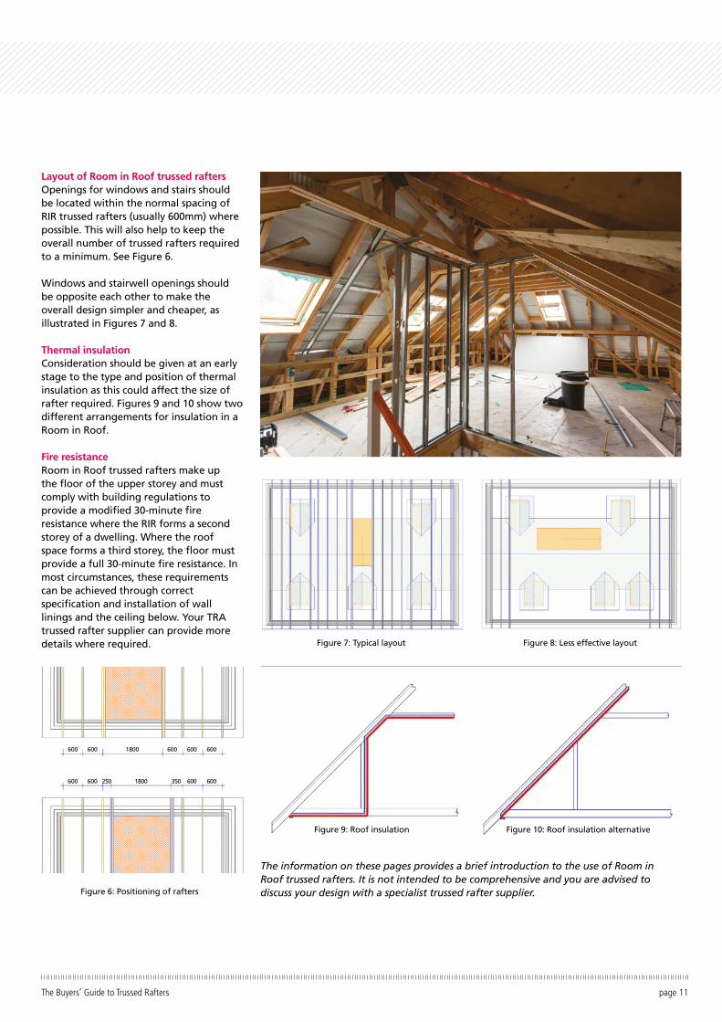
Layout of Room in Roof trussed raftersOpenings for windows and stairs should be located within the normal spacing of RIR trussed rafters (usually 600mm) where possible. This will also help to keep the overall number of trussed rafters required to a minimum. See Figure 6.
Windows and stairwell openings should be opposite each other to make the overall design simpler and cheaper, as illustrated in Figures 7 and 8.
Thermal insulationConsideration should be given at an early stage to the type and position of thermal insulation as this could affect the size of rafter required. Figures 9 and 10 show two different arrangements for insulation in a Room in Roof.
Fire resistanceRoom in Roof trussed rafters make up the floor of the upper storey and must comply with building regulations to provide a modified 30-minute fire resistance where the RIR forms a second storey of a dwelling. Where the roof space forms a third storey, the floor must provide a full 30-minute fire resistance. In most circumstances, these requirements can be achieved through correct specification and installation of wall linings and the ceiling below. Your TRA trussed rafter supplier can provide more details where required.
page 11The Buyers’ Guide to Trussed Rafters
Figure 6: Positioning of rafters
Figure 7: Typical layout Figure 8: Less effective layout
Figure 9: Roof insulation Figure 10: Roof insulation alternative
The information on these pages provides a brief introduction to the use of Room in Roof trussed rafters. It is not intended to be comprehensive and you are advised to discuss your design with a specialist trussed rafter supplier.
600
600
600
600 250 1800 350 600 600
600 600 6001800
page 12 www.tra.org.uk
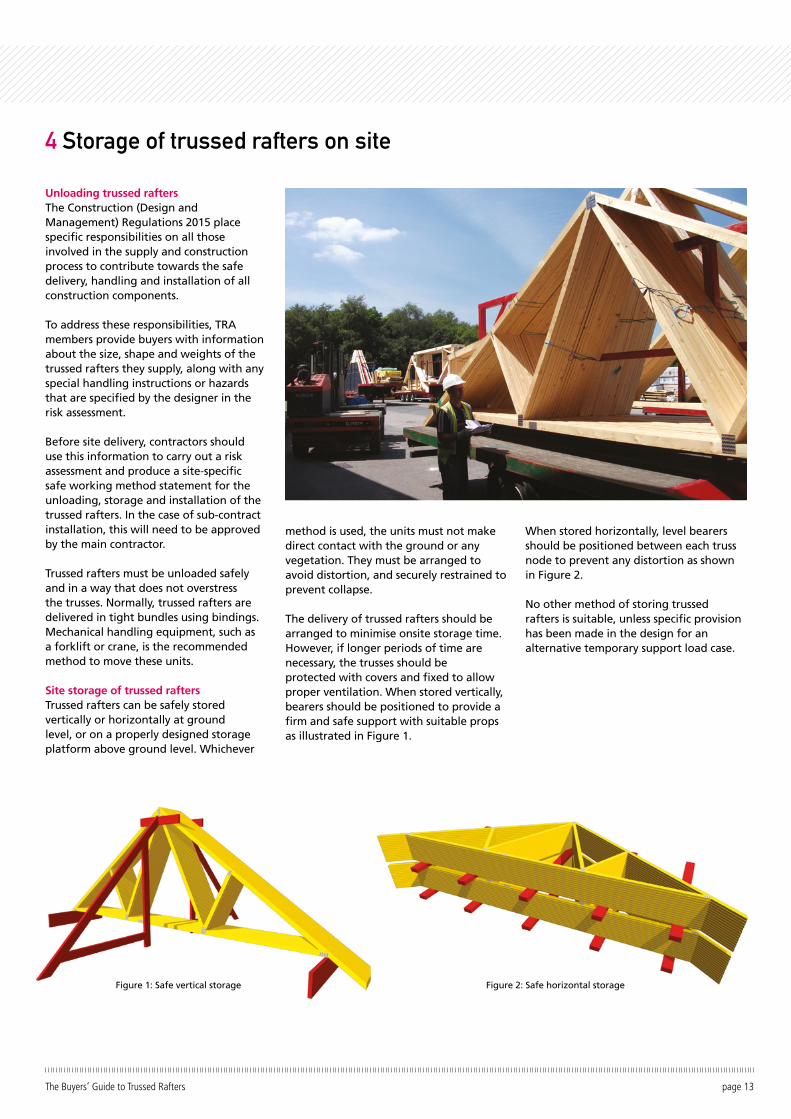
Unloading trussed raftersThe Construction (Design and Management) Regulations 2015 place specific responsibilities on all those involved in the supply and construction process to contribute towards the safe delivery, handling and installation of all construction components.
To address these responsibilities, TRA members provide buyers with information about the size, shape and weights of the trussed rafters they supply, along with any special handling instructions or hazards that are specified by the designer in the risk assessment.
Before site delivery, contractors should use this information to carry out a risk assessment and produce a site-specific safe working method statement for the unloading, storage and installation of the trussed rafters. In the case of sub-contract installation, this will need to be approved by the main contractor.
Trussed rafters must be unloaded safely and in a way that does not overstress the trusses. Normally, trussed rafters are delivered in tight bundles using bindings. Mechanical handling equipment, such as a forklift or crane, is the recommended method to move these units.
Site storage of trussed raftersTrussed rafters can be safely stored vertically or horizontally at ground level, or on a properly designed storage platform above ground level. Whichever
method is used, the units must not make direct contact with the ground or any vegetation. They must be arranged to avoid distortion, and securely restrained to prevent collapse.
The delivery of trussed rafters should be arranged to minimise onsite storage time. However, if longer periods of time are necessary, the trusses should be protected with covers and fixed to allow proper ventilation. When stored vertically, bearers should be positioned to provide a firm and safe support with suitable props as illustrated in Figure 1.
When stored horizontally, level bearers should be positioned between each truss node to prevent any distortion as shown in Figure 2.
No other method of storing trussed rafters is suitable, unless specific provision has been made in the design for an alternative temporary support load case.
page 13The Buyers’ Guide to Trussed Rafters
4 Storage of trussed rafters on site
Figure 2: Safe horizontal storageFigure 1: Safe vertical storage
The following guidelines apply to both standard trussed rafter roofs for dwellings and Room in Roof (Attic) trussed rafter roofs
Why brace trussed rafter roofs?Trussed rafters must be braced to create a rigid and stable roof structure. If the bracing is omitted, wrongly positioned or badly fixed, individual trusses may distort or fail and in some cases, the whole roof may fail.
Responsibility for bracingThe building designer is responsible for designing and detailing all elements of roof bracing, including that for trusses. The trussed rafter designer will inform the building designer of any truss integrity bracing required.
The functions of roof bracingRoof bracing performs three distinct functions:
Temporary bracing – restrains the trusses during construction.
Truss stability bracing – permanent bracing, which holds the trusses upright and prevents buckling.
Wind or wall bracing – permanent bracing in addition to truss stability bracing, which stabilises the gable walls under wind load.
Application of standard bracingTo assist building designers, the supporting documents to Eurocode 5, PD 6693 for the UK and SR 70 for Ireland, provide examples and guidance on standard methods of bracing for domestic scale trussed rafter and RIR roofs up to 12m in span.
Such standard methods of bracing are dependent on wind loads and building height. The table below provides some examples of allowable duo pitch truss spans in different wind zones in the UK. For Ireland wind speed is used to designate the wind zones and the alternative table overleaf provides some examples of allowable duo pitch truss spans.
Note: This method of bracing is not suitable for buildings on open stretches of country such as flat coastal fringes, fens, airfields or large open areas of fen, moor
or farmland, where additional calculations may be required.
Standard methods of bracing require certain conditions to be met, with the list below providing the main examples of the criteria. Buyers and Building Designers should always refer to PD 6693 for the UK and SR 70 for Ireland for full details of standard bracing methods.
• The maximum trussed rafter spacing is 600mm.• Floor to ceiling height no greater than 2.6m• 12.5mm plasterboard or similar rigid material ceilings fixed directly, or to continuous counter battens which are fixed directly to the bottom chords of the trussed rafters.• At least four rafter diagonal braces, two at each gable end, are laid at approx. 45° and fixed to the underside of rafters and the wall plate. • Further diagonal bracing to be added at intervals along the roof to ensure each truss is braced.• Longitudinal bracing is located at all node points including the apex but excluding support points (see Figures 2 and 3).• Chevron bracing should be included for duo-pitch spans over 8m.
• Bracing members to be nominal 25 x100mm with a minimum cross- sectional area of 2,134mm2 and a minimum target thickness of 22 mm. • All bracing members are nailed to every trussed rafter they cross with two 3.35mm diameter galvanized wire nails with a minimum length equal to the bracing thickness plus 32mm (36mm in Ireland). In all details 3.1mm diameter mechanically driven gun nails may be substituted.• Bracing members may be joined by overlapping at least two trussed rafters.• For masonry walls the maximum unsupported length must not exceed 9m between returns, buttresses or chimneys.
Other considerationsIf an insulation material is installed on top of the rafters, it may reduce the effect of the tiling batten restraint. In this case, additional bracing may be required underneath as specified by the trussed rafter designer.
Where there is no plasterboard, the ceiling tie members need to be braced at all nodes, and additional longitudinal braces may be required.
page 14 www.tra.org.uk
5 Standard bracing of trussed rafter roofs
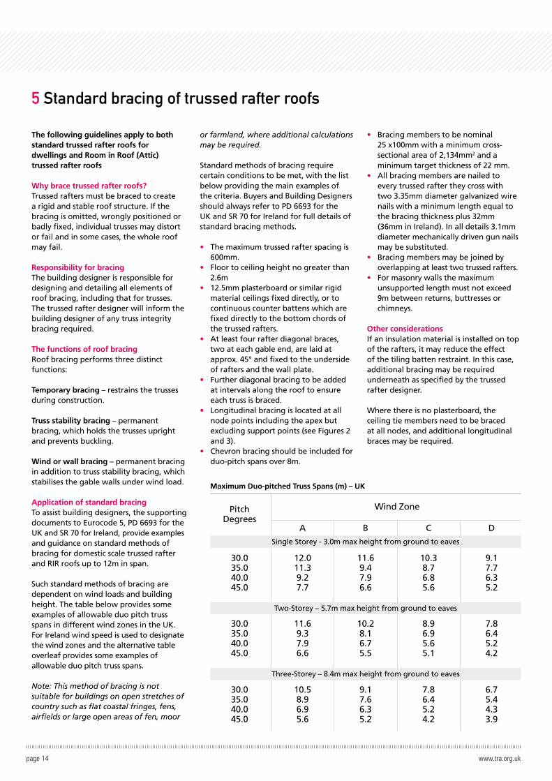
30.035.040.045.0
12.011.39.27.7
11.69.47.96.6
10.38.76.85.6
9.17.76.35.2
30.035.040.045.0
11.69.37.96.6
10.28.16.75.5
8.96.95.65.1
7.86.45.24.2
30.035.040.045.0
10.58.96.95.6
9.17.66.35.2
7.86.45.24.2
6.75.44.33.9
A B C D
Single Storey - 3.0m max height from ground to eaves
Two-Storey – 5.7m max height from ground to eaves
Three-Storey – 8.4m max height from ground to eaves
Wind ZonePitchDegrees
Maximum Duo-pitched Truss Spans (m) – UK
Pitch Degrees
30.035.040.045.0
< 25 m/s
12.012.010.38.7
< 26 m/s
12.010.68.97.4
< 27 m/s
11.69.87.66.3
30.035.040.045.0
12.010.58.97.4
11.59.17.56.2
11.69.87.66.3
30.035.040.045.0
11.810.07.76.3
10.28.57.15.8
8.87.25.94.7
page 15The Buyers’ Guide to Trussed Rafters
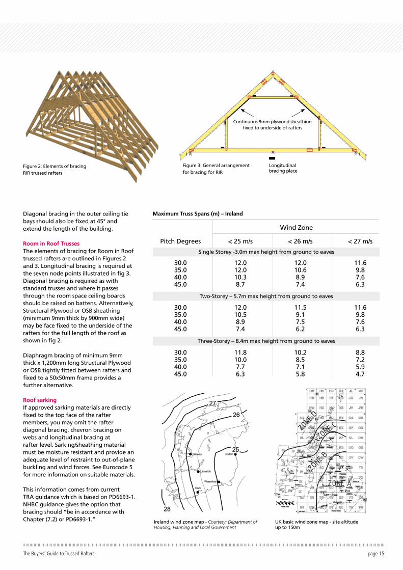
Figure 3: General arrangement for bracing for RIR
Continuous 9mm plywood sheathing fixed to underside of rafters
Longitudinal bracing place
Figure 2: Elements of bracing RIR trussed rafters
Single Storey -3.0m max height from ground to eaves
Two-Storey – 5.7m max height from ground to eaves
Three-Storey – 8.4m max height from ground to eaves
Wind Zone
Maximum Truss Spans (m) – IrelandDiagonal bracing in the outer ceiling tie bays should also be fixed at 45° and extend the length of the building.
Room in Roof TrussesThe elements of bracing for Room in Roof trussed rafters are outlined in Figures 2 and 3. Longitudinal bracing is required at the seven node points illustrated in fig 3. Diagonal bracing is required as with standard trusses and where it passes through the room space ceiling boards should be raised on battens. Alternatively, Structural Plywood or OSB sheathing (minimum 9mm thick by 900mm wide) may be face fixed to the underside of the rafters for the full length of the roof as shown in fig 2. Diaphragm bracing of minimum 9mm thick x 1,200mm long Structural Plywood or OSB tightly fitted between rafters and fixed to a 50x50mm frame provides a further alternative.
Roof sarkingIf approved sarking materials are directly fixed to the top face of the rafter members, you may omit the rafter diagonal bracing, chevron bracing on webs and longitudinal bracing at rafter level. Sarking/sheathing material must be moisture resistant and provide an adequate level of restraint to out-of-plane buckling and wind forces. See Eurocode 5 for more information on suitable materials.
This information comes from current TRA guidance which is based on PD6693-1. NHBC guidance gives the option that bracing should “be in accordance with Chapter (7.2) or PD6693-1.” Ireland wind zone map - Courtesy: Department of
Housing, Planning and Local GovernmentUK basic wind zone map - site altitude up to 150m
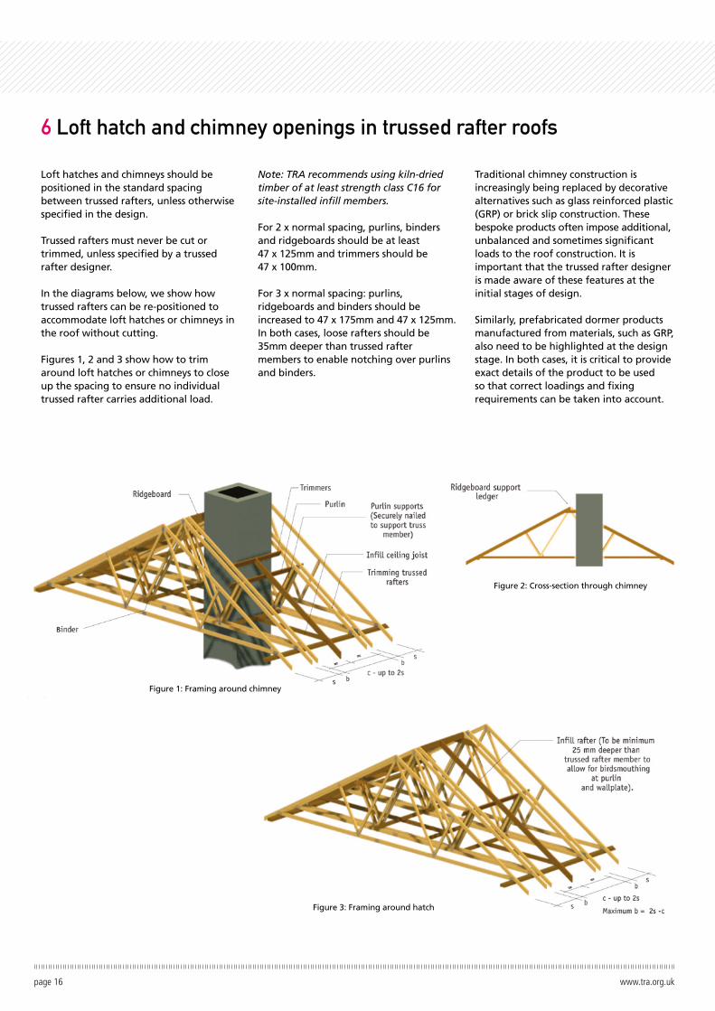
Loft hatches and chimneys should be positioned in the standard spacing between trussed rafters, unless otherwise specified in the design.
Trussed rafters must never be cut or trimmed, unless specified by a trussed rafter designer.
In the diagrams below, we show how trussed rafters can be re-positioned to accommodate loft hatches or chimneys in the roof without cutting.
Figures 1, 2 and 3 show how to trim around loft hatches or chimneys to close up the spacing to ensure no individual trussed rafter carries additional load.
Note: TRA recommends using kiln-dried timber of at least strength class C16 for site-installed infill members.
For 2 x normal spacing, purlins, binders and ridgeboards should be at least 47 x 125mm and trimmers should be 47 x 100mm.
For 3 x normal spacing: purlins, ridgeboards and binders should be increased to 47 x 175mm and 47 x 125mm. In both cases, loose rafters should be 35mm deeper than trussed rafter members to enable notching over purlins and binders.
Traditional chimney construction is increasingly being replaced by decorative alternatives such as glass reinforced plastic (GRP) or brick slip construction. These bespoke products often impose additional, unbalanced and sometimes significant loads to the roof construction. It is important that the trussed rafter designer is made aware of these features at the initial stages of design.
Similarly, prefabricated dormer products manufactured from materials, such as GRP, also need to be highlighted at the design stage. In both cases, it is critical to provide exact details of the product to be used so that correct loadings and fixing requirements can be taken into account.
page 16 www.tra.org.uk
6 Loft hatch and chimney openings in trussed rafter roofs
Figure 1: Framing around chimney
Figure 2: Cross-section through chimney
Figure 3: Framing around hatch
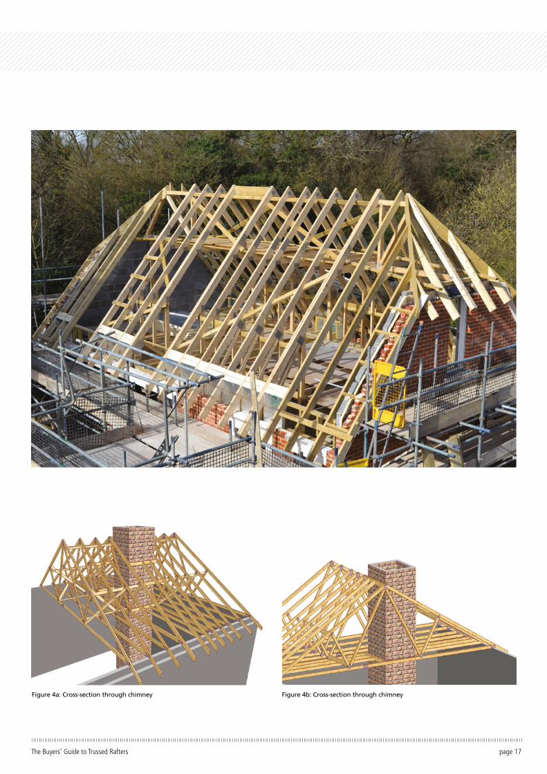
page 17The Buyers’ Guide to Trussed Rafters
Figure 4a: Cross-section through chimney Figure 4b: Cross-section through chimney
page 18 www.tra.org.uk
How to buy
We advise that you always speak to a TRA member to talk about your specific needs as early as possible in the project. They will be happy to discuss your requirements and to advise on the best approach for your project.
TRA members offer a range of services to suit your requirements. These are categorised as follows and you can choose the service(s) according to your project needs:
• Supply only• Supply and fit• Full roof design
Supply onlyThe supply-only service involves the customer supplying detailed project drawings directly to the TRA member, who then designs the trussed rafters using specialist software. Such project drawings will need to include the information listed in the ‘Examples of key design responsibilities’ section on page three of this guide. When the trussed rafter design
is completed, a copy will be provided to the customer for approval and once signed off, the TRA member will manufacture the trussed rafters to your specification and supply them to your site, at an agreed date and time. When choosing a supply-only service, you are then responsible for ensuring safe unloading and correct storage of the trussed rafters when they are delivered. You are also responsible for ensuring that the trussed rafters are properly installed by a suitably qualified person.
Supply and fitMany TRA members can provide a service that includes the manufacture, delivery and installation of trussed rafters.
With a supply and fit service, you have just one point of contact throughout your roof construction. Choosing this option gives you the peace of mind in knowing that those responsible for the installation are fully qualified specialist roofing joiners. In addition, the responsibility for developing
risk assessments and safe systems of work for storage and installation lies with your chosen TRA member.
Full roof designOn a bespoke basis, trussed rafter designers can take on more responsibilities for the roof design, if requested by the building designer or contractor.
Trussed rafters can be used for any shape and type of roof, regardless of how complex. A specialist trussed rafter designer will produce detailed designs to meet your requirements.
After discussing your project, the trussed rafter designer produces technical drawings using the latest software. Many TRA members also offer 3D visualisation, which is useful to help clients visualise unusual or complex designs. TRA members undertaking roof design will work to Eurocode 5 and provide structural design calculations and certificates for building control as required.
When you buy trussed rafters from a TRA member, you can be confident your supplier has been vetted and approved by the industry’s leading professional association.
To find a TRA member in your area, visit: www.tra.org.uk/search-members or www.traireland.ie. It couldn’t be easier to buy a trussed rafter roof to meet your exact specification.
QualityAll manufacturing members have registered with an independent quality assurance scheme to ensure their trussed rafters consistently meet the highest standards.
ReliabilityTRA members are committed to using the highest quality materials. All strength graded timber meets the requirements of EN 14081 and the metal plates EN 14545.
InsuranceEvery manufacturing member has professional indemnity (PI) insurance of at least £1 million.
Latest softwareTRA members use state of the art software to design trussed rafters and to meet your exact requirements.
SkilledRegular training sessions, seminars and online training courses are run to ensure TRA members have up-to-date knowledge and skills.
Complete serviceTRA members offer a complete package, from feasibility to final design and supply service, no matter how simple or how complex the roof design.
Environmentally responsibleMany TRA member companies are independently assessed against chain of custody standards to demonstrate they supply wood products derived only from sustainable forests under the Forest Stewardship Council (FSC) and Programme for Endorsement of Forest Certification (PEFC) frameworks.
Peace of mindAll members are committed to the TRA’s stringent standards of quality and service.
page 19The Buyers’ Guide to Trussed Rafters
With a TRA member, you are guaranteed the following:
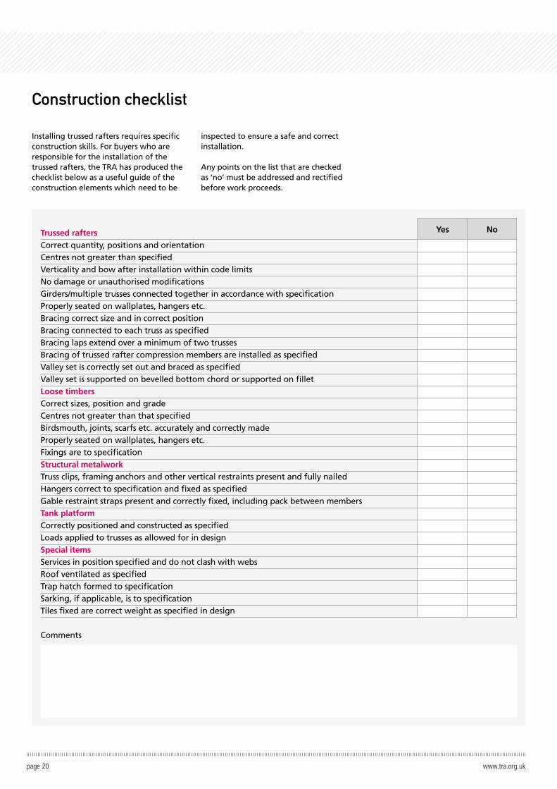
Construction checklist
Installing trussed rafters requires specific construction skills. For buyers who are responsible for the installation of the trussed rafters, the TRA has produced the checklist below as a useful guide of the construction elements which need to be
inspected to ensure a safe and correct installation.
Any points on the list that are checked as ‘no’ must be addressed and rectified before work proceeds.
Trussed raftersCorrect quantity, positions and orientation Centres not greater than specified Verticality and bow after installation within code limits No damage or unauthorised modifications Girders/multiple trusses connected together in accordance with specification Properly seated on wallplates, hangers etc. Bracing correct size and in correct position Bracing connected to each truss as specified Bracing laps extend over a minimum of two trusses Bracing of trussed rafter compression members are installed as specified Valley set is correctly set out and braced as specified Valley set is supported on bevelled bottom chord or supported on fillet Loose timbers Correct sizes, position and grade Centres not greater than that specified Birdsmouth, joints, scarfs etc. accurately and correctly made Properly seated on wallplates, hangers etc. Fixings are to specification Structural metalwork Truss clips, framing anchors and other vertical restraints present and fully nailed Hangers correct to specification and fixed as specified Gable restraint straps present and correctly fixed, including pack between members Tank platform Correctly positioned and constructed as specified Loads applied to trusses as allowed for in design Special items Services in position specified and do not clash with webs Roof ventilated as specified Trap hatch formed to specification Sarking, if applicable, is to specification Tiles fixed are correct weight as specified in design
Comments
Yes No
page 20 www.tra.org.uk
Site Certification in Ireland
The regulations place legal obligations on various parties to produce compliant buildings that are safe for occupants. These include additional responsibilities and duties on all parties to the building contract. Designers, specifiers, suppliers, specialist sub-contractors, installers and inspectors are “Ancillary Certifiers”.
TRA Ireland members fully recognise they have a role to play in this process in terms of the design and supply of trussed rafters, and metal web joists. These products fall within the Construction Products Regulations (CPR) and therefore are fully CE marked and supported by the appropriate Declarations of Performance. In addition, TRA Ireland members have professional indemnity insurance to cover the design aspects for which they are responsible.
Trussed rafters are most often undertaken on a design and supply only contract. On this basis TRA Ireland members provide as part of the documentation pack all of the required information to support the design and supply of their products in accordance with EN 14250 and the CPR. In addition, where required, members can provide signed copies of Ancillary Certificates in relation to design only e.g. the current SD and SC certificates endorsed by bodies such as RIAI and Engineers Ireland.
However, as TRA members have no control over the installation or overall performance of the roof structure they will not and are under no obligation to provide a signed copy of the SI certificate, or any form of signed certification that relates to installation. A separate contract
of engagement may be put in place for TRA Ireland members to provide such additional inspection services, at an additional charge.
To assist contractors to undertake their own inspection a construction checklist for trussed rafters is provided on page 20.
Alternatively, some TRA Ireland members offer trussed rafters on supply and fit contract terms which will include the provision for installation certificates such as the current SI form.
www.traIreland.ie
Rules covering compliance in building works were introduced in Ireland in April 2014.
Visit our website for more information: tra.org.uk
The Building Centre26 Store StreetLondonWC1E 7BT T: 020 3205 0032E: [email protected] The latest version of this guide can be downloaded online at tra.org.uk or traireland.ie All information is correct at the date this guide was produced. We reserve the right to make technical changes at any time.
ref:0005