
The Busy Bee - instrutechinc.com · 1.1 Description The PCM301 Busy Bee ™ vacuum gauge module...
34
p/n 002663-100 InstruTech® Pirani Capacitance Combination Vacuum Gauge PCM301 Module The Busy Bee™ User Manual InstruTech 1475 S. Fordham St. Longmont, CO 80503 USA Phone: +1-303-651-0551 Fax: +1-303-678-1754 E-mail [email protected] www.instrutechinc.com
Transcript of The Busy Bee - instrutechinc.com · 1.1 Description The PCM301 Busy Bee ™ vacuum gauge module...

p/n 002663-100
InstruTech®
Pirani Capacitance Combination Vacuum Gauge
PCM301 Module The Busy Bee™
User Manual
InstruTech 1475 S. Fordham St. Longmont, CO 80503
USA
Phone: +1-303-651-0551 Fax: +1-303-678-1754
E-mail [email protected] www.instrutechinc.com
Instruction Manual PCM301 Busy Bee
InstruTech Page 1
Important User Information There are operational characteristic differences between solid state equipment and
electromechanical equipment. Because of these differences, and because there are a variety of uses for solid state equipment, all
persons that apply this equipment must take every precaution and satisfy themselves that the intended application of this equipment is
safe and used in an acceptable manner.
In no event will InstruTech be responsible or liable for indirect or consequential damages that result from the use or application of this equipment. Any examples or diagrams included in this manual are provided solely for illustrative purposes. Because of the many variables and requirements imposed on any particular installation, InstruTech cannot assume responsibility or liability for any actual use based on the examples and diagrams. No patent liability is assumed by InstruTech with respect to use of information circuits, equipment, or software described in this manual. Throughout this manual we use notes, notices and apply internationally recognized symbols and safety messages to make you aware of safety considerations.
Identifies information about practices or circumstances that can cause electrical or physical hazards which, if precautions are not taken, could result in death or serious injury, property damage, or economic loss.
Identifies information about practices or circumstances that can cause electrical or physical hazards which, if precautions are not taken, could result in minor or moderate injury, property damage, or economic loss.
Identifies information that is critical for successful application and understanding of the product.
Labels may be located on or inside the device to alert people that dangerous voltages may be present.
CAUTION
CccWARNING WARNING NOTICE
SHOCK HAZARD
CccWARNING WARNING
p/n 002663-100
Copyright © 2016 by InstruTech All rights reserved. No part of this work may be reproduced or transmitted in any form or by any means, electronic or mechanical, including photocopying and recording, or by any information storage or retrieval system, except as may be expressly permitted in writing by InstruTech. Printed in the United States of America Conflat® is a registered trademark of Varian, Inc. / Agilent Technologies, Lexington, MA
Instruction Manual PCM301 Busy Bee
InstruTech Page 1
Table of Contents
1 Introduction / General Information .................................................................................................................... 3
1.1 Description ................................................................................................................................................. 3
1.2 Specifications ............................................................................................................................................. 3
1.3 Dimensions ................................................................................................................................................. 4
1.4 Part Numbers ............................................................................................................................................. 5
1.5 Options & Accessories ................................................................................................................................ 6
2 Important Safety Information ............................................................................................................................. 7 2.1 Safety Precautions - General ...................................................................................................................... 7
2.2 Safety Precautions - Service and operation ............................................................................................... 8
2.3 Electrical Conditions ................................................................................................................................... 8
2.3.1 Proper Equipment Grounding ............................................................................................................ 8
2.3.2 Electrical Interface and Control .......................................................................................................... 9
2.4 Overpressure and use with hazardous gases ............................................................................................. 9
2.5 Gas Dependency ....................................................................................................................................... 10
3 Installation ........................................................................................................................................................ 10 3.1 Mechanical Installation ............................................................................................................................ 10
3.2 Electrical Installation ................................................................................................................................ 11
3.2.1 Grounding ......................................................................................................................................... 11
3.2.2 Connector ......................................................................................................................................... 12
3.2.3 Connector pin-out ............................................................................................................................ 12
4 Setup and Operation ......................................................................................................................................... 13 4.1 Gauge start up and operation .................................................................................................................. 13
4.2 Gauge Status LEDs .................................................................................................................................... 13
4.3 Gauge Display ........................................................................................................................................... 14
4.4 Programming & configuration ................................................................................................................. 17
4.4.1 Relay setpoint characteristics (setpoint assigned to vacuum system pressure) ............................. 18
4.4.2 Programming the SP1 & SP2 setpoints with button on the gauge .................................................. 20
4.4.3 Relay setpoint characteristics (atmospheric pressure (ATM) setpoint) ........................................... 21
4.4.4 Zero adjustment ............................................................................................................................... 22
Instruction Manual PCM301 Busy Bee
InstruTech Page 2
4.4.5 Adjusting the Atmospheric Pressure Sensor .................................................................................... 22
5 Using the gauge with different gases ............................................................................................................... 23
6 Analog Output ................................................................................................................................................... 24
7 Service ............................................................................................................................................................... 26 7.1 Calibration ................................................................................................................................................ 26
7.2 Maintenance ............................................................................................................................................ 26
7.3 Contamination .......................................................................................................................................... 26
7.4 Removing the gauge from service ............................................................................................................ 26
7.4.1 Separating the sensor from electronics ........................................................................................... 27
7.4.2 Inspecting the sensor (Pirani Filament)............................................................................................ 28
7.5 Troubleshooting ....................................................................................................................................... 29
8 Factory Service and Support ............................................................................................................................. 30
9 Warranty ........................................................................................................................................................... 30
Instruction Manual PCM301 Busy Bee
InstruTech Page 3
1 Introduction / General Information
1.1 Description
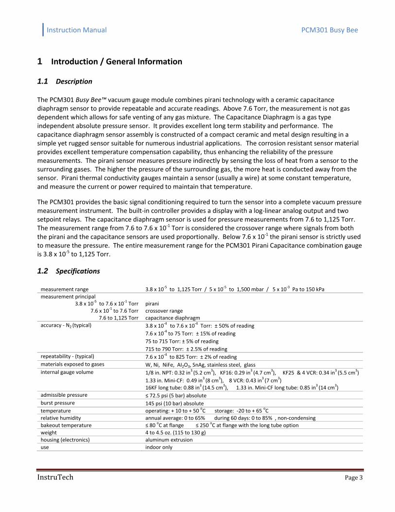
The PCM301 Busy Bee™ vacuum gauge module combines pirani technology with a ceramic capacitance diaphragm sensor to provide repeatable and accurate readings. Above 7.6 Torr, the measurement is not gas dependent which allows for safe venting of any gas mixture. The Capacitance Diaphragm is a gas type independent absolute pressure sensor. It provides excellent long term stability and performance. The capacitance diaphragm sensor assembly is constructed of a compact ceramic and metal design resulting in a simple yet rugged sensor suitable for numerous industrial applications. The corrosion resistant sensor material provides excellent temperature compensation capability, thus enhancing the reliability of the pressure measurements. The pirani sensor measures pressure indirectly by sensing the loss of heat from a sensor to the surrounding gases. The higher the pressure of the surrounding gas, the more heat is conducted away from the sensor. Pirani thermal conductivity gauges maintain a sensor (usually a wire) at some constant temperature, and measure the current or power required to maintain that temperature.
The PCM301 provides the basic signal conditioning required to turn the sensor into a complete vacuum pressure measurement instrument. The built-in controller provides a display with a log-linear analog output and two setpoint relays. The capacitance diaphragm sensor is used for pressure measurements from 7.6 to 1,125 Torr. The measurement range from 7.6 to 7.6 x 10⁻¹ Torr is considered the crossover range where signals from both the pirani and the capacitance sensors are used proportionally. Below 7.6 x 10⁻¹ the pirani sensor is strictly used to measure the pressure. The entire measurement range for the PCM301 Pirani Capacitance combination gauge is 3.8 x 10⁻⁵ to 1,125 Torr.
1.2 Specifications
measurement range 3.8 x 10⁻⁵
to 1,125 Torr / 5 x 10⁻⁵
to 1,500 mbar / 5 x 10⁻³
Pa to 150 kPa
measurement principal 3.8 x 10
-5 to 7.6 x 10
-1 Torr
7.6 x 10⁻¹
to 7.6 Torr 7.6 to 1,125 Torr
pirani crossover range capacitance diaphragm
accuracy - N2 (typical) 3.8 x 10⁻⁴
to 7.6 x 10⁻⁴
Torr: ± 50% of reading
7.6 x 10⁻⁴
to 75 Torr: ± 15% of reading
75 to 715 Torr: ± 5% of reading
715 to 790 Torr: ± 2.5% of reading repeatability - (typical) 7.6 x 10
-4 to 825 Torr: ± 2% of reading
materials exposed to gases W, Ni, NiFe, AI2O3, SnAg, stainless steel, glass
internal gauge volume 1/8 in. NPT: 0.32 in3
(5.2 cm3), KF16: 0.29 in
3 (4.7 cm
3), KF25 & 4 VCR: 0.34 in
3 (5.5 cm
3)
1.33 in. Mini-CF: 0.49 in3
(8 cm3), 8 VCR: 0.43 in
3 (7 cm
3)
16KF long tube: 0.88 in3
(14.5 cm3), 1.33 in. Mini-CF long tube: 0.85 in
3 (14 cm
3)
admissible pressure ≤ 72.5 psi (5 bar) absolute
burst pressure 145 psi (10 bar) absolute
temperature operating: + 10 to + 50 oC storage: -20 to + 65
oC
relative humidity annual average: 0 to 65% during 60 days: 0 to 85% , non-condensing
bakeout temperature ≤ 80 oC at flange ≤ 250
oC at flange with the long tube option
weight 4 to 4.5 oz. (115 to 130 g) housing (electronics) aluminum extrusion
use indoor only
Instruction Manual PCM301 Busy Bee
InstruTech Page 4
mounting orientation any
analog output log-linear 0 to 8 Vdc, 1 V/decade output impedance 2 × 4.7 , short-circuit proof
load impedance ≥10 k, short-circuit proof
error signal analog output switches to 0 V response time < 30 ms
input power (1)
15 to 30 Vdc, ≤ 2.5 W protected against power reversal fuse required 1 AT
supply voltage ripple <1 p-p
setpoint relays 2 Solid State, normally open, potential free, <30 V (ac) / (dc), ≤0.3 A resistive setpoint relay hysteresis
(2) 10% of threshold
setpoint relay range (N2) 3.8 x 10⁻⁵
to 1,125 Torr
setpoint switching time <30 msec connector 9-pin D-sub male
diagnostics port 3-pin, 2.5 mm Jack connector
CE compliance EMC (EN61000-6-2, EN61000-6-3, EN61010)
environmental RoHS compliant
(1) WARNING! The gauge may only be connected to power supplies, instruments, or control devices that conform to the
requirements of a grounded protective extra-low voltage (SELV) and limited power source (LPS), Class 2. The connection to the gauge has to be fused.
(2) The hysteresis and the switching characteristics can be programmed via the diagnostic port.
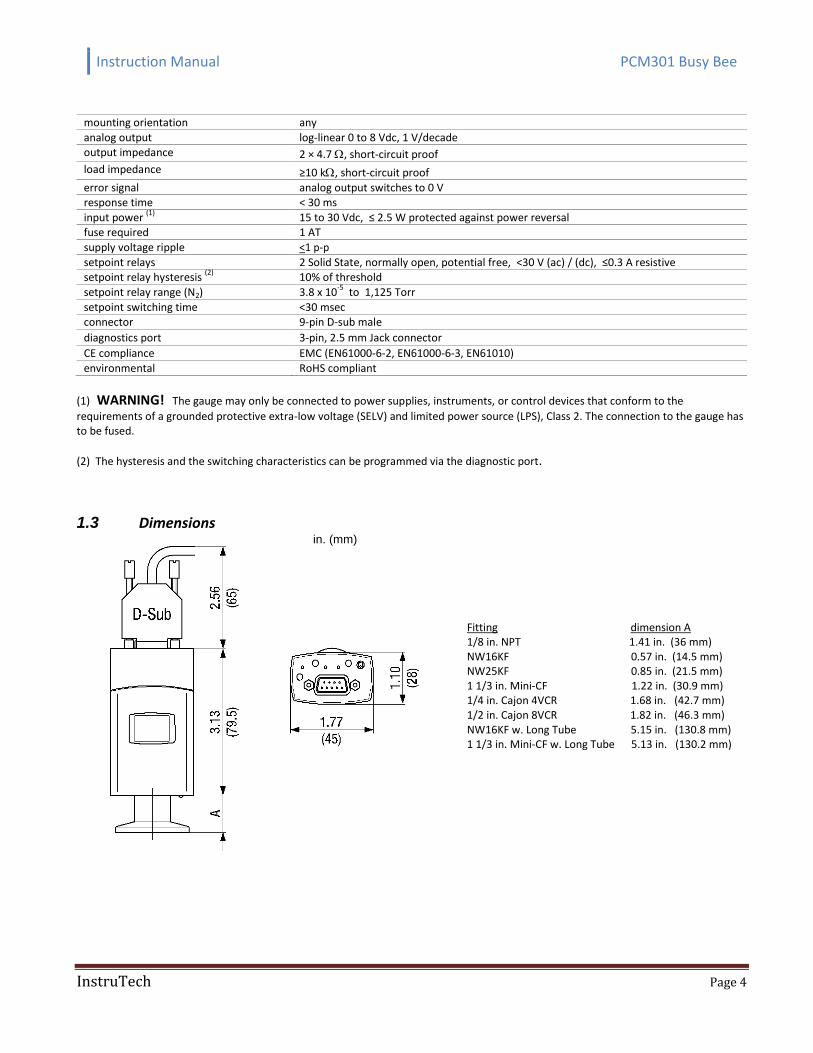
1.3 Dimensions in. (mm)
Fitting dimension A 1/8 in. NPT 1.41 in. (36 mm) NW16KF 0.57 in. (14.5 mm) NW25KF 0.85 in. (21.5 mm) 1 1/3 in. Mini-CF 1.22 in. (30.9 mm) 1/4 in. Cajon 4VCR 1.68 in. (42.7 mm) 1/2 in. Cajon 8VCR 1.82 in. (46.3 mm) NW16KF w. Long Tube 5.15 in. (130.8 mm) 1 1/3 in. Mini-CF w. Long Tube 5.13 in. (130.2 mm)
Instruction Manual PCM301 Busy Bee
InstruTech Page 5
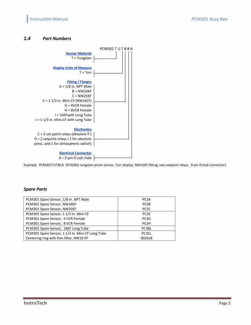
1.4 Part Numbers
Sensor Material
T = Tungsten
PCM301 T U T # # A
Display Units of Measure
T = Torr
Fitting / Flanges
A = 1/8 in. NPT Male
B = NW16KF C = NW25KF
E = 1 1/3 in. Mini-CF (NW16CF) G = 4VCR Female H = 8VCR Female
I = 16KFwith Long Tube J = 1 1/3 in. Mini-CF with Long Tube
Electronics
C = 2 set-point relays (absolute P.) D = 2 setpoint relays ( 1 for absolute press. and 1 for atmospheric switch)
Electrical Connector A = 9-pin D-sub male
Example: PCM301TUTBCA (PCM301 tungsten pirani sensor, Torr display, NW16KF fitting, two setpoint relays, 9-pin D-Sub Connector)
Spare Parts
PCM301 Spare Sensor, 1/8 in. NPT Male PCM301 Spare Sensor, NW16KF PCM301 Spare Sensor, NW25KF
PC3A PC3B PC3C
PCM301 Spare Sensor, 1 1/3 in. Mini-CF PCM301 Spare Sensor, 4 VCR Female PCM301 Spare Sensor, 8 VCR Female
PC3E PC3G PC3H
PCM301 Spare Sensor, 16KF Long Tube PC3BL
PCM301 Spare Sensor, 1 1/3 in. Mini-CF Long Tube Centering ring with fine filter, NW16 KF
PC3EL 002628
Instruction Manual PCM301 Busy Bee
InstruTech Page 6
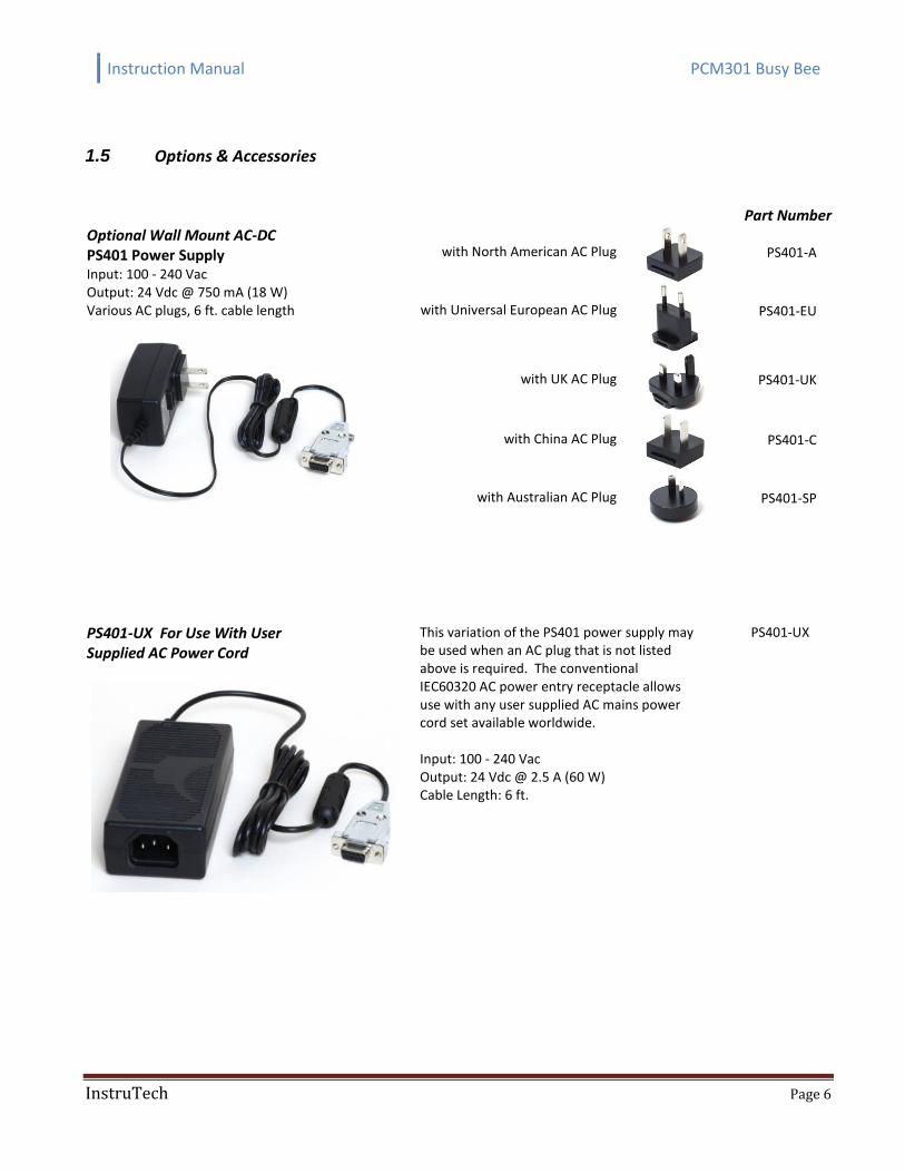
1.5 Options & Accessories
Part Number Optional Wall Mount AC-DC PS401 Power Supply Input: 100 - 240 Vac Output: 24 Vdc @ 750 mA (18 W) Various AC plugs, 6 ft. cable length
with North American AC Plug
PS401-A
with Universal European AC Plug
PS401-EU
with UK AC Plug
PS401-UK
with China AC Plug
PS401-C
with Australian AC Plug
PS401-SP
PS401-UX For Use With User Supplied AC Power Cord
This variation of the PS401 power supply may be used when an AC plug that is not listed above is required. The conventional IEC60320 AC power entry receptacle allows use with any user supplied AC mains power cord set available worldwide. Input: 100 - 240 Vac Output: 24 Vdc @ 2.5 A (60 W) Cable Length: 6 ft.
PS401-UX
Instruction Manual PCM301 Busy Bee
InstruTech Page 7
2 Important Safety Information
InstruTech has designed and tested this product to provide safe and reliable service, provided it is installed and operated within the strict safety guidelines provided in this manual. Please read and follow all warnings and instructions.
To avoid serious injury or death, follow the safety information in this document. Failure to comply with these safety procedures could result in serious bodily harm, including death, and or property damage. Failure to comply with these warnings violates the safety standards of installation and intended use of this instrument. InstruTech disclaims all liability for the customer’s failure to comply with these instructions. Although every attempt has been made to consider most possible installations, InstruTech cannot anticipate every contingency that arises from various installations, operation, or maintenance of the module. If you have any questions about the safe installation and use of this product, please contact InstruTech.
2.1 Safety Precautions - General
The product should never be operated with the electronics cover removed.
WARNING! Do not modify this product or substitute any parts without authorization of qualified InstruTech service trained personnel. Return the product to an InstruTech qualified service and repair center to ensure that all safety features are maintained. Do not use this product if unauthorized modifications have been made.
WARNING! Source power must be removed from the product prior to performing any servicing.
WARNING! The gauge may only be connected to power supplies, instruments, or control devices that conform to the requirements of a grounded protective extra-low voltage (SELV) and limited power source (LPS), Class 2. The connection to the gauge has to be fused. After servicing this product, ensure that all safety checks are made by a qualified service person. When replacement parts are required, ensure that the parts are specified by InstruTech. Substitutions of non-qualified parts may result in fire, electric shock or other hazards. Use of unauthorized parts or modifications made to this product will void the warranty. To reduce the risk of fire or electric shock, do not expose this product to rain or moisture. These products are not waterproof and careful attention must be paid to not spill any type of liquid onto these products. Do not use these products if they have been damaged. Immediately contact InstruTech to arrange return of the product if it is damaged.
WARNING
WARNING WARNING
Instruction Manual PCM301 Busy Bee
InstruTech Page 8
Due to the possibility of corrosion when used in certain environmental conditions, it is possible that the product’s safety could be compromised over time. It is important that the product be periodically inspected for sound electrical connections and equipment grounding. Do not use if the equipment grounding or electrical insulation has been compromised.
2.2 Safety Precautions - Service and operation
Ensure that the vacuum port on which the PCM301 is mounted is electrically grounded. Use an appropriate power source of 15 to 30 Vdc, 2.5 W minimum. Turn off power to the unit before attempting to service the module. Turn off power to the unit before detaching the electronics from the sensor for sensor replacement, sensor cleaning or bakeout purposes. Turn off power to the unit if a cable or plug is damaged or the product is not operating normally according to this instruction manual. Contact qualified InstruTech service personnel for any service or troubleshooting condition that may not be covered by this instruction manual. Do not use if the unit has been dropped or the enclosure has been damaged. Contact InstruTech for return authorization and instructions for returning the product to InstruTech for evaluation. Gauge failures due to contamination or wear and tear are not covered by the warranty. We recommend checking the zero at regular intervals.
2.3 Electrical Conditions
WARNING! When high voltage is present in any vacuum system, a life threatening electrical shock hazard may exist unless all exposed electrical conductors are maintained at earth ground potential. This applies to all products that come in contact with the gas contained in vacuum chambers. An electrical discharge within a gaseous environment may couple dangerous high voltage directly to any ungrounded conductor of electricity. A person could be seriously injured or killed by coming in contact with an exposed, ungrounded electrical conductor at high voltage potential. This condition applies to all products that may come in contact with the gas inside the vacuum chamber (vacuum/pressure containment vessel).
2.3.1 Proper Equipment Grounding
WARNING! Hazardous voltages that could seriously injure or cause death are present in many vacuum processes. Verify that the vacuum connection port on which the gauge is mounted is electrically grounded. Consult a qualified Electrician if you are in doubt about your equipment grounding. Proper grounding of your equipment is essential for safety as well as intended operation of the equipment.
Instruction Manual PCM301 Busy Bee
InstruTech Page 9
The PCM301 must be electrically connected to the grounded vacuum chamber. The connection must conform to the requirements of a protective connection according to EN 61010: VCR® connections fulfill this requirement. For gauges with a KF connection, use a conductive metallic clamping ring.
WARNING! In order to protect personnel from electric shock and bodily harm, shield all conductors which are subject to potential high voltage electrical discharges in or around the vacuum system.
2.3.2 Electrical Interface and Control
It is the user’s responsibility to ensure that the electrical signals from this product and any connections made to external devices, for example, relays and solenoids, are used in a safe manner. Always double check the system set-up before using any signals to automate your process. Perform a hazardous operation analysis of your system design and ensure safeguards and personnel safety measures are taken to prevent injury and property damage.
2.4 Overpressure and use with hazardous gases
WARNING! Install suitable protective devices that will limit the level of pressure inside your vacuum chamber to less than what the vacuum chamber system components are capable of withstanding. For example, a quick-connect, O-ring compression fitting may forcibly release a mounted device from the vacuum chamber fitting with only a few psi over local uncorrected barometric (atmospheric) pressure. In cases where an equipment failure could cause a hazardous condition, always implement fail-safe system operation. For example, use a pressure relief device in an automatic backfill operation where a malfunction could result in high internal pressures if the pressure relief device was not installed on the chamber.
WARNING! Overpressure in the vacuum system > 14.5 psia (1 bar)
Injury caused by released parts and harm caused by escaping process gases can result if clamps are opened while the vacuum system is pressurized. Do not open any clamps while the vacuum system is pressurized. Use the type of clamps which are suited to overpressure.
WARNING! Overpressure in the vacuum system > 29 psia (2.5 bar)
KF connections with elastomer seals (O-rings) cannot withstand such pressures. Process media can thus leak and possibly damage your health. Use O-rings provided with an outer centering ring.
CAUTION! If the internal pressure of a vacuum measuring device is allowed to increase above local uncorrected barometric pressure (atmospheric pressure side), vacuum fittings may release and possible overpressure conditions may cause leaks that would allow the gas inside the tube to release into the atmosphere of the surrounding environment. Toxic, pyrophoric and flammable gases are examples of hazardous gases that if allowed to leak out of the vacuum/pressure containment vessel into the atmospheric
Instruction Manual PCM301 Busy Bee
InstruTech Page 10
environment, could cause bodily injury and possible damage to equipment. Never expose the vacuum measuring device internal volume to pressure above local atmospheric pressure when using hazardous gases.
2.5 Gas Dependency
WARNING! The measurement value is gas dependent below 7.6 Torr. The pressure reading applies to dry air, O2, CO and N2. For other gases, the measurements have to be corrected. Refer to section 5 titled “Using the gauge with different gases” for more details.
3 Installation
3.1 Mechanical Installation
WARNING! Fragile components. The ceramic sensor may be damaged by impacts. Do not drop the product and prevent shocks and impacts.
CAUTION! Dirt and damage can impair the function of the vacuum component. Take appropriate measures to ensure cleanliness and prevent damage. Touching the product or parts with bare hands increases the desorption rate. Always use clean, lint free gloves as well as clean tools when working with this product. Mount the gauge so that no vibrations occur. Should gauge adjustments become necessary in the future, be sure to install it so that the adjustment button can be accessed with a pin. Mount the PCM301 as close as possible to the pressure you want to measure. Long or restricted, small diameter tubing will create a pressure difference between your process chamber and the gauge. This may cause a delay in response to pressure changes. Mounting the PCM301 too close to a gas source inlet may also cause measurement and control instability. The PCM301 can be mounted in any orientation, however, if possible, mount the gauge with port down to help minimize the effect of any particles or condensation collecting in the gauge. For electrical safety purposes the housing of the gauge must be grounded to the vacuum chamber. When using KF flanges, metal clamps must be used to ensure proper grounding. Do not attempt to modify your flange in order to use non-metallic-type flange clamps. Be aware that some vacuum fittings such as NPT connections installed using Teflon tape may not allow for metal-to-metal contact between the vacuum gauge and the vacuum chamber. If such is the case, use a 12 gauge or larger copper wire to connect the vacuum gauge to a ground lug on your vacuum chamber. Use all metal vacuum fittings with metal seals when operating pressures are expected to be below 1.00 x 10⁻⁷ Torr (1.33 x 10⁻⁷ mbar, 1.33 x 10⁻⁵ Pa).
Instruction Manual PCM301 Busy Bee
InstruTech Page 11
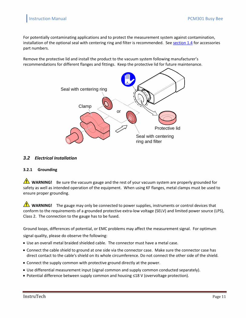
For potentially contaminating applications and to protect the measurement system against contamination, installation of the optional seal with centering ring and filter is recommended. See section 1.4 for accessories part numbers. Remove the protective lid and install the product to the vacuum system following manufacturer’s recommendations for different flanges and fittings. Keep the protective lid for future maintenance.
orClamp
Seal with centering ring
Seal with centeringring and filter
Protective lid
3.2 Electrical Installation
3.2.1 Grounding
WARNING! Be sure the vacuum gauge and the rest of your vacuum system are properly grounded for safety as well as intended operation of the equipment. When using KF flanges, metal clamps must be used to ensure proper grounding.
WARNING! The gauge may only be connected to power supplies, instruments or control devices that conform to the requirements of a grounded protective extra-low voltage (SELV) and limited power source (LPS), Class 2. The connection to the gauge has to be fused.
Ground loops, differences of potential, or EMC problems may affect the measurement signal. For optimum
signal quality, please do observe the following:
Use an overall metal braided shielded cable. The connector must have a metal case.
Connect the cable shield to ground at one side via the connector case. Make sure the connector case has direct contact to the cable's shield on its whole circumference. Do not connect the other side of the shield.
Connect the supply common with protective ground directly at the power.
Use differential measurement input (signal common and supply common conducted separately).
Potential difference between supply common and housing ≤18 V (overvoltage protection).
Instruction Manual PCM301 Busy Bee
InstruTech Page 12
3.2.2 Connector
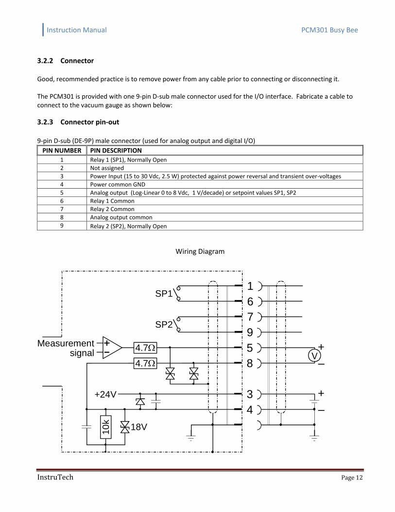
Good, recommended practice is to remove power from any cable prior to connecting or disconnecting it. The PCM301 is provided with one 9-pin D-sub male connector used for the I/O interface. Fabricate a cable to connect to the vacuum gauge as shown below:
3.2.3 Connector pin-out
9-pin D-sub (DE-9P) male connector (used for analog output and digital I/O)
PIN NUMBER PIN DESCRIPTION
1 Relay 1 (SP1), Normally Open
2 Not assigned
3 Power Input (15 to 30 Vdc, 2.5 W) protected against power reversal and transient over-voltages
4 Power common GND
5 Analog output (Log-Linear 0 to 8 Vdc, 1 V/decade) or setpoint values SP1, SP2
6 Relay 1 Common
7 Relay 2 Common
8 Analog output common
9 Relay 2 (SP2), Normally Open
Wiring Diagram
6
7
5
8
3
4
1
9
+
–
+
–
+24V
SP2
SP1
10
k
18V
4.7
4.7
Measurementsignal
Instruction Manual PCM301 Busy Bee
InstruTech Page 13
4 Setup and Operation
4.1 Gauge start up and operation
Read this user manual in its entirety before operating the instrument. The signal output is available when power is applied to the gauge. Allow for a stabilizing time of approx. 10 min. Once the gauge has been switched on, it can remain in operation continuously regardless of the pressure. Connect power to the PCM301 using the designated pins 3 and 4 of the 9-pin D-sub connector. Alternatively, you can power the device by connecting InstruTech’s PS401-A power supply to the gauge.
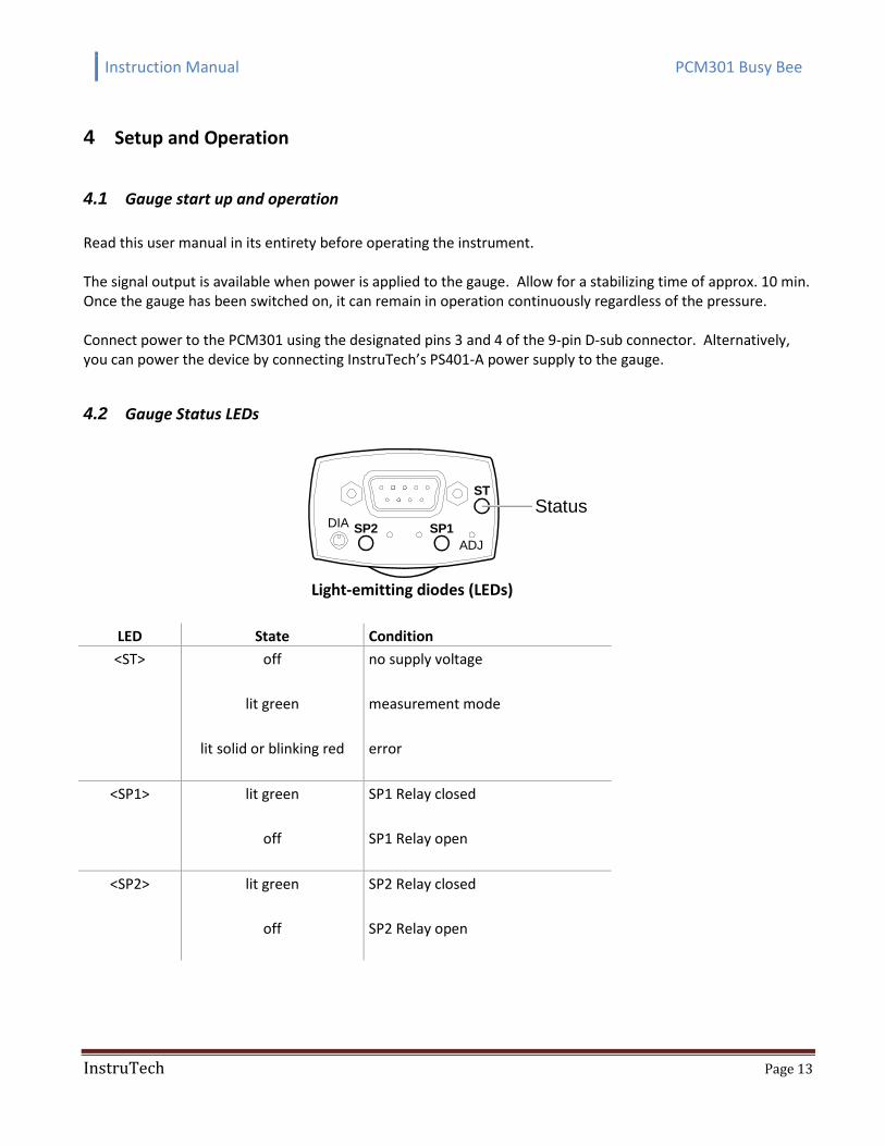
4.2 Gauge Status LEDs
SP1SP2
ADJ
ST
DIAStatus
Light-emitting diodes (LEDs)
LED State Condition
<ST> off
lit green
lit solid or blinking red
no supply voltage
measurement mode
error
<SP1> lit green
off
SP1 Relay closed
SP1 Relay open
<SP2> lit green
off
SP2 Relay closed
SP2 Relay open
Instruction Manual PCM301 Busy Bee
InstruTech Page 14
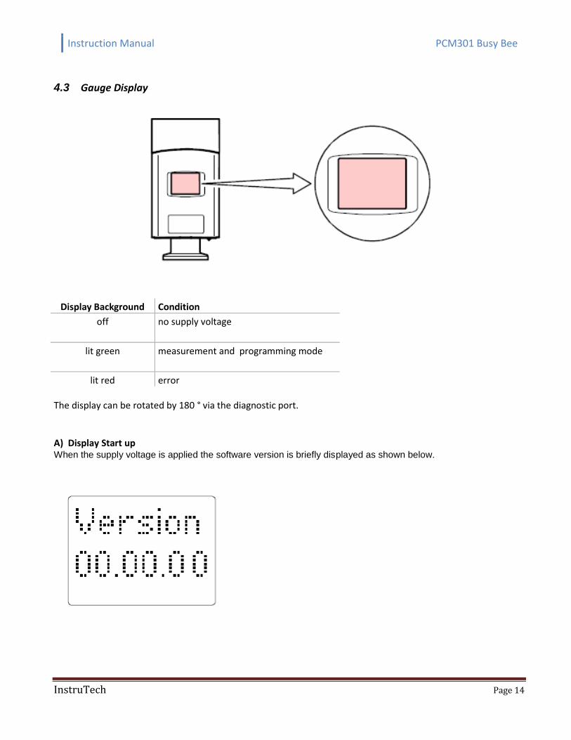
4.3 Gauge Display
Display Background Condition
off
no supply voltage
lit green measurement and programming mode
lit red error The display can be rotated by 180 ° via the diagnostic port. A) Display Start up When the supply voltage is applied the software version is briefly displayed as shown below.
Instruction Manual PCM301 Busy Bee
InstruTech Page 15
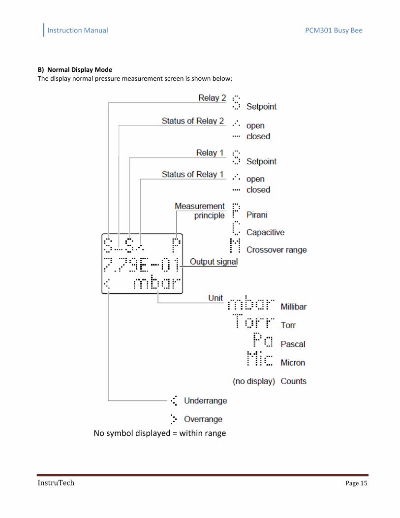
B) Normal Display Mode The display normal pressure measurement screen is shown below:
No symbol displayed = within range
Instruction Manual PCM301 Busy Bee
InstruTech Page 16
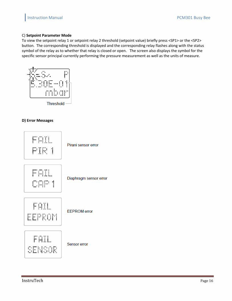
C) Setpoint Parameter Mode To view the setpoint relay 1 or setpoint relay 2 threshold (setpoint value) briefly press <SP1> or the <SP2> button. The corresponding threshold is displayed and the corresponding relay flashes along with the status symbol of the relay as to whether that relay is closed or open. The screen also displays the symbol for the specific sensor principal currently performing the pressure measurement as well as the units of measure.
D) Error Messages
Instruction Manual PCM301 Busy Bee
InstruTech Page 17
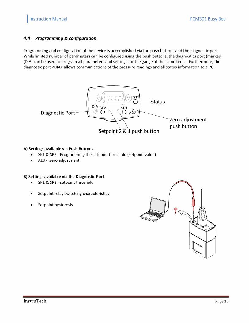
4.4 Programming & configuration
Programming and configuration of the device is accomplished via the push buttons and the diagnostic port. While limited number of parameters can be configured using the push buttons, the diagnostics port (marked (DIA) can be used to program all parameters and settings for the gauge at the same time. Furthermore, the diagnostic port <DIA> allows communications of the pressure readings and all status information to a PC.
Diagnostic Port
SP1SP2
ADJ
ST
DIAStatus
Setpoint 2 & 1 push button
Zero adjustment push button
A) Settings available via Push Buttons
SP1 & SP2 - Programming the setpoint threshold (setpoint value)
ADJ - Zero adjustment B) Settings available via the Diagnostic Port
SP1 & SP2 - setpoint threshold
Setpoint relay switching characteristics
Setpoint hysteresis
Instruction Manual PCM301 Busy Bee
InstruTech Page 18
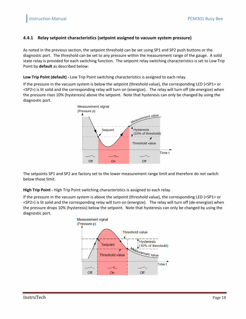
4.4.1 Relay setpoint characteristics (setpoint assigned to vacuum system pressure)
As noted in the previous section, the setpoint threshold can be set using SP1 and SP2 push buttons or the diagnostic port. The threshold can be set to any pressure within the measurement range of the gauge. A solid state relay is provided for each switching function. The setpoint relay switching characteristics is set to Low Trip Point by default as described below: Low Trip Point (default) - Low Trip Point switching characteristics is assigned to each relay.
If the pressure in the vacuum system is below the setpoint (threshold value), the corresponding LED (<SP1> or <SP2>) is lit solid and the corresponding relay will turn on (energize). The relay will turn off (de-energize) when the pressure rises 10% (hysteresis) above the setpoint. Note that hysteresis can only be changed by using the diagnostic port.
Time t
Measurement value
OffOn
Hysteresis(10% of threshold)
Off
Setpoint
Measurement signal
(Pressure p)
Threshold value
The setpoints SP1 and SP2 are factory set to the lower measurement range limit and therefore do not switch below those limit. High Trip Point - High Trip Point switching characteristics is assigned to each relay.
If the pressure in the vacuum system is above the setpoint (threshold value), the corresponding LED (<SP1> or <SP2>) is lit solid and the corresponding relay will turn on (energize). The relay will turn off (de-energize) when the pressure drops 10% (hysteresis) below the setpoint. Note that hysteresis can only be changed by using the diagnostic port.
Instruction Manual PCM301 Busy Bee
InstruTech Page 19
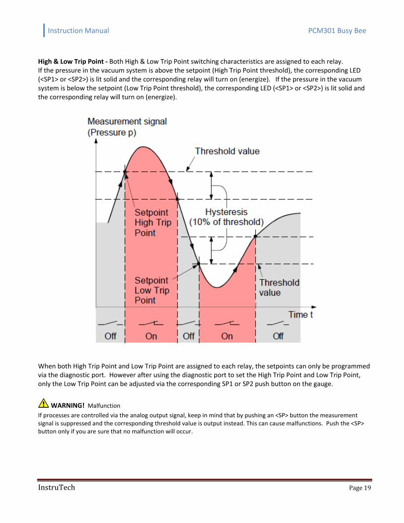
High & Low Trip Point - Both High & Low Trip Point switching characteristics are assigned to each relay. If the pressure in the vacuum system is above the setpoint (High Trip Point threshold), the corresponding LED (<SP1> or <SP2>) is lit solid and the corresponding relay will turn on (energize). If the pressure in the vacuum system is below the setpoint (Low Trip Point threshold), the corresponding LED (<SP1> or <SP2>) is lit solid and the corresponding relay will turn on (energize).
When both High Trip Point and Low Trip Point are assigned to each relay, the setpoints can only be programmed via the diagnostic port. However after using the diagnostic port to set the High Trip Point and Low Trip Point, only the Low Trip Point can be adjusted via the corresponding SP1 or SP2 push button on the gauge.
WARNING! Malfunction
If processes are controlled via the analog output signal, keep in mind that by pushing an <SP> button the measurement signal is suppressed and the corresponding threshold value is output instead. This can cause malfunctions. Push the <SP> button only if you are sure that no malfunction will occur.
Instruction Manual PCM301 Busy Bee
InstruTech Page 20
4.4.2 Programming the SP1 & SP2 setpoints with button on the gauge
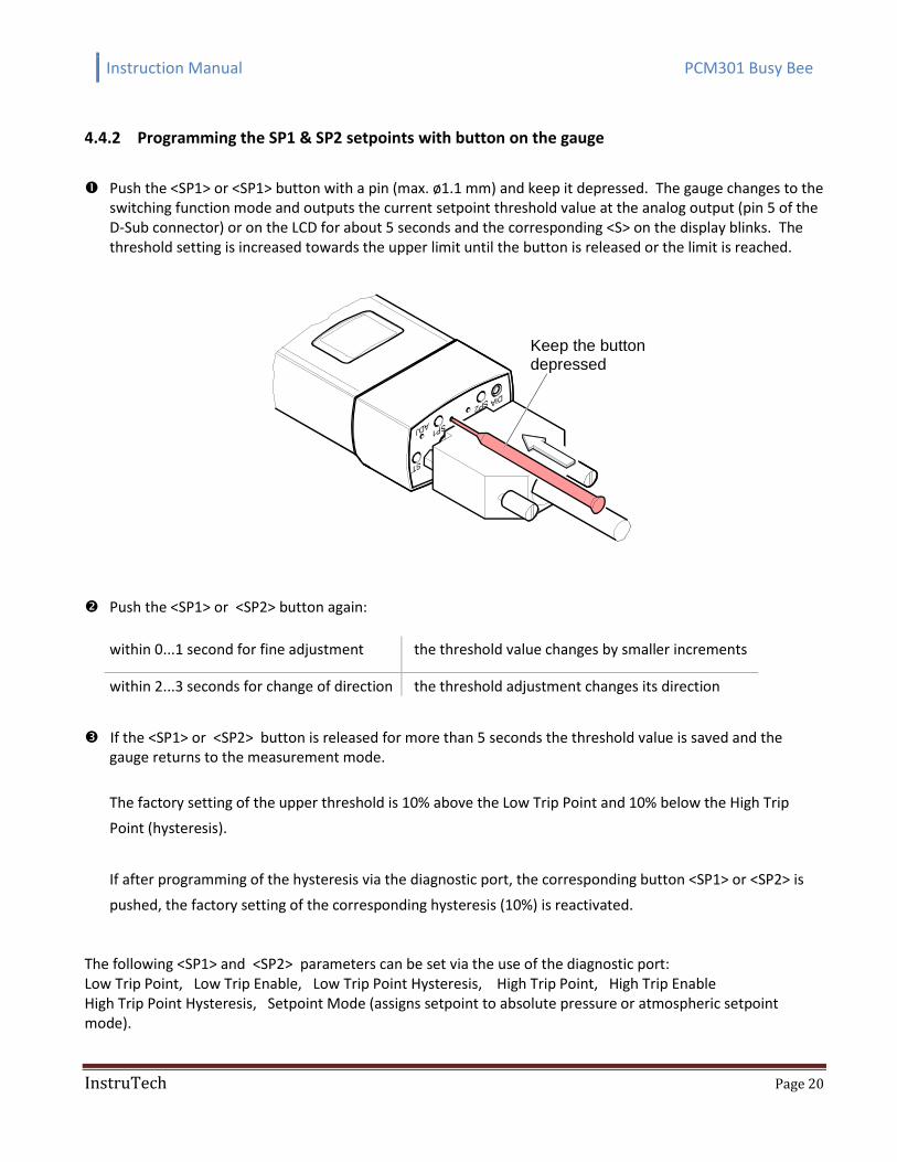
Push the <SP1> or <SP1> button with a pin (max. ø1.1 mm) and keep it depressed. The gauge changes to the switching function mode and outputs the current setpoint threshold value at the analog output (pin 5 of the D-Sub connector) or on the LCD for about 5 seconds and the corresponding <S> on the display blinks. The threshold setting is increased towards the upper limit until the button is released or the limit is reached.
Keep the buttondepressed
Push the <SP1> or <SP2> button again:
within 0...1 second for fine adjustment the threshold value changes by smaller increments
within 2...3 seconds for change of direction the threshold adjustment changes its direction
If the <SP1> or <SP2> button is released for more than 5 seconds the threshold value is saved and the gauge returns to the measurement mode.
The factory setting of the upper threshold is 10% above the Low Trip Point and 10% below the High Trip
Point (hysteresis).
If after programming of the hysteresis via the diagnostic port, the corresponding button <SP1> or <SP2> is
pushed, the factory setting of the corresponding hysteresis (10%) is reactivated. The following <SP1> and <SP2> parameters can be set via the use of the diagnostic port: Low Trip Point, Low Trip Enable, Low Trip Point Hysteresis, High Trip Point, High Trip Enable High Trip Point Hysteresis, Setpoint Mode (assigns setpoint to absolute pressure or atmospheric setpoint mode).
Instruction Manual PCM301 Busy Bee
InstruTech Page 21
4.4.3 Relay setpoint characteristics (atmospheric pressure (ATM) setpoint)
The setpoints <SP1> and <SP2> of gauges with separate atmospheric pressure sensor 1) can be programmed to atmospheric pressure setpoint (ATM setpoint) via the diagnostic port.
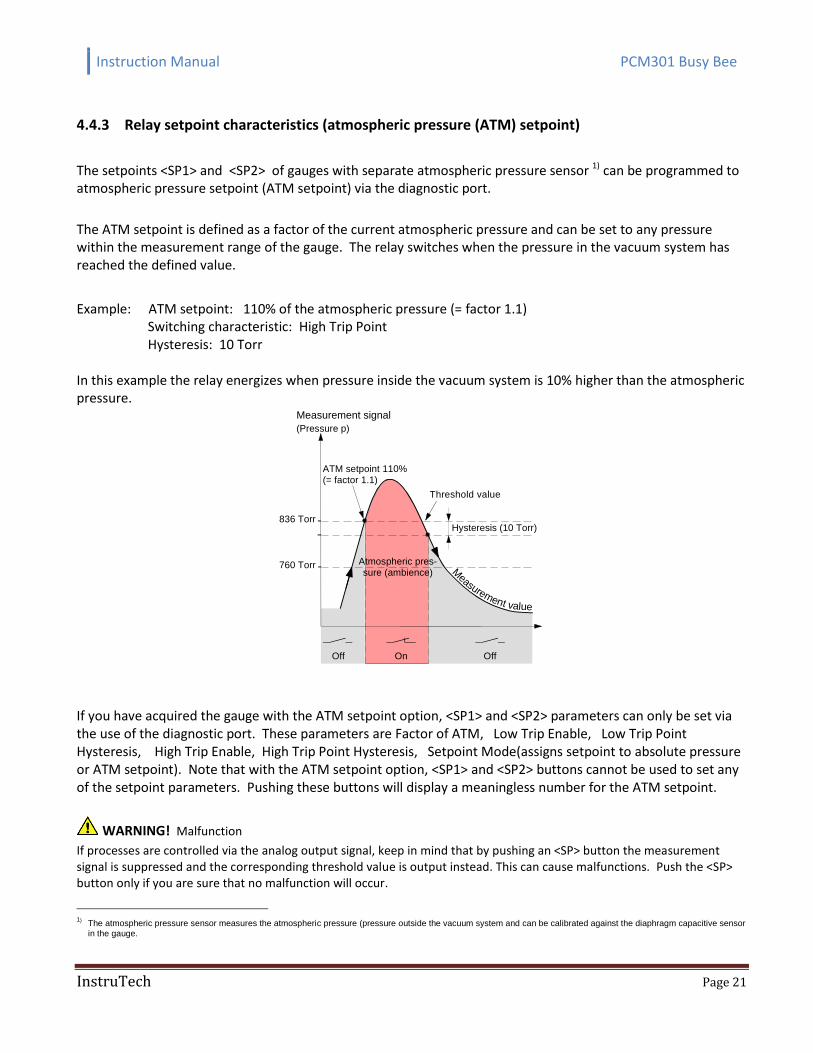
The ATM setpoint is defined as a factor of the current atmospheric pressure and can be set to any pressure within the measurement range of the gauge. The relay switches when the pressure in the vacuum system has reached the defined value.
Example: ATM setpoint: 110% of the atmospheric pressure (= factor 1.1) Switching characteristic: High Trip Point Hysteresis: 10 Torr
In this example the relay energizes when pressure inside the vacuum system is 10% higher than the atmospheric pressure.
836 Torr
760 Torr Atmospheric pres-sure (ambience)
ATM setpoint 110%(= factor 1.1)
Hysteresis (10 Torr)
OffOnOff
Measurement value
Measurement signal
(Pressure p)
Threshold value
If you have acquired the gauge with the ATM setpoint option, <SP1> and <SP2> parameters can only be set via the use of the diagnostic port. These parameters are Factor of ATM, Low Trip Enable, Low Trip Point Hysteresis, High Trip Enable, High Trip Point Hysteresis, Setpoint Mode(assigns setpoint to absolute pressure or ATM setpoint). Note that with the ATM setpoint option, <SP1> and <SP2> buttons cannot be used to set any of the setpoint parameters. Pushing these buttons will display a meaningless number for the ATM setpoint.
WARNING! Malfunction
If processes are controlled via the analog output signal, keep in mind that by pushing an <SP> button the measurement signal is suppressed and the corresponding threshold value is output instead. This can cause malfunctions. Push the <SP> button only if you are sure that no malfunction will occur.
1) The atmospheric pressure sensor measures the atmospheric pressure (pressure outside the vacuum system and can be calibrated against the diaphragm capacitive sensor
in the gauge.
Instruction Manual PCM301 Busy Bee
InstruTech Page 22
The operational characteristic curve of the gauge may change due to contamination and extended period of use. Periodically check the zero and adjust it if necessary.
4.4.4 Zero adjustment
For adjusting the zero, operate the gauge under the same constant ambient conditions and in the same normal mounting orientation.
If you are using a seal with centering ring and filter, check that they are clean or replace them if necessary.
Evacuate the vacuum system to a pressure less than 7.6 X 10⁻⁶ Torr and wait at least 2 minutes.
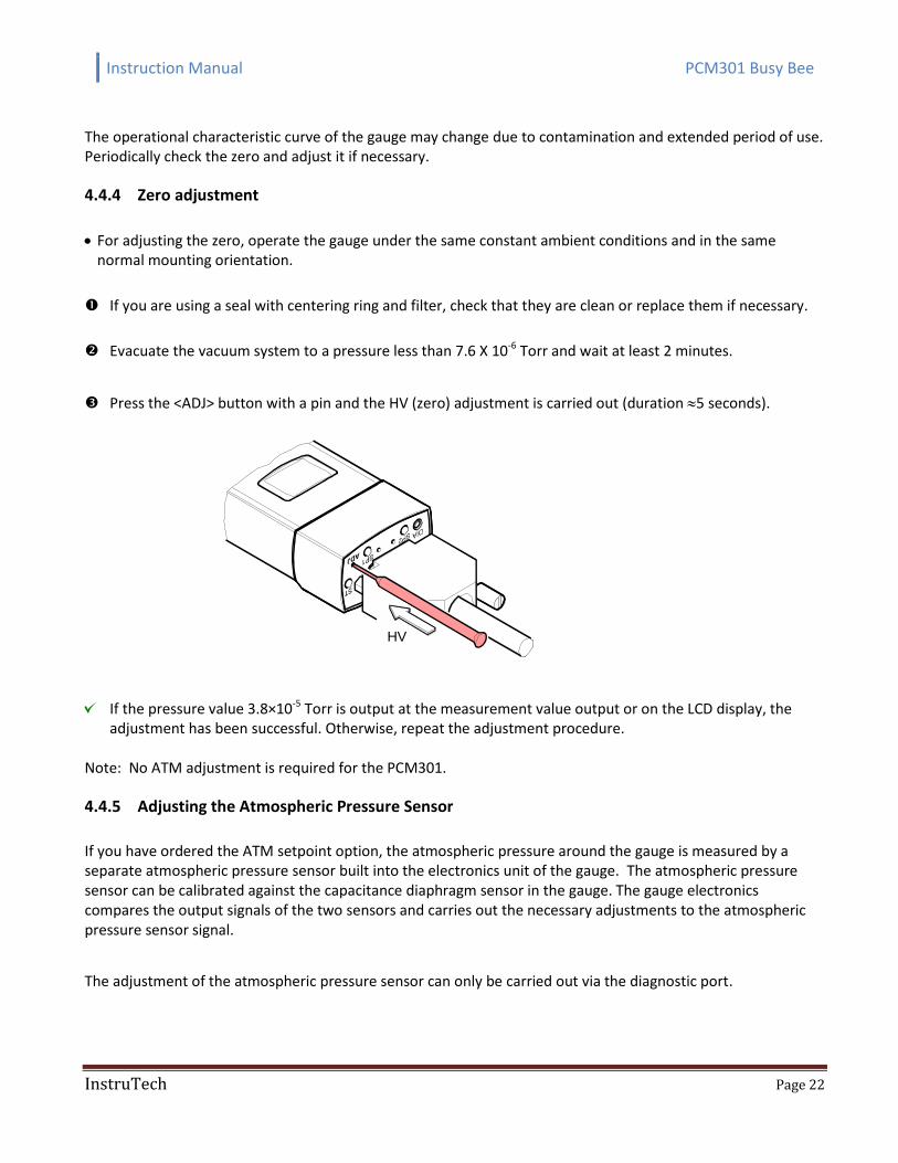
Press the <ADJ> button with a pin and the HV (zero) adjustment is carried out (duration 5 seconds).
HV
If the pressure value 3.8×10⁻⁵ Torr is output at the measurement value output or on the LCD display, the adjustment has been successful. Otherwise, repeat the adjustment procedure.
Note: No ATM adjustment is required for the PCM301.
4.4.5 Adjusting the Atmospheric Pressure Sensor
If you have ordered the ATM setpoint option, the atmospheric pressure around the gauge is measured by a separate atmospheric pressure sensor built into the electronics unit of the gauge. The atmospheric pressure sensor can be calibrated against the capacitance diaphragm sensor in the gauge. The gauge electronics compares the output signals of the two sensors and carries out the necessary adjustments to the atmospheric pressure sensor signal.
The adjustment of the atmospheric pressure sensor can only be carried out via the diagnostic port.
Instruction Manual PCM301 Busy Bee
InstruTech Page 23
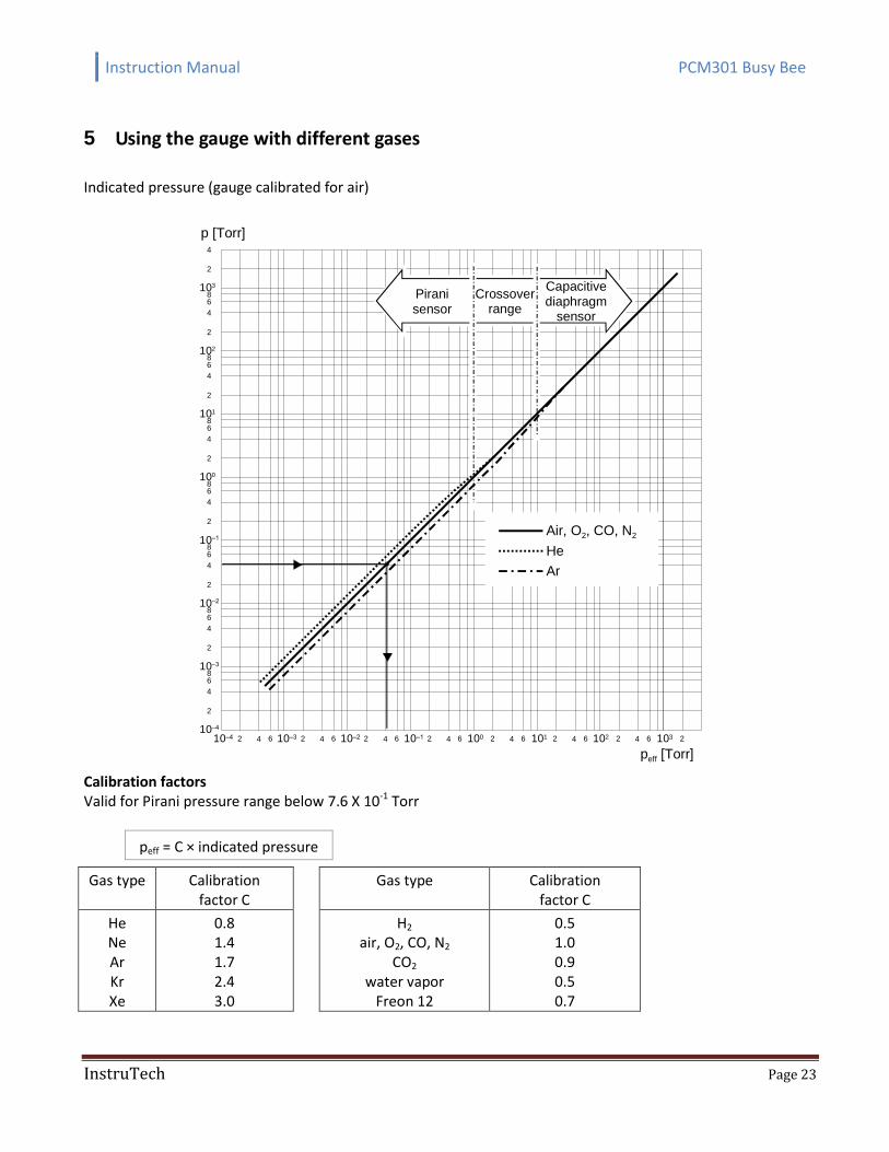
5 Using the gauge with different gases
Indicated pressure (gauge calibrated for air)
102
101
100
10–1
10–2
86
4
2
10–3
10–4 2 4 6 10–3 2 4 6 10–2 2 4 6 2 4 6 100 2 4 6 10110–110–4
peff [Torr]
2 4 6 102 2 4 6 103
103
p [Torr]
2
Air, O2, CO, N2
He
Ar
86
4
2
86
4
2
86
4
2
86
4
2
86
4
2
86
4
2
4
2
Capacitivediaphragm
sensor
Crossoverrange
Piranisensor
Calibration factors Valid for Pirani pressure range below 7.6 X 10⁻¹ Torr
peff = C × indicated pressure
Gas type Calibration factor C
Gas type Calibration factor C
He Ne Ar Kr Xe
0.8 1.4 1.7 2.4 3.0
H2 air, O2, CO, N2
CO2 water vapor
Freon 12
0.5 1.0 0.9 0.5 0.7

Instruction Manual PCM301 Busy Bee
InstruTech Page 24
6 Analog Output The PCM301 provides a 0 to 8 Vdc, 1 V/decade log-linear signal proportional to pressure.
Pressure (Torr) Analog Output (Vdc)
0.0001 1.000
0.0002 1.301
0.0005 1.699
0.0010 2.000
0.0020 2.301
0.0050 2.699
0.0100 3.000
0.0200 3.301
0.0500 3.699
0.1000 4.000
0.2000 4.301
0.5000 4.699
1.0000 5.000
2.0000 5.301
5.0000 5.699
10.0000 6.000
20.0000 6.301
50.0000 6.699
100.0000 7.000
200.0000 7.301
300.0000 7.477
400.0000 7.602
500.0000 7.699
600.0000 7.778
700.0000 7.845
760.0000 7.881
800.0000 7.903
900.0000 7.954
1000.0000 8.000
1,125.0000 8.051
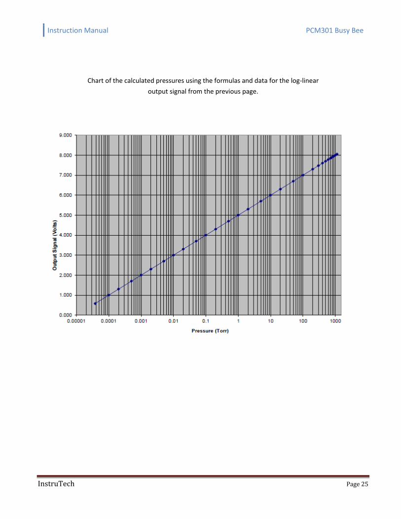
The log-linear output signal and pressure in the table above are related by the following formulas:
P = 10(V - 5) V = log10(P) + 5
where P is the pressure in Torr, and V is the output signal in volts.
An analog output of less than 0.01 volts to near 0 volt indicates a damaged or faulty sensor.
Instruction Manual PCM301 Busy Bee
InstruTech Page 25
Chart of the calculated pressures using the formulas and data for the log-linear
output signal from the previous page.
Instruction Manual PCM301 Busy Bee
InstruTech Page 26
7 Service
7.1 Calibration
The gauge is factory-calibrated and the pressure reading applies to dry air, O2, CO and N2. For other gases below 7.6 X 10⁻¹ Torr, the readings have to be corrected as described in section 5.
7.2 Maintenance
In general, under clean operating conditions, maintenance is not required for the PCM301. The operational characteristic curve of the gauge may change due to contamination and extended period of use. Periodically check the zero and adjust it if necessary (See section 4.4.4 for Zero Adjustment instructions).
In case of a defect the sensor can be replaced in the field.
InstruTech assumes no liability and the warranty becomes null and void if any repair work other than replacing the sensor is carried out by the end-user or third parties.
7.3 Contamination
The most common cause of all vacuum gauge failures is contamination of the sensor. Noisy or erratic readings, gauge failures due to contamination or wear and tear, as well as expendable parts (e.g. replacement sensor) are not covered by the warranty.
Contamination can to a certain extent be reduced by:
Geometric protection (e.g. screenings, elbows) against particles that spread rectilinearly
Mounting the flange of the gauge at a place where the partial pressure of the pollutants is particularly low.
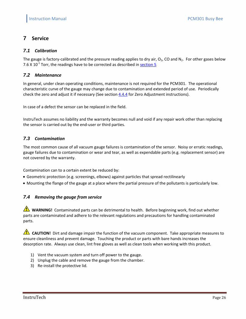
7.4 Removing the gauge from service
WARNING! Contaminated parts can be detrimental to health. Before beginning work, find out whether parts are contaminated and adhere to the relevant regulations and precautions for handling contaminated parts.
CAUTION! Dirt and damage impair the function of the vacuum component. Take appropriate measures to ensure cleanliness and prevent damage. Touching the product or parts with bare hands increases the desorption rate. Always use clean, lint free gloves as well as clean tools when working with this product.
1) Vent the vacuum system and turn off power to the gauge. 2) Unplug the cable and remove the gauge from the chamber. 3) Re-install the protective lid.
Instruction Manual PCM301 Busy Bee
InstruTech Page 27
Protective lid
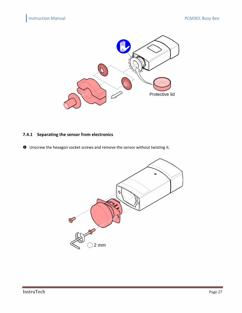
7.4.1 Separating the sensor from electronics
Unscrew the hexagon socket screws and remove the sensor without twisting it.
2 mm
Instruction Manual PCM301 Busy Bee
InstruTech Page 28
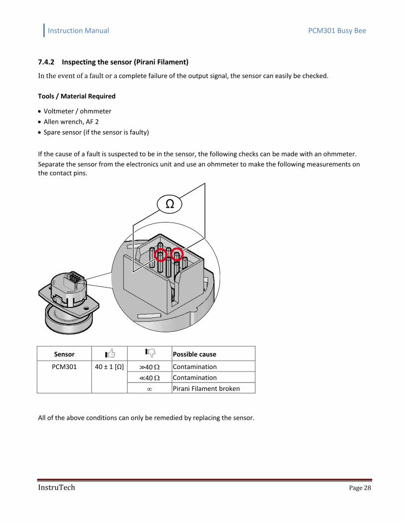
7.4.2 Inspecting the sensor (Pirani Filament)
In the event of a fault or a complete failure of the output signal, the sensor can easily be checked.
Tools / Material Required
Voltmeter / ohmmeter
Allen wrench, AF 2
Spare sensor (if the sensor is faulty)
If the cause of a fault is suspected to be in the sensor, the following checks can be made with an ohmmeter.
Separate the sensor from the electronics unit and use an ohmmeter to make the following measurements on the contact pins.
Ω
Sensor Possible cause
PCM301 40 ± 1 [Ω] >>40 Contamination
<<40 Contamination
Pirani Filament broken
All of the above conditions can only be remedied by replacing the sensor.
Instruction Manual PCM301 Busy Bee
InstruTech Page 29
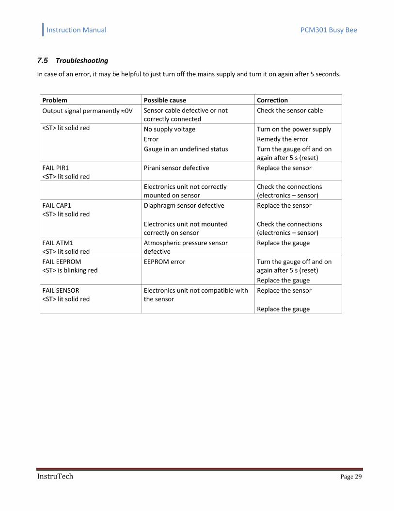
7.5 Troubleshooting
In case of an error, it may be helpful to just turn off the mains supply and turn it on again after 5 seconds.
Problem Possible cause Correction
Output signal permanently 0V Sensor cable defective or not correctly connected
Check the sensor cable
<ST> lit solid red No supply voltage Turn on the power supply
Error Remedy the error
Gauge in an undefined status Turn the gauge off and on again after 5 s (reset)
FAIL PIR1 <ST> lit solid red
Pirani sensor defective Replace the sensor
Electronics unit not correctly mounted on sensor
Check the connections (electronics – sensor)
FAIL CAP1 <ST> lit solid red
Diaphragm sensor defective Replace the sensor
Electronics unit not mounted correctly on sensor
Check the connections (electronics – sensor)
FAIL ATM1 <ST> lit solid red
Atmospheric pressure sensor defective
Replace the gauge
FAIL EEPROM <ST> is blinking red
EEPROM error Turn the gauge off and on again after 5 s (reset)
Replace the gauge
FAIL SENSOR <ST> lit solid red
Electronics unit not compatible with the sensor
Replace the sensor
Replace the gauge
Instruction Manual PCM301 Busy Bee
InstruTech Page 30
8 Factory Service and Support
If you need help setting up, operating, troubleshooting, or obtaining a return materials authorization number (RMA number) to return the module for diagnosis, please contact us during normal business hours (8:00am to 5:00pm Mountain time) Monday through Friday, at 303-651-0551. Or e-mail us at [email protected].
WARNING! Contaminated products (e.g. radioactive, toxic, caustic or microbiological hazard) can be detri-mental to health and environment. Products returned to InstruTech should be free of harmful substances. For the safety of our employees, you must download, complete and submit a material disclosure form from our website at www.instrutechinc.com Please use this form to provide a history of the product detailing what gases have been used. We cannot accept products that have been exposed to hazardous materials.
9 Warranty
SELLER warrants that its products are free of defects in workmanship and material and fit for the uses set forth in SELLER's catalog or product specifications, under the normal use and service for which they are intended. The entire warranty obligation of SELLER is for the repair or replacement, at SELLER's option, of products or parts (examination of which shall disclose to SELLER's satisfaction that it is defective) returned, to SELLER's plant, properly identified within twenty four (24) months (unless otherwise noted) after the date of shipment from InstruTech Plant. BUYER must obtain the approval of SELLER and a return authorization number prior to shipment. Alteration or removal of serial numbers or other identification marks renders this warranty void. The warranty does not apply to products or components which have been abused, altered, operated outside of the environmental specifications of the product, improperly handled or installed, or units which have not been operated in accordance with SELLER's instructions. Furthermore the warranty does not apply to products that have been contaminated (user assumes the responsibility in conjunction with the process media used), or when the product or part is damaged during the warranty period due to causes other than ordinary wear and tear to the product including, but not limited to, accidents, transportation, neglect, misuse, use of the product for any purpose other than that for which it was designed. THIS WARRANTY IS EXCLUSIVE AND IN LIEU OF ALL OTHER WARRANTIES, EXPRESS OR IMPLIED, INCLUDING ANY IMPLIED WARRANTY OF MERCHANTABILITY OR FITNESS FOR A PARTICULAR PURPOSE. THIS WARRANTY EXTENDS ONLY IN FAVOR OF THE ORIGINAL BUYER. THE BUYER'S SOLE REMEDY SHALL BE THE REPAIR OR REPLACEMENT, AS IS EXPRESSLY PROVIDED HEREIN, OF ANY WARRANTED DEFECTIVE PRODUCT OR PART, AND UNDER NO CIRCUMSTANCE SHALL SELLER BE LIABLE TO BUYER OR ANYONE ELSE FOR ANY CONSEQUENTIAL DAMAGES TO PERSONS OR PROPERTY, FOR INCIDENTAL DAMAGES OR LOSS OF TIME, FOR ANTICIPATED OR LOST PROFITS, OR ANY OTHER LOSS INCURRED BY THE BUYER RELATED TO THE PRODUCT COVERED BY THIS WARRANTY. THIS EXCLUSIVE REMEDY SHALL NOT BE DEEMED TO HAVE FAILED OF ITS ESSENTIAL PURPOSE SO LONG AS SELLER IS WILLING AND ABLE TO REPAIR OR REPLACE DEFECTIVE PARTS IN THE PRESCRIBED MANNER. THIS LIMITED WARRANTY MAY NOT BE MODIFIED BY SELLER UNLESS SUCH MODIFICATION OR WAIVER IS IN WRITING, EXECUTED BY AN AUTHORIZED OFFICER OF SELLER.

p/n 002663-100
InstruTech® 1475 S. Fordham St.
Longmont, CO 80503 USA
Phone +1-303-651-0551
Fax +1-303-678-1754 E-mail [email protected]
www.instrutechinc.com


![young auditorium Horizons Matinee Series · PDF fileA Busy Bee [Musical; Gr. K-5] ... premier children’s opera based on the book A Busy Bee: The Story of Bella the Honey Bee. ...](https://static.fdocuments.in/doc/165x107/5ab3b92c7f8b9a1d168ea307/young-auditorium-horizons-matinee-series-busy-bee-musical-gr-k-5-premier.jpg)


