Building 228 WEST AREA ME62 – ELECTRICAL SUBSTATION New HVAC system R. Bozzi / EN-CV.

The building level substation – the innovation of district heating system The building level substation (BLS) is suggested here as an innovation to the District Heating (DH) sector development in China. The BLS units are prefabricated compact products that are designed, manufactured and tested at the factory ready for transportation to the construction site, where the complete BLS unit will be mounted to the floor, connected to the existing indoor piping of heating and water, the remote communication facilities as well as to power supplies of the building. Domestic hot water (DHW) can also be integrated to DH. BLS makes it possible to complement the DH with DHW afterwards at low incremental costs: a small heat exchanger and a small circulation pump as well as connection to the existing DHW and city water piping are needed.
ISBN 978-951-38-8348-5 (Soft back ed.) ISBN 978-951-38-8349-2 (URL: http://www.vttresearch.com/impact/publications) ISSN-L 2242-1211 ISSN 2242-1211 (Print) ISSN 2242-122X (Online) http://urn.fi/URN:ISBN:978-951-38-8349-2
•VISIONS•S
CIE
NC
E•T
ECHNOLOGY•R
ES
EA
RC
HHIGHLIGHTS
231
The building level substation – the innovation of district heating system Kari Sipilä | Arto Nuorkivi | Jorma Pietiläinen

VTT TECHNOLOGY 231
The building level substation – the innovation of district heating system
Kari Sipilä & Jorma Pietiläinen
VTT Technical Research Centre of Finland Ltd
Arto Nuorkivi
Nuorkivi Consulting

ISBN 978-951-38-8348-5 (Soft back ed.) ISBN 978-951-38-8349-2 (URL: http://www.vttresearch.com/impact/publications)
VTT Technology 231
ISSN-L 2242-1211 ISSN 2242-1211 (Print) ISSN 2242-122X (Online) http://urn.fi/URN:ISBN:978-951-38-8349-2
Copyright © VTT 2015
JULKAISIJA – UTGIVARE – PUBLISHER
Teknologian tutkimuskeskus VTT Oy PL 1000 (Tekniikantie 4 A, Espoo) 02044 VTT Puh. 020 722 111, faksi 020 722 7001
Teknologiska forskningscentralen VTT Ab PB 1000 (Teknikvägen 4 A, Esbo) FI-02044 VTT Tfn +358 20 722 111, telefax +358 20 722 7001
VTT Technical Research Centre of Finland Ltd P.O. Box 1000 (Tekniikantie 4 A, Espoo) FI-02044 VTT, Finland Tel. +358 20 722 111, fax +358 20 722 7001
Cover image: Designed by Tuomo Hokkanen
Juvenes Print, Tampere 2015

3
PrefaceThe Manual comprises the aspects as outlined in the Table of Contents to follow.The Manual is based on the request of the Ministry of Housing, Urban and RuralDevelopment (MoHURD) on Dec. 2, 2014 to the Finnish VTT and Tekes delega-tion to support the national Heating Reform by providing guidance to building levelsubstation (BLS) implementation from institutional, economic and operational pointof view.
The authors of the Manual would like to extend their thanks to the commentsprovided by their excellencies, Messrs. Liu Heming and Han Aixing from Mo-HURD, Ass. Prof. Xia from Tsinghua University, Dr.Zhou Zhigang and Dr.WangPeng from Harbin Institute of Technology and by the task team leaders of districtheating projects, Messrs. Yanqin Song and Gailius G. Draugelis as well as thetechnical expert Dianjun Zhang from the World Bank Group.
The Manual at hand is produced by VTT Technical Research Centre of FinlandLtd, by Mr. Kari Sipilä in association with Dr. A. Nuorkivi under the sponsorship ofthe Finnish Energy Industries association, the Beautiful Beijing program of Finpro,City of Turku as well the individual companies such as Alfa Laval Nordic, Enoro,Högfors Valves, Kolmeks and Vexve.
The attachment of the Manual offers a comparison of the practice in DH be-tween China and Finland.
4
ContentsPreface ................................................................................................................. 3
List of symbols ..................................................................................................... 6
1. Concept of BLS .............................................................................................. 7
1.1 What is BLS?............................................................................................ 71.2 Heating Products of BLS ........................................................................... 81.3 Physical Dimensions of BLS...................................................................... 91.4 BLS supports Heating Reform ................................................................. 101.5 Manufacturing BLS ................................................................................. 11
2. Global Trends with Substations ................................................................... 12
2.1 BLS Worldwide ....................................................................................... 122.2 BLS in Finland ........................................................................................ 132.3 Customer Connection Procedure in Finland ............................................. 16
3. Expected Benefits of BLS Compared to GS ................................................ 18
3.1 General Benefits ..................................................................................... 183.2 Reduced Pumping .................................................................................. 193.3 Optimal Underground Piping ................................................................... 203.4 Improved Energy Efficiency ..................................................................... 21
4. Ownership and Cost Sharing ....................................................................... 22
4.1 Property Borders .................................................................................... 224.2 Ownership of BLS ................................................................................... 224.3 Cost Sharing .......................................................................................... 23
5. Institutional Barriers to be Addressed ......................................................... 24
5.1 Slow Commissioning of BLS ................................................................... 245.2 No Competition at Present ...................................................................... 245.3 Different Interest of DH Company and Developer ..................................... 255.4 Lump-sum Tariff ..................................................................................... 25
6. Technical Issues .......................................................................................... 26
6.1 Make-up Water ....................................................................................... 26
5
6.2 Expansion Compensation ....................................................................... 266.3 One- or Two Way Control........................................................................ 276.4 Heat Exchanger Design .......................................................................... 276.5 Heat Meter Reading Combined with Remote Controlling .......................... 286.6 Automation ............................................................................................. 306.7 IT Tools for Optimization ......................................................................... 336.8 Noise ..................................................................................................... 346.9 Safety..................................................................................................... 35
Annex 1: Sino-Fin Comparison of DH ............................................................... 36
Annex 2: Substation for connecting the building to heating networks ............ 38
Abstract

6
List of symbolsAbbreviation In English In Chinese
BLS Building level substationCHP Combined heat and power
plantDH District heatingDHW Domestic hot waterEU European UnionGS Group substationHoB Heat only boiler plantSCADA System for Computerized
Automation and Data Acquisi-tion
SH Space heating

7
1. Concept of BLS
1.1 What is BLS?
The building level substation (BLS) is suggested here as an innovation to the DHsector development in China. But what is BLS and what would it change? Introduc-tion of the BLS would provide obvious benefits in improved energy efficiency andliving comfort, but it also faces institutional barriers to overcome. In the following,the CHP concept will be described, and the economic, institutional and technicalissues associated to BLS will be addressed.
Figure 1. Building level substations (BLS) with capacity of about 10 000 m2
each in the factory ready for shipment to Chengde, Hebei Province, China.
In Fig. 1 a number of BLS units wait for the delivery to China. The BLS units wereinstalled in the city of Chengde, under co-financing of the grant from the GlobalEnvironmental Facility administrated by the World Bank.
The Figure below illustrates the difference in the substation culture between Chinaand Finland. In China, the substation serves 20–30 buildings through the secondary

8
underground network, whereas in Finland, the primary network extends to the build-ing basement where the BLS is connected to the indoor piping.
Figure 2. The network structures of the traditional group substation (GS) inChina and the building level substation (BLS) in Finland.
Typically, the BLS capacity is below 15 000 m2 of heated area equal up to 1 MW.The BLS units are prefabricated compact products that are designed, manufacturedand tested at the factory ready for transportation to the construction site, where thecomplete BLS unit will be mounted to the floor, connected to the existing indoorpiping of heating and water, the remote communication facilities as well as to powersupplies of the building.
The BLS as an integrated plate heat exchange unit shall be prefabricated and as-sembled and successfully tested both hydraulically and electrically in the factoryalready to meet the high functional and low noise requirements, and if he so wishes,at the presence of the Borrower’s representative. Its base and brazed structuresshould have sufficient intensity and stability.
1.2 Heating Products of BLS
Traditionally, only room space heating is used in Chinese DH. In other world, alsodomestic hot water is often integrated to DH. Introduction of BLS makes it possibleto complement the DH with DHW afterwards at low incremental costs: a small heatexchanger and a small circulation pump as well as connection to the existing DHWand city water piping are needed.

9
1.3 Physical Dimensions of BLS
The substations require room space depending on the size. Below a few examplesare given about the substations of various capacities.
Table 1. Examples of physical sizes of real substations.
The maximum physical dimensions of the BLS is given below in order to make itfeasible to transfer the BLS to the final operation site, and to use as little roomspace as possible but to be easy to maintain anyway.
Table 2. Physical dimensions of BLS to design the room space needed in thebuilding (mm).
Capacity Length Breadth Height
200 kW 1500 700 1600
400 kW 1700 750 1650
600 kW 1800 800 1700
800 kW 1900 850 1800
1000 kW 2000 900 1800
1200 kW 2200 950 1900
The room size of the BLS should be large enough to leave at least 1 m on eachside of the substation space free to walk and work.
The main components of the BLS are:
SUBSTATION DIMENSIONS Floor arealenght x width x height substation
mm m2WEIHAI 0,2 MW 1500x600x1600 0,9ULAN BATAR 0,4MW 2000x1000x1600 2,0HARBIN 1MW 2500x2000x2300 5,0BAOTOU 7MW 3000x4000x2300 12,0YANJI 9 MW 6500x4000x2400 26,0YANJI 13 MW 6000x3800x2300 22,8QINHUANGDAO 14MW 7000x4000x2300 28,0YANJI 17MW 6600x3900x2300 25,7

10
Plate heat exchangers, the number depending on the types ofheat consumptions such as space heating, DHW and ventila-tion.
Heat meter
A safety valve is in the secondary side to protect against highpressures.
The circulation pump with control system
A water flow sensor in the make-up water supply
Temperature control components together with communication
Circulation pump with frequency converter
Pump box
Shut-off valves
Strainers
As the BLS product will be transferred as one integral unit from the factory to thefinal operation site without any disassembling/reassembling in between, there is norisk of noise or excess consumption of electricity, heat and room space, but theoperation will be silent and optimal in the building.
The BLS can be carried through the normal doors of some 2.1 m high and 0.9 mbreadth to the final operation site in the building.
There is no international standard about the BLS for the time being but the“Guidelines for District Heating Substations” issued by Euroheat&Power, e.g. theDH association in Europe, in October 2008. The guidelines are downloadable fromthe link: http://euroheat.org/Technical-guidelines-28.aspx
1.4 BLS supports Heating Reform
To the Heating Sector Reform the BLS introduction offers essential advantagessuch as:
– Each building gets exactly the heat it needs.
– Heat control inside the rooms works better when the heat supply iscontrolled for the particular building in the BLS.
– A professional body, the DH company, will be responsible for the heatsupply quality until the building entrance, not only to the GS.
– Heat losses (inside and outside the building) can be allocated unam-biguously to either consumer or supplier. The building internal heatlosses are clearly the responsibility of the customer, e.g. the buildingowner.

11
– Heat metering can be organized at low cost on building level.
– Thus, heat tariffs can be clearly defined: covering the costs of supply-ing heat up to the substation, either before or behind the heat ex-changer of the BLS.
– Serial production is much more possible with BLS, thus providing lowerinvestment costs than with tailored GS units.
– BLS with primary network connection is flexible for expansion: everynew building will be equipped with a BLS whereas in a GS system anew building may either require capacity to be added to the GS or thesecondary networks or such excess capacity had to be reserved in thedesign phase already, both being costly.
– Low return temperature due to tuned functioning of the BLS accordingto the heating needs of the particular building will be achieved, whichimproves the overall economy of the DH/CHP system.
1.5 Manufacturing BLS
The BLS shall be manufactured and tested at the factory as one integral unit, whichthen will be transported to the final site to be connected to the building and DHinfrastructure.
At present, there are not many manufacturers of BLS in China, but as BLS be-coming more common based on the pilots financed by the World Bank, for instance,it is certain that the numerous heat exchanger manufactures currently operating inChina will add BLS to their product mix. This transition from imported to local manu-facturing has happened in many other imported products before already: plate heatexchangers, fluidized bed boilers, frequency control of pumps, etc. that used to beimported but which now are mainly of Chinese origin. The same will happen withBLS after the prevailing barriers have been phased out.

12
2. Global Trends with Substations
2.1 BLS Worldwide
The trend elsewhere in the world appears to either stay with BLS or to convert GStowards BLS as presented in the Table below.
Table 3. Countries with main practice on substations.
Common practice List of countriesCountries using GS Belarus, China, Denmark, Romania, Rus-
sia, UkraineCountries using BLS Austria, Bulgaria, Canada, Croatia, Czech
Republic, Estonia, Finland, France, Ger-many, Italy, Norway, Serbia , Sweden,Switzerland, United Kingdom, USA
Countries in transitionCountries moving from GS to BLS Poland, Hungary, Lithuania,
Countries moving from BLS to GS There are NONE.
A number of countries use BLS already, and some of the countries are turning fromGS to BLS. Nevertheless, none are moving other way round from BLS to GS.
In some cases, such as Russia and Denmark, for instance, not only group sub-stations and even direct connections are used but also BLS.
The heat exchangers of space heating can be either mountable, when openingand remounting of the heat exchanger plates is possible, or brazed, when the entireheat exchanger has to be replaced if broken or leaking. The latter brazed ones arereliable and much cheaper and smaller than the mountable ones, thus having hadgained market dominance in the world, as presented in Table below.

13
Table 4. Countries using mountable or brazed heat exchangers in SH circuits.
Heat exchanger type in spaceheating
Countries
Only mountable ChinaBrazed Austria, Bulgaria, Canada, Croatia, Czech Re-
public, Denmark, Estonia, Finland, France,Germany, Italy, Norway, Serbia, Sweden, Swit-zerland, United Kingdom, USA
Both brazed and mountable Belarus, Russia, Ukraine
2.2 BLS in Finland
DH in Finland has been awarded as the best DH system in the world with full fivestars by the IEA, the International Energy Agency, mainly because of high level ofintegration and energy efficiency. Moreover, the DH and district cooling systems ofHelsinki have been awarded as the best practice in the world by the IEA and theEuroheat & Power a number of times, for instance, Paris, France, 2009 and latest inNew York 2013.
In Finland, the customer is always the building owner, never the individual apart-ment. Each building has its own substation (BLS) separating the responsibility bor-der of the DH company and the building owner. The BLS is owned by the customer.
Apart from China, the BLS in Finland supplies heat both for SH and DHW. There-fore, there are always at least two heat exchangers and controllers in each substa-tion, sometimes the third one for air conditioning.
Finland is a small country with the population of only 5.5 million and the territory ofsome 300 000 km2, but located in the north with the highest heating requirementsprevailing in Europe. The outdoor temperature used as the design basis of the DHsystems ranges from -25°C in the south to -35°C in the north of Finland. Therefore,the heating systems have to be both reliable and adequate. The reliability of the DHsupplies to the customers amounts to as high as 99.98% of the calendar time, andthose less than 2 hours a year, the customer does not usually even recognize anybreak as the heat energy accumulated to the buildings and pipelines compensatesthe impacts. The Finnish Energy Industry Technology Association recommends thatthe back-up boiler capacity shall be sized to allow less than 10% lack of capacity inproduction for maximum 6 hours period at a time, when largest unit is out of opera-tion and winter peak demand exist. The network and booster pump stations must bedesigned that not any customer is allowed to stay totally out of heat more than 3hours. This recommendation takes into account the heat demand pattern and heatstorage characteristics of buildings and DH networks as well as separated heatstorages in some DH-systems.
Despite of northern location, the DH sales to customers, including both DHW andSH, amounted to 38 kWh/m3 of heated volume in year 2014 on average. The valuehas been constantly declining due to energy efficiency improvements in the existing

14
buildings and the new buildings being more or less passive or zero energy buildingsalready.
Moreover in Finland, DH has had to operate on the competitive market withoutmuch public support, which has made DH highly economic to be successful on theheating market. As competitors of DH during the past decades, oil and electric heat-ing and lately individual heat pumps have appeared. Today, the half of the popula-tion is with DH, about 75% of DH produced by highly efficient CHP and the fuel mixranging from fossil fuels to the constantly increasing share of renewable energysources.
Most DH companies in Finland are owned by the municipalities. There are twomain reasons to the municipal ownership such as (i) heating is local activity servingonly the local people, which makes the governmental involvement unnecessary,and (ii) DH together with CHP is a profitable business to the owner, even thoughboth electricity and heat function on open markets. As an example, the DH andCHP company of Helsinki, the capital of Finland, generated €250 million profit with€900 million turnover in year 2014. A good share of the profit was used by the cityas the owner to fund city development in favor of its citizens.
The DH industry by itself is not regulated in Finland, but the same customer rightprotection procedures apply to DH as to any other commercial product available onthe market such as food, electric appliances, house renting, etc. Because of DH isregionally in a dominant market position due to DH share of 90% and more of thelocal heat market, the Finnish Energy Market Authority follows the pricing of DHcompanies that the heat price is not over sized including a fair profit. Due to compe-tition on the market, the competitiveness and customer satisfaction, both constantlymonitored by the DH companies, are the driving forces of DH management in thewhole country.
The BLS is a rather standard product in Finland, but not officially standardized.The association Finnish Energy Industries1 issues recommendations to its membercompanies, both utilities and manufacturers, about required water quality, substa-tion structures, heat tariff systems, etc. The recommendations are not mandatory,but as the companies themselves have participated in preparing the recommenda-tions, the recommendations are implemented in practice. Therefore, the DH sys-tems in Finland both technically, institutionally and economically are rather uniformas designed, operated and maintained according to the mutually agreed recom-mendations. The association is based on voluntary membership of the energy com-panies in Finland. In practice, most DH companies are members of the FinnishEnergy Industries as they benefit from lobbying with the government, participation indevelopment work and information exchange.
The DH system is operated all year round because of continuous DHW supply,but SH is needed in the heating season only. All year round operation guaranteesalso better condition and reliability of DH systems compared to 3–4 months shut-down mode of the DH systems a year.
1 www.energia.fi

15
The connected buildings can switch on/off their heating individually as needed,because the DH system is in operation at all times.
An example of a Finnish DH system is given in the Fig. below. In the city of Hel-sinki, the capital of Finland, some 92% of the building stock is connected to the DH.About 90% of the DH energy is produced by the CHP plants Vuosaari, Salmisaariand Hanasaari and the balance of 8% by the large heat only boilers (HoB) spread inthe city area. The CHP energy is high as a base production even though the heatproduction capacities of CHP and the other sources are almost even, 1250 MWfrom CHP and 1350 MW from the HoBs and large heat pumps. The annual efficien-cy of the heat production is about 90% which is very high in the international con-text. The heat losses of the DH network are 6% of the annual heat production. Thewater losses of the DH systems are as low as some 0.08% of the circulation waterflow on average.
Figure 3. The various types of heat sources are interconnected to one integralring-type DH network in the city of Helsinki, Finland (2015). All 15 000 substa-
tion units are BLS.
VTT has developed in co-operation with Helen a Kopti software system to helpoptimally operate the energy production system in Helsinki. Fuel consumption,capacity operation, including energy storing and unit annual service break time areoptimized. Electricity trade in Nordic electricity trade market and local heat trade arealso included in the systems operation.
Helen has automated customer information system collecting electricity and heatconsumption data from remote read meters (ARM) at consumers, issues the cus-tomer electricity and heat bills according to the collected data. The data informationsystem gives also to customer his own measured consumption history informationin hourly/months level, if the customer wishes to have it.
RU Hob La HoB Ja HoB Pt HoB My HoBH: 240 MW H: 334 MW H: 50 MW H: 228 MW H: 70 MW
Al HoB Vuosaari AH: 132 MW 1 400 km network gas CHP
15 000 substations E: 160 MWSalmisaari 70 M m2 heating area H: 165 MWcoal andbiomass Sa HoB My HoB Vu HoB Vuosaari B
CHP H: 120 MW H: 240 MW H:120 MW gas CHPE: 160 MW E: 485 MWH: 480 MW Hanasaari Ha HoB H: 410 MW
coal and biomass CHP H: 235 MWMu HoB E: 230 MW Heat pumps
H: 235 MW H: 420 MW H: 90 MW

16
2.3 Customer Connection Procedure in Finland
In Finland, the building owner is always the customer of DH, never the individualapartment. Therefore, the apartment level heat metering even being very rare and ifpossibly exists, is only used to allocate the total heat bill of the building to theapartment owners.
All buildings connected to the DH network have a BLS installed in the buildingbasement to control the supply temperature and to measure the heat energy con-sumption of the building. Measuring consumption at the building level allows theheat supplier to issue the energy bills based on the actual consumption and thecustomer to monitor and control their heat consumption.
The process of joining a building property to the existing DH network and installinga BLS in the case of Turku Energia, typical to Finland in general, is described in thefollowing steps:
1. Turku Energia (TE) carries out a technical and economic assessmenton the property’s connection readiness to the DH network (location ofthe property, other possible customers in the area, etc.). TE builds andcovers the costs of the main DH network and the connecting pipe fromthe main network to the planned BLS in the building. The customerpays the fee for joining the network. The fee is based on the agreedheat capacity, either in terms of kW or m3/h of ordered DH water flow.
2. Based on the assessment, TE estimates the initial costs and submits aheat sales offer to the customer. The initial offer includes:
Agreed water flow BLS’s location in the building and the requirements for the room
space of the BLS- Estimated annual heat consumption (MWh)
Fees for joining the network (€) Network user fee per annum (€/year) Expert’s fee for gathering necessary information to make the offer A list of certified heat subcontractors is also provided to the poten-
tial client as the client (building owner) is responsible for the indoorinstallations.
TE makes the cost estimate for the above mentioned equipmentand services. The costs are paid by the customer once the custom-er approves the offer.
3. The customer estimates the investment costs within the building prop-erty needed to join the network.The expenses of the property, the surface work, insulation work in thebuilding etc. are covered by the customer.The customer accepts / declines the offerTE goes through the offer with the customer before the offer is accepted.

17
4. The property owner and TE agree on the heat distribution point, andboth parties sign the heat distribution agreement. The heat distributionpoint divides the ownership and responsibilities of the maintenance etc.The heat supplier (TE) is responsible for the equipment from the heatsource to the distribution point (left chart), the customer from the distri-bution point to the radiators in the property (right chart).
Figure 4. Borders of heat delivery in Finland(source: http://www.rte.vtt.fi/webdia/kaukolampo/opastus/animaatio/kaukol3.swf)
5. The customer submits the DH connection plan to TE for approvalThe DH connection plan has to be designed to meet the building’s heatenergy and capacity needs. The plan is drawn and designed by a pro-fessional technical designer. The information shown in the plan is usede.g. to define the agreed capacity and water flow, to estimate the ener-gy consumption, etc. The plan is handed to TE for inspection and ap-proval.
6. The customer chooses the subcontractor for installing the BLSTE purchases and installs the heat meter, heat supplier’s shut-offvalves and the strainer. The customer purchases the BLS. The BLShas to be installed and connected to the TE’s network by the subcon-tractor certified by TE. A list of certified heat subcontractors that haveproven to have sufficient expertise and experiences is maintained by TE.
7. Checking of the installed DH equipment.TE conducts the installation check to make sure the equipment and theinstallation fill the technical requirements before the start of heat distri-bution.
8. Heat distribution starts.9. Operations test and final check of the equipment. Guidance will be pro-
vided by TE to the customer on how to use and maintain the BLS andthe indoor heating system.

18
3. Expected Benefits of BLS Compared to GS
3.1 General Benefits
There are several reasons to believe that the BLS is competitive, and even superiorto the traditional GS in future, in China.
The required number of small BLS units themselves alone are more costly thanthe GS alone indeed, but including replacement of the multi-pipe secondary networkwith primary 2-piping and with more optimal pipeline layout often makes the totalinvestments of the BLS option lower than the traditional one with GS and multi-pipesecondary networks.
The arguments supporting BLS introduction in China are as follows: Eliminating the underground secondary network which is bothered by poor
water quality and strong corrosion; Optimal layout of network as the GS is not needed in the middle of the res-
idential area anymore; Easier installation of primary network in the middle of buildings as it re-
quires much less land area than the traditional secondary piping consistingof 2–6 pipes installed in parallel depending on whether up to 12, 24 or 36floor buildings are concerned;
Electricity savings in pumping in BLS as the water flow of the primary net-work is 70–80% smaller than that of the secondary flow of GS;
Make-up water savings as the water losses are better controlled on thebuilding than on a region basis;
Heat energy savings as the temperature control will be closer to the cus-tomer than in traditional group substations;
Improved heat comfort at the customer apartment as the heating condi-tions are more stable, because the temperature control is closer to the cus-tomer than in the traditional GS case.
Reduced return water temperature on the primary side thanks to optimizedcirculation inside the buildings, which improves the power-to-heat rate ofthe CHP, reduces the need of pumping as the water flow is smaller andreduces heat losses of the network.
19
Flexibility in extension of the building stock in case the area will be gradu-ally built in accordance of people moving in, and not the entire district atonce and having a number of apartments empty
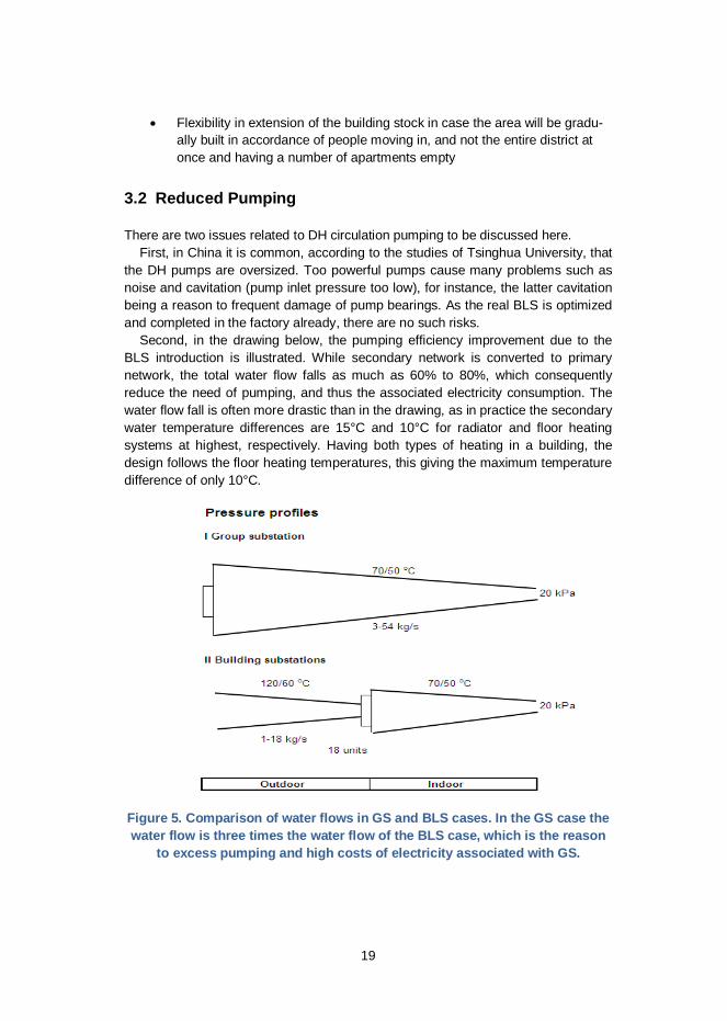
3.2 Reduced Pumping
There are two issues related to DH circulation pumping to be discussed here.First, in China it is common, according to the studies of Tsinghua University, that
the DH pumps are oversized. Too powerful pumps cause many problems such asnoise and cavitation (pump inlet pressure too low), for instance, the latter cavitationbeing a reason to frequent damage of pump bearings. As the real BLS is optimizedand completed in the factory already, there are no such risks.
Second, in the drawing below, the pumping efficiency improvement due to theBLS introduction is illustrated. While secondary network is converted to primarynetwork, the total water flow falls as much as 60% to 80%, which consequentlyreduce the need of pumping, and thus the associated electricity consumption. Thewater flow fall is often more drastic than in the drawing, as in practice the secondarywater temperature differences are 15°C and 10°C for radiator and floor heatingsystems at highest, respectively. Having both types of heating in a building, thedesign follows the floor heating temperatures, this giving the maximum temperaturedifference of only 10°C.
Figure 5. Comparison of water flows in GS and BLS cases. In the GS case thewater flow is three times the water flow of the BLS case, which is the reason
to excess pumping and high costs of electricity associated with GS.

20
All in all, the life cycle costs of BLS with extended primary network during 20 yearsto come make BLS very competitive to the traditional GS having troublesome sec-ondary networks.
The network layout can be better optimized when having BLS instead of the tradi-tional GS as illustrated in Fig. 6 below. The GS is often in the middle of the con-nected buildings, which causes some pipes to follow the route back to the buildingsthat the primary network had already passed by. Moreover, installing two primarypipes is more flexible than 2–6 secondary pipes in between the densely constructedbuildings and other technical infrastructure already in the ground, telecommunica-tion and electric cabling, water and sewage piping.
3.3 Optimal Underground Piping
Introduction of BLS will both reduce the diameter and geographical length of theunderground network, often also the number of the pipes to be installed. The re-duced length is based on the new layout of the pipes as illustrated in Fig. 6 below.
Figure 6. BLS helps reduce the piping route length.
As the water flow in the secondary network is large requiring several and largepipes, the BLS introduction will reduce the diameter and number of the pipelineswhen converting the secondary to the primary network. Reduced diameter implieslower investment costs on piping, usually the network being the largest componentof the DH fixed assets.
The BLS will likely cause energy savings in the buildings as the temperature con-trol is building specific and can be tuned according to the heating behavior of theparticular building. This cannot be done with the traditional GS which serves 10–20buildings collectively, and the heating quality needs to be adjusted to the most criti-cal building, while the others will receive excess heat from time to time.
GS with secondary network BLS with extended primary network

21
3.4 Improved Energy Efficiency
Some of the experiences from the heat energy savings after having had convertedthe GS to BLS have been:
• In Central Europe, conversion of old GS systems to modern BLS systemshas reduced heat consumption by 15% on average, thus making DH moreenergy efficient and competitive on the market.
• In Weihai, Shandong, there have been indications that BLS systems useheat energy 12% less than GS systems.
• In Chengde, there are indications that the BLS saves 11% of the heat con-sumption compared with GS2.
Remote communication may provide benefits in reduced maintenance and energyconsumption.
2 Disrict Heating 6/2014
22
4. Ownership and Cost Sharing
4.1 Property Borders
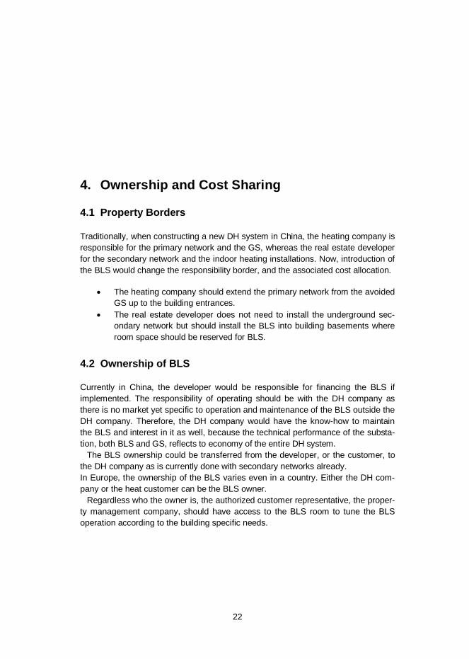
Traditionally, when constructing a new DH system in China, the heating company isresponsible for the primary network and the GS, whereas the real estate developerfor the secondary network and the indoor heating installations. Now, introduction ofthe BLS would change the responsibility border, and the associated cost allocation.
The heating company should extend the primary network from the avoidedGS up to the building entrances.
The real estate developer does not need to install the underground sec-ondary network but should install the BLS into building basements whereroom space should be reserved for BLS.
4.2 Ownership of BLS
Currently in China, the developer would be responsible for financing the BLS ifimplemented. The responsibility of operating should be with the DH company asthere is no market yet specific to operation and maintenance of the BLS outside theDH company. Therefore, the DH company would have the know-how to maintainthe BLS and interest in it as well, because the technical performance of the substa-tion, both BLS and GS, reflects to economy of the entire DH system.
The BLS ownership could be transferred from the developer, or the customer, tothe DH company as is currently done with secondary networks already.In Europe, the ownership of the BLS varies even in a country. Either the DH com-pany or the heat customer can be the BLS owner.
Regardless who the owner is, the authorized customer representative, the proper-ty management company, should have access to the BLS room to tune the BLSoperation according to the building specific needs.

23
4.3 Cost Sharing
Based on the calculations and experiences, the costs of the two parties do notchange much, when the BLS system will be chosen instead of the traditional GSsystem in a new construction area. Therefore, there seems not to be any substan-tial financial barrier to introduce BLS. Rather the problem seems to be how to findroom space in the building to install the BLS. Sometimes, as in Weihai, Shandongprovince, the BLS units were installed in separate steel plate covered boxes near tothe heated buildings.
Nevertheless, the investment cost sharing between the DH company and the de-veloper should be clear. The current responsibilities seem simple and fair: The DHcompany invests in primary network extension to the room of the BLS and the de-veloper invests in the BLS and the indoor heating system.
In Europe various cost sharing ways are applied, even in one company. The cus-tomer may choose whether he wishes to own the substation or not. If yes, his an-nual payments to the DH company will be lower than if the DH company would ownthe BLS.

24
5. Institutional Barriers to be Addressed
5.1 Slow Commissioning of BLS
There have been BLS units in operation for several years in various parts of China,but still very little analyzed information is available on their real performance interms of energy efficiency.
So far, there have been challenges to commission and analyze BLS in China dueto institutional resistance, which has been seen in the following forms:
The BLS changes the responsibility border between the parties, theDH company and the real estate developer. The parties do not see anincentive to work over the traditional border to facilitate BLS.
The technical design institute has little or no experience in the BLSconcept, its design, requirements and benefits. Therefore, it rather de-signs traditional solutions.
DH operators have had little or no trust in the independent and auto-matic operation of the BLS, but the automation may have beenswitched off and the BLS has been operated manually. Therefore, thecollected data is not completely relevant for analyses.
The DH companies, after the international financing is over, have notalways shown interest in recording and giving metered data for theanalysis to be carried out by an external body.
5.2 No Competition at Present
In China, there is no competition in the DH sector as the customers are more orless obliged to connect DH. Nevertheless, in Europe and America the DH compa-nies need to be competitive on the market at all times, and if not, a customer mayswitch to other heating modes, and new customers will not connect any more.
Lack of competition does not provide strong incentives to the DH company to takecare of the heating quality and costs of the customer.

25
5.3 Different Interest of DH Company and Developer
An institutional barrier concerns the interest of the heating company and the devel-oper:
Heating company may wish to minimize the life cycle costs as it will be re-sponsible for operation of the system in the future. Given that, the opera-tion costs including water, heat and electricity losses as well as repaircosts are important to run the business. The lower the costs are, the high-er the profit would be unless the regulator distributes the cost savings tothe end-user tariffs.
Real estate developer wishes to sell the apartments at high profit. There-fore, it tries to minimize the investment cost related to heat supply, thus of-ten yielding to poor materials and poor construction quality.
Then, after the building has been commissioned, usually the heating company hasto take over the operation of the secondary network, the construction of which wasout of the company’s quality control.
5.4 Lump-sum Tariff
The heat customer, paying a lump sum for DH regardless the quality and energy hehas received, is not interested in energy saving.
The DH company having a constant cash flow, based on the lump sum tariff, hasan incentive to minimize the fuel costs as a means to gain profit. From time to time,this may compromise the heating quality of the customers. The customers being atthe far end of the distribution network suffer more for the inadequate heating qualitywhereas the other ones being closer to the heat source, the GS, may have evenexcess heat to be ventilated out from the windows. Typically, there prevails imbal-ance of heating quality in the secondary networks at present.

26
6. Technical Issues
6.1 Make-up Water
There are three alternatives to supply make-up water to the indoor heating system,as follows:
First, city water will be taken and stored in an open basin and softenedbefore supply to the heating system. The water storage basin and thesoftening system need relatively much room space which is costly. Onthe other hand, the price of the city water is lower than the price of thetreated primary network water.
Second, the primary network water can be tapped to the indoor heat-ing system. As the treated water is relatively more expensive, the wa-ter management in the indoor heating systems should be good: nowater losses and expansion tank.Third, the city water is taken directly from the city water network andled to the indoor heating system without any open air basin. Typicallyin Europe and America, mainly this third alternative is used whichleads to make-up water savings.
6.2 Expansion Compensation
Based on water physics, both water volume and density change along with thetemperature variations. At present, the expansion is compensated by the overflowvalve. As the pressure increases, the valve opens and releases excess water to thesewage or the open-type make-up water tank.
In China for the time being, the water losses in the secondary side are so highthat there is no possibility to closed water circulation in the secondary side. Make-up water flow is constant ranging from 1 to 3% of the secondary circulation waterflow.
As the BLS will become more common, and the make-up water flow will substan-tially reduce, expansion tanks can be installed to the BLS. In such a way, the waterlosses will reduce even more, and almost vanish. Thus, the indoor piping systemwould become a closed loop without constant make-up water need.

27
6.3 One- or Two Way Control
In China, the communication functions in two-ways. Measured data can be collect-ed both into controller of the substation or remotely to the control center. The con-trol center may locate either at the main heat source or at the headquarters of theDH company. Second, by means of remote control system, the operator can remotemanipulate the set values of the pumps and valves at the substation, thus by-passing the local automation of the substation.
Moreover, if the number of the substations is high, the operator staff is not able tomanage the substations other than relying on the electronic automation systemsfunctioning in the substations already.
In China, there have been examples that the set value manipulation, while by-passing the automation of the substation, has caused excess heating costs.
While analyzing the remote metered data, the operator can identify those substa-tions in which the measured data seem abnormal, and if so, send a maintenancestaff to check the substation functioning. Such indicators of abnormal operationcompared to measured date from the other substations are, for instance:
The difference of supply and return temperature is very low, which may in-dicate there is excess pumping in the secondary side. This can be correct-ed by reduced pumping.
The make-up water losses are high. Either there is a leakage to be re-paired or the customer illegally taps water for his own needs.
Heat consumption is high/low per heated area, which indicates there is aneed to adjust the temperature values of the control systems of the substa-tion.
Alarms of unexpected events of doubtful data
6.4 Heat Exchanger Design
Often the rubber sealed heat exchangers are undersized, which is one reason tosmall temperature difference on the secondary side. Another reason is excesspumping caused by too powerful pumps.
In order to have the heat exchangers adequately sized, there is a non-profitstandardization institute AHRI based in the USA. AHRI is the only third party heatexchanger verification institute in the world. Most international heat exchangermanufacturers are members of AHRI.
AHRI Standard 400 is a global standard stipulating the verification of thermal per-formance of liquid-to-liquid heat exchangers.

28
Figure 7. Label and contact information of AHRI.
AHRI uses the “AHRI Liquid To Liquid Heat Exchangers (LLHE) Certification Pro-gram” to verify the heat exchanger performance.
The manufacturers are forced to deliver their heat exchanger design softwareprograms to AHRI. Whenever there is any doubt the heat exchanger does not meetthe required temperature values, AHRI can be asked to test the particular heatexchanger. The costs of the testing shall be paid by the manufacturer in case theheat exchangers failed, or the requestor, if the heat exchanger met the set require-ments.
6.5 Heat Meter Reading Combined with Remote Controlling
Regular heat meter reading is vital in case consumption based billing is used.In China, the consumption based billing is still to expand outside the already exist-ing pilot cities.
As ways to collect metered heat consumption, the following options are available:
Automatic remote reading through the SCADA Mobile remote reading by means of car driving in the neighborhood of the
buildings Manual recording on the paper cards that the customer shall fill-in and mail
to the DH company at the end of each month.
Consumption based billing is used 100% in the EU, North-America, and South-Korea on the building level. Apartment level metering is rarely applied as billing asthere are both excess costs and inaccuracies related to apartment level heat meter-ing. Those apartment level meters already existing are often used to allocate theheat consumption of the building to the apartments. Specific heat cost allocators areused often to allocate the heating costs of the building to the apartments.

29
Figure 8. The BLS for up to 24 floors in building with two heat exchangers andcontrol systems, one for floors 1–12 and the other one for 13–24. More heat
exchangers and control systems can be added if more floors exist in the par-ticular building. No changes in the primary network are needed.
The main components of the BLS comprise the heat exchanger (orange color) sep-arating the primary and the secondary water networks, the temperature controlvalves (pink), outdoor temperature controller (light blue) and the heat energy meter(light red) with two temperature sensors and one water flow sensor. The water flowsensor is installed in the return pipe on the primary side.
The substation automation is the same in GS and BLS, but with in BLS it worksmore accurately as being specific to the individual building. The automation regu-lates the heat supply by means of two measurements, as follows:
The outdoor temperature measurement tells to the temperature controllerhow much heat is needed.
The supply temperature of the secondary/indoor piping tells to the control-ler how much heat is currently supplied to the buildings or buildings.
The controller regulates the control valve by opening if more heat is needand throttling if less heating is needed.
The automation system shall be tuned according to the requirements of the con-nected heat load. Basically, the tuning is very simple: The set value of the supply
Borders of substationOutdoortemperature
Supply from DH T
Upperfloors
Control Lowervalves floors
Return to DH T
Flow meter
Heatmeter
Control 2
1
2
Control 1
30
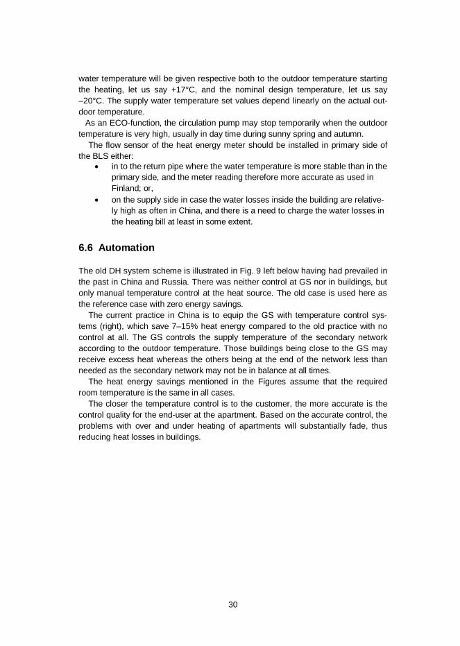
water temperature will be given respective both to the outdoor temperature startingthe heating, let us say +17°C, and the nominal design temperature, let us say–20°C. The supply water temperature set values depend linearly on the actual out-door temperature.
As an ECO-function, the circulation pump may stop temporarily when the outdoortemperature is very high, usually in day time during sunny spring and autumn.
The flow sensor of the heat energy meter should be installed in primary side ofthe BLS either:
in to the return pipe where the water temperature is more stable than in theprimary side, and the meter reading therefore more accurate as used inFinland; or,
on the supply side in case the water losses inside the building are relative-ly high as often in China, and there is a need to charge the water losses inthe heating bill at least in some extent.
6.6 Automation
The old DH system scheme is illustrated in Fig. 9 left below having had prevailed inthe past in China and Russia. There was neither control at GS nor in buildings, butonly manual temperature control at the heat source. The old case is used here asthe reference case with zero energy savings.
The current practice in China is to equip the GS with temperature control sys-tems (right), which save 7–15% heat energy compared to the old practice with nocontrol at all. The GS controls the supply temperature of the secondary networkaccording to the outdoor temperature. Those buildings being close to the GS mayreceive excess heat whereas the others being at the end of the network less thanneeded as the secondary network may not be in balance at all times.
The heat energy savings mentioned in the Figures assume that the requiredroom temperature is the same in all cases.
The closer the temperature control is to the customer, the more accurate is thecontrol quality for the end-user at the apartment. Based on the accurate control, theproblems with over and under heating of apartments will substantially fade, thusreducing heat losses in buildings.

31
Figure 9. Reference case with manual control at heat source only (left) andthe current Chinese practice to have the automatic temperature control ateach GS (right). The energy savings of the automatic GS reach from 7% to15% relative to the reference case. The blue squares indicate temperaturecontrol whereas the white squares without such control.
Figure 10. The GS (left) is replaced by BLS (right). Simultaneously, the tem-perature control has moved from GS to each BLS, where the temperaturecontrol can be tuned to reflect the behavior of the particular building. Theheat energy savings range from 10 to 20% compared to the reference case.
In China, as in all countries in the world, people want to have a constant improve-ment on the living quality. It may mean better or more food, better possibilities totravel, larger variety of entertainment, etc. Improving quality of heating is certainlyone of those trends of wanting. The heating quality means that room temperaturesmust stay adequate and stable to meet the increasing requirements of living comfort.To meet the requirements, the BLS offers a response better than the current GS.
The control isalso in BLS
32
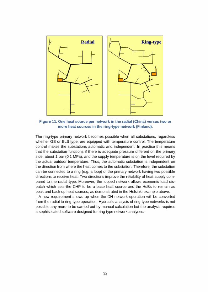
Figure 11. One heat source per network in the radial (China) versus two ormore heat sources in the ring-type network (Finland).
The ring-type primary network becomes possible when all substations, regardlesswhether GS or BLS type, are equipped with temperature control. The temperaturecontrol makes the substations automatic and independent. In practice this meansthat the substation functions if there is adequate pressure different on the primaryside, about 1 bar (0.1 MPa), and the supply temperature is on the level required bythe actual outdoor temperature. Thus, the automatic substation is independent onthe direction from where the heat comes to the substation. Therefore, the substationcan be connected to a ring (e.g. a loop) of the primary network having two possibledirections to receive heat. Two directions improve the reliability of heat supply com-pared to the radial type. Moreover, the looped network allows economic load dis-patch which sets the CHP to be a base heat source and the HoBs to remain aspeak and back-up heat sources, as demonstrated in the Helsinki example above.
A new requirement shows up when the DH network operation will be convertedfrom the radial to ring-type operation. Hydraulic analysis of ring-type networks is notpossible any more to be carried out by manual calculation but the analysis requiresa sophisticated software designed for ring-type network analyses.
Radial Ring-type

33
Figure 12. Control screen of substation.
6.7 IT Tools for Optimization
Appropriate software helps district heating companies improve energy efficiency,increase security of supply and save on costs. Two internationally used softwaretools of Enoro are mentioned here.
Enoro’s GRADES Heating software is a network calculation and simulation toolthat is used to improve overall network design and operation. The graphical userinterface includes a map view for visual network design and simulation calculations.When the design of a DH network must be changed – for example to add BLS units,heating consumers, or network areas – GRADES Heating helps find the optimalnew network dimensioning (sizing for pipes, pumps and valves), to increase energyefficiency and save on costs without reducing security of supply. In daily DH opera-tions, GRADES Heating can be used to evaluate different scenarios to find the bestnetwork operation plan for the coming days.

34
The GENERIS energy information system provides a measurement data ware-house for the centralized management of all measurement data measured from DHnetworks. Collection of measurement data from as many network locations as pos-sible provides valuable information about the status and dynamics of the entire DHnetwork. In addition, measurement data can be used to improve the accuracy ofnetwork simulations. When GENERIS is also given data about the costs of heatproduction (e.g. production plants and fuel costs) and about sales models (i.e. salescontracts and tariffs), the system will provide the heating company with a completeand detailed overview of their entire heating business as a basis for planning futurebusiness operations.
Figure 13. Example of looped network optimization with GRADES software.
6.8 Noise
The BLS units are silent as they are both designed and tested in the factory alreadyto be installed in the living environment not to disturb anybody. The smallest substa-tions can be installed in the living rooms, when the substations are apartment levelsubstations, as show in Picture below.
The noise level of BLS is below 35 dB, which is mainly caused by the water flowing inthe pipes. Also some little noise comes from the controller as it is knocking when doingthe controlling work. As wet pumps are used, the pumps are silent and noiseless.

35
Figure 14. Two apartment level substations for 150 m2 (left) and 300 m2 (right)heated areas including both DHW and SH services.
6.9 Safety
The BLS is equipped with an excess pressure valve, e.g. a safety valve, whichreleases the excess pressure out of the BLS and the DH system.
The high pressure and temperature up to some 10 bar and 120oC, respectively,can temporarily prevail in the primary network in the entrance of the substation. Thepipes are from steel usually of PN16, which is designed for normal use in 16 barpressure.
If problems occur, they start with small leakages in seams, which will be detectedby the moist sensor located in the substation room or by the visual inspection regu-larly, once a week, for instance, carried out by the operation staff in the substationroom.

36
Annex 1: Sino-Fin Comparison of DH
The main differences between Finland, and typical to many countries in the EU, andChina are collected to the table below.
Table 5. Comparison.
Issue China FinlandClimatic condi-tions
35–55o Latitude; -10...-35oC minimum tempera-ture
60–70o latitude;-25...-35oC minimum tempera-ture
New buildingcode
New buildings with 50% ener-gy reduction from the 1980-1982 building code
Low energy buildings from2012 on
Status of DH Strongly expanding 13–18% /a Rather saturated market, 1%/agrowth
Products ofDH
Only room heating: DH systemruns during heating seasononly (5–7 months); DHW usu-ally with solar collectors
Both room and DHW heating:DH runsall year round
Type of roomheating
Either radiator or floor heating Radiator heating mainly
Heat metering Rather common in group sub-stations already, but rarely inbuildings
Always in buildings
Number ofenterprises
Several per city (In Tianjinused be 420 DH companies 10years ago)
Usually one DH company percity but not regulated by anybody
Heat tariffs Fixed Yuan/m2 Two tier tariffs based on me-tered heat consumption
Basis of heatbilling
Building norms Metered heat consumption

37
Heat distribu-tion
DH company delivers via pri-mary network to group substa-tions, from which further on viesecondary networks to build-ings
DH company delivers via pri-mary network directly to the buildings, where build-ing level substations
DH sectorregulation
Strictly regulated, sociallymotivated
Almost no regulation but mar-ket based business
Specific heatconsumption
100–200 kWh/m2 130 kWh/m2 including domes-tic hot water130 kWh/m2
Quality ofheating ser-vices
No heating in early autumnand late spring, sometimesinadequate room temperaturesin winter (World Bank custom-er surveys)
Comfortable heating servicesall year round, customers arehighly satisfied according tothe surveys carried out.
Type of net-works
Branched: one heat source pernetwork
Looped: several heat sourcesin one network
Expectedlifetime of thenetwork pipe-lines
10–30 years. The main prob-lem is the corrosion in thesecondary networks10–30
Longer than 50 years. At pre-sent, only 0.5% of the net-works country wide are re-placed annually (equals to 200years lifetime)
Circulationwater losses
The water losses are typicalhigh 1–3% of the water flow.
Water losses are low: 0.08%of the water flow.
Circulationwater quality
Water quality is poor and cor-rosive in the secondary side.
Good quality of water and nocorrosion.
Heat produc-tion
About 35% from huge CHPplants and the rest 65% fromcoal fired water boilers of 29 to64 MW and a little from indus-trial processes
70% from CHP, 30% fromindustry and heat only boilersources
Heat produc-tion capacity
About 100% of peak load, noback up
120..200% of peak loadincluding back-up
Fuel More than 95% domestic coal Mix of bio mass (31% in 2014),natural gas (22%), coal (24%),peat (13%); oil (3%), wasteheat and other (7%)
Corporatestructure
CHP state owned, DH cityowned, secondary networksowned by customers
DH and CHP mainly cityowned in one company, nosecondary networks
DH company Operation and maintenancefocused utilities
Full scale business units
38
Annex 2: Substation for connecting the buildingto heating networks
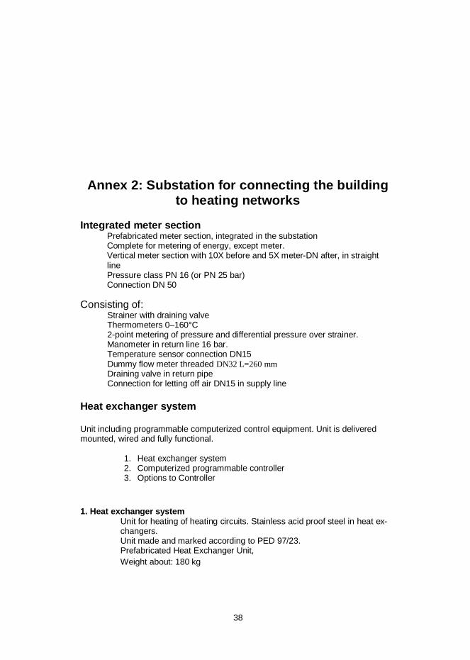
Integrated meter sectionPrefabricated meter section, integrated in the substationComplete for metering of energy, except meter.Vertical meter section with 10X before and 5X meter-DN after, in straightlinePressure class PN 16 (or PN 25 bar)Connection DN 50
Consisting of:Strainer with draining valveThermometers 0–160°C2-point metering of pressure and differential pressure over strainer.Manometer in return line 16 bar.Temperature sensor connection DN15Dummy flow meter threaded DN32 L=260 mmDraining valve in return pipeConnection for letting off air DN15 in supply line
Heat exchanger system
Unit including programmable computerized control equipment. Unit is deliveredmounted, wired and fully functional.
1. Heat exchanger system2. Computerized programmable controller3. Options to Controller
1. Heat exchanger systemUnit for heating of heating circuits. Stainless acid proof steel in heat ex-changers.Unit made and marked according to PED 97/23.Prefabricated Heat Exchanger Unit,Weight about: 180 kg

39
Unit equipped with sensors for measuring of temperature of incoming primary andsecondary media.Sensors replace thermometers for temperature reading.Primary supply equipped with a summer shut off valve for Heating 1Needed dearation connections included and drainings with sealed flush valves.The heat exchanger is insulated with CFC-free PU-foam, with an ABS surface. Theinsulation is easy to mount and dismount.Steel pipes in the system are painted.
Heating 1 secondary side with:Ball valve in return pipeBalancing valve in supply line DN80Safety pressure relief valve, DN25, 6.0 barFilling of secondary side of type EN1717 EA.Connection for expansion line DN25 Strainer in return line
Manometer for pressure and differential pressure reading 3 points, 0–6 bar
Circulation pumpFlow 6.09 l/s, lifting height 85 kPa
The pump has alarm signal, is prepared for external on/ off control, and has controlinput for 0–10V.External pipe connection DN80
2. Computerised controllerHardware is mounted in an electrical cabinet. It includes applications and functionsfor control and monitoring of the heating unit.Controler has an inbuilt display, and can even in simplest version communicate viaWEB, OPC and ModBus both RTU and IP, without options and add-ons. A modemport is also included.M-Bus, Lon, advanced WEB, BacNet and other options included in delivery arelisted under 3. - options below.Controller can be integrated and communicate with most Building ManagementSystems (BMS) and supports open communication standard like TCP/IP OPC andLON.Optional communication module can be installed also afterwards, not needed to bepart of initial delivery. The software can be replaced by use of the inbuilt SD-cardreader.Controller shall be completely installed, programmed and wired. Basic function ofhardware and software, as well as sensors, actuators, pump control functions shallbe tested before shipment.

40
Control functionsHeatingOutdoor compensated heating supply temperature is used. An outdoor sensor anda heating curve determines the wanted supply temperature of the heating supply.The heating curve is a 5 points curve + min and max value, adjustable at differenttemperatures.ECO-function heatingNeed- based control of control valves and pumps. At warm outside temperature allcontrol valves closes, and the pump stops. Pump and valve exercise is performedat adjustable times.
The controler shall be always prepared for the following functions:Reading of pulses from energy meter and/ or cold water meter.Limiting/ control of difference between the primary return and the secondary returntemperatures. When this difference is too high, this function limits the opening of thecontrol valve, in order not to use more than necessary capacity and limit primaryflow.Limiting of return temperature primary side. Different settings depending on season.Capacity or flow limitation.
Alarm functionsController has alarms for temperature deviations, sensor faults, pump alarms andexternal alarm inputs. Alarm message can be sent as E-Mail or SMS if unit is con-nected to internet, or via an optional Modem.
CommissioningStartup is made according to instructions in the manual in the shipping documenta-tion. Support available via .(contact of the manufacturer).
3. Options included in deliveryThese options are ordered and is part of the delivery:
- Advanced webserver
Advanced WEB- function, built in web server. Gives a graphical interface over theunits functions. A large memory holds historical data ( >20 years!) that can be pre-sented in the user interface. All settings, optimizations and alarm handling can bemade via this user interface. No licenses, no programs needed, no web-hotels etc.Only a PC with a web browser program is needed. Internet connection on both theController and the PC is needed.
Alarms as SMS to mobile phones via TCP/IP is prepares, as well as e-mail alarm.A report function shall be included in Controller. It is a function monitoring systemfor historical data of the unit. The Report component shall have several loggers,

41
with different time horizons. In the user interface can be monitored 1, 2, 3 or 8 daysof values in a graph, or as values in a table.It shall be possible to download all stored data since the Controler was started up 8every 10 minutes a value- set is saved. This data shall be accessible in an Excel fileautomatically created on demand.The electrical cabinet shall be prepared with a 2 meter TCP/IP net work cable, thatshould be connected to the internet-supplier’s network socket. Internet connection,subscription and socket are not part of this delivery.
-Meter value communicationTransmitting of meter values from energy meter and/ or cold water meter with M-Bus. Values gathered from the energy meter are volume, energy, capacity, flow andtemperatures.
-Pressure sensor 0–10 barPressure sensor 0–10bar, output 0–10V (24V AC supply) for measuring of pressurein secondary side heating.
Design data:Available differential pressure min: 100 kPaPressure NormPN 16 (or PN 25)Heating 1Capacity 500 kWTemperature 120-63.8 / 60-80 °CFlow 2.24 / 6.09 l/sPressure drop 2 / 14 kPa
Control equipment:ControllerHeating 1Temperature sensor QAZ21.5220-150Sec. return sensor QAD21/209Prim. Return sensor QAD21/209Outdoor sensor QAC 222-way control valve VVF53 DN40 Kvs16.00, 25 kPaActuator SKD 60Sensors primary sideSensor primary return QAD21/209Sensor primary supply QAD21/209
Control equipment with sensors and actuators are internally wired. Outdoor sensoris supplied but not wired. Commissioning not included.

42
Supplied pumps are electrically wired. For 1-phase pumps for heating >6 A, HotWater Circulation pumps > 2 A, double pumps and all 3-phase pumps only alarmand control wiring is made. Electrical main supply for pumps must then be done onsite according to local regulations.
TECHNICAL SPECIFICATION TABLE
HEAT EXCHANGERS Unit Heating 1ManufacturerTypeLoad kW 500
Prim. Sec.Temperature °C 120-63.8 60-80Flow l/s 2.24 6.09Pressure drop kPa 2 14PED - category Cat 1Material AISI 316Control equipment Heating 1ManufacturerControllerControl ValveFlow l/s 2.24Pressure drop kPa 25Size / kvs DN/kvs 40/16.00Actuator SKD 60Control signal/Voltage V 24V / 0-10VPUMPS Heating 1ManufacturerTypeFlow l/s 6.09Head kPa 70Power / Current W / A 769/ 3.38Voltage V 230, 1 phaseNETWORK, EXPANSION- AND SAFETY EQUIPMENT Heating 1Network volume / lifting head for network l/kPa / 50Expansion tank volume / prepressure l/kPa /Safety valve size / relief pressure DN/bar DN25/6.0SECONDARY SIDE PIPE EQUIPMENT Heating 1Pressure drop kPaPIPE SIZESDistrict heating flow/return DN50Heating flow-return, pressure drop for pipes and components DN80

43
OPTIONAL COMPONENTS: Measurementsand calculationvalues
Balancing valve for heating / Pressure Drop (kPa)Manometer module for heating / secondaryside 3 points, 0–6 barFilling H1Summer Shut Off Valve Heating1Painting of steel Pipes
Pressure sensor 0-10 bar, 0-10 V, 24V ACIQ Web200 ( Incl. WEBServer, Report, E-mail alarm)IQ Meter 200 ( M-Bus, meter communication)
ADDITIONAL INFORMATION: Temperatures read from control center.PED-category for substation Cat 1Calculated available differential pressure of primary heating network min 100 kPa /max600 kPaIntegrated meter section with inlet strainer, sensor pockets and thermometers. Verticalreturn line with meter dummyThreaded, DN 32, 260 mm.Pressure metering in 3 points,16 bar.

44
Sponsors:
Finnish Energy Industrieshttp://www.energy.fi
Beautiful Beijing – Finprohttp://www.finpro.fi
City of Turku
Alfa Laval Nordic http://www.alfalaval.fi
Enorohttp://www.enoro.fi
Kolmeks http://www.kolmeks.fi
Högfors valveshttp://www.hogfors.fi
Vexve
Frans Rantapere | Sales Manager | Tel. +358 40 588 3330 |[email protected] Oy | Pajakatu 11 | FI-38200 Sastamala | FINLAND |http://www.vexve.com
Series title and number
VTT Technology 231
Title Building level substation – the innovation of district heating system
Author(s) Kari Sipilä, Arto Nuorkivi & Jorma Pietiläinen
Abstract The building level substation (BLS) is suggested here as an innovation to the District Heating (DH) sector development in China. Introduction of the BLS would provide obvious benefits in improved energy efficiency and living comfort, but it also faces institutional barriers to overcome. CHP concept will be described, and the economic, institutional and technical issues associated to BLS will be addressed. The BLS units are prefabricated compact products that are designed, manufactured and tested at the factory ready for transportation to the construction site, where the complete BLS unit will be mounted to the floor, connected to the existing indoor piping of heating and water, the remote communication facilities as well as to power supplies of the building. The BLS as an integrated plate heat exchange unit shall be prefabricated and assembled and successfully tested both hydraulically and electrically in the factory already to meet the high functional and low noise requirements, and if he so wishes, at the presence of the Borrower's representative. Its base and brazed structures should have sufficient intensity and stability. Domestic hot water (DHW) can also be integrated to DH. BLS makes it possible to complement the DH with DHW afterwards at low incremental costs: a small heat exchanger and a small circulation pump as well as connection to the existing DHW and city water piping are needed.
ISBN, ISSN, URN ISBN 978-951-38-8348-5 (Soft back ed.) ISBN 978-951-38-8349-2 (URL: http://www.vttresearch.com/impact/publications) ISSN-L 2242-1211 ISSN 2242-1211 (Print) ISSN 2242-122X (Online) http://urn.fi/URN:ISBN:978-951-38-8349-2
Date October 2015
Language English
Pages 35 p. + app. 9 p.
Name of the project BLS Manual
Commissioned by Finnish Energy, Finpro, City of Turku, Alfa-Laval, Enoro, Kolmeks, Högfors and Vexve
Keywords District heating, heating substation, building
Publisher VTT Technical Research Centre of Finland Ltd P.O. Box 1000, FI-02044 VTT, Finland, Tel. 020 722 111

The building level substation – the innovation of district heating system The building level substation (BLS) is suggested here as an innovation to the District Heating (DH) sector development in China. The BLS units are prefabricated compact products that are designed, manufactured and tested at the factory ready for transportation to the construction site, where the complete BLS unit will be mounted to the floor, connected to the existing indoor piping of heating and water, the remote communication facilities as well as to power supplies of the building. Domestic hot water (DHW) can also be integrated to DH. BLS makes it possible to complement the DH with DHW afterwards at low incremental costs: a small heat exchanger and a small circulation pump as well as connection to the existing DHW and city water piping are needed.
ISBN 978-951-38-8348-5 (Soft back ed.) ISBN 978-951-38-8349-2 (URL: http://www.vttresearch.com/impact/publications) ISSN-L 2242-1211 ISSN 2242-1211 (Print) ISSN 2242-122X (Online) http://urn.fi/URN:ISBN:978-951-38-8349-2
•VISIONS•S
CIE
NC
E•T
ECHNOLOGY•R
ES
EA
RC
HHIGHLIGHTS
231
The building level substation – the innovation of district heating system Kari Sipilä | Arto Nuorkivi | Jorma Pietiläinen