The Brookhaven muon storage ring magnet
24
q The construction of this magnet was supported by the US Department of Energy and by the US}Japan Program for Cooperation in High Energy Physics. * Corresponding author. Tel.: # 1-631-344-4771; fax: # 1-631-344-4067. E-mail address: bunce@bnl.gov (G. Bunce). Nuclear Instruments and Methods in Physics Research A 457 (2001) 151}174 The Brookhaven muon storage ring magnet q G.T. Danby!, L. Addessi!, Z. Armoza!, J. Benante!, H.N. Brown!, G. Bunce!,*, J.C. Cottingham!, J. Cullen!, J. Geller!, H. Hseuh!, J.W. Jackson!, L. Jia!, S. Kochis!, D. Koniczny!, R. Larsen!, Y.Y. Lee!, M. Mapes!, R.E. Meier!, W. Meng!, W.M. Morse!, M. O'Toole!, C. Pai!, I. Polk!, R. Prigl!, Y.K. Semertzidis!, R. Shutt!, L. Snydstrup!, A. Soukas!, T. Tallerico!, F. Toldo!, D. Von Lintig!, K. Woodle!, R.M. Carey", W. Earle", E.S. Hazen", F. Krienen", J.P. Miller", J. Ouyang", B.L. Roberts", L.R. Sulak", W.A. Worstell", Y. Orlov#, D. Winn$, A. Grossmann%, K. Jungmann%, G. zu Putlitz%, P. von Walter%, P.T. Debevec&, W.J. Deninger&, D.W. Hertzog&, S. Sedykh&, D. Urner&, M.A. Green’, U. Haeberlen), P. Cushman*, S. Giron*, J. Kindem*, D. Miller*, C. Timmermans*, D. Zimmerman*, V.P. Druzhinin+, G.V. Fedotovich+, D.N. Grigorev+, B.I. Khazin+, N.M. Ryskulov+, S. Serednyakov+, Yu.M. Shatunov+, E. Solodov+, K. Endo,, H. Hirabayashi,, Y. Mizumachi,, A. Yamamoto,, S.K. Dhawan-, A. Disco-, F.J.M. Farley-, X. Fei-, M. Grosse-Perdekamp-, V.W. Hughes-, D. Kawall-, S.I. Redin- !Brookhaven National Laboratory, Upton, NY 11973, USA "Department of Physics, Boston University, Boston, MA 02215, USA #Newman Laboratory, Cornell University, Ithaca, NY 14853, USA $Fairxeld University, Fairxeld, CT 06430, USA %Physikalisches Institut der Universita ( t Heidelberg, 69120 Heidelberg, Germany &Physics Department, University of Illinois at Urbana-Champaign, Urbana-Champaign, IL 61801, USA ’Lawrence Berkeley Laboratory, Berkeley, CA 94720, USA )Max Planck Institiut fu ( r Medizinische Forschung, 69120 Heidelberg, Germany *Department of Physics, University of Minnesota, Minneapolis, MN 55455, USA +Budker Institute of Nuclear Physics, Novosibirsk, Russia ,KEK, High Energy Accelerator Research Organization, Tsukuba, Ibaraki 305-0801, Japan -Department of Physics, Yale University, New Haven, CT 06511, USA Received 9 May 2000; accepted 15 June 2000 0168-9002/01/$ - see front matter ( 2001 Elsevier Science B.V. All rights reserved. PII: S 0 1 6 8 - 9 0 0 2 ( 0 0 ) 0 0 7 0 4 - X
Transcript of The Brookhaven muon storage ring magnet

qThe construction of this magnet was supported by the US Department of Energy and by the US}Japan Program for Cooperation inHigh Energy Physics.
*Corresponding author. Tel.: #1-631-344-4771; fax: #1-631-344-4067.E-mail address: [email protected] (G. Bunce).
Nuclear Instruments and Methods in Physics Research A 457 (2001) 151}174
The Brookhaven muon storage ring magnetq
G.T. Danby!, L. Addessi!, Z. Armoza!, J. Benante!, H.N. Brown!, G. Bunce!,*,J.C. Cottingham!, J. Cullen!, J. Geller!, H. Hseuh!, J.W. Jackson!, L. Jia!, S. Kochis!,
D. Koniczny!, R. Larsen!, Y.Y. Lee!, M. Mapes!, R.E. Meier!, W. Meng!,W.M. Morse!, M. O'Toole!, C. Pai!, I. Polk!, R. Prigl!, Y.K. Semertzidis!, R. Shutt!,L. Snydstrup!, A. Soukas!, T. Tallerico!, F. Toldo!, D. Von Lintig!, K. Woodle!,
R.M. Carey", W. Earle", E.S. Hazen", F. Krienen", J.P. Miller", J. Ouyang",B.L. Roberts", L.R. Sulak", W.A. Worstell", Y. Orlov#, D. Winn$, A. Grossmann%,
K. Jungmann%, G. zu Putlitz%, P. von Walter%, P.T. Debevec&, W.J. Deninger&,D.W. Hertzog&, S. Sedykh&, D. Urner&, M.A. Green', U. Haeberlen), P. Cushman*,
S. Giron*, J. Kindem*, D. Miller*, C. Timmermans*, D. Zimmerman*,V.P. Druzhinin+, G.V. Fedotovich+, D.N. Grigorev+, B.I. Khazin+, N.M. Ryskulov+,
S. Serednyakov+, Yu.M. Shatunov+, E. Solodov+, K. Endo,, H. Hirabayashi,,Y. Mizumachi,, A. Yamamoto,, S.K. Dhawan-, A. Disco-, F.J.M. Farley-, X. Fei-,
M. Grosse-Perdekamp-, V.W. Hughes-, D. Kawall-, S.I. Redin-
!Brookhaven National Laboratory, Upton, NY 11973, USA"Department of Physics, Boston University, Boston, MA 02215, USA#Newman Laboratory, Cornell University, Ithaca, NY 14853, USA
$Fairxeld University, Fairxeld, CT 06430, USA%Physikalisches Institut der Universita( t Heidelberg, 69120 Heidelberg, Germany
&Physics Department, University of Illinois at Urbana-Champaign, Urbana-Champaign, IL 61801, USA'Lawrence Berkeley Laboratory, Berkeley, CA 94720, USA
)Max Planck Institiut fu( r Medizinische Forschung, 69120 Heidelberg, Germany*Department of Physics, University of Minnesota, Minneapolis, MN 55455, USA
+Budker Institute of Nuclear Physics, Novosibirsk, Russia,KEK, High Energy Accelerator Research Organization, Tsukuba, Ibaraki 305-0801, Japan
-Department of Physics, Yale University, New Haven, CT 06511, USA
Received 9 May 2000; accepted 15 June 2000
0168-9002/01/$ - see front matter ( 2001 Elsevier Science B.V. All rights reserved.PII: S 0 1 6 8 - 9 0 0 2 ( 0 0 ) 0 0 7 0 4 - X

Fig. 1. Photograph of the muon g-2 storage ring magnet atBrookhaven.
1Their "nal result: was al"11659230(84)]10~10.
Abstract
The muon g-2 experiment at Brookhaven National Laboratory has the goal of determining the muon anomalousg-value a
l("(g!2)/2) to the very high precision of 0.35 parts per million and thus requires a storage ring magnet with
great stability and homogeniety. A superferric storage ring with a radius of 7.11 m and a magnetic "eld of 1.45 T has beenconstructed in which the "eld quality is largely determined by the iron, and the excitation is provided by superconductingcoils operating at a current of 5200 A. The storage ring has been constructed with maximum attention to azimuthalsymmetry and to tight mechanical tolerances and with many features to allow obtaining a homogenous magnetic "eld.The fabrication of the storage ring, its cryogenics and quench protection systems, and its initial testing and operation aredescribed. ( 2001 Elsevier Science B.V. All rights reserved.
PACS: 29.20.Dh; 85.25.Ly; 85.70.Ay
Keywords: Superconducting magnet; Muon g-2; Storage ring; Large superconducting coils
1. Introduction
This article describes the storage ring magnetbuilt for the muon g-2 experiment at the Brook-haven National Laboratory AGS, shown in Fig. 1.The goal of the experiment is to measure the anom-alous magnetic moment of the muon to 0.35 partsper million of itself (ppm). The experiment is donesimilar to the beautiful CERN experiments [1],1with a goal of a factor of 20 greater precision. Thetechnique involves storing 3.094GeV/c muons ina uniform magnetic "eld. The energy is selected tobe at the `magic gammaa, where electric "elds can
be used to focus and contain the muons in thestorage ring without disturbing the measurement ofthe muon anomaly to "rst order. The CERN ex-periment used 40 dipole magnets to form a storagering 14 m in diameter, and the magnetic "eld wasknown to 1.5 ppm. The BNL storage ring has beenbuilt as a single continuous magnet, also 14 m indiameter, with the magnetic "eld to be known to0.1 ppm. The magnet was designed to producea "eld as uniform as possible, both azimuthally andover the storage ring aperture. A very uniform "eldreduces requirements on the knowledge of the loca-tions of the magnetic "eld probes, and on the storedmuon distribution. Shimming the magnetic "eld tothe required uniformity will be discussed in a futurepaper; here we present the design, constructiondetails, and operating parameters of the muon stor-age ring magnet.
2. Magnet design
A 1.451T magnetic "eld constrains the 3.094GeV/c muons to move in a circle with a centralorbit radius of 7.112m. The storage region itself hasa cross-sectional diameter of 9 cm. The averagemagnetic "eld as seen by the stored muons mustbe known to 0.1 ppm. Since the distribution of thestored muons cannot be measured to great pre-cision, the goal of the experiment was to producea magnet of about 1 ppm uniformity over the muonstorage aperture, averaged over azimuth. (The
152 G.T. Danby et al. / Nuclear Instruments and Methods in Physics Research A 457 (2001) 151}174

Fig. 2. A cross-section view of the magnet.
muons average over azimuth.) The additional fac-tor of 10 improvement in knowledge of the "eld canbe gained by folding the muon distribution with anaccurate measurement of the "eld in the storagering volume. Uniformity in azimuth is also desir-able to improve the NMR measurements and sim-plify the analysis of the average "eld seen by themuons. The CERN experiment had a 200ppm vari-ation in azimuth, 15 ppm (rms) uniformity over thecross-section, and achieved a 0.5 ppm error in the"eld for the g-2 measurement [2]. Hence, verystringent requirements on B-"eld homogeneity andstability dominate the design of the ring.
The storage ring is built as one continuous super-ferric magnet, an iron magnet excited by supercon-ducting coils. A cross-section of the magnet isshown in Fig. 2. The magnet is C-shaped as dic-tated by the experiment requirement that decayelectrons be observed inside the ring. The "eld, andhence its homogeneity and stability, are determineddominantly by the geometry, characteristics, andconstruction tolerances of the iron. Although bothcopper and superconducting coils were considered,the use of superconducting coils o!ered the follow-ing advantages: thermal stability once cold; rela-tively low power requirements; low voltage, andhence use of a low-voltage power supply; high L/Rtime constant value and hence low ripple currents;and thermal independence of the coils and the iron.The main disadvantage was that the coils wouldhave a much larger diameter and smaller heightthan any previously built superconducting magnet.However, since we could not identify any funda-
mental problems other than sheer size, we decidedto build superconducting coils.
To obtain the required precision in such a largediameter magnet with an economical design is anenormous challenge. The magnet had to be a mech-anical assembly from subpieces because of its size.With practical tolerances on these pieces, vari-ations up to several thousand ppm in the magnetic"eld could be expected from the assembled magnet.To improve this result by two to three orders ofmagnitude required a design which was a `shim-able kita [3].
Because of the dominant cost of the yoke iron, itwas an economic necessity to minimize the total#ux and the yoke cross-section. This led to a nar-row pole, which in turn con#icts with producingan ultra-uniform "eld over the 9 cm good "eldaperture.
A simple tapered pole shape was chosen whichminimized variations in the iron permeability and"eld throughout the pole. The ratio of pole tipwidth to gap aperture is only 2
1. This results in
a large dependence of the "eld shape with the "eldvalue B [3]. However, since the storage ring is to beused at only one "eld, B"1.45 T, this is acceptable.Because of dimensional and material property tol-erance variation, the compact pole increases thenecessity for a simple method of shimming.
Experience with computer codes, in particularwith POISSON [4], had demonstrated that, withcareful use, agreement with experiment could beexpected at a level of 10~4 accuracy. POISSON isa two-dimensional (2D) or cylindrically symmetriccode, appropriate for the essentially continuousring magnet chosen for the g-2 experiment. Com-putational limitations, "nite boundary conditions,and material property variations are all possiblelimitations on the accuracy of `papera designs.
A considerable e!ort was put into re"ning thecomputer calculations as the design progressed toobtain reproducable convergence to very high ac-curacy. The "eld in the aperture is expressed interms of multipoles in Table 1 for the 2D version ofPOISSON. The description of the "eld using multi-poles reproduced the computed "eld to consider-ably better than 1 ppm, indicating internalconsistency in the "t. Expressing the "eld inmultipolar symmetries is a great aid to design
G.T. Danby et al. / Nuclear Instruments and Methods in Physics Research A 457 (2001) 151}174 153
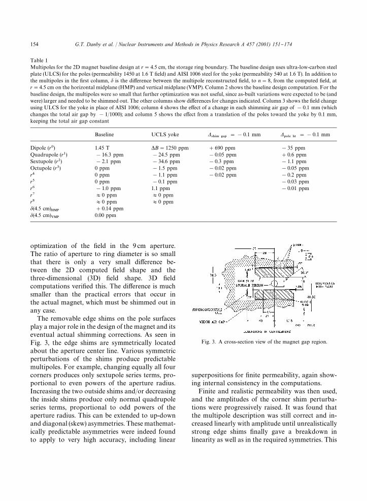
Table 1Multipoles for the 2D magnet baseline design at r"4.5 cm, the storage ring boundary. The baseline design uses ultra-low-carbon steelplate (ULCS) for the poles (permeability 1450 at 1.6 T "eld) and AISI 1006 steel for the yoke (permeability 540 at 1.6 T). In addition tothe multipoles in the "rst column, d is the di!erence between the multipole reconstructed "eld, to n"8, from the computed "eld, atr"4.5 cm on the horizontal midplane (HMP) and vertical midplane (VMP). Column 2 shows the baseline design computation. For thebaseline design, the multipoles were so small that further optimization was not useful, since as-built variations were expected to be (andwere) larger and needed to be shimmed out. The other columns show di!erences for changes indicated. Column 3 shows the "eld changeusing ULCS for the yoke in place of AISI 1006; column 4 shows the e!ect of a change in each shimming air gap of !0.1 mm (whichchanges the total air gap by !1/1000); and column 5 shows the e!ect from a translation of the poles toward the yoke by 0.1 mm,keeping the total air gap constant
Baseline UCLS yoke D4)*. '!1
"!0.1 mm D10-% )5
"!0.1 mm
Dipole (r0) 1.45 T *B"1250 ppm #690 ppm !35 ppmQuadrupole (r1) !16.3 ppm !24.5 ppm !0.05 ppm #0.6 ppmSextupole (r2) !2.1 ppm !34.6 ppm !0.3 ppm !1.1 ppmOctupole (r3) 0 ppm !1.5 ppm !0.02 ppm !0.05 ppmr4 0 ppm !1.1 ppm !0.02 ppm !0.2 ppmr5 0 ppm !0.1 ppm !0.03 ppmr6 !1.0 ppm 1.1 ppm !0.01 ppmr7 +0 ppm +0 ppmr8 +0 ppm +0 ppmd(4.5 cm)
HMP#0.14 ppm
d(4.5 cm)VMP
0.00 ppm
Fig. 3. A cross-section view of the magnet gap region.
optimization of the "eld in the 9 cm aperture.The ratio of aperture to ring diameter is so smallthat there is only a very small di!erence be-tween the 2D computed "eld shape and thethree-dimensional (3D) "eld shape. 3D "eldcomputations veri"ed this. The di!erence is muchsmaller than the practical errors that occur inthe actual magnet, which must be shimmed out inany case.
The removable edge shims on the pole surfacesplay a major role in the design of the magnet and itseventual actual shimming corrections. As seen inFig. 3, the edge shims are symmetrically locatedabout the aperture center line. Various symmetricperturbations of the shims produce predictablemultipoles. For example, changing equally all fourcorners produces only sextupole series terms, pro-portional to even powers of the aperture radius.Increasing the two outside shims and/or decreasingthe inside shims produce only normal quadrupoleseries terms, proportional to odd powers of theaperture radius. This can be extended to up-downand diagonal (skew) asymmetries. These mathemat-ically predictable asymmetries were indeed foundto apply to very high accuracy, including linear
superpositions for "nite permeability, again show-ing internal consistency in the computations.
Finite and realistic permeability was then used,and the amplitudes of the corner shim perturba-tions were progressively raised. It was found thatthe multipole description was still correct and in-creased linearly with amplitude until unrealisticallystrong edge shims "nally gave a breakdown inlinearity as well as in the required symmetries. This
154 G.T. Danby et al. / Nuclear Instruments and Methods in Physics Research A 457 (2001) 151}174

gave con"dence that the computer calculationscould be used to get the design optimization onpaper, and also to calculate multipole perturba-tions of the operating magnet, to correct the "eld toapproaching a 1 ppm level.
Wedge-shaped air gaps between the poles andyoke are an important design feature. These airgaps su$ciently isolate the precision poles from theyoke return that "eld aberations, or multipolesabove the dipole term, are minimally a!ected by rea-sonable variations in the yoke reluctance (Table 1).Since the poles dominate the "eld aberations, thehighest quality of iron is only required for the poles.Very pure continuous cast steel is used for thepoles. This material is typically of 0.004% carboncontent. The higher purity increases permeability atthe operating "eld of the magnet compared to con-ventional AISI 1006 iron (0.07% carbon typically),which is used for the yoke. Even more important isthe impact of the purity on inclusions of ferritic orother extraneous material, air bubbles, etc., whichare greatly minimized.
This isolation of "eld aberations from dipolereluctance has an additional very important prop-erty. It is necessary to have large holes through theyoke to inject the beam, for in#ector power andcryogens, and for the outer coil leads and cooling.Because of the isolation from the air gaps, no signif-icant e!ect on multipoles is observed after restoringthe reluctance in the region of the holes by addinglarge iron collars [5].
The air gaps are wedge-shaped, with a larger airgap on the outer radius, closest to the iron return ofthe C magnet. The slope is calculated to compen-sate for the gradient due to C magnet asymmetry(Fig. 2), where the "eld lines would otherwise tendto cross the gap near the return. Calculationsshowed that a change in wedge angle caused a verypure normal quadrupole adjustment without in-ducing higher multipoles. A change in the wedgeslope by 1 mm over the length of the wedge changesthe quadrupole (at 4.5 cm, the edge of the storagevolume) by 15 ppm, while the sextupole term cha-nges by 1 ppm, and the higher multipole changesare still smaller. Attempting to make a large quad-rupole adjustment by using pole edge shimsintroduces octupole, roughly half the size of thequadrupole change [5]. Instead, a combination of
wedge angle and inside}outside asymmetry in edgeshims can null both quadrupole and octupole.
The inner radius coils, required to be away fromthe midplane to allow observation of decay elec-trons from the stored muons, were pulled still fur-ther vertically away from the midplane in order tohave access to the air gaps for shimming. This hasthe additional advantage of making the hoop forceon these large diameter slender inner coils approx-imately zero.
The "nal coil design used a single layer of theKEK TOPAZ pure aluminum stabilized supercon-ductor [6] to excite the 20 cm air gap. The ironcircuit dominates so strongly that tolerances oncoil location are quite reasonable, as discussedbelow.
Final pole design involved re"nements to theedge shims plus adjustments of the location andangle of the taper of the edges of the poles. To "rstorder, to #atten the "eld, the cross-sectional areaof the edge shims is the important parameter.However, in detail the distance of the inner edge ofthe shims to the center (Fig. 3), chosen to ber"16 cm, and the shim width of r"5 cm, opti-mized the "eld quality by reducing the r6 multipole.This in combination with an edge angle of 36.73produced a very small r2 sextupole, the r4 termwas nulled, and all higher multipole terms werevirtually eliminated.
Making the wedge separate from the poles pre-sented some mechanical complications, but result-ed in substantial shimming advantages. A change inthe air gap, changing the wedge thickness with nochange in angle, produces a very strong e!ect onthe local dipole "eld, essentially proportional to thethickness change divided by the half-gap of 10 cm.This is because the storage ring aperture and airgaps at the base of each pole constitute 93% of thecircuit reluctance. However, small vertical move-ments of the poles have a small e!ect on the reluc-tance, since the combined air gap is unchanged(Table 1).
Errors in the precision pole thickness are smallcompared to the expected variation of up to200 lm in the distance between the top and bottomyoke plate surfaces adjacent to the poles.
A means of shimming in the air gaps is attractive,since only dipole is a!ected, and not higher
G.T. Danby et al. / Nuclear Instruments and Methods in Physics Research A 457 (2001) 151}174 155

Fig. 4. Computed "eld variations for the magnet design.
Fig. 5. Computed magnetic #ux lines for the magnet.
multipoles. The average thickness of the wedgesdetermines dipole, and the wedge angle determinesquadrupole, both essentially pure moments. Fi-nally, if the wedges are radially adjustable, a very"ne control for dipole exists. Since the wedge anglesare approximately 1
50, radial movement by 50 lm
changes the gap by 1 lm, "ner control than isavailable otherwise.
At least on paper, and using realistic parameters,a magnet aperture of 9 cm diameter was designedwith a uniform "eld to a ppm level (Fig. 4).
Long-wavelength `real worlda errors will begreatest for low-order moments, both normal ("eldvertical on the horizontal midplane) and skew. Theshimming techniques described are designed to cor-rect most of these, with surface coils required tocorrect skew dipole.
Correcting coils on the surface of the poles per-mit ultimate "ne control of static, and slowly vary-ing errors. The surface coils can be used to correctlowest multipoles to tens of ppm, thus providingsigni"cant overlap between the iron shimming andthe dynamic shimming. These coils have been con-structed to generate moments over the entire 3603azimuth. The coils were designed with printed cir-cuit boards, with 2]120 wires running azimuthallyaround the ring on the top and bottom pole surfa-ces facing the storage ring gap, and spaced radially2.5 mm apart, to avoid lumpy e!ects which gener-ate higher multipoles. Pole surface corrections canbe (and have been) added with ferromagnetic ma-terial to correct for local e!ects in the iron ge-ometry. Local current loops may also be used. The`continuousa ring was built with 103 pole sections,36 of which form an almost continuous ring. Dipole
correction coils are located in the air gaps for each103 pole.
Strictly speaking, the description of the storagering "eld aberations by multipoles assumes nogradients in the beam direction. However, themuon betatron wavelengths are very long so thatlongitudinal averaging of actual "eld data is correctto a very good approximation. For example, fora 103 pole section the azimuthal integral of "elddata can give an average multipole "t to very goodaccuracy. The pole edge shims or other adjustmentscan be applied to correct this 103 average.
Computations of a 75 lm crack between the 103poles show that the dipole "eld is reduced slightlylocally, but the longitudinal integral was indepen-dent of both r and y, so the e!ect was only on the"eld integral and not on the "eld aberations.
There are limits to averaging out local "eld ir-regularities in the poles, one of which is simply thatthe ability to measure precisely is more di$cultwith large gradients. Thus, the g-2 storage ringshimming e!ort has the goal to make the "eld asuniform as practical.
Fig. 5 shows the magnetic "eld lines for thedesign, and the magnet parameters are given inTable 2.
3. Magnet construction
3.1. Construction of the superconducting coils
The magnet is powered by three superconductingcoils, as shown in Fig. 2. The coil at the outer radiusdrives the "eld across the storage ring gap, and the
156 G.T. Danby et al. / Nuclear Instruments and Methods in Physics Research A 457 (2001) 151}174

Table 2Magnet parameters
Design magnetic "eld 1.451 TDesign current 5200 AEquilibrium orbit radius 7112 mmMuon storage region diameter 90 mmInner coil radius } cold 6677 mmInner coil radius } warm 6705 mmOuter coil radius } cold 7512 mmOuter coil radius } warm 7543 mmNumber of turns 48Cold mass 6.2 metric tonsMagnet self inductance 0.48 HStored energy 6.1 MJHelium-cooled lead resistance 6l)Warm lead resistance 0.1m)Yoke height 157 cmYoke width 139 cmPole width 56 cmIron mass 682 metric tonsNominal gap between poles 18 cm
Table 3Conductor parameters
Superconductor type NbTi/CuNominal dimensions 1.8 mm]3.3 mmNbTi/Cu ratio 1:1Filament 50 lmNumber of "laments 1400Twist pitch 27 mmAluminum stabilizer type Al extrusionNi/Ti composite dimensions 3.6 mm]18 mmAl/(NbTi#Cu) ratio 10RRR (Al) 2000}2500RRR (Cu) 120}140I#
8100 A (2.7 T, 4.2 K)
two coils at the inner radius, above and below themidplane, cancel the #ux in the ring center andimprove the "eld quality in the gap. The outer coilcarries 5200 A with 48 turns. It is split into twoblocks, above and below the midplane, to allow thebeam to enter the storage ring. The inner coils areeach 24 turns, connected in series with the outercoil, with the reverse current direction.
The mechanical design of any superconductingmagnet must provide support for the coils againstthe large Lorentz forces, and at the same time resultin little heat load. The superconducting coilsneeded to be held in a way that would avoidstick}slip conditions when powering the magnetwhich could lead to quenching the magnet. The coillocations needed to repeat to $0.5 mm in radius,to maintain the required "eld quality. The "eld isrelatively insensitive to the coil position. A localradial shift of 1 mm changes the dipole "eld by116ppm, but the muon trajectories in the storagering average over the azimuth, so that the change inaverage dipole "eld due to radial shifts of the coiltends to cancel. Quadrupole, sextupole and oc-tupole terms are changed by less than 0.1 ppm fora 1 mm radial shift. For a vertical shift in outer coilmandrel position, one coil block shifts away fromthe midplane, and one coil block shifts toward the
midplane, which cancels the e!ect on the "eld to"rst order, leaving less than 1 ppm dipole change,and less than 0.1 ppm change for higher multipolesfor a 1 mm shift. The e!ect of shifts of the inner coilsis smaller yet [5].
The large coil diameter and small height present-ed both design and construction concerns. Thecoils easily deform elastically in the radial direction,and also vertically. Furthermore, the coils shrink30 mm in radius during cooldown, and the outercoil then expands in radius 3 mm when powered.These made the design of a coil support and locat-ing system di$cult.
The coil design was based on the TOPAZ sol-enoid at KEK [6]. TOPAZ conductor was used,with pure aluminum stabilizer and niobium}tita-nium superconductor in a copper matrix. Conduc-tor characteristics are given in Table 3. At full "eldthe critical temperature of the outer coil is 6.0 K.The magnet typically operates at 5.0 K. This repres-ents 76% of the superconductor limit. Each coilblock is e!ectively a very short solenoid with 24turns, and one layer. The coils are wound from theinside of the ring so that, when powered, the coilspush out radially against a massive aluminum man-drel. Cooling is indirect with helium pipes attachedto the mandrels. The coil turns, coil stack andinsulation are epoxied together, forming a mono-lithic block. The coils hang from the cryostat withlow heat load straps, and the shrinkage and expan-sion of the coils is taken by the straps. The coils arelocated using radial stops on the inner radius. Forthe outer coil the stops transfer the force from the
G.T. Danby et al. / Nuclear Instruments and Methods in Physics Research A 457 (2001) 151}174 157

Fig. 6. The completed outer coil and cryostat were passedthrough the slot in the g-2 building and stored outside, inpreparation for construction of the lower half of the magnetyoke. The completed inner coils in their cryostats are in theforeground.
Fig. 7. The coil winding "xture, shown on the turntable. Aninner coil is being wound.
Fig. 8. A cross-section of the outer coil and cryostat assembly atthe location of a radial stop.
coil to the cryostat box, and push rods fromthe iron yoke transfer the force from the box to theiron. For the inner coils, pins replace the pushrods.
3.1.1. Mandrel construction and coil windingThe coils were built in the g-2 experimental
building with a #oor area only somewhat largerthan the ring. The coils were constructed in se-quence: each of the three coils was wound andtransported outside for temporary storage, fol-lowed by construction of each cryostat/coil assem-bly. These assemblies were stored outside duringconstruction of the bottom half of the iron yoke.The transfers were done using a "xture which sup-ported the coil circumference, and interior and ex-terior cranes. The "xture included wheels whichrolled on tracks to pass the coil through a slot builtinto the side of the building (Fig. 6). Coil construction was based on a large turntable
with a 2.4 m radius, rated for a 36 metric tonnon-eccentric loading (Fig. 7). It was powered bya 15 hp motor with a drive ranging from 0.005 to0.3 revolutions per minute. An additional platformextended the working radius to 6.7 m for the innercoils and 7.5 m for the outer radius coils. A tracksupported the outer end of the platform, with a0.5 mm vertical runout maximum. The turntablesupported a milling machine and the coil winder.The construction of the outer coil is described here,with signi"cant di!erences in inner coil construc-tion noted.
The aluminum mandrel (Fig. 8) supports com-pressive conductor preload, it supports the coil
158 G.T. Danby et al. / Nuclear Instruments and Methods in Physics Research A 457 (2001) 151}174

against the Lorentz force, and it indirectly cools thesuperconductor via liquid helium carried in tubeswelded to the mandrel outer radius. The mandrelcross-section includes an inner radius ledge for eachcoil block. The outer mandrel cross-section waschosen to limit expansion under Lorentz force to3 mm radius. The mandrel was built from 12 sec-tions, which were rolled to shape, "nish machinedon outer radius and bottom, and rough machinedon inner radius and top. The bending process pro-ved di$cult, due to the asymmetry from the ledges.Machining, bending, heat treating to remove stres-ses, and rebending were necessary. An independentledge piece, attached to the mandrel, may havebeen a better approach. The 12 sections were thenjoined with full penetration welds of the 50 mmthick outer mandrel, using a massive weld "xtureand a combination of MIG and TIG welds. Peen-ing of the weld joint between each welding passwhile hot was essential to minimize distortion. Themilling machine on the turntable was used to com-plete the inner winding surface and mandrel top.
In the next step, the rectangular tubes for theliquid helium were stitch-welded to the mandrel,using alternate welds 2.5 cm long, above and belowthe tube and leak tested. Leak testing was parti-cularly important because the coils are inaccessible.The tubes were cycled to liquid nitrogen temper-ature twice, warming to room temperature in be-tween. A vacuum leak check was performed wherethe tube was evacuated and helium was sprayedonto every joint from the outside. The last step wasto pressurize the tube to 250 psi with helium gas,and to check each joint by bagging each region for10 min, then sni$ng the bag.
At this point, the mandrel was prepared forwinding. A ground plane insulation band of 0.3 mmthickness was built from a sandwich of three layersof 50 lm kapton, epoxy coated, between two layersof epoxy-"lled "berglass. The insulation assemblywas fully cured and placed into the mandrel. A 0.1mm layer of B-stage epoxy "lm was placed betweenthe mandrel and kapton laminate, and between thekapton laminate and the conductor block afterwinding. A 4.8 mm thick G-10 piece was placed onthe winding ledge, and on top and on the innerradius of the completed coil block. The insulationprotected against a local failure in an insulation
layer and against creep failure along a surface. Theepoxy-"lled "berglass in the ground plane insula-tion sandwich improved heat transfer between coiland mandrel.
The coil winder was then installed on the turnt-able, as shown in Fig. 7. This device includeda single conductor width spool with 1 km of con-ductor, a caterpillar drive which applied 625 N ofcompressive force to the conductor, a 3-head insu-lation-wrapping machine, the insulation test stand,and guides which bent the wide dimension of theconductor to a 1.5 m radius, approaching the man-drel at a 103 downward angle. A last guide reshapedthe conductor to the nominal radius and supportedthe conductor into the mandrel. The conductorfeed device automatically adjusted the height foreach of the 24 layers. A 1.4 m long G-10 ramp at theend of the "rst layer provided a spiral wind to thesecond layer. Long sections of conductor were leftat both ends of the wind to form the leads toconnect in series with the other coils and to the coldto warm transition or lead pot.
Turn-to-turn insulation used three overlappinglayers of kapton (25 lm each) and "berglass "lledwith B-stage epoxy, 19 mm in width. Layerswere helically wrapped around the conductor with0}0.8 mm between turns; each of the three layerswere o!set by 6.4 mm. This wrap was applied andtested at 2000 V DC during the wind.
The winder typically ran at 0.6 m/min. Duringthe operation, closely spaced pneumatic verticalclamps automatically extended to press on the topsurface of the conductor to preclude buckling asthe conductor was pushed against the mandrel. Themethod of winding, applying the conductor to theinside of a mandrel, results in the mandrel absorb-ing the outward Lorentz force of the coil.
After the 24th layer, the conductor was shapedaway from the coil block to be used as a lead.Aluminum covers were then added in 90 cm sec-tions, including top and inner radius insulation asmentioned. The covers restrain the coil radially andvertically, and act as a heat shield to isolate thecoils. Electrical strip heaters, attached temporarilyto the mandrel and covers along with an outerwrap of "berglass insulation, were used to cure theepoxy. Spring-loaded clamps compressed thecovers during the cure. A temperature of 1253C was
G.T. Danby et al. / Nuclear Instruments and Methods in Physics Research A 457 (2001) 151}174 159

Fig. 9. An inner coil assembly cross-section.
used for 1 h. For the outer coil, each block waswound and cured separately, so that the lower coilblock received two heating cycles. This procedurehad been found in tests to be acceptable for theepoxy and the temperature is well below 4003Cwhere superconductor deteriorates. Extensive testsdeveloped the correct amount of epoxy needed tocompletely "ll the coil blocks without voids.
The spring clamps assured that the covers wereforced to their "nal position for bolting, so as toapply both a vertical prestress to enhance heat con-duction between conductor layers, and a radiallyoutward prestress of the coil block into the man-drel. This radial preload of 1.8}2.2]104 N/m cir-cumference was used to assure no local coil motionduring powering, where the Lorentz force is7]104 N/m outward for the two outer coil blockstogether and 1]103 N/m inward for the innercoils at full "eld.
3.1.2. Cryostat assemblyThe coil cryostats provide the insulating vacuum,
coil suspension and positioning, heat shields andsuperinsulation, and cooling and electrical connec-tions. The cryostat box must allow for the 30 mmradial shrinkage of the coil from cooldown, withrepeatable coil positioning.
An insulating vacuum of 10~5 Torr was required.All welded construction was used. The boxes wereconstructed using 6061 T-6 aluminum alloy plate.Inner coil cryostat walls are 1.2 cm thick; outer coilcryostat side walls are 1.9 cm thick, and top andbottom walls are 1.6 cm thick. U-sections wereformed in azimuthal sectors (16 sectors outer, 12sectors inner) and welded to form an open box ina continuous circle.
At this stage, the coil was brought back into thebuilding and suspended above the open cryostat.Fig. 8 shows the components in an outer coil cryos-tat assembly. Hangers were attached to the coil.Blankets of superinsulation were wrapped aroundthe coil, the heat shield built in place, and addi-tional superinsultation added. The coil was thenlowered into the cryostat, the straps attached to thecryostat, and the cryostat covers were welded on.
The hanging straps [7] are racetrack shaped,2 cm wide, 26 cm long, and 2.5 cm across. Theywere built at Brookhaven from multi"lament "ber-
glass and B-stage epoxy. The straps have hightensile strength (1]109 Pa) and low thermal con-ductivity. The heat leak for one strap is calculatedto be 0.14 W. For the outer coil and upper innercoil, side plates were added for compressivestrength: the outer coil vertical force is unstableabout the midplane, and the upper inner coil verti-cal force is upward, opposite gravity. The suspen-sion arrangements were di!erent for the outer andinner coils. For the outer coil, one strap was used tohang the coil from the outer radius of the cryostatbox, at 16 azimuthal locations. This is shown inFig. 8. At room temperature, the outer coil hangswith the straps vertical. When cooled, the coilshrinks 30 mm in radius and the coil rises 3.3 mm.When powered, the outer coil expands 3 mm inradius, and the nominal hanger angle is 103 inwardfrom vertical. The vertical Lorentz force is unstable,5]102 N/m in circumference per mm vertical dis-placement away from the midplane. The outer coilcenter was originally placed to be 0.5 mm below themidplane powered. The "nal o!set, done after wefound that some of the coil rose above the midplaneduring initial magnet testing, was 1.5 mm below themidplane powered.
The inner coils hang from pairs of straps at 48azimuthal locations. The strap angles, when pow-ered, are vertical, Fig. 9. For this geometry, a radialmisalignment, either inward or outward, leads toa vertical displacement and a strong vertical restor-ing force. The vertical Lorentz force gradient for theinner coils is 2]103 N/m in circumference per mmvertical displacement away from the midplane. Theradial force gradient is 1]102 N/m per mm out-ward for an outward displacement.
160 G.T. Danby et al. / Nuclear Instruments and Methods in Physics Research A 457 (2001) 151}174
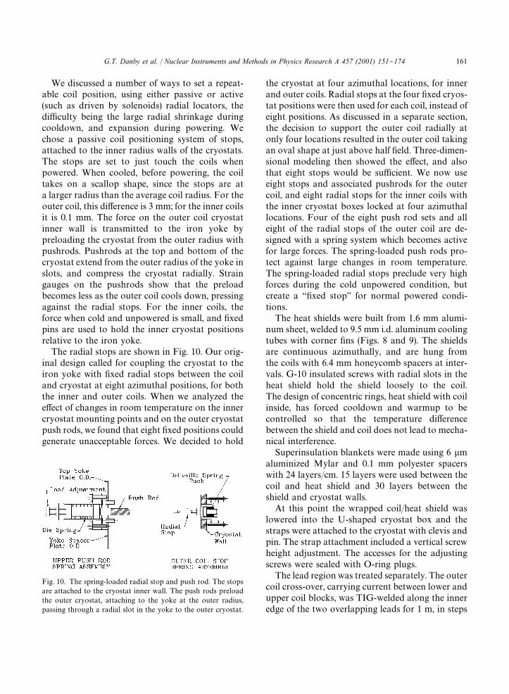
Fig. 10. The spring-loaded radial stop and push rod. The stopsare attached to the cryostat inner wall. The push rods preloadthe outer cryostat, attaching to the yoke at the outer radius,passing through a radial slot in the yoke to the outer cryostat.
We discussed a number of ways to set a repeat-able coil position, using either passive or active(such as driven by solenoids) radial locators, thedi$culty being the large radial shrinkage duringcooldown, and expansion during powering. Wechose a passive coil positioning system of stops,attached to the inner radius walls of the cryostats.The stops are set to just touch the coils whenpowered. When cooled, before powering, the coiltakes on a scallop shape, since the stops are ata larger radius than the average coil radius. For theouter coil, this di!erence is 3 mm; for the inner coilsit is 0.1 mm. The force on the outer coil cryostatinner wall is transmitted to the iron yoke bypreloading the cryostat from the outer radius withpushrods. Pushrods at the top and bottom of thecryostat extend from the outer radius of the yoke inslots, and compress the cryostat radially. Straingauges on the pushrods show that the preloadbecomes less as the outer coil cools down, pressingagainst the radial stops. For the inner coils, theforce when cold and unpowered is small, and "xedpins are used to hold the inner cryostat positionsrelative to the iron yoke.
The radial stops are shown in Fig. 10. Our orig-inal design called for coupling the cryostat to theiron yoke with "xed radial stops between the coiland cryostat at eight azimuthal positions, for boththe inner and outer coils. When we analyzed thee!ect of changes in room temperature on the innercryostat mounting points and on the outer cryostatpush rods, we found that eight "xed positions couldgenerate unacceptable forces. We decided to hold
the cryostat at four azimuthal locations, for innerand outer coils. Radial stops at the four "xed cryos-tat positions were then used for each coil, instead ofeight positions. As discussed in a separate section,the decision to support the outer coil radially atonly four locations resulted in the outer coil takingan oval shape at just above half "eld. Three-dimen-sional modeling then showed the e!ect, and alsothat eight stops would be su$cient. We now useeight stops and associated pushrods for the outercoil, and eight radial stops for the inner coils withthe inner cryostat boxes locked at four azimuthallocations. Four of the eight push rod sets and alleight of the radial stops of the outer coil are de-signed with a spring system which becomes activefor large forces. The spring-loaded push rods pro-tect against large changes in room temperature.The spring-loaded radial stops preclude very highforces during the cold unpowered condition, butcreate a `"xed stopa for normal powered condi-tions.
The heat shields were built from 1.6 mm alumi-num sheet, welded to 9.5 mm i.d. aluminum coolingtubes with corner "ns (Figs. 8 and 9). The shieldsare continuous azimuthally, and are hung fromthe coils with 6.4 mm honeycomb spacers at inter-vals. G-10 insulated screws with radial slots in theheat shield hold the shield loosely to the coil.The design of concentric rings, heat shield with coilinside, has forced cooldown and warmup to becontrolled so that the temperature di!erencebetween the shield and coil does not lead to mecha-nical interference.
Superinsulation blankets were made using 6 lmaluminized Mylar and 0.1 mm polyester spacerswith 24 layers/cm. 15 layers were used between thecoil and heat shield and 30 layers between theshield and cryostat walls.
At this point the wrapped coil/heat shield waslowered into the U-shaped cryostat box and thestraps were attached to the cryostat with clevis andpin. The strap attachment included a vertical screwheight adjustment. The accesses for the adjustingscrews were sealed with O-ring plugs.
The lead region was treated separately. The outercoil cross-over, carrying current between lower andupper coil blocks, was TIG-welded along the inneredge of the two overlapping leads for 1 m, in steps
G.T. Danby et al. / Nuclear Instruments and Methods in Physics Research A 457 (2001) 151}174 161

of 8 cm in 10 s. In addition, a helium cooling tubewas TIG-welded on the inner edge to the conductorover this distance. Only 20}30 cm at each end isuncooled. The leads to and from the outer coil weretaken from above and below the upper and innercoil blocks respectively, and were brought togetheron the midplane separated by 240 lm kapton andthe insulation wrapped around the leads (230 lm).The pair was then passed radially through an ac-cess hole in the mandrel to the outside radius. Theradial sections of the leads are also cooled overtheir length, with 30 cm uncooled at the coil blocks,and form a radial pair in the transfer line. Coolingtubes were welded above and below the pair in thetransfer line. The heat shield was enlarged to theinner radius in this region, as was the cryostat boxto accomodate the lead support assembly. Conduc-tor heating from the welding operations wasmodeled, giving a maximum temperature of 3503C.Degradation of niobium}titanium critical currentof 5% was measured for 2 T magnetic "eld for anannealing time of 10 s for 4003C [8]. A test overlapjoint showed a resistance of 16]10~9 ) at2 T "eld.
The outer coil was cooled down, before complet-ing the magnet, to test the cooling scheme. This wassuccessful, but a port with O-ring for the inner wallof the outer cryostat was added for access to thiscritical area. Additionally the heat shield was im-proved at this time and temperature sensors wereincluded in the uncooled lead region where theconductors are routed radially out of the coil. The#ow arrangement for the liquid nitrogen in the heatshield was modi"ed to be parallel for the two tubes,with the #ow making one complete turn in azi-muth, to improve cooldown time. The #ow forhelium for the outer mandrel is around the azimuthin one direction, crossing to the second tube, thenreturning in the other direction. The mandrel isthermally continuous around the azimuth, so thatthe warm location during cooldown is 180" fromthe lead region. The heat shield was thermally andelectrically separated by a G-10 piece at the leadarea, primarily to reduce eddy currents in the heatshield. For the inner coils, the heat shields areelectrically and thermally continuous around theazimuth, and both the nitrogen and helium linesmake one azimuthal loop.
3.1.3. Cryogenic transfer linesThe transfer lines were built to allow for the
radial changes from cooldown, using a large bendradius for the inner coil conductors which arebrought radially above and below the magnet tojunction boxes on the magnet outer radius, andusing a large hairpin loop for the outer coil conduc-tors. Helium cooling tubes were welded to the con-ductors over the entire length of the transfer lines,and liquid nitrogen heat shields were used over thelength. The helium cooling tubes were electricallyisolated in the transfer lines.
3.2. Yoke and pole construction
3.2.1. YokeThe magnet is constructed with 12 303 sectors, to
limit the size and weight of the individual parts forease of fabrication and assembly. Each sector,Fig. 2, is built up of steel plate and consists of anupper and lower yoke separated by a spacer plate.The sector weight is about 57,000 kg, including endsupports and additional parts, and the completemagnet weighs approximately 680 metric tons.
It is di$cult to "nd suppliers of quality steel whocan roll plate steel to the thickness required for theupper and lower yoke plates. To allow the max-imum number of steel suppliers to bid, and toreduce the chances of voids through reduction inthickness during the hot-rolling process, these com-ponents have been supplied as two separate plates.The plates were welded together at the interfaceduring the machining step. The spacer plate is alsomade in two pieces to facilitate installation of beampipes, transfer lines and electrical connections tothe outer coil cryostat.
The upper and lower yoke plates and spacerplates are held in place by eight high-strength steelbolts per sector, extending through all of the platesvertically. These bolts are 5 cm in diameter andwere tensioned to 80,000 kg each, which is 57% ofthe yield point. In addition, the three assemblies,the upper yoke plate, spacer plate and lower yokeplate are doweled together to allow ease of disas-sembly and reassembly while maintaining theirhorizontal relationship.
A feature of the overall magnetic design is tohave the yoke continuous azimuthally. To achieve
162 G.T. Danby et al. / Nuclear Instruments and Methods in Physics Research A 457 (2001) 151}174

this, each sector end has four radial projections forbolts to fasten adjacent sector ends to each other.When the sectors are "tted to each other, shimmed,and the bolts tightened, relative motion of adjacentsectors is minimized.
Rolled steel plates are speci"ed for the majorpieces of steel used in the yoke plates and spacerplates. These have 0.08% carbon maximum witha minimum of alloying elements and impurities. Allrolled plates have been completely inspected ultra-sonically for voids and the composition of eachplate has been determined by chemical analysis.The background information of each piece wasretained by a numbering system stamped into thesteel pieces.
The lower horizontal face of the upper yoke plateand the upper horizontal face of the lower yokeplate were milled #at within 130lm and 1.6 lm"nish. The inner radius of each yoke plate machin-ing tolerance was to within $130 lm of the basicdimension.
Upper and lower surfaces of the spacer platewere milled #at within$130 lm and parallel within180 lm, and thickness accurate to $130 lm. Bothinner and outer radii of the spacer plate toleranceswere within $130 lm of the true radius. The as-built vertical yoke gap has an rms deviation of$90 lm, or 500 ppm of the total air gap of 20 cm,and a full-width spread of $200 lm.
Aximuthal machining requirements were that thesector ends be perpendicular to the gap faces towithin $0.3 mrad and that the ends be radial towithin $0.2 mrad. The chords between the outerradius corners of the as-machined sectors have anrms deviation of $0.25 mm and a mean of !0.03mm. The design azimuthal gap between sectors was0.5 mm. The as-built azimuthal gaps for the loweryoke average 0.8 mm, with an rms deviation of$0.2 mm. Spacer plates and upper sectors werematched to the lower sectors to equalize the e!ec-tive azimuthal gap for the three pieces, weighted bythe magnetic reluctance for each sector.
3.2.2. Poles and wedgesThe pole pieces are shown in Fig. 2. The poles
directly a!ect the "eld quality, while the e!ect ofyoke imperfections is minimized by the air gapsbetween the yoke and poles. The poles require
high-quality steel, with tight machining toleranceson the #atness of the faces which de"ne the storagering gap. The pole steel was continuous vacuum-cast with 0.004% carbon. The tolerance on #atnesswas 25 lm, which represents 140 ppm of the stor-age gap. The surface was ground to a 0.8 lm "nish(4 ppm). The pole widths were machined to56$0.005 cm, and the thickness to 13.3$0.004cm. The upper and lower faces were machinedparallel to 0.005 cm.
In order to control and adjust the pole locationand tilt, the poles were constructed in 103 azi-muthal sections, compared to the 303 sectors of theyoke. The pole edges that align with the yoke sec-tors were machined radial, and the middle pole ofeach sector is interlocking, with a 73 angle fromradial. The poles were located azimuthally with80 lm kapton shims, with the pole edge each 603 inazimuth machined to the correct azimuth. Thenkapton was used to electrically isolate the polesfrom each other to control eddy current e!ects from"eld changes, from ramping or quench.
The pole edge-shims were built oversized(4.4 mm thick for the shims on the i.d.; 3.2 mm thickfor the o.d. shims) to allow for perturbation adjust-ment during the magnetic "eld shimming. The shimwidth is 5.0 cm. The edge shims are attached to thepoles using #athead iron screws, countersunk intothe shims every 12 cm in azimuth. This spacingadequately holds the shims from the unstable mag-netic force which attempts to short the gap.
The poles are attached to the yoke plates by steelbolts whose heads are counter-bored deeply intothe poles (see Fig. 2). The bolts are located in thetapered region of the poles away from the storageregion, and the bolt heads are covered by cylin-drical plugs of pole steel.
The as-built storage ring gap with a design valueof 18 cm was measured using capacitance devices to$1 lm accuracy. The gap height varied by$23 lm rms with a full range of 130 lm. The tiltsof the poles in the radial direction were measuredwith a precise bubble level and adjusted to$50 lrad. The poles were aligned to be horizontalwhen powered. This required an initial openingangle of 80 lrad toward the ring center to compen-sate for the asymmetric closing of the gap, as shownin Fig. 11. Adjacent poles were matched to
G.T. Danby et al. / Nuclear Instruments and Methods in Physics Research A 457 (2001) 151}174 163

Fig. 11. The measurement of the storage ring gap as a functionof magnet current, using the capacitance device described in thetext. The gap was measured at r"#15 cm (a), andr"!15 cm (b), relative to the center of the storage region. Thegap values at full "eld, 5200 A, have been subtracted. The totalgap closure as well as the di!erence (a)}(b)"(c) is in goodagreement with stress calculations.
Fig. 12. The measured and calculated torque on a pole duringramp-up, with the pole pivoting about the inner radius spacers.At lower current, the outer radius of the pole tries to short thegap, pulling away from the yoke. The torque at full current, 5200A, is the opposite sign, with the pole pushing against the spacerstoward the yoke.
$10 lm to keep "eld distortions caused by stepsin the iron surface small.
The shimming gaps between the yoke and polesserve three purposes: the gaps decouple the yokesteel from the poles; #at dipole correction coils foreach pole are installed in the gaps to adjust thedipole "eld in azimuth; and the gaps contain ironwedges used to shim the magnetic "eld. Thewedges, sloped radially to provide the C-magnetquadrupole correction, are attached so that theycan be adjusted radially. The radial adjustmentchanges the dipole "eld locally. The wedges are 9.86cm wide (azimuthal direction), with 72 per 303sector. They are 1.65 cm thick on the inner radius,0.5 cm thick on the outer radius, and are 53 cm long(radial direction). Note that the wedges are rectan-gular in the r}/ plane, so that there is a larger gapazimuthally between the wedges on the outerradius.
A di$culty that we did not anticipate was thatthe magnetic force direction was quite di!erent at
lower "eld than for full "eld. The wedge angle isdesigned to distribute the "eld lines uniformlyradially at full "eld, with the yoke and wedge ironpartly saturated. At lower "eld, however, the iron isnot saturated, and the smaller total gap at thelarger radius, where the wedges are thicker, drawsmore "eld lines. This leads to a torque on the polesand wedges. To stabilize the wedges, clamps weremade from aluminum sheets taped together withthe appropriate `anti-wedgea shape. The poles areheld in place by the bolts described above, andaluminum/steel laminated spacers are used to holdthe poles away from the yokes. At full power theforce is 2]106 N per pole. The iron lamination inthe spacers replaces iron in the wedges that arenotched, due to the spacers. There are 24 spacersfor each 303 sector, located at the sector ends and at2.53 azimuthal intervals, on the inner and outerradii of the poles. We measured the torque on apole during ramp-up (Fig. 12) and con"rmed calcu-lations that the pole attachments were su$cient.
3.2.3. Magnet supportThe magnet is intended to move as a single rigid
body, as much as possible. The magnet supportsare located at the 12 sector joints, and are designedto move the sector pairs together. The ring also sitson low-friction pads, and is held to the #oor at onlyone azimuthal position.
164 G.T. Danby et al. / Nuclear Instruments and Methods in Physics Research A 457 (2001) 151}174

Table 4Power supply parameters
Rating 5 V, 6500 A
Recti"er 480 VAC input,12 pulse(Two $153, 6 pulseunits in parallel)
Output "lter 0.4 F
Regulator Low-level system 0.1 ppm stabilitywith 17 bitresolution
Power section Series regulatorwith 504 passtransistors
Cooling Closed loop watersystemwith temperatureregulation
Regulation Current}internalDCCT
$0.3 ppm overminutes toseveral hours
Field}NMRfeedback
$0.1 ppm(limited by the
(current vernier) electronics noise#oor)
Manufacturer Bruker, Germany
At the contiguous ends of each sector there is acommon base plate of 7.6 cm thick steel. These baseplates are solidly bolted and grouted to the #oor.
On the top of each baseplate are four 25 ton Du!Norton worm gear screw jacks. These are locatedto act at the inner and outer radius of the ends ofadjacent sectors. The top of each jack has a platewith a low-friction facing to allow the magnet sec-tor to be adjusted radially. The actuating shafts ofthe jacks at the inner and outer radii are alignedwith each other so that after the sectors were posi-tioned the jacks were coupled together. When verti-cal adjustment is necessary the rotation of oneactuating shaft adjusts the vertical sectors togetherto the proper vertical position without changingtheir relative positions. Also on the base plate aremassive angle brackets with adjusting screws tomove the sector ends radially.
To cope with possible horizontal motion of the#oor, the four large bolting lugs on the lower andupper yoke assemblies have ground shims placedbetween the adjacent sectors so that, when the 5 cmbolts in each set of lugs are tensioned, the g-2magnet yoke acts as a unit and slides on the anti-friction pads on top of the jacks. The radial re-straint from the brackets on the base plates hasbeen relaxed except for one location. Computercalculations based on the sti!ness of the magnetyoke, measured #oor motion, and the friction fromthe sliding pads have shown that the magnet ring ise!ectively decoupled from the #oor motion by thissystem.
4. Power, protection and cryogenics
4.1. Power supply
Both persistent mode and power supply excita-tion were considered. The total #ux, :B ) dS, isconserved in persistent mode. However, room tem-perature changes would result in changes in thee!ective area. Thus although the #ux is conserved,the magnetic "eld in the muon storage region is not.Persistent mode would also require a high-currentsuperconducting switch. Power supply excitationwith NMR feedback was chosen, although no feed-back was used for the 1997 run. This method gives
excellent control of the magnetic "eld and allowsthe magnet to be turned o! and on easily. Thepower supply parameters are shown in Table 4.
4.2. Quench protection
The quench protection design parameters weredetermined by the requirements of magnetic "eldstability and protection of the magnet system incase of a quench. When the energy is extracted,eddy currents are set up in the iron which opposethe collapse of the "eld. This can cause a permanentchange in the magnetic "eld distribution [9]. This issometimes called the `umbrellaa e!ect, since theshape of the change over a pole resembles an um-brella. The eddy currents are minimized if the en-ergy is extracted slowly. There will also be eddycurrents in the aluminum mandrels supporting thecoils. Electrically, this can be represented by a one
G.T. Danby et al. / Nuclear Instruments and Methods in Physics Research A 457 (2001) 151}174 165

Fig. 13. Diagram of the quench protection circuit.
Table 5Estimates of cryogenic heat leaks
4.9 Kload(W)
80 Kload(W)
Magnet system Outer coil cryostat 52 72heat load Two inner coils 108 77
In#ector 8 5Interconnects 11 46Magnet subtotal 179 200
Distribution Helium piping 19Control dewar 5Interconnects/valves 33 32Nitrogen piping 34Distribution subtotal 57 66
Lead gas (1.1 g/s) Equivalent refrigeration 114
Total refrigeration 351 266Contingency 70 51Cryogenic design Operating point 421 308
turn shorted transformer. These eddy currents willheat the mandrels and can cause the entire coil tobecome normal. This is called quench-back. Thishas several bene"cial e!ects. The part of the storedenergy that is deposited in the coil is depositeduniformly over the entire coil and mandrel assem-bly. Also, once quench-back occurs, the energyextraction process is dominated by the quench-back and not by the speci"cs of where the quenchoccurred. Therefore, the e!ects of a quench on thereproducablility of the magnetic "eld should beminimal.
The energy extraction system consists of aswitch, resistor, and quench detection electronics.An energy extraction resistor of 8 m) was chosen.Including the resistor leads, the room temperatureresistance is 8.8 m). This gives an ¸/R time con-stant of 1 min. The actual time constant varies dueto the temperature increase of the coil and dumpresistor and the e!ect of eddy currents in the man-drels during the energy extraction (see below). Thisresistance value was calculated to cause quench-back in the outer mandrel within 2 s at full current.
The quench protection circuit is shown inFig. 13. The energy extraction trigger for a quenchwhich originates in one of the coils is the voltagedi!erence between matching coils; for example,<(outer-upper) !<(outer-lower). Since the induc-tance is e!ectively the same, the voltages should beequal even while charging the magnet, unlessa quench develops in one coil. This quench thresh-old is set at 0.1 V. However, the coil interconnectsare thermally coupled together with the heliumtubes. It is possible that a quench in an interconnectcould propagate to both coils almost simulta-
neously. Therefore, a voltage threshold of 10 mVwas chosen for each interconnect. The outer upperto lower interconnect is only 1 m long. Thisthreshold was set to 5 mV. The thresholds weredetermined by the requirement that the quench bedetected within 0.2 s. The gas-cooled leads developa voltage of typically 15 mV at full current. If thelead voltage exceeds 30 mV, the energy is extracted.
4.3. Cryogenics system
The storage ring magnet is cooled with two-phase helium #owing through tubes attached to thecoil mandrels, to the superconducting coil electricalinterconnects, and to the in#ector coil package. Thesuperconducting coils are cooled by conductionfrom the mandrels. The in#ector [10] is a supercon-ducting magnet which cancels the "eld seen by theincoming beam. It will be the subject of a futurepaper. The #ow of two-phase helium is provided bythe Joule}Thomson (J}T) circuit of a helium refrig-eration plant located in a building near the experi-ment. The 80 K shields around the coils are cooledwith pressurized liquid nitrogen delivered froma liquid nitrogen storage tank. The heat leaks at4.9 and 80 K into the magnet cryogenic system aregiven in Table 5.
166 G.T. Danby et al. / Nuclear Instruments and Methods in Physics Research A 457 (2001) 151}174

The helium refrigerator uses a modi"ed Claudecycle with liquid nitrogen precooling. With nitro-gen precooling, the refrigerator produces 625 W ofcooling at 4.9 K, when it is supplied with 100 g/sof helium at a pressure of 1.8 MPa from a pair ofscrew compressors. Helium makeup and recoveryoccurs at the compressor end of the helium system.
The two-phase helium cooling avoids the in-crease in temperature that would occur in a circuitcooled with single-phase helium. The operatingtemperature of the coils is within 0.2 K of thecoldest temperature in the cooling circuit. The ad-vantages of two-phase cooling are: (1) the helium#ows in well-de"ned #ow circuits; (2) the totalamount of helium that can be #ashed o! duringa quench is limited to the mass of helium in themagnet cooling tubes; and (3) the location ofthe helium input and output from the cryostat andthe location and orientation of the gas cooled leadsare not a!ected by the cooling system [11].
The key to the operation of a two-phase heliumcooling circuit is a helium dewar (the control dew-ar) that contains a heat exchanger. This heat ex-changer sub-cools the helium from the J}T circuitbefore it enters the magnet cooling circuits. Thisisobaric cooling provides a higher ratio of liquid togas with a higher pressure and lower temperaturethan the refrigerator J}T circuit alone would pro-vide. This feature is important for the long coolingchannels in the magnet cooling circuits. The use ofa heat exchanger in the control dewar reduces thehelium #ow circuit pressure drop by a factor of twoor more. The control dewar and heat exchangeralso have the e!ect of damping out the oscillationsoften found in two-phase #ow circuits. The heliumin the control dewar acts as a bu!er providingadditional cooling during times when the heat loadexceeds the capacity of the refrigerator.
The g-2 cooling system was originally designedto have three separate cooling circuits [12]: a 218 mlong cooling circuit that cools all three mandrels inseries, the lead and coil interconnect circuits thatare 32 m long (the gas-cooled leads are fed o! ofthis circuit), and a 14 m long cooling circuit for thein#ector magnet. Later the cooling system wasmodi"ed to permit each of the mandrels to becooled separately. Ultimately, the g-2 cooling sys-tem operates with parallel cooling circuits for the
coils, in#ector, and lead cooling. Electrically, thethree coils are connected in series so that the twoinner coils are in opposition to the outer coil toproduce a dipole "eld between the inner and outercoils. The magnet is powered through a pair oftubular gas-cooled leads developed for this applica-tion. Each lead consists of a bundle of "ve tubes[13,14]. Each tube in the bundle consists of threenested copper tubes with helium #ow betweenthe tubes. The copper tubes used in the leads aremade from an alloy with a residual resistance ratioof about 64. The lead length is 500 mm. A typicalcool down from 300 to 4.9 K takes about 10 d.Once the control dewar starts to accumulate liquidhelium, it takes another day to "ll the 1000 l dewar.
In operation, the pressure drop [15] across themagnet system is about 0.02 MPa (3.0 psi). Weinitiated several test quenches and had one unin-tentional quench when the cooling water was shuto! to the compressors. The peak measured pressureduring a 5200 A quench was 0.82 MPa (105 psig).Other places in the cooling circuit could havea pressure that is 40% higher. The quench pressurepeak occurs 11 s after the start of the quench.The quench pressure pulse is about 12 s long com-pared to current discharge time constant at 5200A of 31 s. The outer coil mandrel temperaturereaches 38 K after the quench is over. Recooling ofthe magnet can commence within 5 min of the startof the quench. After a full current quench, it takesabout 2 h for the outer coil to become completelysuperconducting. The inner coils recover morequickly.
5. Magnet operation
5.1. Initial magnet excitation
The magnet was energized to half-"eld duringJanuary, 1996. The magnetic "eld was extensivelymapped. The energy was then extracted with thedump resistor. The "eld was mapped again. The`umbrellaa e!ect was observed to be about 20 ppm.This is about 10 times less than was observed in theCERN muon storage ring [1] after a power loss.The coil resistance for the CERN magnet was0.1 ). (A smaller e!ect was observed when the
G.T. Danby et al. / Nuclear Instruments and Methods in Physics Research A 457 (2001) 151}174 167

Fig. 14. Measured location of the null in the radial "eld versusradius R and vertical position Z, for two excitation currents,1000 A (circles), and 3471 A (squares). The curves show thecalculated null in the radial "eld if the coil were on the midplane(solid line), if the coil were displaced 2 mm upward and 1000A (dashes), and if the coil were shifted up by 7 mm and 3471A (dots).
energy was extracted at full current, as expecteddue to the saturation of the iron.)
We then attempted to energize the magnet to fullcurrent. At 70% of full current, a deep resonantnoise was heard originating in the outer cryostat.After 20 s, the energy was extracted by the quenchdetection system. The quench recording systemdata were analyzed. The <(outer-upper)!<(outer-lower) coil voltage di!erence exceededthe threshold, which was 50 mV at the time, but thecoils did not quench until after the energy wasextracted. It seemed plausible that the voltage dif-ference was caused by an upward movement of theouter mandrel and the noise was from scraping onthe radial stops. The threshold was increased to 100mV and the magnet was energized. At 70% of fullcurrent an 80 mV voltage di!erence was observed.When the magnet was ramped down, a 60 mVvoltage di!erence of the opposite sign was observedat 60% of full current. Measurements of the radialmagnetic "eld were subsequently performed. Anal-ysis of the radial magnetic "eld data (Fig. 14) con-cluded that the outer coil distorted into a
saddle shape, moving vertically by 4 mm at themaximum, and radially by 2 cm at the maximum.Other measurements were performed which con-"rmed this picture.
In the following section we present analytic and"nite element calculations of the coil stability.These studies were consistent with our observa-tions: at about 70% of full current, a radial instabil-ity drove the outer coil into an oval shape. Thestraps modi"ed the oval shape into a saddle shape.We believe that friction from the mandrel movingacross the radial stops caused the noise. A portionof the coil levitated in one area: the straps in thatregion went from tension to compression. There isabout 1 mm free-play in the bushings of the strapattachments. The 1 mm levitation caused the 80mV voltage di!erence between the upper and lowerouter coils due to id¸/dt. This is consistent with our#ux calculations.
5.2. Coil stability
In this section we begin by discussing our ana-lytic calculations. The outer coil, with its slendercross-section and large diameter, can be distortedby the Lorentz force. It is stabilized by its intrinsicrigidity, the hoop stress induced by the current, andby gravity. The balance of these forces was ana-lyzed to determine the stability limits.
The magnetic force on the outer coil is primarilyoutwards, 7]104 N/m circumference at full "eld,1.45 T (5200 A current). But if the coil movesoutward the force gets larger, implying a source ofinstability. The radial gradient of the radial forcedf
3/dr has been estimated using OPERA, which
gives 38 N/m circumference for a 1 mm distortion.The force is proportional to the current squared.
The strap system supports the coil but does notrestrain radial movement. For this reason radialstops are added on the inside, and the mandrelpresses against them when cold and powered. Ina stable condition, the mandrel presses on thesestops equally and slightly deforms symmetricallybetween each pair of stops, according to the circum-ference of the mandrel and the radial locations of thestops. A horizontal instability generates an asym-metrical deformation where coil sections betweenadjacent pairs of stops alternately bow outward
168 G.T. Danby et al. / Nuclear Instruments and Methods in Physics Research A 457 (2001) 151}174

Fig. 15. Analysis showing the ratio of the destabilizing force tothe restoring force, versus magnet current, shown for 4 and8 radial stops.
and inward. An example is the case with four stops,where an instability causes the mandrel to take onan oval shape. For n radial stops there can be anunstable perturbation of the radial shape of formr"A sin(ks), where s is the distance measuredalong the circumference and k"n/2o with o"7.52m, the mean radius of the outer mandrel. This isresisted by the intrinsic rigidity of the beam, deter-mined by its moment of inertia I (1.8]10~5 m4)and Young's modulus E (7.6]1010 N/m2 when thecoil is cold).
An additional restoring force comes from thetension ¹"F
3o in the mandrel due to the outward
magnetic force F3. ¹ is proportional to the current
squared, and at full current its value is¹
0"5.3]105 N. This force is stabilizing as it
tends to keep the mandrel circular.For the assumed distortion of r"A sin(ks), the
total restoring force per unit length on any elementof the beam is given by
F3%"EI
d4r
ds4!¹
d2r
ds2"(EIk4#¹k2)A sin(ks). (1)
The derestoring force per unit length is
F$%"
df3
drr"
df3
drA sin(ks). (2)
If the ratio R"F$%
/F3%'1 then the system is
unstable. R is independent of the assumed value ofA and is plotted versus magnet current in Fig. 15,for n"4 and 8 radial stops (The 16 straps support-ing the coil are at an angle of 9.93 to the vertical, soa horizontal movement implies also a vertical com-ponent. An allowance for this is included in com-puting the curves in Fig. 15.) The "gure shows thatfour radial stops are insu$cient to prevent instabil-ity which develops near half of full current, and thateight stops provide stable support for the coil.
At 70% of full current, we observed a severedistortion, but the coil remained stable. The coilwas distorting semi-continuously as the currentwas increased, modi"ed by slip}stick frictionagainst the radial stops. A "nite element calculationwith a destabilizing force due to an elliptical distor-tion of 1 cm, and including friction against the
radial stops, was performed. This gave results con-sistent with our observations. The analytical calcu-lations indicated the coil would not exceed thestability limit at any current with eight radial stops(see Fig. 15). The "nite element calculations alsoshowed much greater stability with eight stops. Inretrospect, we failed to realize that a small radialforce gradient of 38 N/m circumference for a 1 mmdistortion could have such a signi"cant result (theradial force is 7]104 N/m circumference).
As discussed in Cryostat Assembly, eight "xed coilradial stops and cryostat pushrods would giveunacceptable stress. A spring-loaded radial posi-tioner with a limited travel of 2.5 mm was designedto replace the "xed stop (Fig. 10). The mandrelmakes contact with the positioner during cooldownat about 85 K. The spring has a pre-load of3]103 N and a spring constant of 4]102 N/mm.This spring constant provides a stabilizing forcegradient which exceeds the destabilizing gradient ofthe radial magnetic force. When cold, the spring iscompressed by 1.6 mm. The average radius of themandrel decreases by 2.2 mm as it is cooled from 85to 5 K, so the coil assumes a slight scalloped shape.At full current, the coil becomes circular. Theeight spring-loaded radial positioners with four"xed push rods and four spring-loaded push rodsgive acceptable stress under all fault conditionsstudied.
G.T. Danby et al. / Nuclear Instruments and Methods in Physics Research A 457 (2001) 151}174 169

Fig. 16. A schematic of the transformer formed by the coil andmandrel of the outer coil. The coil resistance in the text includesthe dump resistor, the leads, and the coil.
The vertical component of the Lorentz force onthe inner upper coil is 1.9]104 N/m circumferencein the upward direction. There are multi"lamentstraps in 48 locations (two straps in each location)to restrain this force. The horizontal component isonly 9]102 N/m circumference. Since the innercoils are suspended vertically when cold (h
453!1"03),
the Lorentz force provides a strong restoring forceagainst a radial distortion where h
453!1"03$D.
A "nite element study of the inner coils was per-formed. It was concluded that the inner coils werestable against deformation with four radial stops.However, we chose to also use eight radial stops forthe inner coils to improve stability and the posi-tioning of the coils.
The new solution with eight radial positionersfor each coil was implemented. Strain gauges wereplaced on the new radial positioners. Also, sevenports with windows were installed in the outercryostat to view the outer mandrel. In June 1996the magnet was cooled down and powered to fullcurrent. The strain gauge readings and observedcoil movement were consistent with the designvalues. After mapping the "eld, the energy wasextracted. The quench analysis is the subject of thenext section of this report.
5.3. Quench tests and analysis
At full "eld the energy stored in the magnetic"eld is 6.1]106 J. During the magnet commission-ing the quench-back mechanism was studied atvarious currents, ranging from 2% to 100% of thefull current. Energy extractions were initiated byopening the dump resistor/power supply switch.During the magnet discharge the coil current andvoltages were monitored. In addition, the readingsfrom a set of cryostat temperature probes and pres-sure gauges were recorded. The cryostat instrumen-tation was read out every 2 s. The coil voltages andcurrent were recorded every 4 ms during the "rst16 s after energy extraction, and every 32 ms fora subsequent 260 s.
5.3.1. Transformer modelIf the diode in the circuit is neglected, the magnet
and mandrel constitute a transformer which is
described by two coupled di!erential equations
¸#
dI#
dt#M
dI.
dt#R
#I#"<
¸.
dI.
dt#M
dI#
dt#R
.I."0 (3)
where I#"I
#(t) and I
."I
.(t) are coil and man-
drel currents. ¸#, ¸
.and R
#"R
#0*-#R
-%!$4#
R$6.1
, R.
denote the inductances and resistancesof the coil and mandrel circuits. M is the mutualinductance between the coil and the mandrel.A schematic view of the equivalent circuit is shownin Fig. 16. The external voltage < is 0 when thedump resistor is in the circuit. The solution of thetransformer equation (3) is known analytically[16]. For the boundary conditions
I#(t"0)"I
0, I
#(t"R)"0
I.(t"0)"0, I
.(t"R)"0 (4)
the coil current is
I#(t)"I
0
e~at(a2!b2)
2bR.
CA¸.!
R.
a#bBe~bt
!A¸.!
R.
a!bBebtD (5)
170 G.T. Danby et al. / Nuclear Instruments and Methods in Physics Research A 457 (2001) 151}174

Fig. 17. The measured voltages across the outer coil blocks andthe two inner coils are shown for the "rst 6 s after energyextraction was initiated, from full current of 5175 A. The pointsshown are averages from data taken every 4 ms. Also shown isthe temperature in the outer coil, recorded every 2 s. Att1"1.5 s the outer lower coil block and the inner lower coil
quench. The maximum temperature at this time is about 5.9 K.
and the mandrel current is
I.(t)"I
0
Me~at(a2!b2)
2bR.
[e~bt!ebt] (6)
where
a"¸
#R
.#¸
.R
#2(¸
#¸.!M2)
b"C(¸
#R
.#¸
.R
#)2!4R
#R
.(¸
#¸.!M2)
4(¸#¸.!M2)2 D
1@2.
(7)
The energy extraction mechanism was studied dur-ing the design stage. For an energy extraction fromfull current it was predicted that the eddy currentheating of the mandrel will cause quench-back after2 s. The uniform distribution of the energy depositover the entire mandrel was predicted to result ina modest temperature rise to about 50 K.
5.3.2. Full xeld quenchExperimentally, quench-back can be detected
from the resistive voltage drop<R"I
#R across the
normal conducting zone. The sign of<R
is oppositeto the sign of the inductive voltage ¸ dI
#/dt asso-
ciated with the magnet discharge. Fig. 17 displaysboth inner and outer coil voltages during the initial6 s of a discharge from full current, I
#(t"0)"
I0"5175 A. Also shown is the highest outer coil
temperature reading (among 8 temperatureprobes).
In Fig. 17 the coil voltages are shown as a func-tion of time after the energy extraction switch wasopened. Quench-back occurred "rst in the innerlower and the outer lower coils at t
1"1.5 s. The
outer upper coil reaches critical temperatureafter t
2"2 s and the inner upper coil at t
3"4 s.
The di!erence in quench-back time for the twoinner coils is attributed to an imbalance in liquidhelium #ow to the two inner coil cryostats.In contrast, the two outer coil blocks are cooledby the same helium line. However, the cross-sectionof the outer coil mandrel (Fig. 8) is not symmetricvertically about the horizontal mid-plane dueto the mandrel ledges, discounting eddy currents
in the coil covers which are not azimuthallycontinuous. At constant eddy current density thisleads to a larger energy deposit in the lower part ofthe mandrel. Therefore, in agreement with the datain Fig. 17, the outer lower coil is expected to quench"rst.
The highest observed temperature in the outercoil at quench-back time t
1"1.5 s was ¹"5.9 K.
This is consistent with the expected critical temper-ature ¹
#3*5*#!-"6.0 K at full "eld. At late times,
t*100 s, the maximum outer coil temperature was¹"37 K. This temperature was uniform to about5% in azimuth. Both quench-back time and tem-perature increase are in reasonable agreement withthe design expectations.
Information on the energy deposits into thedump resistor, coil and mandrel is obtained froma "t of I
#(t), Eq. (5), to the recorded magnet current.
The "t determines the coil and mandrel inductan-ces, ¸
#and ¸
., as well as their mutual inductance
M. Two additional parameters describe the timedependence of the coil resistance which increasesfrom 0 to about 14 m) for a discharge from 5175 A.Mandrel and dump resistor lead resistance are
G.T. Danby et al. / Nuclear Instruments and Methods in Physics Research A 457 (2001) 151}174 171

Fig. 18. The coil current I#(t) from the transformer solution (Eq.
(5)) was "tted to measured coil currents. The points shown areaverages of data taken at faster sampling rates. The coil induc-tances and the mutual inductance M were determined from the"t. Shown are data and "t for energy extractions at full "eldI#(t"0)"5175 A and at half "eld I
#(t"0)"2450 A. The coil
inductances di!er by 6% due to the saturation of the yoke ironat high "eld.
Fig. 19. Eddy currents induced in the outer coil mandrel formagnet discharges from 5175 and 2450 A. The time constantsare shown.
assumed to be constant and are known from earlieranalysis: R
."11.6l) and R
-%!$4"0.9 m). The
dump resistor value is temperature dependentand changes from 8 to 9 m). In the "t anaverage value of R
$6.1"8.5 m) was used. A
comparison of the data and "t for magnet dis-charges from full and half "eld is shown inFig. 18. The numerical results from the "t to the5175 A data are
¸#"458$5 mH, ¸
."0.2$0.04 mH,
M"8.4$0.5 mH. (8)
The outer coil is directly wound onto the mandrel.The coupling between outer coil and mandrel isexpected to be close to 1. From earlier measure-ments and OPERA-2d calculations it is known that¸065%3 #0*-
+0.96¸#. The contribution from the in-
ner coils to the #ux in the gap is only 4%. Using
¸#"458 mH from "t (8) the predicted values for
mandrel and mutual inductance are
¸."
n2.
n2065%3 #0*-
¸065%3 #0*-
"
0.96
482¸#"0.19 mH
M"J0.96¸#¸."9.14 mH (9)
with n."1 for the mandrel and n
065%3 #0*-"48
turns. These values are in good agreement with theresults from the "t (8) above and demonstrate thehigh degree of consistency achieved by modelingcoil and mandrel as a transformer.
From the measured coil current I#(t) and the
mandrel current I.(t) obtained from the "t, Fig. 19,
the energies deposited into the dump resistor, man-drel and coil for a full current energy extraction arecalculated as
E$6.1
"P=
t/0
(R$6.1
#R-%!$4
)I2#(t) dt"2.4]106 J
E.!/$3%-
"P=
t/0
R.!/$3%-
I2.(t) dt"1.5]106 J
E#0*-
"12¸#I2#(t"0)!E
$6.1
!E.!/$3%-
"2.2]106 J. (10)
172 G.T. Danby et al. / Nuclear Instruments and Methods in Physics Research A 457 (2001) 151}174

The total stored energy is 6.1 MJ. 39% of thestored energy is deposited in the dump resistor,36% is resistive losses in the coil and 25% in themandrel. It is estimated that less than 0.08 MJ ofthe energy deposited in mandrel and coil is ab-sorbed in latent heat of liquid helium. The energydeposit into the diode is 0.11 MJ.
6. Conclusion
The superferric storage ring magnet designed forthe precision muon g-2 experiment, with a radius of7.11 m and a magnetic "eld of 1.45 T, has beensuccessfully completed and is now operational. Theyoke iron was constructed from conventional qual-ity AISI 1006 (0.07% typical carbon content) ironpieces, and the pole pieces from continuous vacuumcast ultra-low-carbon steel (ULCS). The magnet isexcited by three superconducting coils connected inseries with one coil at the outer radius with a partabove the midplane and a part below the midplane,and two coils at the inner radius, above and belowthe midplane. The conductor in the coil is a nio-bium}titanium superconductor in a copper matrixwith pure aluminum stabilizer. The coils are pow-ered by a low voltage supply providing 5200 A withinternal regulation to 0.3 ppm, and NMR feedbackcapable of 0.1 ppm stability. A two-phase heliumcryogenics system cools the coils to 5 K. Thequench protection circuit uses as an energy excita-tion trigger a voltage di!erence between matchingcoils.
In order to achieve a highly uniform magnetic"eld, provision has been made for extensive ironshimming including adjustments to the yoke plates,insertion of iron in the air gaps between the polesand yoke, and adjustment of edge shims on thepoles. Surface coils on the poles allow "ner controlof static and slowly varying errors. Overall hom-ogeniety at the ppm level has been a design cri-terion.
Initial di$culty in turning on the storage ring tofull "eld, which was associated with strong Lorentzforces and consequent motions of the coil, wasovercome by using four additional radial posi-tioners for a total of eight. The storage ringachieved full magnetic "eld in June, 1996, and shim-
ming began in July. Muons were "rst stored in 1997with a "rst BNL measurement of muon g-2 [17].
The shimming and measurement of the magnetic"eld over the muon storage region will be reportedin a subsequent publication.
Acknowledgements
The muon g-2 magnet was built over a period ofseven years, with several years of planning beforethis. Many groups and individuals contributed tothe success of this work. The magnet yoke steel wasfabricated by Lukens Steel Corporation, the polesteel by Nippon Steel Corporation, the precisioniron machining was done by Ranor Inc., and thesuperconductor was formed by Furukawa ElectricCorporation Ltd.
Machining of the coil mandrels, cryostats andmany other parts, and extensive aluminum weldingwere done by Brookhaven Central Shops. Wewould like to note the critical welding of WalterDucoing. The Boston University Scienti"c Instru-ment Facility provided many parts on a tightschedule. Many AGS groups made important con-tributions. The Cryogenic Group was part of theg-2 team, with a dedicated operations group: JohnStehle, Lou Tenreiro, Emil Varrichio, and BernardYatouro. W.S. Jiang, a visitor from Lanzhou Insti-tute of Physics, Lanzhou, Gansu, China, to theCryogenic Group, did extensive leak tests duringconstruction.
We would like to thank Bill Sampson of Brook-haven for superconductor tests, and RobertKephart of Fermilab for his support for the coilinstability analysis. Terry Higgins, Robert Soja,Paul Mickaliger, and Joe Domiano made impor-tant contributions in the coil construction.
Finally, we would like to acknowledge the sup-port of Derek Lowenstein and Phil Pile of theBrookhaven Collider-Accelerator Department.
References
[1] J. Bailey et al., Nucl. Phys. B 100 (1976) 1.[2] H. Drumm, C. Eck, G. Petrucci, O. Runolfsson, Nucl.
Instr. and Meth. 158 (1979) 347.
G.T. Danby et al. / Nuclear Instruments and Methods in Physics Research A 457 (2001) 151}174 173

[3] G.T. Danby, J.W. Jackson, in: E.R. Lindstron, L.S. Taylor(Eds.), Proceedings of the 1987 IEEE Particle AcceleratorConference, IEEE, New York, 1987, p. 1517.
[4] Reference Manual for the POISSON/SUPERFISHGroup of Codes, LANL, LA-UR-87-126.
[5] G.T. Danby, J.W. Jackson, IEEE Trans. Appl. Supercond.5 (2) (1995) 662.
[6] A. Yamamoto, H. Inoue, H. Hirabayashi, J. Phys. 45 (1984)C1}337.
[7] I. Polk, Development and performance of the glass "ber-epoxy straps, Isabelle Proj. Tech. Note 95, 1979.
[8] Th. Schneider and P. Turowski, Thirteenth InternationalConference on Magnet Technology, Victoria, Canada,September 1993, Paper R-J-07.
[9] K. Halbach, Nucl. Instr. and Meth. 107 (1973) 529.[10] F. Krienen, D. Loomba, W. Meng, Nucl. Instr. and Meth.
A 283 (1989) 12.[11] M.A. Green et al., Operation of a two-phase cooling sys-
tem on a large superconducting magnet, Proceeding of theEighth International Cryogenic Engineering Conference,Genoa, Italy, June 1980, IPC Science and TechnologyPress, 1980, p. 72.
[12] L.X. Jia et al., Cryogenics for the muon g-2 superconduct-ing magnet system, Proceedings of the 15th InternationalCryogenic Engineering Conference, Genoa, Italy, June7}10, 1994 (Supplement to Cryogenics 34), Butterworth-Heinemann, 1994.
[13] L.X. Jia et al., Design parameters for gas-cooled electricalleads of the g-2 magnets, Proceedings of the 15th Interna-tional Cryogenic Engineering Conference, Genoa, Italy,June 7}10, 1994 (Supplement to Cryogenics 34), Butter-worth-Heinemann, 1994.
[14] M.A. Green et al., in: A Design Method for Multiple TubeGas-Cooled Electrical Leads for the g-2 SuperconductingMagnets, Advances in Cryogenic Engineering, Vol. 42,Plenum Press, New York, 1995.
[15] L.X. Jia et al., in: Cryogenic Tests of the g-2 Super-conducting Solenoid Magnet System, Advances inCryogenic Engineering, Vol. 42, Plenum Press, New York,1995.
[16] W.M. Schwarz, Intermediate Electromagnetic Theory,Robert E. Krieger Publishing Company, 1973.
[17] R.M. Carey et al., Phys. Rev. Lett. 82 (1999) 1632.
174 G.T. Danby et al. / Nuclear Instruments and Methods in Physics Research A 457 (2001) 151}174