
The Bridge & Structural Engineer, September 2013
172
Urban Flyovers Structure, Architecture, Sustainability B&SE_Volume 3_September 2013 The Bridge & Structural Engineer JOURNAL OF THE INDIAN NATIONAL GROUP OF THE INTERNATIONAL ASSOCIATION FOR BRIDGE & STRUCTURAL ENGINEERING
description
Urban Flyovers Structure, Architecture, Sustainability
Transcript of The Bridge & Structural Engineer, September 2013
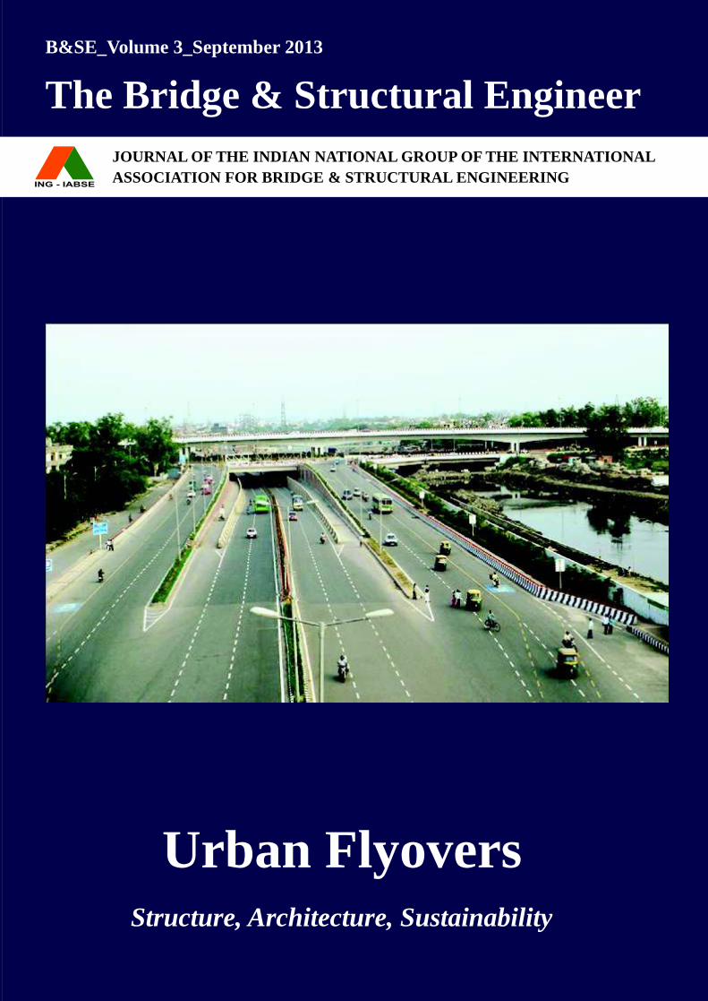
Urban Flyovers Structure, Architecture, Sustainability
B&SE_Volume 3_September 2013
The Bridge & Structural Engineer
JOURNAL OF THE INDIAN NATIONAL GROUP OF THE INTERNATIONAL
ASSOCIATION FOR BRIDGE & STRUCTURAL ENGINEERING
The Bridge and Structural Engineer Volume 43 Number 3 September 2013 i
ii Volume 43 Number 3 September 2013 The Bridge and Structural Engineer
L & T - R a m b o L L C o n s u L T i n g E n g i n E E R s L i m i T E dC3-C7, Triton Square, Tel: 91-44-2250 99994th Floor, E-mail: [email protected] Industrial Estate, Web: www.ltramboll.comGuindy,Chennai – 600 032India.
The Bridge and Structural Engineer Volume 43 Number 3 September 2013 iii
Editorial• From the desk of Chairman, Editorial Board : Alok Bhowmick• From the desk of Guest Editor, Prof Mahesh Tandon
Special Topic : Urban Flyovers1. Design and Construction Aspects of Approach
Structure to Signature Bridge at Wazirabad, New Delhi 1
Jose Kurian, SK Rustagi, Pradeep Garg, Mahesh Tandon, Jatinder Singh Pahuja
2. 3-Level Grade Separator at Ghazipur on National Highway-24 23
Mahesh Tandon, Shishir Bansal 3. Design & Construction of Grade Separator
near Apsara Border, Delhi 34 Alok Bhowmick4. Planning and Design of Precast Segmental
Flyover at Bhosari on NH-50 53 Nirav Mody, Umesh Rajeshirke5. Elevated Road Over Barapullah Nalla from
Sarai Kale Khan to Jawahar Lal Nehru Stadium : Construction Aspects 59
Sarvagya Srivastava, VK Singh6. Design Aspects of Barapullah Elevated Corridor 70 Ashish Srivastava, Priyank Mittal7. Considerations for Reinforced Soil Walls in
Urban Flyovers 80 Rajiv Goel8. Urban Flyover: Bridge Aesthetics, Illumination
and Landscaping 97 Sourabh Gupta, Mridu Sahai9. A Perspective on Maintenance Needs of
Urban Flyovers 106 Lakshmy Parameswaran
Research Papers1. EvaluationofDynamicAmplificationFactorfor
Beam Like Structures Subjected to Moving Load 117 K Saravana Kumar, Saptarshi Sasmal,
Voggu Srinivas, K Ramanjaneyulu2. Effect of Partial Interaction Theories for Steel
Concrete Composite Girder 130 Vinay Chaganti, Akhil Upadhyay3. Performance of Shrinkage and Creep Prediction
Models for Normal Strength Concrete 137 Banti A Gedam, Akhil Upadhyay, NM Bhandari
Panorama• About ING-IABSE 148• OfficeBearersandManagingCommitteeMembers2013 153• Obituary 156• ING-IABSE Membership Form 157
The Bridge and Structural EngineerIndian National Group of the International Association for Bridge and Structural Engineering
Co
nT
En
TS
Contents : Volume 3 : September 2013
1
2
3
4
5
6
iv Volume 43 Number 3 September 2013 The Bridge and Structural Engineer
The Bridge and Structural Engineer Volume 43 Number 3 September 2013 v• Price: ` 500
B&SE: The Bridge and Structural Engineer, is a quarterly journal published by ING-IABSE. It is one of the oldest and the foremost structural engineering Journal of its kind and repute in India. It was founded way back in 1957 and since then the journal is relentlessly disseminating latest technological progress in the spheres of structural engineering and bridging the gap between professionals and academics. Articles in this journal are written by practicing engineers as well as academia from around the world. The journal got a long deserving face-lift, with effect from this September 2013 issue.
The
Brid
ge &
Str
uctu
ral E
ngin
eer,
Sept
embe
r 201
3Jo
urna
l of t
he In
dian
nat
iona
l Gro
up o
f the
Inte
rnat
iona
l Ass
ocia
tion
for B
ridge
& S
truc
tura
l Eng
inee
ring
The Bridge and Structural Engineer September 2013
Editorial Board
Chair :Alok Bhowmick,Managing Director, B&S Engineering Consultants Pvt. Ltd., Noida
Members :Mahesh Tandon,Managing Director, Tandon Consultants Pvt. Ltd., New DelhiAK Banerjee, Former Member (Tech) NHAI, New DelhiHarshavardhan Subbarao,Chairman and Managing Director, CCP Ltd., Mumbainirmalya Bandyopadhyay,Director, STUP Consultants Pvt. Ltd., New DelhiJose Kurian, Chief Engineer, DTTDC Ltd., New DelhiSC Mehrotra, Chief Executive, Mehro Consultants, New Delhi
Advisors :AD narain, Former DG (RD) & Additional Secretary to the GOInK Sinha, Former DG (RD) & Special Secretary to the GOIGSharan, Former DG (RD) & Special Secretary to the GOIAV Sinha, Former DG (RD) & Special Secretary to the GOISK Puri, Former DG (RD) & Special Secretary to the GOIRP Indoria, Former DG (RD) & Special Secretary to the GOISS Chakraborty, Chairman, CES (India) Pvt. Ltd., New DelhiBC Roy, Senior Executive Director, JACOBS-CES, Gurgaon
Published :Quarterly : March, June, September and December
Publisher :ING-IABSEC/o Secretary, Indian National Group of the IABSEIDA Building, Ground Floor (Room No.12)Jamnagar House, Shahjahan RoadNew Delhi-110011, IndiaPhone: 91+011+23386724, 23782923 Telefax: 91+011+23388132E-mail: [email protected], [email protected], [email protected]
Submission of Papers : All editorial communications should be addressed to Chairman, Editorial Board of Indian National Group of the IABSE, IDA Building, Ground Floor, (Room No. 12), Jamnagar House, Shahjahan Road, New Delhi – 110011.
Advertising: All enquiries and correspondence in connection with advertising and the Equipments/Materials and Industry News Sections, should be addressed to Shri RK Pandey, Secretary, Indian National Group of the IABSE, IDA Building, Ground Floor, (Room No. 12), Jamnagar House, Shahjahan Road, New Delhi-110011.
Disclaimer :
All material published in this B&SE journal undergoes peer review to ensure fair balance, objectivity, independence and relevance. The contents of this journal are however contributions of individual authors and reflect their independent opinions. Neither the members of the editorial board, nor its publishers will be liable for any direct, indirect, consequential, special, exemplary or other damages arising from any misrepresentation in the papers.
The advertisers & the advertisement in this journal have no influence on editorial content or presentation. The posting of particular advertisement in this journal does not imply endorsement of the product or the company selling them by ING-IABSE, the B&SE journal or its Editors.
Front Cover :Bird’s eye view of the 3-level Grade Separator at Ghazipur on NH-24, Delhi
Content Sheet :Photo 1: Precast Segmental Box Girder Deck for the Western Approach to Signature Bridge over river Yamuna at WazirabadPhoto 2: Foot Over Bridge at 3-level Grade Separator at Ghazipur on NH-24, DelhiPhoto 3: Erection of Waler Beam over Contiguous Pile in progress at the site of Grade Separator near Apsara Border, DelhiPhoto 4: Erection of Segments in progress for the Bhosari Flyover on NH-50 at PunePhoto 5: Cast-in-situ Cantilever construction of Superstructure in progress over Lala Lajpat Rai Marg, New Delhi Photo 6: Various forms of Polymeric geogrids used in RS Walls
vi Volume 43 Number 3 September 2013 The Bridge and Structural Engineer
From the Desk of Chairman, Editorial Board
To be selected as Chairman of the Editorial Board for one of the oldest journal in India, namely “The Bridge and Structural Engineer” (B&SE), published by
ING-IABSE, is an honor, accepted with great pride but much humility. As I begin this responsibility, I am humbled by the great outpouring of technical support that I received from my colleagues in the Executive Committee, Editorial Board & Advisory Board of ING-IABSE and from the various authors of this issue, who contributed immensely with promptness in this endeavor to transform the journal.
With the publication of this issue of the journal of B&SE, a new chapter has begun. B&SE has been serving for last 56 years, starting 1957, as a fruitful companion to India’s Civil Engineering community. The magical journey for this quarterly journal has undergone a transformation effective this publication. From this issue, the journal is going to have following added features:
1. A transformation from Black & White to Color
2. Change in the size of the Magazine. The Magazine will be in A-4 sized.
3. Every issue will have focus on a particular theme. This September issue is focused on the theme of “Urban Flyovers”.
4. Hard core research papers are also included in the Journal.
The journal will encourage articles from both academic and industrial domains. In general the journal is open to quality articles from any area of Structural Engineering. The policy of the journal is to print only selected papers which have been peer reviewed.
With a very able editorial team, I am sure thereaderswillfindthistransformedjournalof B&SE to be a powerful tool and a useful companion. This journal has served for over 50 years and hopes to be there with more aggression for next many more 50 years, to enhance reader’s insight of the discipline of ‘civil engineering’ in general and ‘structural engineering’ in particular.
For this special issue, which is focused on the theme of ‘Urban Flyovers’, we are privileged to have Prof. Mahesh Tandon as our Guest Editor. Prof. Mahesh Tandon is a wellknownpersonalityinthefieldofstructuralengineering and hardly requires introduction. Hehasmadesignificantcontributionsinthedevelopment of a culture for innovation in structural engineering community, both within and outside India. He has been a motivating force for many young (and not so young) Engineers.
Happy reading!
ALoK BHoWMICK
vi Volume 43 Number 3 September 2013 The Bridge and Structural Engineer
The Bridge and Structural Engineer Volume 43 Number 3 September 2013 vii
From the Desk of Guest Editor
It is a matter of great pride for all members and well wishers of the Indian National Group of the IABSE to see The Bridge and Structural Engineer Quarterly Journal appear in its new
avatar from September 2013 and to welcome the appointment of a young and dynamic Chairman of the Editorial Board.
For this issue of the journal the theme selected is “Urban Flyovers”. The theme is most appropriate as a large number of structures in this category are being constructed in many cities of India and hopefully the contents of the journal would inspire aesthetic, fast-track constructions which are the need of the day. The papers presented in this issue cover only a small sample of this category of structures but they do represent the present status of design and construction technology in the country.
In all 12 papers have been selected for this issue. They have been carefully peer-reviewed and thereafter improved by the authors, wherever required. Six of the papers relate to the planning, design and construction of flyovers, grade separatorsinvolving underpasses and elevated road projects. Of additional interest are special papers on Architectural aspects, Mechanically stabilised walls for embankments and on Maintenance aspects offlyoverprojects.Inaddition,threeResearchpapersalsofindplaceinthisissue.
With the increase in urban population as well as the traffic, projects have become fairlycomplexascomparedto thesimpleflyoverwhich was adequate in the past. Multi-level traffic interchanges with atleast one levelbelow ground is now a common occurrence. Metro rail projects are simultaneously being planned for Indian cities with population of more than 2 million. This development has necessitated to have integrated planning for transportation projects both above and below ground insteadof treatinganurbanflyoverproject as an independent entity.
Traditionalconcernsofurbanflyoverswerelimited to concepts like economy, functionality, durability and riding comfort of the structure. In recent times more and more emphasis is being given to Sustainability issues of the project as well as Aesthetics of the structures constitutingtheflyover.
Harmonious integration of the structure into the built environment has become the top priority of human endeavour in any building activity. Structural engineers have a formidable responsibility to successive generations who will inherit the same environment.
Due to its sheer size and importance in sociological terms, a civil engineering structure looms prominently in the public consciousness. Implanting a large and permanent structure within the existing environs has significant repercussions,the detrimental effects of which are always significant. A deep involvement of thestructural designer in the evolution of the project is therefore essential. It has been found that the most important decisions relating to sustainability and aesthetics are
The Bridge and Structural Engineer Volume 43 Number 3 September 2013 vii
viii Volume 43 Number 3 September 2013 The Bridge and Structural Engineer
taken during the “evolution” or “formative” stages of design work. At later stages, the corrections from these considerations of badly conceived solutions can only result in marginal improvements unless the whole conceptionundergoesmajormodifications.
Some of the main issues which must be kept in mind can be summarized as follows:-
• Retain essential cultural and social characteristics of existing environment
• Encourage pedestrians, cyclists, public transport
• Incorporate signal-free movements of traffic to avoid atmospheric pollutionform stationary vehicles
• Incorporate Landscaping, drainage and rain water harvesting in the scheme
• Safety of road users during construction is to be considered as being paramount
• Aesthetics of structures is important for
people to ‘own’ the project
• Use blended cements to reduce carbon footprint
• Employ more embankments and less structure where appropriate to reduce carbon footprint
• Employ technologies which reduce construction period and minimize work on site
• Use of waste materials and industrial by-productslikeflyashandblastfurnanceslag should be incorporated
It is hoped that the selection of papers in this issue of the journal will, in a sense, provide areferencepointforfutureflyoverprojectsinthe country.
Happy reading!
MAHESH TAnDon
Profile of Prof Mahesh TandonProf MaheshTandon isan internationalexpert in thefieldof StructuralEngineering.Many of the structures designed by Prof Tandon have been widely acclaimed and have received recognition in India as well as internationally. He was appointed Distinguished Visiting Professor at the Indian Institute of Technologies at Kanpur and Roorkee by the Indian National Academy of Engineering (INAE) and the All India Council for Technical Education (AICTE).
He is a Fellow of INAE and was the Chairman of the National Information Center for Earthquake Engineering at IIT Kanpur and the past President of Indian Concrete Institute. He has spearheaded the development of many codes of practice on Concrete and on Bridge Structures in India.
AmongstthesignificantawardsreceivedbyProfTandonareLifetimeAchievementAwardby the Indian Concrete Institute(2003), National Award for Excellence in Consulting Engg Services(2004) by Consulting Engrs Association of India, S.B.Joshi Award by Alumni Association of College of Engineering Pune, etc. He was given the “Structural Engineer of the Year 2006” award by the Archidesign. He has been honoured by the Institution of Engineers (2010,2006) in recognition of his eminence and contribution to the profession ofCivilEngineering.Inaddition,hehasreceivedseveralawardsforspecificprojectsbyvarious professional institutions.
viii Volume 43 Number 3 September 2013 The Bridge and Structural Engineer
The Bridge and Structural Engineer Volume 43 Number 3 September 2013 1
Jose KURIAnChief Engineer
DTTDC New Delhi, INDIA
SK RUSTAGIChief Project Manager DTTDC New Delhi, [email protected]
Pradeep GARGSuperintending Engineer DTTDC New Delhi, [email protected]
Mahesh TAnDonManaging DirectorTandon Consultant Pvt Ltd New Delhi, [email protected]
Jatinder Singh PAHUJAPrincipal Consultant Tandon Consultant Pvt Ltd New Delhi, [email protected]
DESIGn AnD ConSTRUCTIon ASPECTS oF APPRoACH STRUCTURE To SIGnATURE BRIDGE AT WAzIRABAD,
nEW DELHI
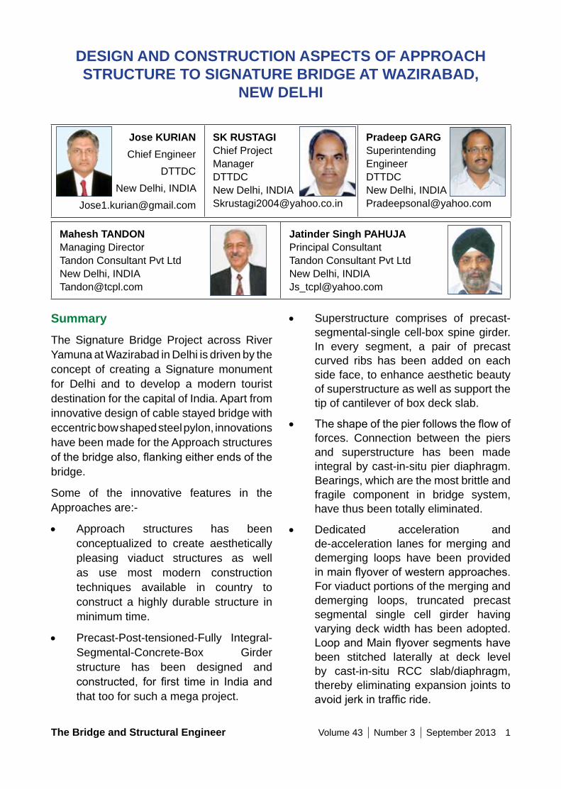
SummaryThe Signature Bridge Project across River Yamuna at Wazirabad in Delhi is driven by the concept of creating a Signature monument for Delhi and to develop a modern tourist destination for the capital of India. Apart from innovative design of cable stayed bridge with eccentric bow shaped steel pylon, innovations have been made for the Approach structures ofthebridgealso,flankingeitherendsofthebridge.
Some of the innovative features in the Approaches are:-
• Approach structures has been conceptualized to create aesthetically pleasing viaduct structures as well as use most modern construction techniques available in country to construct a highly durable structure in minimum time.
• Precast-Post-tensioned-Fully Integral-Segmental-Concrete-Box Girder structure has been designed and constructed, for first time in India andthat too for such a mega project.
• Superstructure comprises of precast-segmental-single cell-box spine girder. In every segment, a pair of precast curved ribs has been added on each side face, to enhance aesthetic beauty of superstructure as well as support the tip of cantilever of box deck slab.
• Theshapeofthepierfollowstheflowofforces. Connection between the piers and superstructure has been made integral by cast-in-situ pier diaphragm. Bearings, which are the most brittle and fragile component in bridge system, have thus been totally eliminated.
• Dedicated acceleration and de-acceleration lanes for merging and demerging loops have been provided inmainflyoverofwesternapproaches.For viaduct portions of the merging and demerging loops, truncated precast segmental single cell girder having varying deck width has been adopted. LoopandMainflyoversegmentshavebeen stitched laterally at deck level by cast-in-situ RCC slab/diaphragm, thereby eliminating expansion joints to avoidjerkintrafficride.
2 Volume 43 Number 3 September 2013 The Bridge and Structural Engineer
• Self Compacting Concrete of M60 & M65 grade, designed In-house, has beenusedextensively for first time inIndia for all piers and pier diaphragms of this work.
• Well (Cassion) foundation with Jack down sinking technology was adopted.
Keywords: aesthetics, box girder, curved ribs, fully integral bridge, jack down of well, precast segmental.
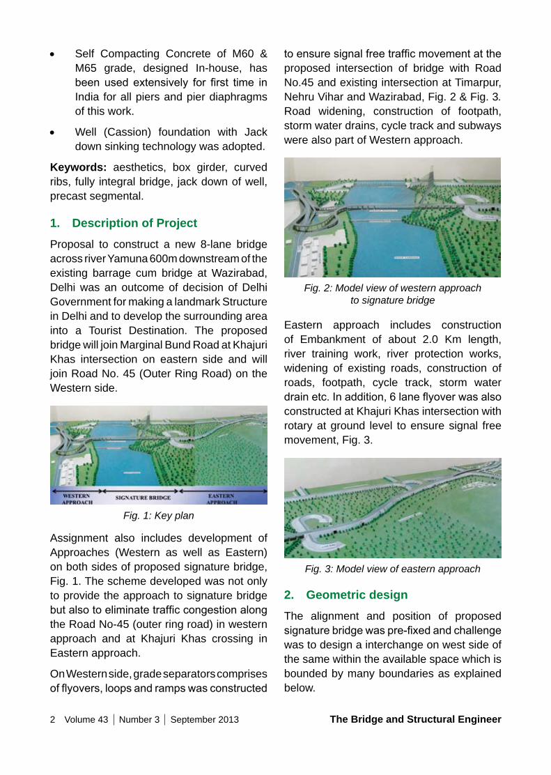
1. Description of ProjectProposal to construct a new 8-lane bridge across river Yamuna 600m downstream of the existing barrage cum bridge at Wazirabad, Delhi was an outcome of decision of Delhi Government for making a landmark Structure in Delhi and to develop the surrounding area into a Tourist Destination. The proposed bridge will join Marginal Bund Road at Khajuri Khas intersection on eastern side and will join Road No. 45 (Outer Ring Road) on the Western side.
Fig. 1: Key plan
Assignment also includes development of Approaches (Western as well as Eastern) on both sides of proposed signature bridge, Fig. 1. The scheme developed was not only to provide the approach to signature bridge butalsotoeliminatetrafficcongestionalongthe Road No-45 (outer ring road) in western approach and at Khajuri Khas crossing in Eastern approach.
On Western side, grade separators comprises offlyovers,loopsandrampswasconstructed
toensuresignalfreetrafficmovementattheproposed intersection of bridge with Road No.45 and existing intersection at Timarpur, Nehru Vihar and Wazirabad, Fig. 2 & Fig. 3. Road widening, construction of footpath, storm water drains, cycle track and subways were also part of Western approach.
Fig. 2: Model view of western approach to signature bridge
Eastern approach includes construction of Embankment of about 2.0 Km length, river training work, river protection works, widening of existing roads, construction of roads, footpath, cycle track, storm water drainetc.Inaddition,6laneflyoverwasalsoconstructed at Khajuri Khas intersection with rotary at ground level to ensure signal free movement, Fig. 3.
Fig. 3: Model view of eastern approach
2. Geometric designThe alignment and position of proposed signaturebridgewaspre-fixedandchallengewas to design a interchange on west side of the same within the available space which is bounded by many boundaries as explained below.
The Bridge and Structural Engineer Volume 43 Number 3 September 2013 3
addition, there are zones of acceleration and de-acceleration bays in western approach ontheflyoveralongtheRoadNo.45(OuterRing Road). Acceleration bay represent the zone wherein extra width of one lane is gradually provided over and above conventional main carriageway width so thattrafficcanbebranchedouttodivergingroad from main carriageway road. Similarly de-acceleration bay represent the zone wherein an converging road meets to main carriageway road.
Designing and constructing varying width of superstructure and also maintaining the rhythm of structural system opted for other conventional zones i.e precast segmental construction was a challenging job. This has been implemented by planning and close co-ordination between structural designers, client and contractor from conception to completion.
3. Form of superstructure cross-section
Broadly, superstructure comprises of precast segmentally constructed, single cell box spine girder of constant depth having precast curved ribs on both of its side to support the wide cantilever slab at its tip. 3.0m long precast segments accommodating two nos of curved ribs on each side of spine boxsegmentwasadopted.Outerprofileofcurved ribs and precast segments has been so shaped so as to maintain smooth curved bottomprofilefromoneendtoanotherend.These ribs were monolithically connected to spineboxatwebsoffit junctionat itbottomend and cantilever flange tip at its upperend.
Curved ribs has been shaped of varying width and varying thickness. Continuity of numbers of varying width of ribs in combination to spine box forms, arch shaped opening in between ribs in elevation to enhance the
(a) Existing Khyber pass boundary wall of DMRC was on west side.
(b) Tibetan colony on the south side.
(c) Grave yard is located on north side.
Various entries/exit which were planned has to be accommodated within the available space without any encroachment :-
• Entry to and exit from proposed signature bridge to ISBT side.
• Entry to and exit from proposed signature bridge to Azadpur side.
• Entry to and exit from proposed signature bridge to existing Wazirabad barrage cum bridge.
• Entry to and exit from proposed signature bridge to Timarpur.
• Wazirabad barrage cum bridge to ISBT and vice versa.
• Wazirabad barrage cum bridge to Timarpur and vice versa.
• Wazirabad barrage cum bridge to Azadpur and vice versa.
• Azadpur to ISBT and vice versa [along Road No. 45 (Outer Ring Road)]
After evaluating many alternatives, geometry though complex was envisaged within available space which was best possible and meets all geometrical requirements of standard practice, Fig. 2.
Apart from vehicular traffic, cycle tracks were also planned for all such movements except to signature bridge. Combining Eastern & Western approach nearly 50000 sqm of open portion of elevated flyover, 25000 sqm of closed portion ofviaduct & 90000 sqm of embankment was required to be constructed.
Flyover to be constructed was of different carriageway width 9.7 m, 11 m & 12.5 m. In
4 Volume 43 Number 3 September 2013 The Bridge and Structural Engineer
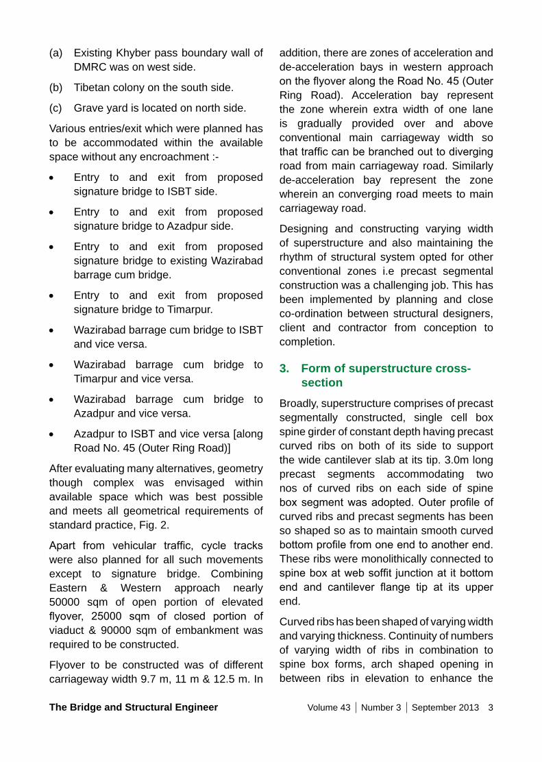
Table 6: Spine & Rib Details
10.3 m Wide Box
12.0 m Wide Box
13.2 m Wide Box
Type of Spine Box
Spine Box Type-1
Spine Box type-2
Type of Rib
Rib Type-1 Rib type-2
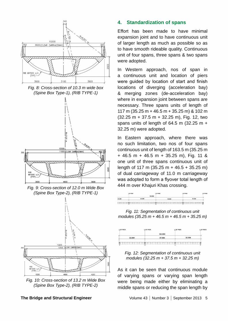
This was only possible by changing radius of spineboxprofilew.r.tradiusofoutercurvedprofile of rib but while doing so commontangent is maintained at the intersection of two, Fig. 8, Fig. 9 and Fig. 10. Such planning had resulted in requirement of only two types of moulds each for rib as well as precast segment for three different deck width.
For casting of segments, two long line beds and one short line bed were used. Short line bed was exclusively used for 12.0m wide segments (for spans having plan curvature limited to 1000m curve) while long line beds were used for 10.3m wide, 12.0m wide & 13.2 wide segments. Total numbers of segments which were casted for the elevated part of Eastern approach as well as Western approach structure are indicated in Table. 7 below:-
Table 7: Nos. of Precast segments
Nos. of Segments for Each Deck Width
Deck Width
10.3 m Wide Box
12.0 m Wide Box
13.2 m Wide Box
Total
Numbers of 3.0 m Long Segments
201 nos 780 nos 150 nos 1131 nos
Same spine boxes and ribs were also used for varying width of decks in acceleration and de-acceleration zone.
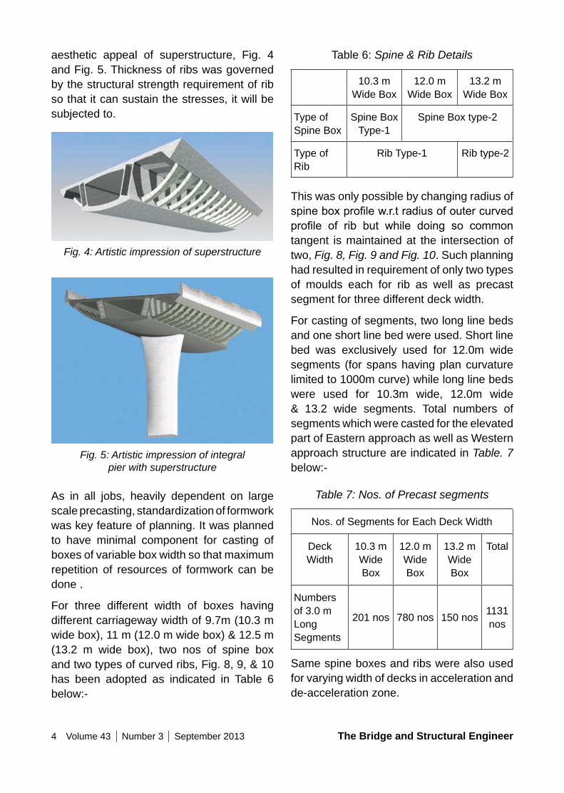
aesthetic appeal of superstructure, Fig. 4 and Fig. 5. Thickness of ribs was governed by the structural strength requirement of rib so that it can sustain the stresses, it will be subjected to.
Fig. 4: Artistic impression of superstructure
Fig. 5: Artistic impression of integral pier with superstructure
As in all jobs, heavily dependent on large scale precasting, standardization of formwork was key feature of planning. It was planned to have minimal component for casting of boxes of variable box width so that maximum repetition of resources of formwork can be done .
For three different width of boxes having different carriageway width of 9.7m (10.3 m wide box), 11 m (12.0 m wide box) & 12.5 m (13.2 m wide box), two nos of spine box and two types of curved ribs, Fig. 8, 9, & 10 has been adopted as indicated in Table 6 below:-
The Bridge and Structural Engineer Volume 43 Number 3 September 2013 5
4. Standardization of spansEffort has been made to have minimal expansion joint and to have continuous unit of larger length as much as possible so as to have smooth rideable quality. Continuous unit of four spans, three spans & two spans were adopted.
In Western approach, nos of span in a continuous unit and location of piers were guided by location of start and finishlocations of diverging (acceleration bay) & merging zones (de-acceleration bay) where in expansion joint between spans are necessary. Three spans units of length of 117 m (35.25 m + 46.5 m + 35.25 m) & 102 m (32.25 m + 37.5 m + 32.25 m), Fig. 12, two spans units of length of 64.5 m (32.25 m + 32.25 m) were adopted.
In Eastern approach, where there was no such limitation, two nos of four spans continuous unit of length of 163.5 m (35.25 m + 46.5 m + 46.5 m + 35.25 m), Fig. 11 & one unit of three spans continuous unit of length of 117 m (35.25 m + 46.5 + 35.25 m) of dual carriageway of 11.0 m carriageway wasadoptedtoformaflyovertotallengthof444 m over Khajuri Khas crossing.
Fig. 11: Segmentation of continuous unit modules (35.25 m + 46.5 m + 46.5 m + 35.25 m)
Fig. 12: Segmentation of continuous unit modules (32.25 m + 37.5 m + 32.25 m)
As it can be seen that continuous module of varying spans or varying span length were being made either by eliminating a middle spans or reducing the span length by
Fig. 8: Cross-section of 10.3 m wide box (Spine Box Type-1), (RIB TYPE-1)
Fig. 9: Cross-section of 12.0 m Wide Box (Spine Box Type-2), (RIB TYPE-1)
Fig. 10: Cross-section of 13.2 m Wide Box (Spine Box Type-2), (RIB TYPE-2)
6 Volume 43 Number 3 September 2013 The Bridge and Structural Engineer
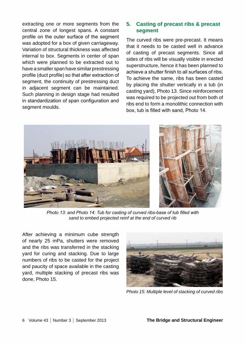
5. Casting of precast ribs & precast segment
The curved ribs were pre-precast. It means that it needs to be casted well in advance of casting of precast segments. Since all sides of ribs will be visually visible in erected superstructure, hence it has been planned to achieveashutterfinishtoallsurfacesofribs.To achieve the same, ribs has been casted by placing the shutter vertically in a tub (in casting yard), Photo 13. Since reinforcement was required to be projected out from both of ribs end to form a monolithic connection with box,tubisfilledwithsand,Photo14.
extracting one or more segments from the central zone of longest spans. A constant profileon theoutersurfaceof thesegmentwas adopted for a box of given carriageway. Variation of structural thickness was affected internal to box. Segments in center of span which were planned to be extracted out to have a smaller span have similar prestressing profile(ductprofile)sothatafterextractionofsegment, the continuity of prestressing duct in adjacent segment can be maintained. Such planning in design stage had resulted instandardizationofspanconfigurationandsegment moulds.
Photo 13: and Photo 14: Tub for casting of curved ribs-base of tub filled with
sand to embed projected reinf at the end of curved rib
After achieving a minimum cube strength of nearly 25 mPa, shutters were removed and the ribs was transferred in the stacking yard for curing and stacking. Due to large numbers of ribs to be casted for the project and paucity of space available in the casting yard, multiple stacking of precast ribs was done, Photo 15.
Photo 15: Multiple level of stacking of curved ribs
The Bridge and Structural Engineer Volume 43 Number 3 September 2013 7
Photo 16: Placement of ribs of segments in long line bed
Photo 17: Placement of external shutter of web & cantilever of segment
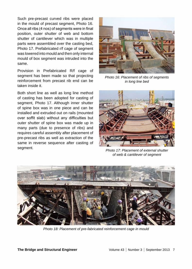
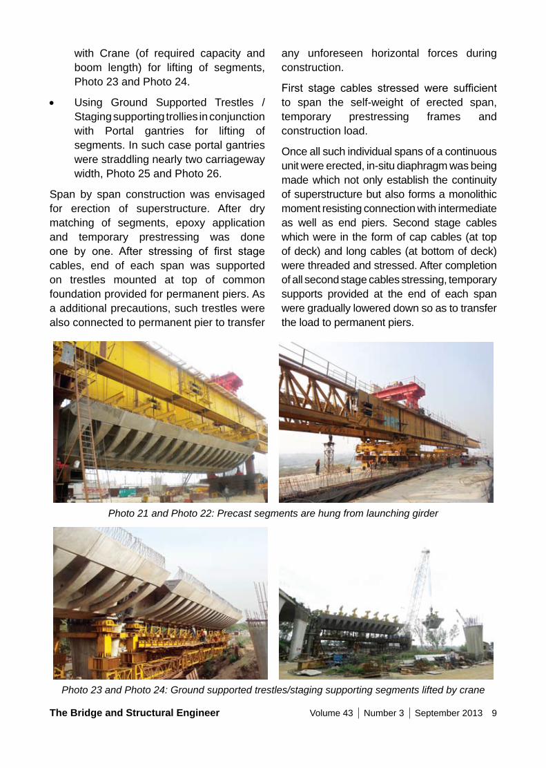
Such pre-precast curved ribs were placed in the mould of precast segment, Photo 16. Onceallribs(4nos)ofsegmentswereinfinalposition, outer shutter of web and bottom shutter of cantilever which was in multiple parts were assembled over the casting bed, Photo 17. Prefabricated r/f cage of segment was lowered into mould and then only internal mould of box segment was intruded into the same.
Provision in Prefabricated R/f cage of segment has been made so that projecting reinforcement from precast rib end can be taken inside it.
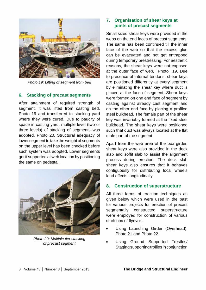
Both short line as well as long line method of casting has been adopted for casting of segment, Photo 17. Although inner shutter of spine box was in one piece and can be installed and extruded out on rails (mounted over soffit slab) without any difficulties butouter shutter of spine box was made up in many parts (due to presence of ribs) and requires careful assembly after placement of pre-precast ribs as well as extraction of the same in reverse sequence after casting of segment.
Photo 18: Placement of pre-fabricated reinforcement cage in mould
8 Volume 43 Number 3 September 2013 The Bridge and Structural Engineer
7. organisation of shear keys at joints of precast segments
Small sized shear keys were provided in the webs on the end faces of precast segments. The same has been continued till the inner face of the web so that the excess glue can be evacuated and not get entrapped during temporary prestressing. For aesthetic reasons, the shear keys were not exposed at the outer face of web, Photo 19. Due to presence of internal tendons, shear keys are positioned differently at every segment by eliminating the shear key where duct is placed at the face of segment. Shear keys were formed on one end face of segment by casting against already cast segment and on theotherend facebyplacingaprofiledsteel bulkhead. The female part of the shear keywasinvariablyformedatthefixedsteelbulkhead. The shear keys were positioned suchthatductwasalwayslocatedattheflatmale part of the segment.
Apart from the web area of the box girder, shear keys were also provided in the deck slab and soffit slab to assist the alignmentprocess during erection. The deck slab shear keys also ensures that it behaves contiguously for distributing local wheels load effects longitudinally.
8. Construction of superstructureAll three forms of erection techniques as given below which were used in the past for various projects for erection of precast segmentally constructed superstructure were employed for construction of various stretchesofflyover:-
• Using Launching Girder (Overhead), Photo 21 and Photo 22.
• Using Ground Supported Trestles/ Staging supporting trollies in conjunction
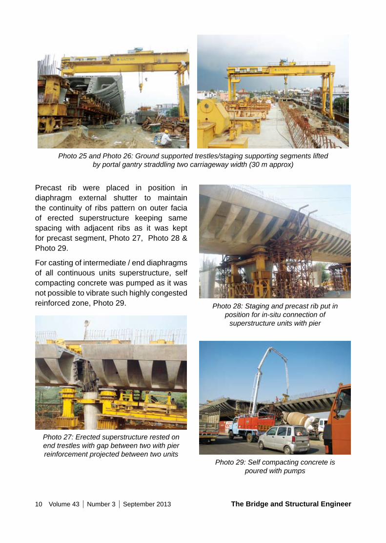
Photo 19: Lifting of segment from bed
6. Stacking of precast segmentsAfter attainment of required strength of segment, it was lifted from casting bed, Photo 19 and transferred to stacking yard where they were cured. Due to paucity of space in casting yard, multiple level (two or three levels) of stacking of segments was adopted, Photo 20. Structural adequacy of lower segment to take the weight of segments on the upper level has been checked before such system was adopted. Lower segments got it supported at web location by positioning the same on pedestal.
Photo 20: Multiple tier stacking of precast segment
The Bridge and Structural Engineer Volume 43 Number 3 September 2013 9
any unforeseen horizontal forces during construction.
First stage cables stressed were sufficientto span the self-weight of erected span, temporary prestressing frames and construction load.
Once all such individual spans of a continuous unit were erected, in-situ diaphragm was being made which not only establish the continuity of superstructure but also forms a monolithic moment resisting connection with intermediate as well as end piers. Second stage cables which were in the form of cap cables (at top of deck) and long cables (at bottom of deck) were threaded and stressed. After completion of all second stage cables stressing, temporary supports provided at the end of each span were gradually lowered down so as to transfer the load to permanent piers.
with Crane (of required capacity and boom length) for lifting of segments, Photo 23 and Photo 24.
• Using Ground Supported Trestles / Staging supporting trollies in conjunction with Portal gantries for lifting of segments. In such case portal gantries were straddling nearly two carriageway width, Photo 25 and Photo 26.
Span by span construction was envisaged for erection of superstructure. After dry matching of segments, epoxy application and temporary prestressing was done one by one. After stressing of first stagecables, end of each span was supported on trestles mounted at top of common foundation provided for permanent piers. As a additional precautions, such trestles were also connected to permanent pier to transfer
Photo 21 and Photo 22: Precast segments are hung from launching girder
Photo 23 and Photo 24: Ground supported trestles/staging supporting segments lifted by crane
10 Volume 43 Number 3 September 2013 The Bridge and Structural Engineer
Photo 28: Staging and precast rib put in position for in-situ connection of
superstructure units with pier
Photo 29: Self compacting concrete is poured with pumps
Precast rib were placed in position in diaphragm external shutter to maintain the continuity of ribs pattern on outer facia of erected superstructure keeping same spacing with adjacent ribs as it was kept for precast segment, Photo 27, Photo 28 & Photo 29.
For casting of intermediate / end diaphragms of all continuous units superstructure, self compacting concrete was pumped as it was not possible to vibrate such highly congested reinforced zone, Photo 29.
Photo 27: Erected superstructure rested on end trestles with gap between two with pier reinforcement projected between two units
Photo 25 and Photo 26: Ground supported trestles/staging supporting segments lifted
by portal gantry straddling two carriageway width (30 m approx)
The Bridge and Structural Engineer Volume 43 Number 3 September 2013 11
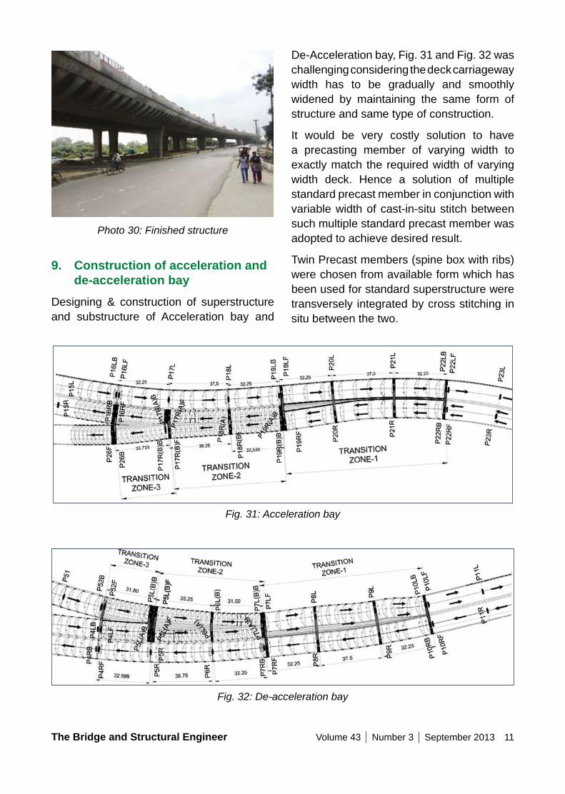
De-Acceleration bay, Fig. 31 and Fig. 32 was challenging considering the deck carriageway width has to be gradually and smoothly widened by maintaining the same form of structure and same type of construction.
It would be very costly solution to have a precasting member of varying width to exactly match the required width of varying width deck. Hence a solution of multiple standard precast member in conjunction with variable width of cast-in-situ stitch between such multiple standard precast member was adopted to achieve desired result.
Twin Precast members (spine box with ribs) were chosen from available form which has been used for standard superstructure were transversely integrated by cross stitching in situ between the two.
Photo 30: Finished structure
9. Construction of acceleration and de-acceleration bay
Designing & construction of superstructure and substructure of Acceleration bay and
Fig. 31: Acceleration bay
Fig. 32: De-acceleration bay
12 Volume 43 Number 3 September 2013 The Bridge and Structural Engineer
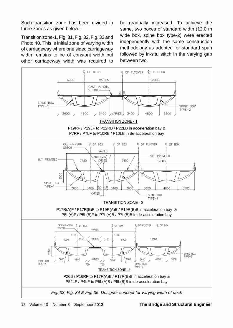
Such transition zone has been divided in three zones as given below:-
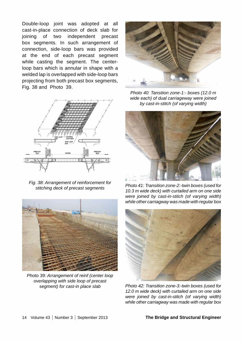
Transition zone-1, Fig. 31, Fig. 32, Fig. 33 and Photo 40. This is initial zone of varying width of carriageway where one sided carriageway width remains to be of constant width but other carriageway width was required to
be gradually increased. To achieve the same, two boxes of standard width (12.0 m wide box, spine box type-2) were erected independently with the same construction methodology as adopted for standard span followed by in-situ stitch in the varying gap between two.
P19RF / P19LF to P22RB / P22LB in acceleration bay & P7RF / P7LF to P10RB / P10LB in de-acceleration bay
P17R(A)F / P17R(B)F to P19R(A)B / P19R(B)B in acceleration bay & P5L(A)F / P5L(B)F to P7L(A)B / P7L(B)B in de-acceleration bay
P26B / P16RF to P17R(A)B / P17R(B)B in acceleration bay & P52LF / P4LF to P5L(A)B / P5L(B)B in de-acceleration bay
Fig. 33, Fig. 34 & Fig. 35: Designer concept for varying width of deck
The Bridge and Structural Engineer Volume 43 Number 3 September 2013 13
Transition zone-2, Fig. 31, Fig. 32, Fig. 34 & Photo 41. This is middle zone of varying width of carriageway. To achieve the same, two boxes (as used for 10.3 m wide box, spine box type-1) with curtailed arm on one side were erected independently with the same construction methodology as adopted for standard span followed by in situ stich between two in varying gap. Such box section was geometrical un-symmetrical about vertical axes due to curtailed arm on one side of box resulting in plan eccentricity. To counteract such effect of plan eccentricity, transverse slits, Fig. 34 was provided in deck slab (on cantilever side) of precast segments so that prestressing force does not flow in the un-symmetric part andeffect of prestress remains symmetric about spine box section. Such slits were provided at precast segment joints as well as in the middle of segment. After completion of all prestressing in spine box, such transverse slitswerefilledwithgrout.Acablewasalsostressed through hole left in cantilever tip to impart axial compression across such slited joints in slab after achievement of required strength of grout.
Transition zone-3, Fig. 31, Fig. 32, Fig. 34 and Photo 42. This is end zone of varying width of carriageway. To achieve the same, two boxes (as used for 12.0 m wide box, spine box type-2) with curtailed arm on one
side were erected independently with the same construction methodology as adopted for standard span followed by in-situ stitch in the varying gap between two. Chosen box section was also geometrical un-symmetrical about vertical axes resulting in plan eccentricity. To counteract such effect of planeccentricity,nosofstrandsinpredefinedcables location were varied on left side of box and right side of box so that no net primary moment is generated about vertical axes of box section. This was only possible as box spine used in this zone was quite wide and plan eccentricity was not too much. Of course such un-symmetric prestressing draped in webs had caused torsion and box structure has been designed for the same.
Due to variation in structural system of three transition zones, all such transition zones were separated by expansion joint.
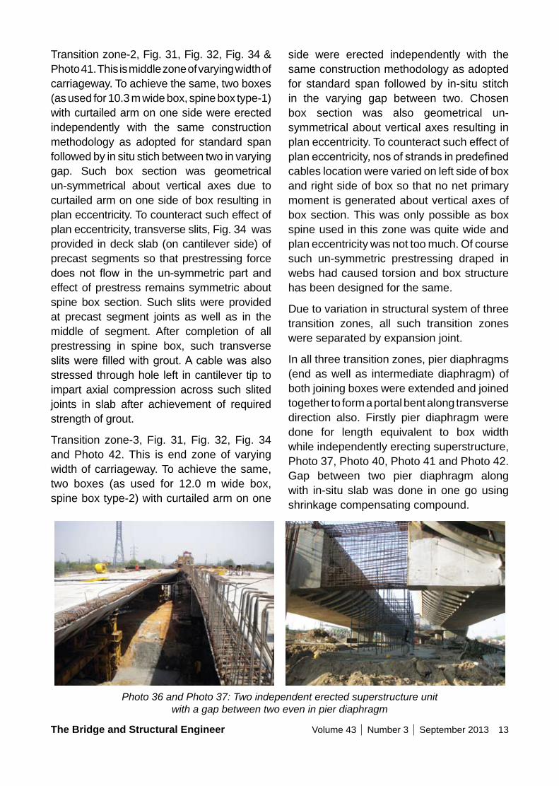
In all three transition zones, pier diaphragms (end as well as intermediate diaphragm) of both joining boxes were extended and joined together to form a portal bent along transverse direction also. Firstly pier diaphragm were done for length equivalent to box width while independently erecting superstructure, Photo 37, Photo 40, Photo 41 and Photo 42. Gap between two pier diaphragm along with in-situ slab was done in one go using shrinkage compensating compound.
Photo 36 and Photo 37: Two independent erected superstructure unit
with a gap between two even in pier diaphragm
14 Volume 43 Number 3 September 2013 The Bridge and Structural Engineer
Photo 40: Tansition zone-1:- boxes (12.0 m wide each) of dual carriageway were joined
by cast-in-stitch (of varying width)
Photo 41: Transition zone-2:-twin boxes (used for 10.3 m wide deck) with curtailed arm on one side were joined by cast-in-stitch (of varying width) while other carriagway was made with regular box
Photo 42: Transition zone-3:-twin boxes (used for 12.0 m wide deck) with curtailed arm on one side were joined by cast-in-stitch (of varying width) while other carriagway was made with regular box
Double-loop joint was adopted at all cast-in-place connection of deck slab for joining of two independent precast box segments. In such arrangement of connection, side-loop bars was provided at the end of each precast segment while casting the segment. The center-loop bars which is annular in shape with a welded lap is overlapped with side-loop bars projecting from both precast box segments, Fig. 38 and Photo 39.
Fig. 38: Arrangement of reinforcement for stitching deck of precast segments
Photo 39: Arrangement of reinf (center loop overlapping with side loop of precast
segment) for cast-in place slab
The Bridge and Structural Engineer Volume 43 Number 3 September 2013 15
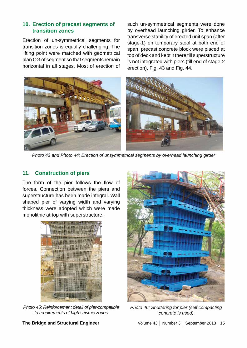
such un-symmetrical segments were done by overhead launching girder. To enhance transverse stability of erected unit span (after stage-1) on temporary stool at both end of span, precast concrete block were placed at top of deck and kept it there till superstructure is not integrated with piers (till end of stage-2 erection), Fig. 43 and Fig. 44.
10. Erection of precast segments of transition zones
Erection of un-symmetrical segments for transition zones is equally challenging. The lifting point were matched with geometrical plan CG of segment so that segments remain horizontal in all stages. Most of erection of
Photo 43 and Photo 44: Erection of unsymmetrical segments by overhead launching girder
Photo 46: Shuttering for pier (self compacting concrete is used)
11. Construction of piersThe form of the pier follows the flow offorces. Connection between the piers and superstructure has been made integral. Wall shaped pier of varying width and varying thickness were adopted which were made monolithic at top with superstructure.
Photo 45: Reinforcement detail of pier-compatible to requirements of high seismic zones
16 Volume 43 Number 3 September 2013 The Bridge and Structural Engineer
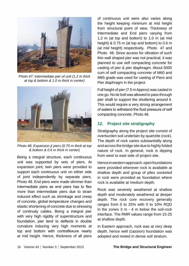
of continuous unit were also varies along the height keeping minimum at mid height from structural point of view. Thickness of Intermediate and End piers varying from 1.2 m (at top and bottom) to 1.0 m (at mid height) & 0.75 m (at top and bottom) to 0.6 m (at mid height) respectively, Photo 47 and Photo 48. Since access for vibration of such thin wall shaped pier was not practical, it was planned to use self compacting concrete for casting of pier & pier diaphragm. About 5000 cum of self compacting concrete of M60 and M65 grade was used for casting of Piers and Pier diaphragm in the project.
Full height of pier (7.5 m Approx) was casted in one go. No tie bolt was allowed to pass through pier shaft to support the shuttering around it. This would require a very strong arrangement ofwalerstowithstandthefluidpressureofselfcompacting concrete, Photo 46.
12. Project site stratigraphyStratigraphy along the project site consist of overburden soil underlain by quartzite (rock). The depth of rock varies substantially along and across the bridge site due to highly folded nature of rock. In general, rock is dipping from west to east side of project site.
Hence in western approach, open foundations were provided wherever rock is available at shallow depth and group of piles socketed in rock were provided as foundation where rock is available at medium depth.
Rock was severely weathered at shallow depth and moderately weathered at deeper depth. The rock core recovery generally ranges from 0 to 25% with 0 to 10% RQD in the zones 3 m - 4 m below the soil-rock interface. The RMR values range from 15-25 at shallow depth.
In Eastern approach, rock was at very deep depth, hence well (cassion) foundation was adopted and rested in dense soil stratum.
Photo 47: Intermediate pier of unit (1.2 m thick at top & bottom & 1.0 m thick in center)
Photo 48: Expansion jt piers (0.75 m thick at top & bottom & 0.6 m thick in center)
Being a integral structure, each continuous unit was supported by sets of piers. At expansion joint, twin piers were provided to support each continuous unit on either side of joint independently by separate piers, Photo 48. End piers were made slimmer than intermediate piers as end piers has to flexmore than intermediate piers due to strain induced effect such as shrinkage and creep of concrete, global temperature changes and elastic shortening of concrete due to stressing of continuity cables. Being a integral pier with very high rigidity of superstructure and foundation, pier tend to deflects in doublecurvature inducing very high moments at top and bottom with contraflexure nearlyat mid height. Hence, thickness of all piers
The Bridge and Structural Engineer Volume 43 Number 3 September 2013 17
14. Construction of well foundationDetailed soil survey was conducted at every pier location in Eastern approach, which indicated more or less similar soil characteristics. Upper stratum comprises offinesand (upto10.0 m) followed by silty clay with small pebbles (upto 19.5 m). Lower stratum (19.5 m to 60.0 m) consists predominantly of sandy silt of low plasticity and clayey silt of low to medium plasticity. SPT values ranging from 25 to more than 100 exhibiting very stiff to hard consistency of strata.
A detailed study was carried out to identify the depth of potential of liquefaction in upper layer of soil and it has been concluded that upper 10-12 m soil are having liquefaction potential under seismic event. The formation levelofflyoverwasnearly16mabove thebed level. Proposal of pile foundation, even with large diameter of pile was not practical as it was becoming too slender in seismic event.
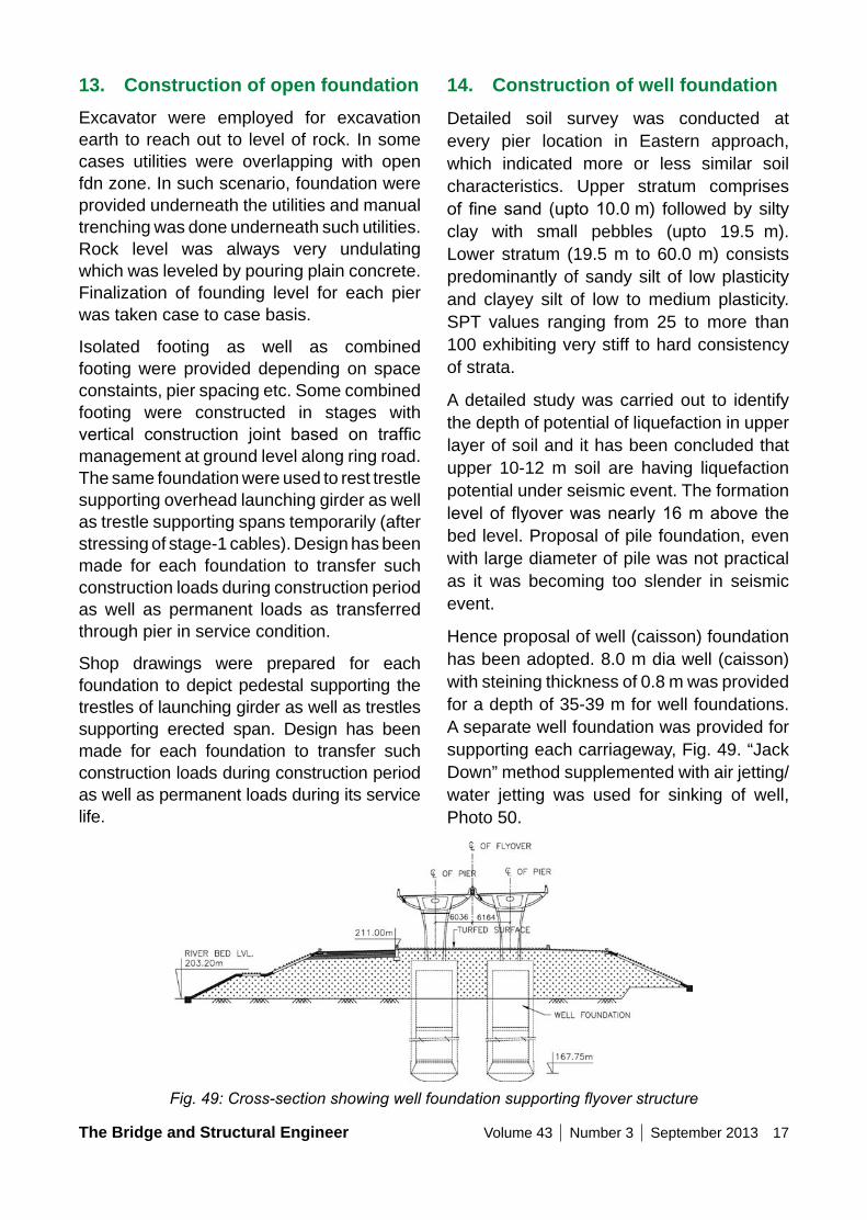
Hence proposal of well (caisson) foundation has been adopted. 8.0 m dia well (caisson) with steining thickness of 0.8 m was provided for a depth of 35-39 m for well foundations. A separate well foundation was provided for supporting each carriageway, Fig. 49. “Jack Down” method supplemented with air jetting/water jetting was used for sinking of well, Photo 50.
13. Construction of open foundationExcavator were employed for excavation earth to reach out to level of rock. In some cases utilities were overlapping with open fdn zone. In such scenario, foundation were provided underneath the utilities and manual trenching was done underneath such utilities. Rock level was always very undulating which was leveled by pouring plain concrete. Finalization of founding level for each pier was taken case to case basis.
Isolated footing as well as combined footing were provided depending on space constaints, pier spacing etc. Some combined footing were constructed in stages with vertical construction joint based on trafficmanagement at ground level along ring road. The same foundation were used to rest trestle supporting overhead launching girder as well as trestle supporting spans temporarily (after stressing of stage-1 cables). Design has been made for each foundation to transfer such construction loads during construction period as well as permanent loads as transferred through pier in service condition.
Shop drawings were prepared for each foundation to depict pedestal supporting the trestles of launching girder as well as trestles supporting erected span. Design has been made for each foundation to transfer such construction loads during construction period as well as permanent loads during its service life.
Fig. 49: Cross-section showing well foundation supporting flyover structure
18 Volume 43 Number 3 September 2013 The Bridge and Structural Engineer
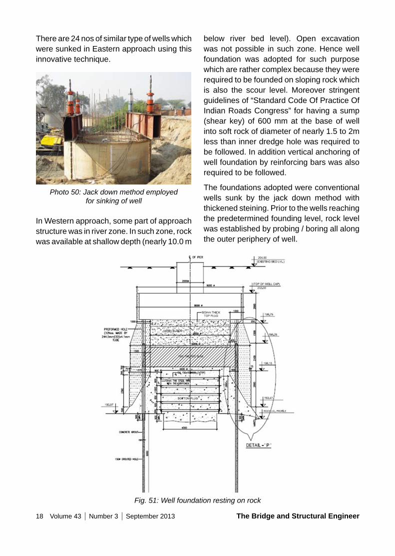
below river bed level). Open excavation was not possible in such zone. Hence well foundation was adopted for such purpose which are rather complex because they were required to be founded on sloping rock which is also the scour level. Moreover stringent guidelines of “Standard Code Of Practice Of Indian Roads Congress” for having a sump (shear key) of 600 mm at the base of well into soft rock of diameter of nearly 1.5 to 2m less than inner dredge hole was required to be followed. In addition vertical anchoring of well foundation by reinforcing bars was also required to be followed.
The foundations adopted were conventional wells sunk by the jack down method with thickened steining. Prior to the wells reaching the predetermined founding level, rock level was established by probing / boring all along the outer periphery of well.
There are 24 nos of similar type of wells which were sunked in Eastern approach using this innovative technique.
Photo 50: Jack down method employed for sinking of well
In Western approach, some part of approach structure was in river zone. In such zone, rock was available at shallow depth (nearly 10.0 m
Fig. 51: Well foundation resting on rock
The Bridge and Structural Engineer Volume 43 Number 3 September 2013 19
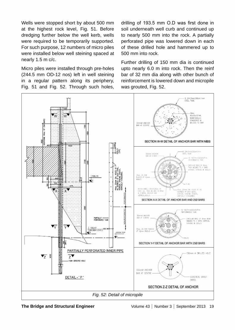
Wells were stopped short by about 500 mm at the highest rock level, Fig. 51. Before dredging further below the well kerb, wells were required to be temporarily supported. For such purpose, 12 numbers of micro piles were installed below well steining spaced at nearly 1.5 m c/c.
Micro piles were installed through pre-holes (244.5 mm OD-12 nos) left in well steining in a regular pattern along its periphery, Fig. 51 and Fig. 52. Through such holes,
drilling of 193.5mmO.Dwas first done insoil underneath well curb and continued up to nearly 500 mm into the rock. A partially perforated pipe was lowered down in each of these drilled hole and hammered up to 500 mm into rock.
Further drilling of 150 mm dia is continued upto nearly 6.0 m into rock. Then the reinf bar of 32 mm dia along with other bunch of reinforcement is lowered down and micropile was grouted, Fig. 52.
Fig. 52: Detail of micropile
20 Volume 43 Number 3 September 2013 The Bridge and Structural Engineer
casted which was mainly as a safeguard to receive the upward pressure on the plug. The well is then completed in the normal manner. Inside opening ofwellwas filledwith sandand capped by a layer of concrete. The well cap and pier were thereafter executed in the normal manner.
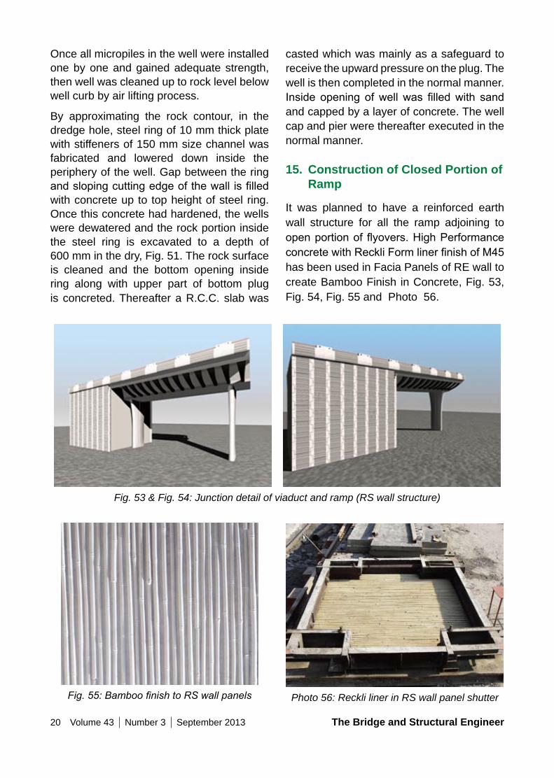
15. Construction of Closed Portion of Ramp
It was planned to have a reinforced earth wall structure for all the ramp adjoining to openportionofflyovers.HighPerformanceconcretewithReckliFormlinerfinishofM45has been used in Facia Panels of RE wall to create Bamboo Finish in Concrete, Fig. 53, Fig. 54, Fig. 55 and Photo 56.
Once all micropiles in the well were installed one by one and gained adequate strength, then well was cleaned up to rock level below well curb by air lifting process.
By approximating the rock contour, in the dredge hole, steel ring of 10 mm thick plate with stiffeners of 150 mm size channel was fabricated and lowered down inside the periphery of the well. Gap between the ring andslopingcuttingedgeofthewallisfilledwith concrete up to top height of steel ring. Once this concrete had hardened, the wells were dewatered and the rock portion inside the steel ring is excavated to a depth of 600 mm in the dry, Fig. 51. The rock surface is cleaned and the bottom opening inside ring along with upper part of bottom plug is concreted. Thereafter a R.C.C. slab was
Fig. 53 & Fig. 54: Junction detail of viaduct and ramp (RS wall structure)
Fig. 55: Bamboo finish to RS wall panels Photo 56: Reckli liner in RS wall panel shutter
The Bridge and Structural Engineer Volume 43 Number 3 September 2013 21
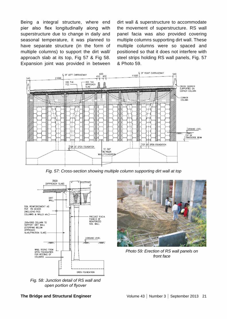
dirt wall & superstructure to accommodate the movement of superstructure. RS wall panel facia was also provided covering multiple columns supporting dirt wall. These multiple columns were so spaced and positioned so that it does not interfere with steel strips holding RS wall panels, Fig. 57 & Photo 59.
Being a integral structure, where end pier also flex longitudinally along withsuperstructure due to change in daily and seasonal temperature, it was planned to have separate structure (in the form of multiple columns) to support the dirt wall/ approach slab at its top, Fig 57 & Fig 58. Expansion joint was provided in between
Fig. 57: Cross-section showing multiple column supporting dirt wall at top
Fig. 58: Junction detail of RS wall and open portion of flyover
Photo 59: Erection of RS wall panels on front face
22 Volume 43 Number 3 September 2013 The Bridge and Structural Engineer
beautiful flyover structure in the landscapeof New Delhi.
17. CreditsThe project recently received the award in the category of “Innovative Application Of Special Concretes” for the year 2012 by Indian Concrete Institute.
Client : Delhi Tourism And Transportation Development Ltd. (DTTDC), India.
Consultants
Prime Consultant and Structural Design : Tandon
Consultant Pvt Ltd, New Delhi, India.
Proof Consultant : Construma Consultancy Pvt Ltd., Mumbai, India.
Contractor : Gammon India Pvt Ltd., India.
Other Details of ProjectContract Amount : Rs 348.9 cr
Commencement of Work : June 2008
Duration of Work : 42 Months
Schedule Completion : December 2011
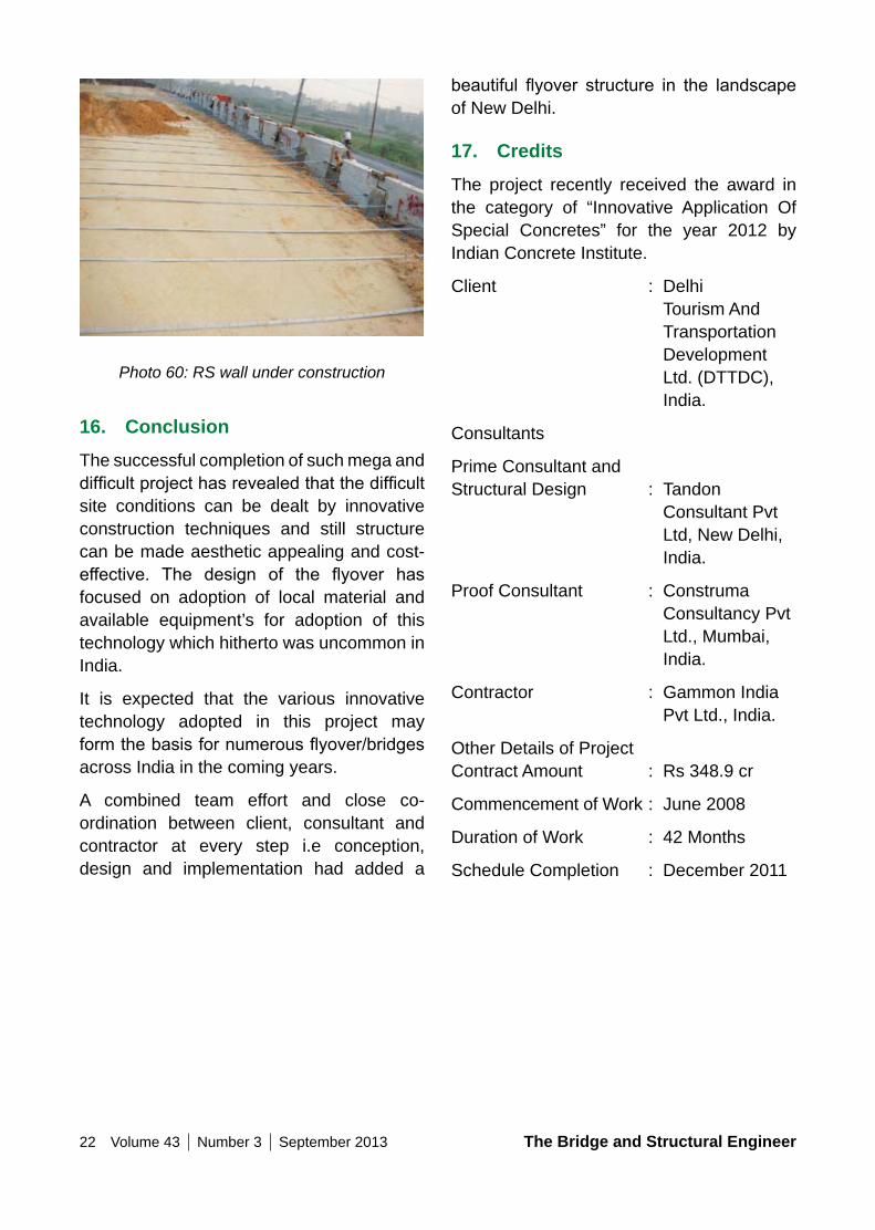
Photo 60: RS wall under construction
16. ConclusionThe successful completion of such mega and difficultprojecthasrevealedthatthedifficultsite conditions can be dealt by innovative construction techniques and still structure can be made aesthetic appealing and cost-effective. The design of the flyover hasfocused on adoption of local material and available equipment’s for adoption of this technology which hitherto was uncommon in India.
It is expected that the various innovative technology adopted in this project may formthebasisfornumerousflyover/bridgesacross India in the coming years.
A combined team effort and close co-ordination between client, consultant and contractor at every step i.e conception, design and implementation had added a
The Bridge and Structural Engineer Volume 43 Number 3 September 2013 23
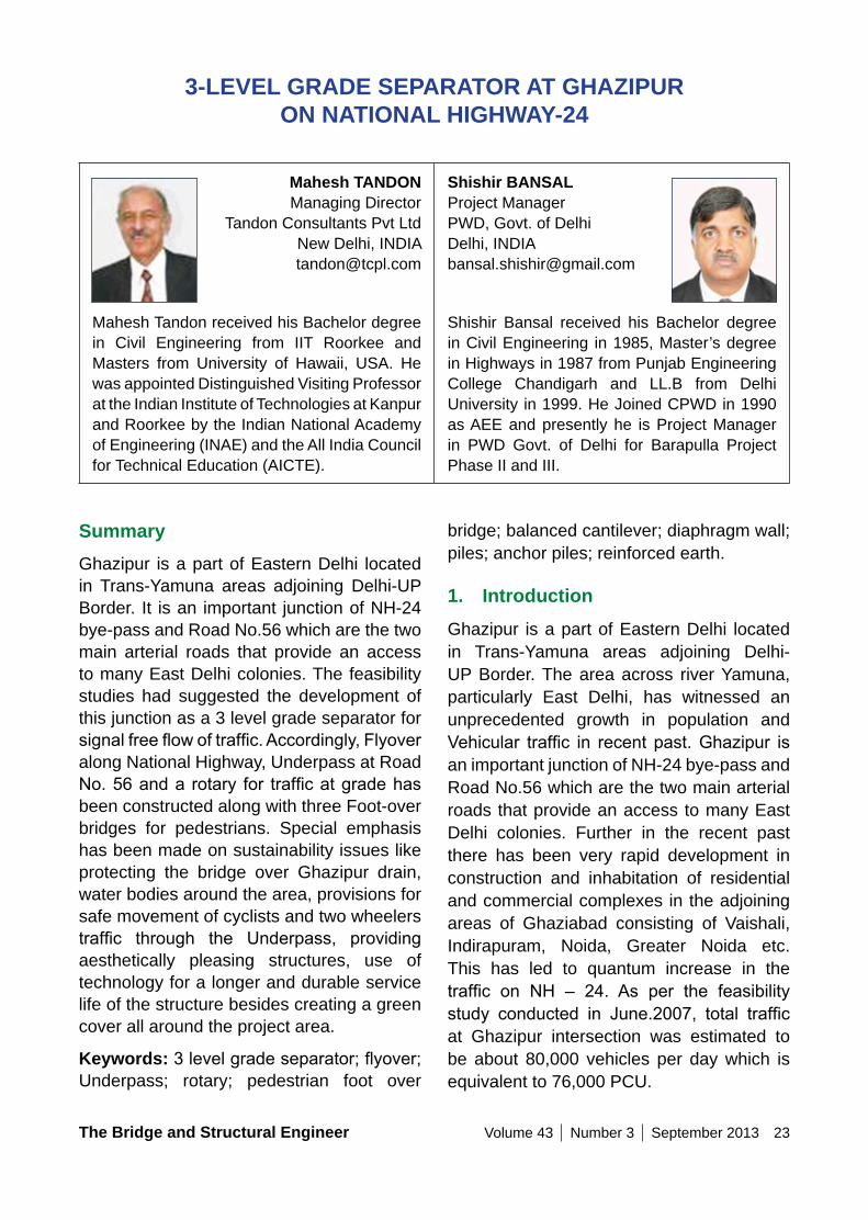
SummaryGhazipur is a part of Eastern Delhi located in Trans-Yamuna areas adjoining Delhi-UP Border. It is an important junction of NH-24 bye-pass and Road No.56 which are the two main arterial roads that provide an access to many East Delhi colonies. The feasibility studies had suggested the development of this junction as a 3 level grade separator for signalfreeflowoftraffic.Accordingly,Flyoveralong National Highway, Underpass at Road No.56anda rotary for trafficatgradehasbeen constructed along with three Foot-over bridges for pedestrians. Special emphasis has been made on sustainability issues like protecting the bridge over Ghazipur drain, water bodies around the area, provisions for safe movement of cyclists and two wheelers traffic through the Underpass, providingaesthetically pleasing structures, use of technology for a longer and durable service life of the structure besides creating a green cover all around the project area.
Keywords: 3levelgradeseparator;flyover;Underpass; rotary; pedestrian foot over
3-LEVEL GRADE SEPARAToR AT GHAzIPUR on nATIonAL HIGHWAy-24
Mahesh TAnDon Managing Director
Tandon Consultants Pvt Ltd New Delhi, INDIA [email protected]
Mahesh Tandon received his Bachelor degree in Civil Engineering from IIT Roorkee and Masters from University of Hawaii, USA. He was appointed Distinguished Visiting Professor at the Indian Institute of Technologies at Kanpur and Roorkee by the Indian National Academy of Engineering (INAE) and the All India Council for Technical Education (AICTE).
Shishir BAnSAL Project Manager PWD, Govt. of Delhi Delhi, INDIA [email protected]
Shishir Bansal received his Bachelor degree in Civil Engineering in 1985, Master’s degree in Highways in 1987 from Punjab Engineering College Chandigarh and LL.B from Delhi University in 1999. He Joined CPWD in 1990 as AEE and presently he is Project Manager in PWD Govt. of Delhi for Barapulla Project Phase II and III.
bridge; balanced cantilever; diaphragm wall; piles; anchor piles; reinforced earth.
1. IntroductionGhazipur is a part of Eastern Delhi located in Trans-Yamuna areas adjoining Delhi-UP Border. The area across river Yamuna, particularly East Delhi, has witnessed an unprecedented growth in population and Vehicular traffic in recent past.Ghazipur isan important junction of NH-24 bye-pass and Road No.56 which are the two main arterial roads that provide an access to many East Delhi colonies. Further in the recent past there has been very rapid development in construction and inhabitation of residential and commercial complexes in the adjoining areas of Ghaziabad consisting of Vaishali, Indirapuram, Noida, Greater Noida etc. This has led to quantum increase in the traffic on NH – 24. As per the feasibilitystudy conducted in June.2007, total trafficat Ghazipur intersection was estimated to be about 80,000 vehicles per day which is equivalent to 76,000 PCU.
24 Volume 43 Number 3 September 2013 The Bridge and Structural Engineer
2.1 Facilities created for the public including motorist, cyclists as well as pedestrians:
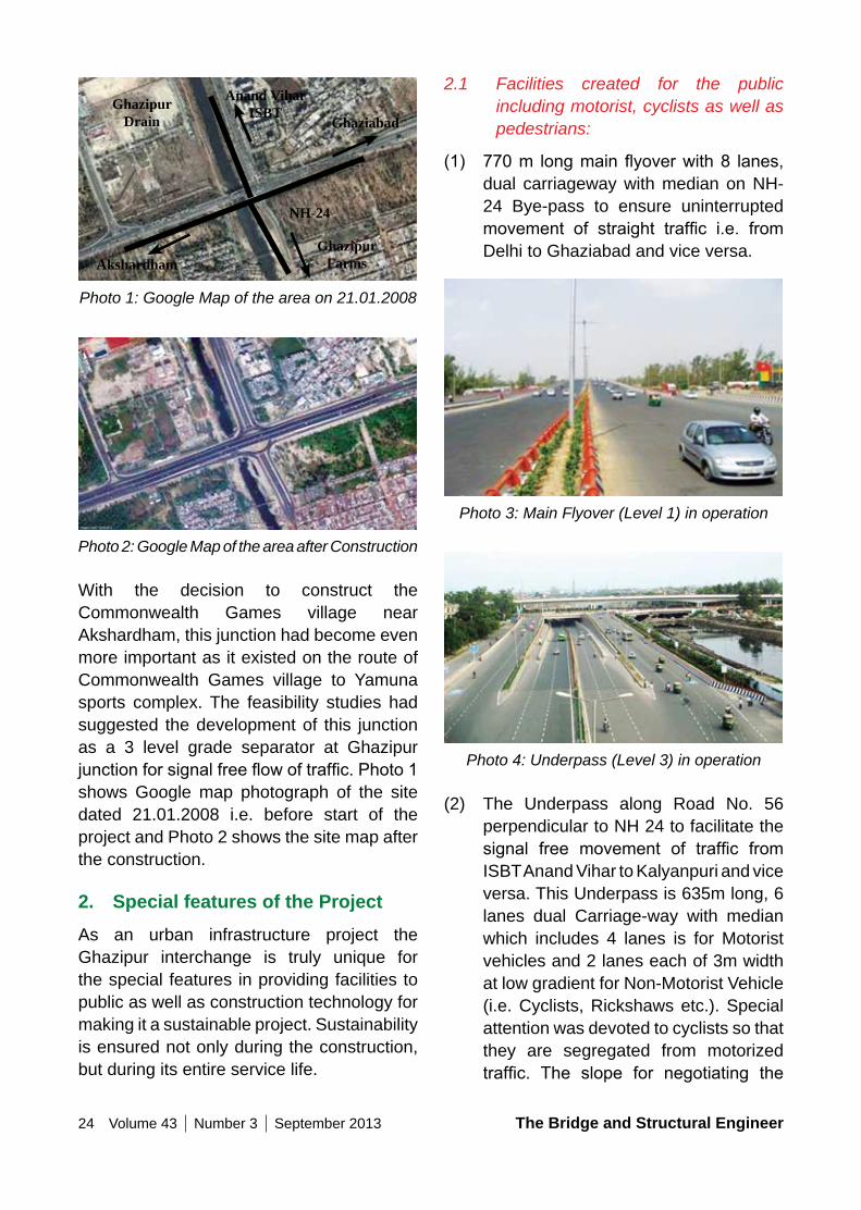
(1) 770m longmainflyoverwith8 lanes,dual carriageway with median on NH-24 Bye-pass to ensure uninterrupted movement of straight traffic i.e. fromDelhi to Ghaziabad and vice versa.
Photo 3: Main Flyover (Level 1) in operation
Photo 4: Underpass (Level 3) in operation
(2) The Underpass along Road No. 56 perpendicular to NH 24 to facilitate the signal free movement of traffic fromISBT Anand Vihar to Kalyanpuri and vice versa. This Underpass is 635m long, 6 lanes dual Carriage-way with median which includes 4 lanes is for Motorist vehicles and 2 lanes each of 3m width at low gradient for Non-Motorist Vehicle (i.e. Cyclists, Rickshaws etc.). Special attention was devoted to cyclists so that they are segregated from motorized traffic. The slope for negotiating the
Ghazipur Drain
Anand Vihar ISBT
NH-24
AkshardhamGhazipur
Farms
Ghaziabad
Photo 1: Google Map of the area on 21.01.2008
Photo 2: Google Map of the area after Construction
With the decision to construct the Commonwealth Games village near Akshardham, this junction had become even more important as it existed on the route of Commonwealth Games village to Yamuna sports complex. The feasibility studies had suggested the development of this junction as a 3 level grade separator at Ghazipur junctionforsignalfreeflowoftraffic.Photo1shows Google map photograph of the site dated 21.01.2008 i.e. before start of the project and Photo 2 shows the site map after the construction.
2. Special features of the ProjectAs an urban infrastructure project the Ghazipur interchange is truly unique for the special features in providing facilities to public as well as construction technology for making it a sustainable project. Sustainability is ensured not only during the construction, but during its entire service life.
The Bridge and Structural Engineer Volume 43 Number 3 September 2013 25
have to be on critical path for the overall success of the project.
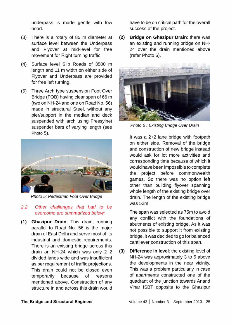
(2) Bridge on Ghazipur Drain: there was an existing and running bridge on NH-24 over the drain mentioned above (refer Photo 6).
Photo 6 : Existing Bridge Over Drain
It was a 2+2 lane bridge with footpath on either side. Removal of the bridge and construction of new bridge instead would ask for lot more activities and corresponding time because of which it would have been impossible to complete the project before commonwealth games. So there was no option left other than building flyover spanningwhole length of the existing bridge over drain. The length of the existing bridge was 52m.
The span was selected as 75m to avoid any conflict with the foundations ofabutments of existing bridge. As it was not possible to support it from existing bridge, it was decided to go for balanced cantilever construction of this span.
(3) Difference in level: the existing level of NH-24 was approximately 3 to 5 above the developments in the near vicinity. This was a problem particularly in case of apartments constructed one of the quadrant of the junction towards Anand Vihar ISBT opposite to the Ghazipur
underpass is made gentle with low head.
(3) There is a rotary of 85 m diameter at surface level between the Underpass and Flyover at mid-level for free movementforRightturningtraffic.
(4) Surface level Slip Roads of 3500 m length and 11 m width on either side of Flyover and Underpass are provided for free left turning.
(5) Three Arch type suspension Foot Over Bridge (FOB) having clear span of 66 m (two on NH-24 and one on Road No. 56) made in structural Steel, without any pier/support in the median and deck suspended with arch using Fressyinet suspender bars of varying length (see Photo 5).
Photo 5: Pedestrian Foot Over Bridge
2.2 Other challenges that had to be overcome are summarized below:
(1) Ghazipur Drain: This drain, running parallel to Road No. 56 is the major drain of East Delhi and serve most of its industrial and domestic requirements. There is an existing bridge across this drain on NH-24 which was only 2+2 dividedlaneswideandwasinsufficientasperrequirementoftrafficprojections.This drain could not be closed even temporarily because of reasons mentioned above. Construction of any structure in and across this drain would
26 Volume 43 Number 3 September 2013 The Bridge and Structural Engineer
road No. 56 and Kalyanpuri and towers along with one 11KV line of BSES.
3. Design Concept of Various Components
The design concept had to cater for existing features at the site which resulted in unequal span arrangements. Economy of the project was a major consideration, which also had to incorporate a 75 m span, amongst the largest inDelhiforbridges,flyovers,metro,etc.
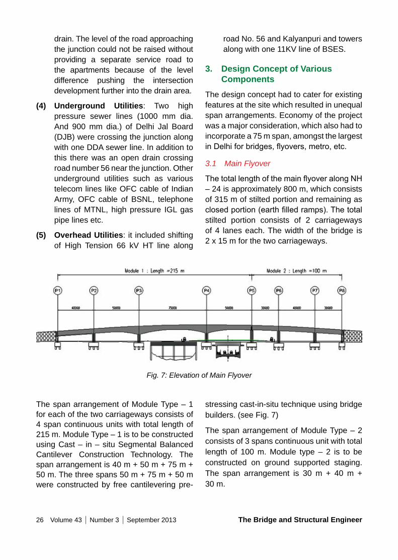
3.1 Main Flyover
ThetotallengthofthemainflyoveralongNH– 24 is approximately 800 m, which consists of 315 m of stilted portion and remaining as closedportion(earthfilledramps).Thetotalstilted portion consists of 2 carriageways of 4 lanes each. The width of the bridge is 2 x 15 m for the two carriageways.
drain. The level of the road approaching the junction could not be raised without providing a separate service road to the apartments because of the level difference pushing the intersection development further into the drain area.
(4) Underground Utilities: Two high pressure sewer lines (1000 mm dia. And 900 mm dia.) of Delhi Jal Board (DJB) were crossing the junction along with one DDA sewer line. In addition to this there was an open drain crossing road number 56 near the junction. Other underground utilities such as various telecom lines like OFC cable of Indian Army, OFC cable of BSNL, telephone lines of MTNL, high pressure IGL gas pipe lines etc.
(5) overhead Utilities: it included shifting of High Tension 66 kV HT line along
Fig. 7: Elevation of Main Flyover
The span arrangement of Module Type – 1 for each of the two carriageways consists of 4 span continuous units with total length of 215 m. Module Type – 1 is to be constructed using Cast – in – situ Segmental Balanced Cantilever Construction Technology. The span arrangement is 40 m + 50 m + 75 m + 50 m. The three spans 50 m + 75 m + 50 m were constructed by free cantilevering pre-
stressing cast-in-situ technique using bridge builders. (see Fig. 7)
The span arrangement of Module Type – 2 consists of 3 spans continuous unit with total length of 100 m. Module type – 2 is to be constructed on ground supported staging. The span arrangement is 30 m + 40 m + 30 m.
The Bridge and Structural Engineer Volume 43 Number 3 September 2013 27
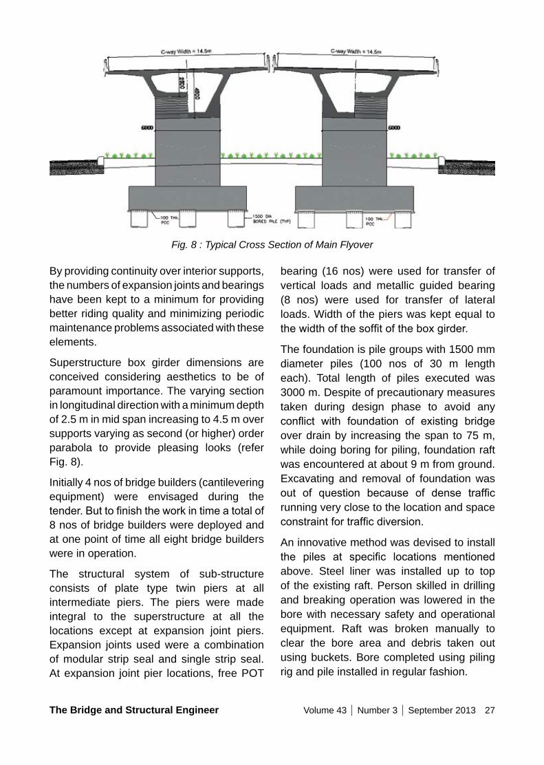
Fig. 8 : Typical Cross Section of Main Flyover
By providing continuity over interior supports, the numbers of expansion joints and bearings have been kept to a minimum for providing better riding quality and minimizing periodic maintenance problems associated with these elements.
Superstructure box girder dimensions are conceived considering aesthetics to be of paramount importance. The varying section in longitudinal direction with a minimum depth of 2.5 m in mid span increasing to 4.5 m over supports varying as second (or higher) order parabola to provide pleasing looks (refer Fig. 8).
Initially 4 nos of bridge builders (cantilevering equipment) were envisaged during the tender.Buttofinishtheworkintimeatotalof8 nos of bridge builders were deployed and at one point of time all eight bridge builders were in operation.
The structural system of sub-structure consists of plate type twin piers at all intermediate piers. The piers were made integral to the superstructure at all the locations except at expansion joint piers. Expansion joints used were a combination of modular strip seal and single strip seal. At expansion joint pier locations, free POT
bearing (16 nos) were used for transfer of vertical loads and metallic guided bearing (8 nos) were used for transfer of lateral loads. Width of the piers was kept equal to thewidthofthesoffitoftheboxgirder.
The foundation is pile groups with 1500 mm diameter piles (100 nos of 30 m length each). Total length of piles executed was 3000 m. Despite of precautionary measures taken during design phase to avoid any conflict with foundation of existing bridgeover drain by increasing the span to 75 m, while doing boring for piling, foundation raft was encountered at about 9 m from ground. Excavating and removal of foundation was out of question because of dense trafficrunning very close to the location and space constraintfortrafficdiversion.
An innovative method was devised to install the piles at specific locations mentionedabove. Steel liner was installed up to top of the existing raft. Person skilled in drilling and breaking operation was lowered in the bore with necessary safety and operational equipment. Raft was broken manually to clear the bore area and debris taken out using buckets. Bore completed using piling rig and pile installed in regular fashion.
28 Volume 43 Number 3 September 2013 The Bridge and Structural Engineer
Crash barrier provided was a combination ofprecastfascia(withformlinerfinish)andcastinsituportiontoripethebenefitofbetterfinish quality of casting in yard and betterstructural integrity of in situ construction.
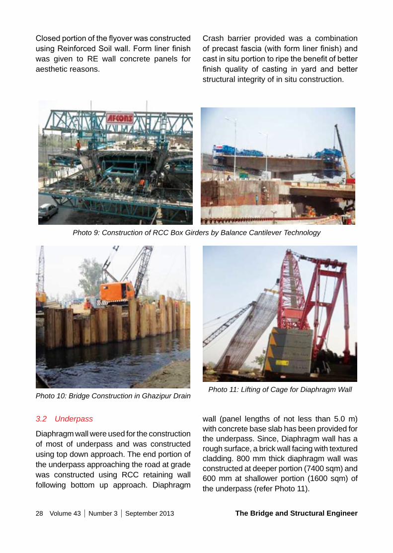
ClosedportionoftheflyoverwasconstructedusingReinforcedSoilwall.Formlinerfinishwas given to RE wall concrete panels for aesthetic reasons.
Photo 9: Construction of RCC Box Girders by Balance Cantilever Technology
Photo 10: Bridge Construction in Ghazipur DrainPhoto 11: Lifting of Cage for Diaphragm Wall
3.2 Underpass
Diaphragm wall were used for the construction of most of underpass and was constructed using top down approach. The end portion of the underpass approaching the road at grade was constructed using RCC retaining wall following bottom up approach. Diaphragm
wall (panel lengths of not less than 5.0 m) with concrete base slab has been provided for the underpass. Since, Diaphragm wall has a rough surface, a brick wall facing with textured cladding. 800 mm thick diaphragm wall was constructed at deeper portion (7400 sqm) and 600 mm at shallower portion (1600 sqm) of the underpass (refer Photo 11).
The Bridge and Structural Engineer Volume 43 Number 3 September 2013 29
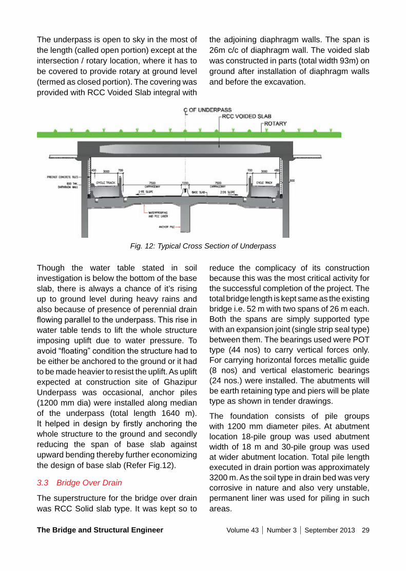
the adjoining diaphragm walls. The span is 26m c/c of diaphragm wall. The voided slab was constructed in parts (total width 93m) on ground after installation of diaphragm walls and before the excavation.
The underpass is open to sky in the most of the length (called open portion) except at the intersection / rotary location, where it has to be covered to provide rotary at ground level (termed as closed portion). The covering was provided with RCC Voided Slab integral with
Fig. 12: Typical Cross Section of Underpass
Though the water table stated in soil investigation is below the bottom of the base slab, there is always a chance of it’s rising up to ground level during heavy rains and also because of presence of perennial drain flowingparalleltotheunderpass.Thisriseinwater table tends to lift the whole structure imposing uplift due to water pressure. To avoid“floating”conditionthestructurehadtobe either be anchored to the ground or it had to be made heavier to resist the uplift. As uplift expected at construction site of Ghazipur Underpass was occasional, anchor piles (1200 mm dia) were installed along median of the underpass (total length 1640 m). It helped in design by firstly anchoring thewhole structure to the ground and secondly reducing the span of base slab against upward bending thereby further economizing the design of base slab (Refer Fig.12).
3.3 Bridge Over Drain
The superstructure for the bridge over drain was RCC Solid slab type. It was kept so to
reduce the complicacy of its construction because this was the most critical activity for the successful completion of the project. The total bridge length is kept same as the existing bridge i.e. 52 m with two spans of 26 m each. Both the spans are simply supported type with an expansion joint (single strip seal type) between them. The bearings used were POT type (44 nos) to carry vertical forces only. For carrying horizontal forces metallic guide (8 nos) and vertical elastomeric bearings (24 nos.) were installed. The abutments will be earth retaining type and piers will be plate type as shown in tender drawings.
The foundation consists of pile groups with 1200 mm diameter piles. At abutment location 18-pile group was used abutment width of 18 m and 30-pile group was used at wider abutment location. Total pile length executed in drain portion was approximately 3200 m. As the soil type in drain bed was very corrosive in nature and also very unstable, permanent liner was used for piling in such areas.
30 Volume 43 Number 3 September 2013 The Bridge and Structural Engineer
4.1 Air Pollution
Construction activities that contribute to air pollution include land clearing, operation of diesel engines and demolitions.
(1) Earthworkexcavation,refilling,handlingand transportation of construction materials (like sand and aggregate), and construction of earthen ramps produce large volumes of dust if it is not done properly. This dust can carry for large distances over a long period of time.
(2) Another major source of PM10 observed on construction site is the diesel engine exhausts of vehicles and heavy equipment known as diesel particulate matter (DPM) and consists of sulphate and silicates, all of which readily combine with other toxins in the atmosphere, increasing the health risks of particle inhalation.
In the Ghazipur project, complete care was taken to avoid any dusty environment during excavations or carrying the building materials to site. This has been achieved by covering the trucks carrying construction material, frequent sprinkling of water all round so as to settle the dust and does not pollute the environment. All the vehicles used were essentially to undergo pollution test at prescribe frequency so that it does not emit any harmful gases in the environment.
4.2 Water Pollution
Sources of water pollution on building sites include diesel/ oil, paints, cleaners, other harmful chemicals and construction debris/dirt. When land is cleared, it causes soil erosion that runs into natural waterways turns them turbid and when runs into the nearby drainage system cause silting of drains. In the instant case a city drain is passing nearby which has a potential of getting silted or choked.
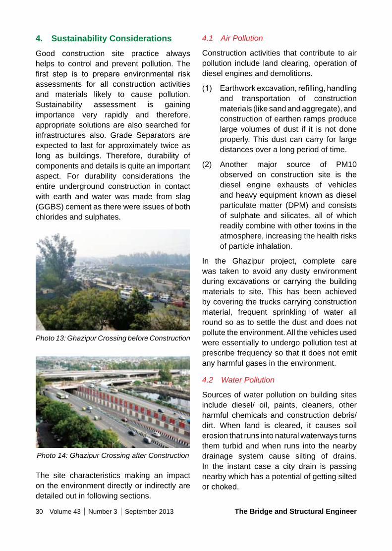
4. Sustainability ConsiderationsGood construction site practice always helps to control and prevent pollution. The first step is to prepare environmental riskassessments for all construction activities and materials likely to cause pollution. Sustainability assessment is gaining importance very rapidly and therefore, appropriate solutions are also searched for infrastructures also. Grade Separators are expected to last for approximately twice as long as buildings. Therefore, durability of components and details is quite an important aspect. For durability considerations the entire underground construction in contact with earth and water was made from slag (GGBS) cement as there were issues of both chlorides and sulphates.
Photo 13: Ghazipur Crossing before Construction
Photo 14: Ghazipur Crossing after Construction
The site characteristics making an impact on the environment directly or indirectly are detailed out in following sections.
The Bridge and Structural Engineer Volume 43 Number 3 September 2013 31
DJB, 900 mm dia sewer line of DDA, 1000 mm dia storm water drain of DDA, 900 mm dia water pipe line, 300 mm dia water pipe line on slip road No. 7, OFC cable of Indian Army, OFC cable of BSNL, Telephone lines of MTNL. Safe corridors were assigned to all the departments for shifting their utilities in a professional manner.
4.4 Noise Pollution
Construction sites produce a lot of vibration and noise, mainly from vehicles, heavy equipment and machinery, excavation for casting piles, braking up pile heads, road surface but also from people shouting and radios turned up too loud. Excessive noise is not only annoying and distracting, but also lead to sleep disturbance and extreme stress.
In this project, noise pollution was reduced through careful handling of materials, use of modern, quiet power tools, equipment and silent generators. Noise generating activities are avoided in the night and work programme is planned properly so that any particularly noisy activities can be scheduled to avoid sensitive times. Modern vehicles and machinery are utilized with the requisite adaptations to limit noise and exhaust emissions and ensuring that these are maintained tomanufacturers’ specificationsat all times.
4.5 Social Factors
The disturbance caused to the public residing in vicinity of Ghazipur Project is given due regard and the inconvenience of any kind or sudden disturbance on their life style due to taking up of any project in their vicinity is an given due consideration. Large scale disturbancetomovingtrafficcausedduetoconstruction activities at site as well as off side in casting yard like carrying of RMC is carried out only in late hours. Workers and public at construction site as well as the public at
In the Ghazipur grade separator, a city drain coming from Shahadra is passing through the project site.
While designing the project, all care was taken to place the foundation system so as not to interfere with the drainage system. Further, the drain was protected from any kind of site disposals. Waste generated from the site was ensured to be dumped at a safe place rather than dropping them consciously or unconsciously in the drain.
The existing water body was incorporated in the overall landscaping which greatly enhanced the aesthetics of the project (Refer Photo 4).
4.3 Land Pollution
Construction activities that contribute to land pollution include uprooting of trees, excavation of foundations, land clearing. Excavation produces large quantity of waste soil, which needs proper disposal. This however is utilized in construction earthen ramps, so that the surplus soil that requires proper disposal is minimal. During deep excavation for pile foundation, water gets collected in the void, needing disposal. Indiscriminate disposal of this silt – laden water may choke drains, lead to water accumulation etc. Also, existing drains in the ROW gets disturbed. Excavation has a potential of causing damage to the existing infrastructure/utilities. There is always number of various utilities like electric poles, transformers, water lines, drainage lines, Telephone cables, Gas lines etc. within the ROW, which needs to be relocated.
In the Ghazipur grade separator Project, number of utilities were to be shifted from the existing locations which includes, IGL gas pipe line, 66 KV HT line along road No. 56 and Kalyanpuri, 66 KV HT line along NH-24, 11 KV line of BSES, 1000 mm dia sewer line of DJB, 900 mm dia. sewer line of
32 Volume 43 Number 3 September 2013 The Bridge and Structural Engineer
awards for its innovative design and construction features and for enhancing the quality of the built environment:
• Institute for Steel Development & Growth Award - Foot over Bridge at 3-Level Grade Separator at Ghazipur Intersection, New Delhi - 2013.
• Construction Industry Development Council (Vishwakarma Award) - Grade Separator at Ghazipur on NH-24 - 2012.
• Central Public Works Department – Best Infrastructure Project completed in 2011-2012.
6. Discussions and Conclusions(1) It is true that civil constructions in
urban areas are essential for overall development and benefits of thecommunity, but same is successful only if equal importance is given to the environment and it is given due care for a sustainable development.
(2) It is essential that every construction activity should be environment friendly as the Environment too has a right to remain protected. Engineering solutions to minimize the Environment impacts and for adopting the mitigation measures are available.
(3) Adoption of standard and safe construction practices is very much essential particularly in urban environment. It must be ensured in all times that all workers adopt best safety protections in their own interest. Protection of Health, Safety and Environment should always be kept as the prime goal.
(4) The right of respectful living of the residents residing around the construction sites should not be
large passing nearby the construction sites in Urban Environment are given due protection from the risk of accidents. No single accident was recorded during the concurrency of the project.
4.6 Safety Measures for workers and public
(1) Being an artery on National Highway with high volumes of traffic forconnection to Ghazipur, Noida and other NCT areas, it was essential to evolve structural schemes and trafficdiversion scheme so that at no time the trafficisinconvenienced.
(2) Standard and safe construction practices were strictly followed. Entire construction area that was under influence in case of accidents isbarricaded properly. This is particularly critical during the usage of heavy duty cranes. These activities are conducted duringleantrafficperiodsandifrequiredtrafficisalsostopped.Accidentalentryoftraffic(pedestrian/vehicular)intositeis avoided. Warning boards/sign boards and post security guards are provided throughout the day and night.
(3) It was ensured that all workers are provided with and use appropriate Personal Protective Equipment like helmet, hand gloves, boots, masks, safety hoists when working at height or in foul conditions, etc.
(4) Standard practices of safety checks as prescribed were followed before use of equipment such as cranes, hoists, etc. Environmental, Health and Safety (EHS) Expert was employed at site. Health and Safety Training for all site personnel was provided at site.
5. AwardsThis project has received the following
The Bridge and Structural Engineer Volume 43 Number 3 September 2013 33
9. References1. BANSAL S., GUPTA V., S K SINGH
“A 3-Level Grade-Separator at Ghazipur in East Delhi and sustainability considerations during the construction”, proceedings of international seminar on “Emerging Trends in Transportation Structures” IIBE, 24th to 25th November 2012, Mumbai, India.
2. BANSAL S., SINGH S.K., KURIAN J., “Application of Environmental Friendly Systems to protect the Environment during construction of Grade Separators in New Delhi, proceedings of 1ST International Conference on Concrete Sustainability, JCI, 27th to 29th May 2013 at Tokyo, Japan
3. TANDON, Mahesh, “Bridges and Flyovers for Commonwealth Games 2010” Proceedings of Ukeri Concrete Congress, Innovations in Concrete Construction, Jalandhar 5-8 Mar 2013.
4. TANDON, Mahesh, “Infrastructure Projects for Commonwealth Games 2010”. State of the Art lecture at Institution of Engineers (India), Roorkee 12-14 October, 2012.
5. TANDON, Mahesh, “Sustainability in Urban Infrastructure Projects”. Structural Engineering Convention 2012, S.V.N.I.T. Surat.
jeopardized. This should be given due consideration without compromising on their comforts, safe movements and safe livelihood.
7. Acknowledgement
The authors would like to express their sincere thanks to Er. Deepak Panwar, Project Manager and Er. S C Chauhan, Executive Engineer for providing the required data of Ghazipur Flyover and Environment related issues required for concluding this paper. The authors would also like to express their sincere thanks to Public Works Department, Govt. of Delhi for providing the necessary information available and necessary in concluding the paper in the required shape.
8. Credits
• Contractor : M/s AFCONS Infrastructures Ltd.
• Geometric : M/s TPA Consultant Consultancy India
Private Ltd.
• Proof Consultant : M/s Construma Consultancy Private Ltd.
• Prime Consultant : M/s Tandon Consultant Private Ltd
34 Volume 43 Number 3 September 2013 The Bridge and Structural Engineer
SummarySalient design and construction features of one of the most complex three level grade separator ever constructed in the city of Delhi is presented in this paper. The Grade Separator comprises of the following major structural components:
• A 6 lane flyover at Apsara Border along the GT Road
• Two 2 lane Underpasses along Road No. 56 and Road No. 62
• Two RUBs constructed under extremely challenging conditions by using box pushing technique
• Two Foot Over Bridges across Road No. 56 and Road No. 62
• Widening of existing bridge over Major Drain & Allied Works
This is one of the rare project with several unique features requiring creative and innovative solutions. This is the first project in India where contiguous piles in
DESIGn & ConSTRUCTIon oF GRADE SEPARAToR nEAR APSARA BoRDER, DELHI
Alok BHoWMICK Managing Director B&S Engineering Consultants Pvt Ltd Delhi [email protected]
Alok Bhowmick, born 1959, graduated in Civil Engineering from Delhi University in 1981 and did his post graduation from IIT, Delhi in 1992. He has to his credit a number of major design projects in PSC, RCC and Structural Steel in India & overseas. The highlights of his carrier spanning more than 32 years include the design of notable structures in various parts of India and overseas. MrBhowmickhasmadesignificantcontributionsinthefieldofstructuralengineeringbothwithinand outside his organization by sharing his expertise and experience. He is an active member of several technical committees of Indian Roads Congress. He is a fellow member of governing council of Indian Association of Structural Engineers.
combination with prestressed horizontal ties have been successfully used for supporting the existing ROB approach close to the proposed Underpass. This grade separator also claims to have the longest total length of Underpass constructed in Delhi (total length 1666 m). The project is recipient of CIDC-Vishwakarma Award 2012 under the category “Best Project”. The project is also recipient of ICI-NDC award for “Best Concrete Structure in Delhi” for the year 2011.
Key Words: Grade Separator, Superstructure, Pile Foundation, Soil Anchor, Box Pushing, Underpass, Foot Over Bridge, Prestressed Tie
1. IntroductionThe need for a grade separator at the Seemapuri Border near Apsara Talkies, Delhi was felt for more than two decades, before it was actually constructed. Long queues at the intersection, frequent trafficjams for hours were a common sight at this intersection. Public Works Department,
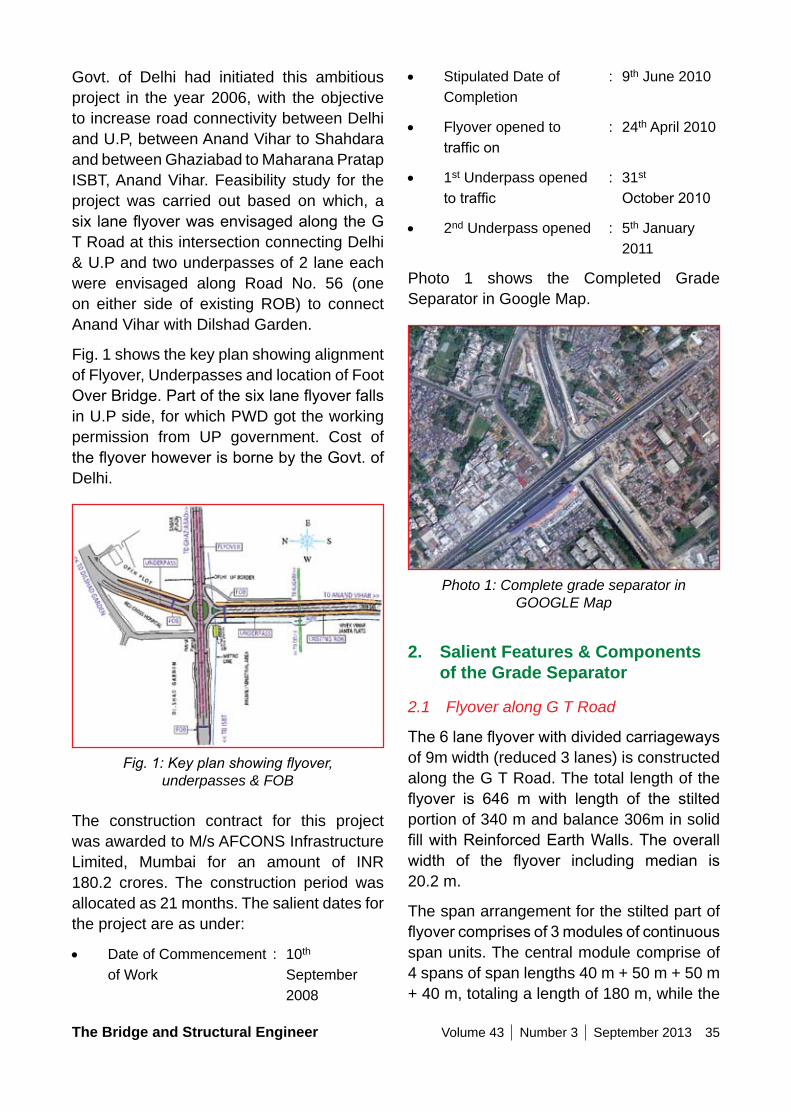
The Bridge and Structural Engineer Volume 43 Number 3 September 2013 35
• Stipulated Date of : 9th June 2010 Completion
• Flyover opened to : 24th April 2010 trafficon
• 1st Underpass opened : 31st totraffic October2010
• 2nd Underpass opened : 5th January 2011
Photo 1 shows the Completed Grade Separator in Google Map.
Photo 1: Complete grade separator in GOOGLE Map
2. Salient Features & Components of the Grade Separator
2.1 Flyover along G T Road
The6laneflyoverwithdividedcarriagewaysof 9m width (reduced 3 lanes) is constructed along the G T Road. The total length of the flyover is 646 m with length of the stiltedportion of 340 m and balance 306m in solid fillwithReinforcedEarthWalls.Theoverallwidth of the flyover including median is20.2 m.
The span arrangement for the stilted part of flyovercomprisesof3modulesofcontinuousspan units. The central module comprise of 4 spans of span lengths 40 m + 50 m + 50 m + 40 m, totaling a length of 180 m, while the
Govt. of Delhi had initiated this ambitious project in the year 2006, with the objective to increase road connectivity between Delhi and U.P, between Anand Vihar to Shahdara and between Ghaziabad to Maharana Pratap ISBT, Anand Vihar. Feasibility study for the project was carried out based on which, a sixlaneflyoverwasenvisagedalongtheGT Road at this intersection connecting Delhi & U.P and two underpasses of 2 lane each were envisaged along Road No. 56 (one on either side of existing ROB) to connect Anand Vihar with Dilshad Garden.
Fig. 1 shows the key plan showing alignment of Flyover, Underpasses and location of Foot OverBridge.Partofthesixlaneflyoverfallsin U.P side, for which PWD got the working permission from UP government. Cost of theflyoverhoweverisbornebytheGovt.ofDelhi.
Fig. 1: Key plan showing flyover, underpasses & FOB
The construction contract for this project was awarded to M/s AFCONS Infrastructure Limited, Mumbai for an amount of INR 180.2 crores. The construction period was allocated as 21 months. The salient dates for the project are as under:
• Date of Commencement : 10th of Work September
2008
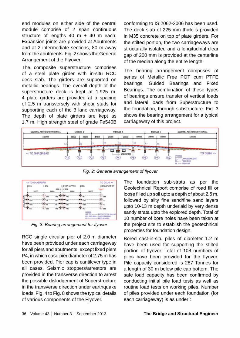
36 Volume 43 Number 3 September 2013 The Bridge and Structural Engineer
conforming to IS:2062-2006 has been used. The deck slab of 225 mm thick is provided in M35 concrete on top of plate girders. For the stilted portion, the two carriageways are structurally isolated and a longitudinal clear gap of 200 mm is provided at the centerline of the median along the entire length.
The bearing arrangement comprises of series of Metallic Free POT cum PTFE bearings, Guided Bearings and Fixed Bearings. The combination of these types of bearings ensure transfer of vertical loads and lateral loads from Superstructure to the foundation, through substructure. Fig. 3 shows the bearing arrangement for a typical carriageway of this project.
end modules on either side of the central module comprise of 2 span continuous structure of lengths 40 m + 40 m each. Expansion joints are provided at Abutments and at 2 intermediate sections, 80 m away from the abutments. Fig. 2 shows the General Arrangement of the Flyover.The composite superstructure comprises of a steel plate girder with in-situ RCC deck slab. The girders are supported on metallic bearings. The overall depth of the superstructure deck is kept at 1.925 m. 4 plate girders are provided at a spacing of 2.5 m transversely with shear studs for supporting each of the 3 lane carriageway. The depth of plate girders are kept as 1.7 m. High strength steel of grade Fe540B
Fig. 2: General arrangement of flyover
Fig. 3: Bearing arrangement for flyover
RCC single circular pier of 2.0 m diameter have been provided under each carriageway forallpiersandabutments,exceptfixedpiersP4, in which case pier diameter of 2.75 m has been provided. Pier cap is cantilever type in all cases. Seismic stoppers/arrestors are provided in the transverse direction to arrest the possible dislodgement of Superstructure in the transverse direction under earthquake loads. Fig. 4 to Fig. 8 shows the typical details of various components of the Flyover.
The foundation sub-strata as per the GeotechnicalReportcompriseof roadfillorloosefilledupsoiluptoadepthofabout2.5m,followed by silty fine sand/fine sand layersupto 10-13 m depth underlaid by very dense sandy strata upto the explored depth. Total of 10 number of bore holes have been taken at the project site to establish the geotechnical properties for foundation design.
Bored cast-in-situ piles of diameter 1.2 m have been used for supporting the stilted portion of flyover. Total of 108 numbers ofpiles have been provided for the flyover.Pile capacity considered is 287 Tonnes for a length of 30 m below pile cap bottom. The safe load capacity has been confirmed byconducting initial pile load tests as well as routine load tests on working piles. Number of piles provided under each foundation (for each carriageway) is as under :
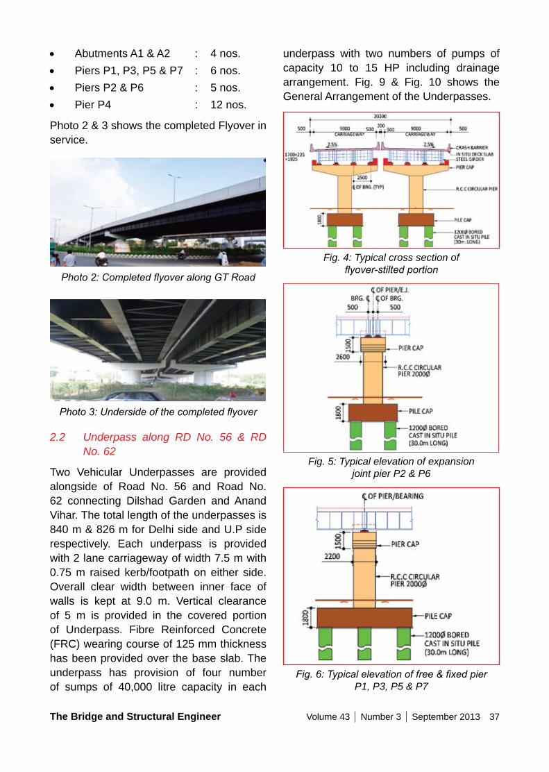
The Bridge and Structural Engineer Volume 43 Number 3 September 2013 37
underpass with two numbers of pumps of capacity 10 to 15 HP including drainage arrangement. Fig. 9 & Fig. 10 shows the General Arrangement of the Underpasses.
Fig. 4: Typical cross section of flyover-stilted portion
Fig. 5: Typical elevation of expansion joint pier P2 & P6
Fig. 6: Typical elevation of free & fixed pier P1, P3, P5 & P7
• Abutments A1 & A2 : 4 nos.• Piers P1, P3, P5 & P7 : 6 nos.• Piers P2 & P6 : 5 nos.• Pier P4 : 12 nos.
Photo 2 & 3 shows the completed Flyover in service.
Photo 2: Completed flyover along GT Road
Photo 3: Underside of the completed flyover
2.2 Underpass along RD No. 56 & RD No. 62
Two Vehicular Underpasses are provided alongside of Road No. 56 and Road No. 62 connecting Dilshad Garden and Anand Vihar. The total length of the underpasses is 840 m & 826 m for Delhi side and U.P side respectively. Each underpass is provided with 2 lane carriageway of width 7.5 m with 0.75 m raised kerb/footpath on either side. Overall clear width between inner face of walls is kept at 9.0 m. Vertical clearance of 5 m is provided in the covered portion of Underpass. Fibre Reinforced Concrete (FRC) wearing course of 125 mm thickness has been provided over the base slab. The underpass has provision of four number of sumps of 40,000 litre capacity in each
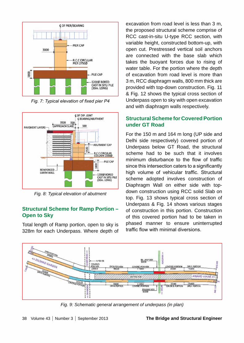
38 Volume 43 Number 3 September 2013 The Bridge and Structural Engineer
excavation from road level is less than 3 m, the proposed structural scheme comprise of RCC cast-in-situ U-type RCC section, with variable height, constructed bottom-up, with open cut. Prestressed vertical soil anchors are connected with the base slab which takes the buoyant forces due to rising of water table. For the portion where the depth of excavation from road level is more than 3 m, RCC diaphragm walls, 800 mm thick are provided with top-down construction. Fig. 11 & Fig. 12 shows the typical cross section of Underpass open to sky with open excavation and with diaphragm walls respectively.
Structural Scheme for Covered Portion under GT RoadFor the 150 m and 164 m long (UP side and Delhi side respectively) covered portion of Underpass below GT Road, the structural scheme had to be such that it involves minimum disturbance to the flow of trafficsincethisintersectioncaterstoasignificantlyhigh volume of vehicular traffic. Structuralscheme adopted involves construction of Diaphragm Wall on either side with top-down construction using RCC solid Slab on top. Fig. 13 shows typical cross section of Underpass & Fig. 14 shows various stages of construction in this portion. Construction of this covered portion had to be taken in phased manner to ensure uninterrupted trafficflowwithminimaldiversions.
Fig. 7: Typical elevation of fixed pier P4
Fig. 8: Typical elevation of abutment
Structural Scheme for Ramp Portion – open to SkyTotal length of Ramp portion, open to sky is 328m for each Underpass. Where depth of
Fig. 9: Schematic general arrangement of underpass (in plan)
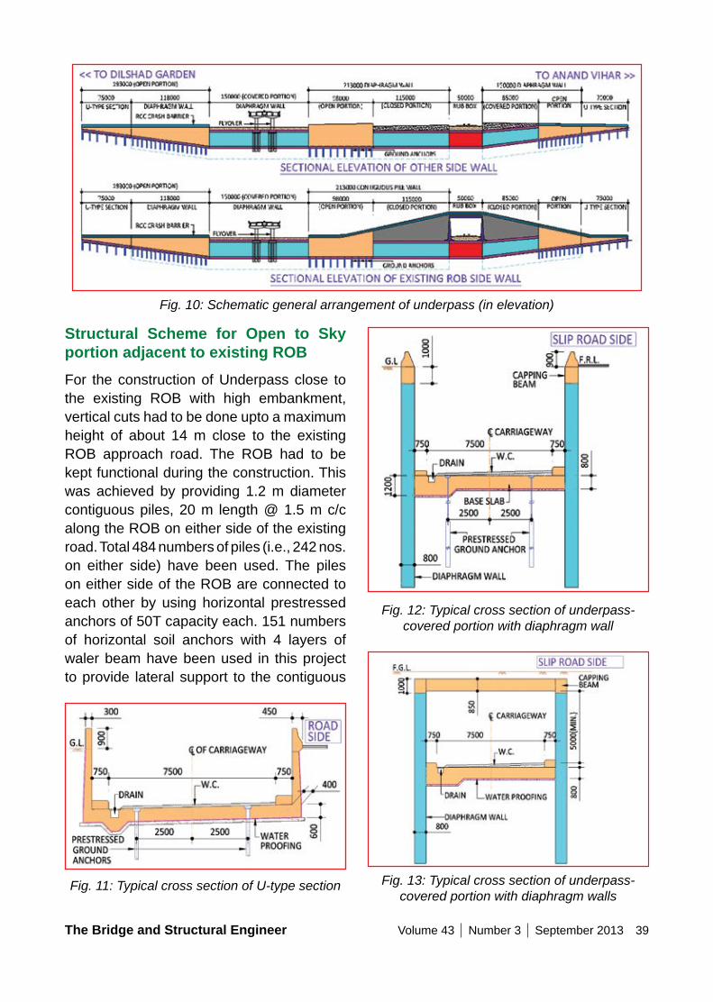
The Bridge and Structural Engineer Volume 43 Number 3 September 2013 39
Fig. 10: Schematic general arrangement of underpass (in elevation)
Structural Scheme for open to Sky portion adjacent to existing RoBFor the construction of Underpass close to the existing ROB with high embankment, vertical cuts had to be done upto a maximum height of about 14 m close to the existing ROB approach road. The ROB had to be kept functional during the construction. This was achieved by providing 1.2 m diameter contiguous piles, 20 m length @ 1.5 m c/c along the ROB on either side of the existing road. Total 484 numbers of piles (i.e., 242 nos. on either side) have been used. The piles on either side of the ROB are connected to each other by using horizontal prestressed anchors of 50T capacity each. 151 numbers of horizontal soil anchors with 4 layers of waler beam have been used in this project to provide lateral support to the contiguous
Fig. 11: Typical cross section of U-type section
Fig. 12: Typical cross section of underpass-covered portion with diaphragm wall
Fig. 13: Typical cross section of underpass-covered portion with diaphragm walls

40 Volume 43 Number 3 September 2013 The Bridge and Structural Engineer
ROB, the structural scheme proposed comprise of providing 1.2 m diameter RCC bored cast-in-situ contiguous piles @ 1.5 m c/c towards the existing ROB side, 800 mm thick RCC diaphragm walls on the other side. Excavation is done in a phased manner with application of horizontal prestressed anchors connecting the contiguous piles on either side of the existing ROB. Fig. 15 shows the typical cross section of Underpass open to sky adjacent to the existing ROB.
Structural Scheme for Covered portion adjacent to existing Rail LineFor the 200 m long covered portion of Underpass, located adjacent to the existing rail line, on either side of the rail line, the height of ROB approach embankment is maximum. The structural scheme proposed comprise of providing 1.2 m diameter RCC bored cast-in-situ contiguous piles, 20 m long @ 1.5 m c/c towards the existing ROB side, 800 mm thick RCC diaphragm walls on the other side of Underpass. Excavation is
piles for retaining the embankment of ROB approach with vertical cut. By retaining the earth with contiguous piles on ROB side, excavation for construction of underpass with vertical cut was possible, which helped in providing adequate working space as well in providing the thrust blocks for box pushing in the railway portion. Photo 4 shows the erection of waler beam over contiguous pile.
For the 98 m long open to sky portion of Underpass, located adjacent to the existing
Fig. 14: Construction sequence for covered underpass under GT road
Photo 4: Erection of waler beam over contiguous pile
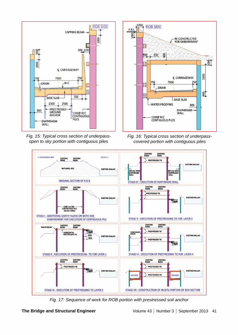
The Bridge and Structural Engineer Volume 43 Number 3 September 2013 41
Fig. 17: Sequence of work for ROB portion with prestressed soil anchor
Fig. 15: Typical cross section of underpass-open to sky portion with contiguous piles
Fig. 16: Typical cross section of underpass-covered portion with contiguous piles
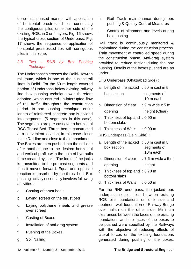
42 Volume 43 Number 3 September 2013 The Bridge and Structural Engineer
done in a phased manner with application of horizontal prestressed ties connecting the contiguous piles on either side of the existing ROB, in 3 or 4 layers. Fig. 16 shows the typical cross section of Underpass. Fig. 17 shows the sequence of application of horizontal prestressed ties with contiguous piles in this zone.
2.3 Two – RUB by Box Pushing Technique
The Underpasses crosses the Delhi-Howrah rail route, which is one of the busiest rail lines in Delhi. For the 50 m length covered portion of Underpass below existing railway line, box pushing technique was therefore adopted,whichensuredun-interruptedflowof rail traffic throughout the constructionperiod. In box pushing technique, entire length of reinforced concrete box is divided into segments (5 segments in this case). The segments are pre-cast over a horizontal RCC Thrust Bed. Thrust bed is constructed at a convenient location, in this case closer to the Rail line and close to the embankment. The Boxes are then pushed into the soil one after another one to the desired horizontal andverticalprofilewiththehelpofhydraulicforce created by jacks. The force of the jacks is transmitted to the pre-cast segments and thus it moves forward. Equal and opposite reaction is absorbed by the thrust bed. Box pushing activity essentially involves following activities :
a. Casting of thrust bed :
b. Laying screed on the thrust bed
c. Laying polythene sheets and grease over screed
d. Casting of Boxes
e. Installation of anti-drag system
f. Pushing of the Boxes
g. Soil Nailing
h. Rail Track maintenance during box pushing & Quality Control Measures
i. Control of alignment and levels during box pushing
Rail track is continuously monitored & maintained during the construction process. Train movement at controlled speed during the construction phase. Anti-drag system provided to reduce friction during the box pushing. Details of the boxes pushed are as under :
LHS Underpass (Ghaziabad Side) :
a. Length of the jacked : 50 m cast in 5 box section segments of
10 m eachb. Dimension of clear : 9 m wide x 5 m opening height (Clear)c. Thickness of top and : 0.90 m
bottom slabsd. Thickness of Walls : 0.90 mRHS Underpass (Delhi Side) :
a. Length of the jacked : 50 m cast in 5 box section segments of
10m eachb. Dimension of clear : 7.6 m wide x 5 m opening heightc. Thickness of top and : 0.70 m
bottom slabsd. Thickness of Walls : 0.50 m
For the RHS underpass, the jacked box underpass section lies between existing ROB pile foundations on one side and abutment well foundation of Railway Bridge over nallah on the other side. Minimum clearances between the faces of the existing foundations and the faces of the boxes to be pushedwere specified by theRailwayswith the objective of reducing effects of lateral forces on the existing foundations generated during pushing of the boxes.
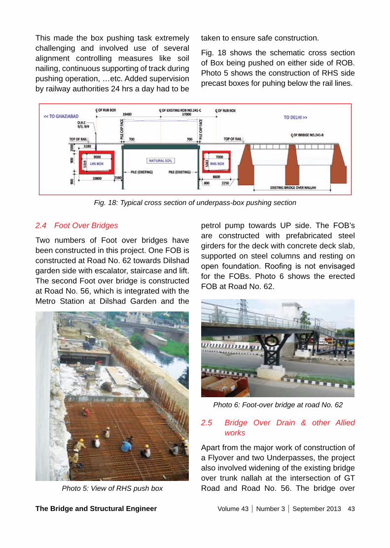
The Bridge and Structural Engineer Volume 43 Number 3 September 2013 43
taken to ensure safe construction.
Fig. 18 shows the schematic cross section of Box being pushed on either side of ROB. Photo 5 shows the construction of RHS side precast boxes for puhing below the rail lines.
This made the box pushing task extremely challenging and involved use of several alignment controlling measures like soil nailing, continuous supporting of track during pushing operation, …etc. Added supervision by railway authorities 24 hrs a day had to be
Fig. 18: Typical cross section of underpass-box pushing section
2.4 Foot Over Bridges
Two numbers of Foot over bridges have been constructed in this project. One FOB is constructed at Road No. 62 towards Dilshad garden side with escalator, staircase and lift. The second Foot over bridge is constructed at Road No. 56, which is integrated with the Metro Station at Dilshad Garden and the
Photo 5: View of RHS push box
petrol pump towards UP side. The FOB’s are constructed with prefabricated steel girders for the deck with concrete deck slab, supported on steel columns and resting on open foundation. Roofing is not envisagedfor the FOBs. Photo 6 shows the erected FOB at Road No. 62.
Photo 6: Foot-over bridge at road No. 62
2.5 Bridge Over Drain & other Allied works
Apart from the major work of construction of a Flyover and two Underpasses, the project also involved widening of the existing bridge over trunk nallah at the intersection of GT Road and Road No. 56. The bridge over
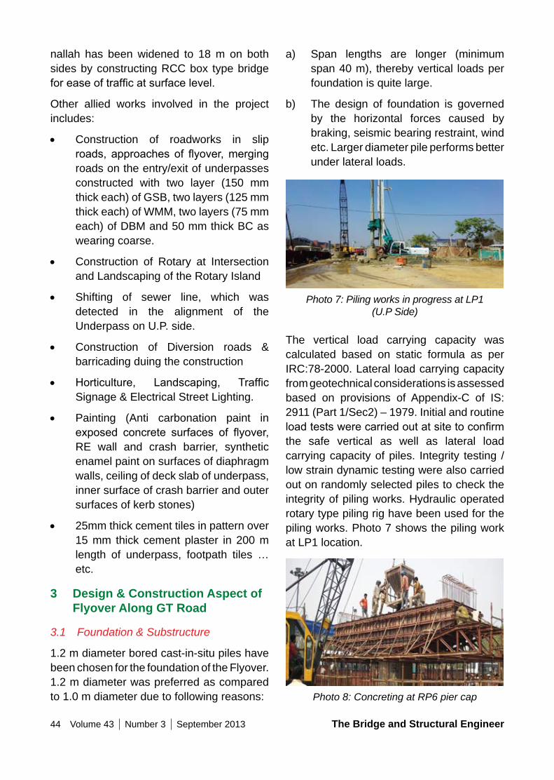
44 Volume 43 Number 3 September 2013 The Bridge and Structural Engineer
a) Span lengths are longer (minimum span 40 m), thereby vertical loads per foundation is quite large.
b) The design of foundation is governed by the horizontal forces caused by braking, seismic bearing restraint, wind etc. Larger diameter pile performs better under lateral loads.
Photo 7: Piling works in progress at LP1 (U.P Side)
The vertical load carrying capacity was calculated based on static formula as per IRC:78-2000. Lateral load carrying capacity from geotechnical considerations is assessed based on provisions of Appendix-C of IS: 2911 (Part 1/Sec2) – 1979. Initial and routine loadtestswerecarriedoutatsitetoconfirmthe safe vertical as well as lateral load carrying capacity of piles. Integrity testing / low strain dynamic testing were also carried out on randomly selected piles to check the integrity of piling works. Hydraulic operated rotary type piling rig have been used for the piling works. Photo 7 shows the piling work at LP1 location.
Photo 8: Concreting at RP6 pier cap
nallah has been widened to 18 m on both sides by constructing RCC box type bridge foreaseoftrafficatsurfacelevel.
Other allied works involved in the project includes:
• Construction of roadworks in slip roads, approachesof flyover,mergingroads on the entry/exit of underpasses constructed with two layer (150 mm thick each) of GSB, two layers (125 mm thick each) of WMM, two layers (75 mm each) of DBM and 50 mm thick BC as wearing coarse.
• Construction of Rotary at Intersection and Landscaping of the Rotary Island
• Shifting of sewer line, which was detected in the alignment of the Underpass on U.P. side.
• Construction of Diversion roads & barricading duing the construction
• Horticulture, Landscaping, TrafficSignage & Electrical Street Lighting.
• Painting (Anti carbonation paint in exposed concrete surfaces of flyover,RE wall and crash barrier, synthetic enamel paint on surfaces of diaphragm walls, ceiling of deck slab of underpass, inner surface of crash barrier and outer surfaces of kerb stones)
• 25mm thick cement tiles in pattern over 15 mm thick cement plaster in 200 m length of underpass, footpath tiles …etc.
3 Design & Construction Aspect of Flyover Along GT Road
3.1 Foundation & Substructure
1.2 m diameter bored cast-in-situ piles have been chosen for the foundation of the Flyover. 1.2 m diameter was preferred as compared to 1.0 m diameter due to following reasons:
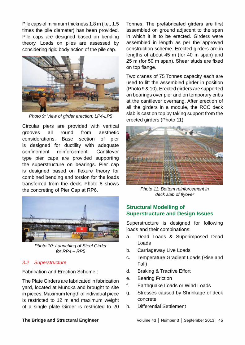
The Bridge and Structural Engineer Volume 43 Number 3 September 2013 45
Tonnes. The prefabricated girders are firstassembled on ground adjacent to the span in which it is to be erected. Girders were assembled in length as per the approved construction scheme. Erected girders are in lengths of about 45 m (for 40 m span) and 25m(for50mspan).Shearstudsarefixedontopflange.
Two cranes of 75 Tonnes capacity each are used to lift the assembled girder in position (Photo 9 & 10). Erected girders are supported on bearings over pier and on temporary cribs at the cantilever overhang. After erection of all the girders in a module, the RCC deck slab is cast on top by taking support from the erected girders (Photo 11).
Photo 11: Bottom reinforcement in deck slab of flyover
Structural Modelling of Superstructure and Design IssuesSuperstructure is designed for following loads and their combinations:a. Dead Loads & Superimposed Dead
Loadsb. Carriageway Live Loadsc. Temperature Gradient Loads (Rise and
Fall)d. Braking & Tractive Efforte. Bearing Frictionf. Earthquake Loads or Wind Loadsg. Stresses caused by Shrinkage of deck
concreteh. Differential Settlement
Pile caps of minimum thickness 1.8 m (i.e., 1.5 times the pile diameter) has been provided. Pile caps are designed based on bending theory. Loads on piles are assessed by considering rigid body action of the pile cap.
Photo 9: View of girder erection: LP4-LP5
Circular piers are provided with vertical grooves all round from aesthetic considerations. Base section of pier is designed for ductility with adequate confinement reinforcement. Cantilevertype pier caps are provided supporting the superstructure on bearings. Pier cap is designed based on flexure theory forcombined bending and torsion for the loads transferred from the deck. Photo 8 shows the concreting of Pier Cap at RP6.
Photo 10: Launching of Steel Girder for RP4 – RP5
3.2 Superstructure
Fabrication and Erection Scheme :
The Plate Girders are fabricated in fabrication yard, located at Mundka and brought to site in pieces. Maximum length of individual piece is restricted to 12 m and maximum weight of a single plate Girder is restricted to 20
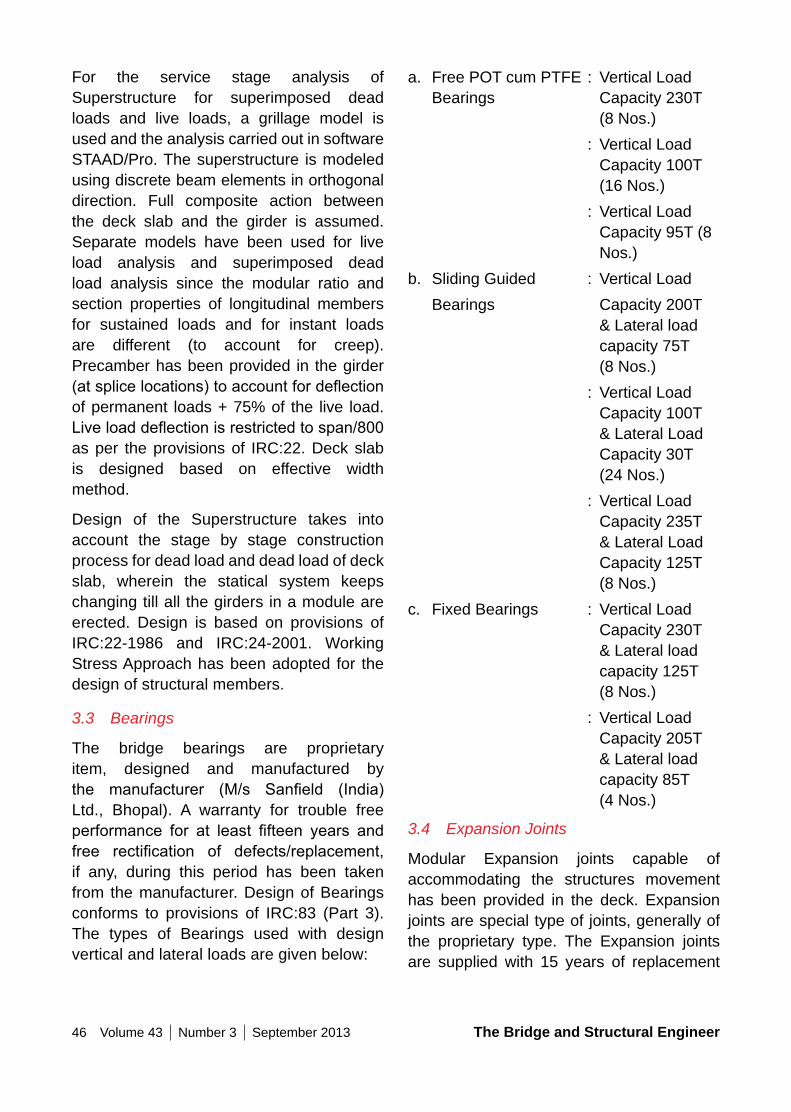
46 Volume 43 Number 3 September 2013 The Bridge and Structural Engineer
For the service stage analysis of Superstructure for superimposed dead loads and live loads, a grillage model is used and the analysis carried out in software STAAD/Pro. The superstructure is modeled using discrete beam elements in orthogonal direction. Full composite action between the deck slab and the girder is assumed. Separate models have been used for live load analysis and superimposed dead load analysis since the modular ratio and section properties of longitudinal members for sustained loads and for instant loads are different (to account for creep). Precamber has been provided in the girder (atsplicelocations)toaccountfordeflectionof permanent loads + 75% of the live load. Liveloaddeflectionisrestrictedtospan/800as per the provisions of IRC:22. Deck slab is designed based on effective width method.
Design of the Superstructure takes into account the stage by stage construction process for dead load and dead load of deck slab, wherein the statical system keeps changing till all the girders in a module are erected. Design is based on provisions of IRC:22-1986 and IRC:24-2001. Working Stress Approach has been adopted for the design of structural members.
3.3 Bearings
The bridge bearings are proprietary item, designed and manufactured by the manufacturer (M/s Sanfield (India)Ltd., Bhopal). A warranty for trouble free performance for at least fifteen years andfree rectification of defects/replacement,if any, during this period has been taken from the manufacturer. Design of Bearings conforms to provisions of IRC:83 (Part 3). The types of Bearings used with design vertical and lateral loads are given below:
a. Free POT cum PTFE : Vertical Load Bearings Capacity 230T
(8 Nos.) : Vertical Load
Capacity 100T (16 Nos.)
: Vertical Load Capacity 95T (8 Nos.)
b. Sliding Guided : Vertical Load Bearings Capacity 200T
& Lateral load capacity 75T (8 Nos.)
: Vertical Load Capacity 100T & Lateral Load Capacity 30T (24 Nos.)
: Vertical Load Capacity 235T & Lateral Load Capacity 125T (8 Nos.)
c. Fixed Bearings : Vertical Load Capacity 230T & Lateral load capacity 125T (8 Nos.)
: Vertical Load Capacity 205T & Lateral load capacity 85T (4 Nos.)
3.4 Expansion Joints
Modular Expansion joints capable of accommodating the structures movement has been provided in the deck. Expansion joints are special type of joints, generally of the proprietary type. The Expansion joints are supplied with 15 years of replacement
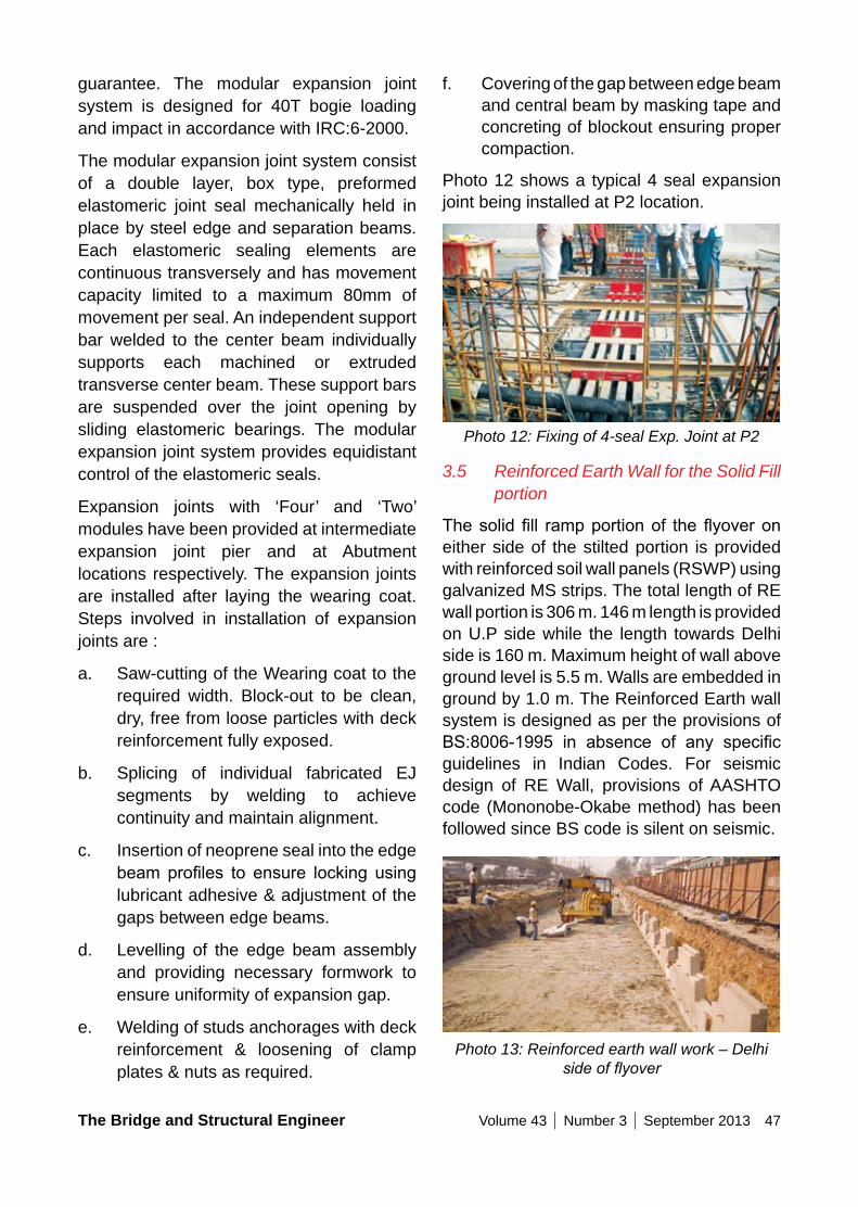
The Bridge and Structural Engineer Volume 43 Number 3 September 2013 47
f. Covering of the gap between edge beam and central beam by masking tape and concreting of blockout ensuring proper compaction.
Photo 12 shows a typical 4 seal expansion joint being installed at P2 location.
Photo 12: Fixing of 4-seal Exp. Joint at P2
3.5 Reinforced Earth Wall for the Solid Fill portion
Thesolidfill rampportionof theflyoveroneither side of the stilted portion is provided with reinforced soil wall panels (RSWP) using galvanized MS strips. The total length of RE wall portion is 306 m. 146 m length is provided on U.P side while the length towards Delhi side is 160 m. Maximum height of wall above ground level is 5.5 m. Walls are embedded in ground by 1.0 m. The Reinforced Earth wall system is designed as per the provisions of BS:8006-1995 in absence of any specificguidelines in Indian Codes. For seismic design of RE Wall, provisions of AASHTO code (Mononobe-Okabe method) has been followed since BS code is silent on seismic.
Photo 13: Reinforced earth wall work – Delhi side of flyover
guarantee. The modular expansion joint system is designed for 40T bogie loading and impact in accordance with IRC:6-2000.
The modular expansion joint system consist of a double layer, box type, preformed elastomeric joint seal mechanically held in place by steel edge and separation beams. Each elastomeric sealing elements are continuous transversely and has movement capacity limited to a maximum 80mm of movement per seal. An independent support bar welded to the center beam individually supports each machined or extruded transverse center beam. These support bars are suspended over the joint opening by sliding elastomeric bearings. The modular expansion joint system provides equidistant control of the elastomeric seals.
Expansion joints with ‘Four’ and ‘Two’ modules have been provided at intermediate expansion joint pier and at Abutment locations respectively. The expansion joints are installed after laying the wearing coat. Steps involved in installation of expansion joints are :
a. Saw-cutting of the Wearing coat to the required width. Block-out to be clean, dry, free from loose particles with deck reinforcement fully exposed.
b. Splicing of individual fabricated EJ segments by welding to achieve continuity and maintain alignment.
c. Insertion of neoprene seal into the edge beam profiles to ensure locking usinglubricant adhesive & adjustment of the gaps between edge beams.
d. Levelling of the edge beam assembly and providing necessary formwork to ensure uniformity of expansion gap.
e. Welding of studs anchorages with deck reinforcement & loosening of clamp plates & nuts as required.
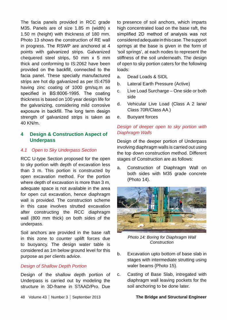
48 Volume 43 Number 3 September 2013 The Bridge and Structural Engineer
to presence of soil anchors, which imparts high concentrated load on the base raft, the simplified 2D method of analysis was notconsidered adequate in this case. The support springs at the base is given in the form of ‘soil springs’, at each nodes to represent the stiffness of the soil underneath. The design of open to sky portion caters for the following loads:a. Dead Loads & SIDLb. Lateral Earth Pressure (Active)c. Live Load Surcharge – One side or both
sided. Vehicular Live Load (Class A 2 lane/
Class 70R/Class AA )e. Buoyant forces
Design of deeper open to sky portion with Diaphragm Walls
Design of the deeper portion of Underpass involving diaphragm walls is carried out using the top down construction method. Different stages of Construction are as follows:
a. Construction of Diaphragm Wall on both sides with M35 grade concrete (Photo 14).
Photo 14: Boring for Diaphragm Wall Construction
b. Excavation upto bottom of base slab in stages with intermediate strutting using waler beams (Photo 15).
c. Casting of Base Slab, intregated with diaphragm wall leaving pockets for the soil anchoring to be done later.
The facia panels provided in RCC grade M35. Panels are of size 1.85 m (width) x 1.50 m (height) with thickness of 180 mm. Photo 13 shows the construction of RE wall in progress. The RSWP are anchored at 4 points with galvanized strips. Galvanized chequered steel strips, 50 mm x 5 mm thick and conforming to IS:2062 have been provided on the backfill, connected to thefacia panel. These specially manufactured strips are hot dip galvanized as per IS:4759 having zinc coating of 1000 gm/sq.m as specified in BS:8006-1995. The coatingthickness is based on 100 year design life for the galvanizing, considering mild corrosive exposure in backfill. The long term designstrength of galvanized strips is taken as 40 KN/m.
4 Design & Construction Aspect of Underpass
4.1 Open to Sky Underpass Section
RCC U-type Section proposed for the open to sky portion with depth of excavation less than 3 m. This portion is constructed by open excavation method. For the portion where depth of excavation is more than 3 m, adequate space is not available in the area for open cut excavation, hence diaphragm wall is provided. The construction scheme in this case involves strutted excavation after constructing the RCC diaphragm wall (800 mm thick) on both sides of the underpass.
Soil anchors are provided in the base raft in this zone to counter uplift forces due to buoyancy. The design water table is considered as 1m below ground level for this purpose as per clients advice.
Design of Shallow Depth Portion
Design of the shallow depth portion of Underpass is carried out by modeling the structure in 3D-frame in STAAD/Pro. Due
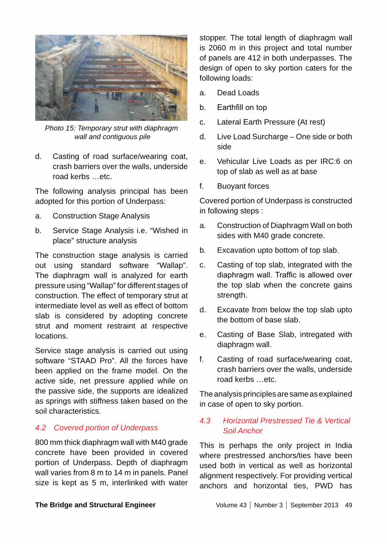
The Bridge and Structural Engineer Volume 43 Number 3 September 2013 49
Photo 15: Temporary strut with diaphragm wall and contiguous pile
d. Casting of road surface/wearing coat, crash barriers over the walls, underside road kerbs …etc.
The following analysis principal has been adopted for this portion of Underpass:
a. Construction Stage Analysis
b. Service Stage Analysis i.e. “Wished in place” structure analysis
The construction stage analysis is carried out using standard software “Wallap”. The diaphragm wall is analyzed for earth pressure using “Wallap” for different stages of construction. The effect of temporary strut at intermediate level as well as effect of bottom slab is considered by adopting concrete strut and moment restraint at respective locations.
Service stage analysis is carried out using software “STAAD Pro”. All the forces have been applied on the frame model. On the active side, net pressure applied while on the passive side, the supports are idealized as springs with stiffness taken based on the soil characteristics.
4.2 Covered portion of Underpass
800 mm thick diaphragm wall with M40 grade concrete have been provided in covered portion of Underpass. Depth of diaphragm wall varies from 8 m to 14 m in panels. Panel size is kept as 5 m, interlinked with water
stopper. The total length of diaphragm wall is 2060 m in this project and total number of panels are 412 in both underpasses. The design of open to sky portion caters for the following loads:
a. Dead Loads
b. Earthfillontop
c. Lateral Earth Pressure (At rest)
d. Live Load Surcharge – One side or both side
e. Vehicular Live Loads as per IRC:6 on top of slab as well as at base
f. Buoyant forces
Covered portion of Underpass is constructed in following steps :
a. Construction of Diaphragm Wall on both sides with M40 grade concrete.
b. Excavation upto bottom of top slab.
c. Casting of top slab, integrated with the diaphragmwall.Trafficisallowedoverthe top slab when the concrete gains strength.
d. Excavate from below the top slab upto the bottom of base slab.
e. Casting of Base Slab, intregated with diaphragm wall.
f. Casting of road surface/wearing coat, crash barriers over the walls, underside road kerbs …etc.
The analysis principles are same as explained in case of open to sky portion.
4.3 Horizontal Prestressed Tie & Vertical Soil Anchor
This is perhaps the only project in India where prestressed anchors/ties have been used both in vertical as well as horizontal alignment respectively. For providing vertical anchors and horizontal ties, PWD has
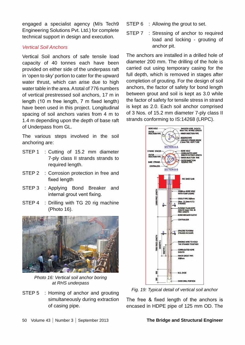
50 Volume 43 Number 3 September 2013 The Bridge and Structural Engineer
STEP 6 : Allowing the grout to set.
STEP 7 : Stressing of anchor to required load and locking - grouting of anchor pit.
The anchors are installed in a drilled hole of diameter 200 mm. The drilling of the hole is carried out using temporary casing for the full depth, which is removed in stages after completion of grouting. For the design of soil anchors, the factor of safety for bond length between grout and soil is kept as 3.0 while the factor of safety for tensile stress in strand is kept as 2.0. Each soil anchor comprised of 3 Nos. of 15.2 mm diameter 7-ply class II strands conforming to IS:14268 (LRPC).
Fig. 19: Typical detail of vertical soil anchor
The free & fixed length of the anchors isencased in HDPE pipe of 125 mm OD. The
engaged a specialist agency (M/s Tech9 Engineering Solutions Pvt. Ltd.) for complete technical support in design and execution.
Vertical Soil Anchors
Vertical Soil anchors of safe tensile load capacity of 40 tonnes each have been provided on either side of the underpass raft in ‘open to sky’ portion to cater for the upward water thrust, which can arise due to high water table in the area. A total of 776 numbers of vertical prestressed soil anchors, 17 m in length (10m free length,7mfixed length)have been used in this project. Longitudinal spacing of soil anchors varies from 4 m to 1.4 m depending upon the depth of base raft of Underpass from GL.
The various steps involved in the soil anchoring are:
STEP 1 : Cutting of 15.2 mm diameter 7-ply class II strands strands to required length.
STEP 2 : Corrosion protection in free and fixedlength
STEP 3 : Applying Bond Breaker and internalgroutventfixing.
STEP 4 : Drilling with TG 20 rig machine (Photo 16).
Photo 16: Vertical soil anchor boring at RHS underpass
STEP 5 : Homing of anchor and grouting simultaneously during extraction of casing pipe.
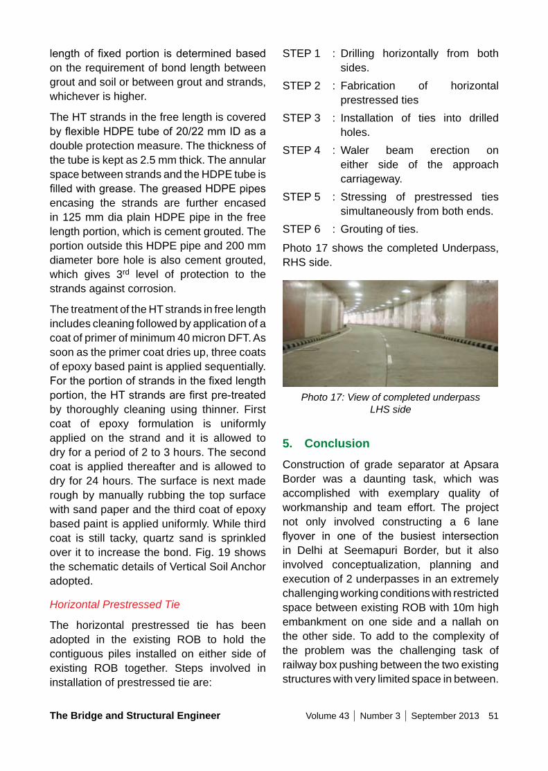
The Bridge and Structural Engineer Volume 43 Number 3 September 2013 51
STEP 1 : Drilling horizontally from both sides.
STEP 2 : Fabrication of horizontal prestressed ties
STEP 3 : Installation of ties into drilled holes.
STEP 4 : Waler beam erection on either side of the approach carriageway.
STEP 5 : Stressing of prestressed ties simultaneously from both ends.
STEP 6 : Grouting of ties.
Photo 17 shows the completed Underpass, RHS side.
Photo 17: View of completed underpass LHS side
5. ConclusionConstruction of grade separator at Apsara Border was a daunting task, which was accomplished with exemplary quality of workmanship and team effort. The project not only involved constructing a 6 lane flyover in one of the busiest intersectionin Delhi at Seemapuri Border, but it also involved conceptualization, planning and execution of 2 underpasses in an extremely challenging working conditions with restricted space between existing ROB with 10m high embankment on one side and a nallah on the other side. To add to the complexity of the problem was the challenging task of railway box pushing between the two existing structures with very limited space in between.
lengthoffixedportion isdeterminedbasedon the requirement of bond length between grout and soil or between grout and strands, whichever is higher.
The HT strands in the free length is covered byflexibleHDPEtubeof20/22mmIDasadouble protection measure. The thickness of the tube is kept as 2.5 mm thick. The annular space between strands and the HDPE tube is filledwithgrease.ThegreasedHDPEpipesencasing the strands are further encased in 125 mm dia plain HDPE pipe in the free length portion, which is cement grouted. The portion outside this HDPE pipe and 200 mm diameter bore hole is also cement grouted, which gives 3rd level of protection to the strands against corrosion.
The treatment of the HT strands in free length includes cleaning followed by application of a coat of primer of minimum 40 micron DFT. As soon as the primer coat dries up, three coats of epoxy based paint is applied sequentially. Fortheportionofstrandsinthefixedlengthportion,theHTstrandsarefirstpre-treatedby thoroughly cleaning using thinner. First coat of epoxy formulation is uniformly applied on the strand and it is allowed to dry for a period of 2 to 3 hours. The second coat is applied thereafter and is allowed to dry for 24 hours. The surface is next made rough by manually rubbing the top surface with sand paper and the third coat of epoxy based paint is applied uniformly. While third coat is still tacky, quartz sand is sprinkled over it to increase the bond. Fig. 19 shows the schematic details of Vertical Soil Anchor adopted.
Horizontal Prestressed Tie
The horizontal prestressed tie has been adopted in the existing ROB to hold the contiguous piles installed on either side of existing ROB together. Steps involved in installation of prestressed tie are:
52 Volume 43 Number 3 September 2013 The Bridge and Structural Engineer
Narain (EE,PWD) are noteworthy. Author is also grateful to the unsung heroes from the Consultant, Proof Consultant, Contractors as well as from PWD, whose deep involvement and untiring efforts have helped to complete such a complex project in reasonable time.
Credits:
• Client : PUBLIC WORKS DEPARTMENT, NCT DELHI
• Design Consultant : M/s CRAFTS CONSULTANTS (I) PVT. LTD.
• Proof Consultant : M/s B&S ENGINEERING CONSULTANTS PVT. LTD.
• Contractor : M/s AFCONS INFRASTRUCTURE LIMITED, MUMBAI
• Quality Assurance : DELHI TECHNOLOGICAL UNIVERSITY (Formerly DELHI COLLEGE OF ENGINEERING)
The challenge posed brought out number of innovative solutions, both in design as well as in execution, which had never been tried before. Credit for successful completion of this project goes to the excellent team work and understanding between the Client (PWD), Proof Consultant, Contractor & the Design Consultant.
Quantities of Major items in this project:
1. Cement : 35,034 MT
2. Reinforcement : 9277 MT
3. Structural Steel, : 1811 MT Superstructure
4. Structural Steel, : 430 MT Waler Beam
5. Concrete : 92,500 cu.m
6. Bitumen : 857 MT
AcknowledgementsThe author wish to place on records his appreciation for the co-operation received from the authorities of Delhi PWD (NCTD) during the entire duration of this project and also in writing this paper. The co-operation extended by Shri U C Mishra (Project Manager, PWD), Shri Kailash
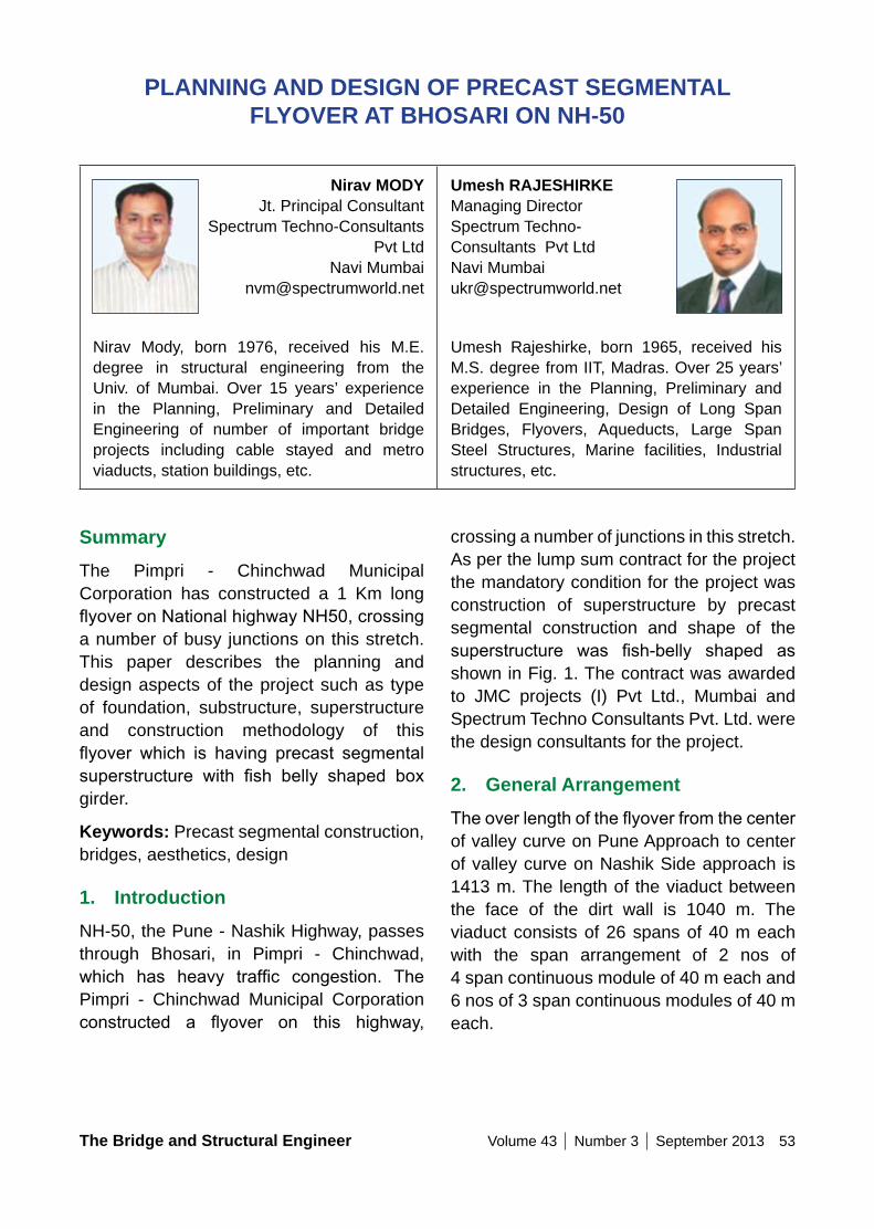
The Bridge and Structural Engineer Volume 43 Number 3 September 2013 53
SummaryThe Pimpri - Chinchwad Municipal Corporation has constructed a 1 Km long flyoveronNationalhighwayNH50,crossinga number of busy junctions on this stretch. This paper describes the planning and design aspects of the project such as type of foundation, substructure, superstructure and construction methodology of this flyover which is having precast segmentalsuperstructure with fish belly shaped boxgirder.
Keywords: Precast segmental construction, bridges, aesthetics, design
1. IntroductionNH-50, the Pune - Nashik Highway, passes through Bhosari, in Pimpri - Chinchwad, which has heavy traffic congestion. ThePimpri - Chinchwad Municipal Corporation constructed a flyover on this highway,
PLAnnInG AnD DESIGn oF PRECAST SEGMEnTAL FLyoVER AT BHoSARI on nH-50
nirav MoDy Jt. Principal Consultant
Spectrum Techno-Consultants Pvt Ltd
Navi Mumbai [email protected]
Nirav Mody, born 1976, received his M.E. degree in structural engineering from the Univ. of Mumbai. Over 15 years’ experience in the Planning, Preliminary and Detailed Engineering of number of important bridge projects including cable stayed and metro viaducts, station buildings, etc.
Umesh RAJESHIRKE Managing Director Spectrum Techno- Consultants Pvt Ltd Navi Mumbai [email protected]
Umesh Rajeshirke, born 1965, received his M.S. degree from IIT, Madras. Over 25 years’ experience in the Planning, Preliminary and Detailed Engineering, Design of Long Span Bridges, Flyovers, Aqueducts, Large Span Steel Structures, Marine facilities, Industrial structures, etc.
crossing a number of junctions in this stretch. As per the lump sum contract for the project the mandatory condition for the project was construction of superstructure by precast segmental construction and shape of the superstructure was fish-belly shaped asshown in Fig. 1. The contract was awarded to JMC projects (I) Pvt Ltd., Mumbai and Spectrum Techno Consultants Pvt. Ltd. were the design consultants for the project.
2. General ArrangementTheoverlengthoftheflyoverfromthecenterof valley curve on Pune Approach to center of valley curve on Nashik Side approach is 1413 m. The length of the viaduct between the face of the dirt wall is 1040 m. The viaduct consists of 26 spans of 40 m each with the span arrangement of 2 nos of 4 span continuous module of 40 m each and 6 nos of 3 span continuous modules of 40 m each.
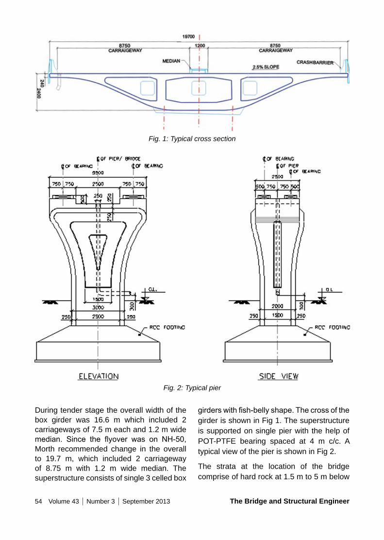
54 Volume 43 Number 3 September 2013 The Bridge and Structural Engineer
Fig. 1: Typical cross section
Fig. 2: Typical pier
During tender stage the overall width of the box girder was 16.6 m which included 2 carriageways of 7.5 m each and 1.2 m wide median. Since the flyover was on NH-50,Morth recommended change in the overall to 19.7 m, which included 2 carriageway of 8.75 m with 1.2 m wide median. The superstructure consists of single 3 celled box
girderswithfish-bellyshape.Thecrossofthegirder is shown in Fig 1. The superstructure is supported on single pier with the help of POT-PTFE bearing spaced at 4 m c/c. A typical view of the pier is shown in Fig 2.
The strata at the location of the bridge comprise of hard rock at 1.5 m to 5 m below
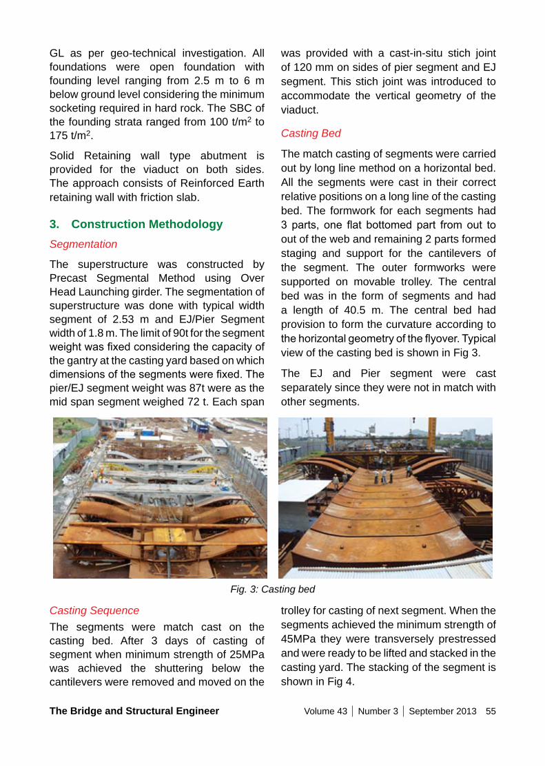
The Bridge and Structural Engineer Volume 43 Number 3 September 2013 55
was provided with a cast-in-situ stich joint of 120 mm on sides of pier segment and EJ segment. This stich joint was introduced to accommodate the vertical geometry of the viaduct.
Casting Bed
The match casting of segments were carried out by long line method on a horizontal bed. All the segments were cast in their correct relative positions on a long line of the casting bed. The formwork for each segments had 3parts, one flat bottomedpart fromout toout of the web and remaining 2 parts formed staging and support for the cantilevers of the segment. The outer formworks were supported on movable trolley. The central bed was in the form of segments and had a length of 40.5 m. The central bed had provision to form the curvature according to thehorizontalgeometryoftheflyover.Typicalview of the casting bed is shown in Fig 3.
The EJ and Pier segment were cast separately since they were not in match with other segments.
GL as per geo-technical investigation. All foundations were open foundation with founding level ranging from 2.5 m to 6 m below ground level considering the minimum socketing required in hard rock. The SBC of the founding strata ranged from 100 t/m2 to 175 t/m2.
Solid Retaining wall type abutment is provided for the viaduct on both sides. The approach consists of Reinforced Earth retaining wall with friction slab.
3. Construction MethodologySegmentation
The superstructure was constructed by Precast Segmental Method using Over Head Launching girder. The segmentation of superstructure was done with typical width segment of 2.53 m and EJ/Pier Segment width of 1.8 m. The limit of 90t for the segment weightwasfixedconsideringthecapacityofthe gantry at the casting yard based on which dimensionsofthesegmentswerefixed.Thepier/EJ segment weight was 87t were as the mid span segment weighed 72 t. Each span
Fig. 3: Casting bed
Casting SequenceThe segments were match cast on the casting bed. After 3 days of casting of segment when minimum strength of 25MPa was achieved the shuttering below the cantilevers were removed and moved on the
trolley for casting of next segment. When the segments achieved the minimum strength of 45MPa they were transversely prestressed and were ready to be lifted and stacked in the casting yard. The stacking of the segment is shown in Fig 4.
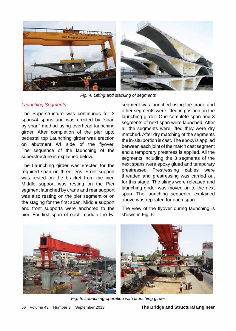
56 Volume 43 Number 3 September 2013 The Bridge and Structural Engineer
Launching Segments
The Superstructure was continuous for 3 spans/4 spans and was erected by “span by span” method using overhead launching girder. After completion of the pier upto pedestal top Launching girder was erection on abutment A1 side of the flyover.The sequence of the launching of the superstructure is explained below.
The Launching girder was erected for the required span on three legs. Front support was rested on the bracket from the pier, Middle support was resting on the Pier segment launched by crane and rear support was also resting on the pier segment or on thestagingforthefirstspan.Middlesupportand front supports were anchored to the pier. For first span of eachmodule the EJ
segment was launched using the crane and other segments were lifted in position on the launching girder. One complete span and 3 segments of next span were launched. After all the segments were lifted they were dry matched. After dry matching of the segments the in-situ portion is cast. The epoxy is applied between each joint of the match cast segment and a temporary prestress is applied. All the segments including the 3 segments of the next spans were epoxy glued and temporary prestressed Prestressing cables were threaded and prestressing was carried out for this stage. The slings were released and launching girder was moved on to the next span. The launching sequence explained above was repeated for each span.
Theviewof the flyoverduring launching isshown in Fig. 5
Fig. 4: Lifting and stacking of segments
Fig. 5: Launching operation with launching girder
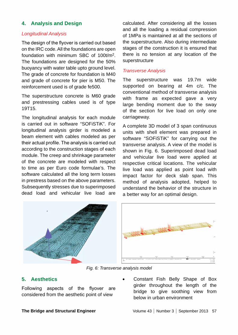
The Bridge and Structural Engineer Volume 43 Number 3 September 2013 57
calculated. After considering all the losses and all the loading a residual compression of 1MPa is maintained at all the sections of the superstructure. Also during intermediate stages of the construction it is ensured that there is no tension at any location of the superstructure
Transverse Analysis
The superstructure was 19.7m wide supported on bearing at 4m c/c. The conventional method of transverse analysis with frame as expected gave a very large bending moment due to the sway of the section for live load on only one carriageway.
A complete 3D model of 3 span continuous units with shell element was prepared in software “SOFiSTiK” for carrying out the transverse analysis. A view of the model is shown in Fig. 6. Superimposed dead load and vehicular live load were applied at respective critical locations. The vehicular live load was applied as point load with impact factor for deck slab span. This method of analysis adopted, helped to understand the behavior of the structure in a better way for an optimal design.
4. Analysis and Design
Longitudinal Analysis
Thedesignoftheflyoveriscarriedoutbasedon the IRC code. All the foundations are open foundation with minimum SBC of 100t/m2. The foundations are designed for the 50% buoyancy with water table upto ground level. The grade of concrete for foundation is M40 and grade of concrete for pier is M50. The reinforcement used is of grade fe500.
The superstructure concrete is M60 grade and prestressing cables used is of type 19T15.
The longitudinal analysis for each module is carried out in software “SOFiSTiK”. For longitudinal analysis girder is modeled a beam element with cables modeled as per theiractualprofile.Theanalysisiscarriedoutaccording to the construction stages of each module. The creep and shrinkage parameter of the concrete are modeled with respect to time as per Euro code formulae’s. The software calculated all the long term losses in prestress based on the above parameters. Subsequently stresses due to superimposed dead load and vehicular live load are
Fig. 6: Transverse analysis model
5. AestheticsFollowing aspects of the flyover areconsidered from the aesthetic point of view
• Constant Fish Belly Shape of Box girder throughout the length of the bridge to give soothing view from below in urban environment
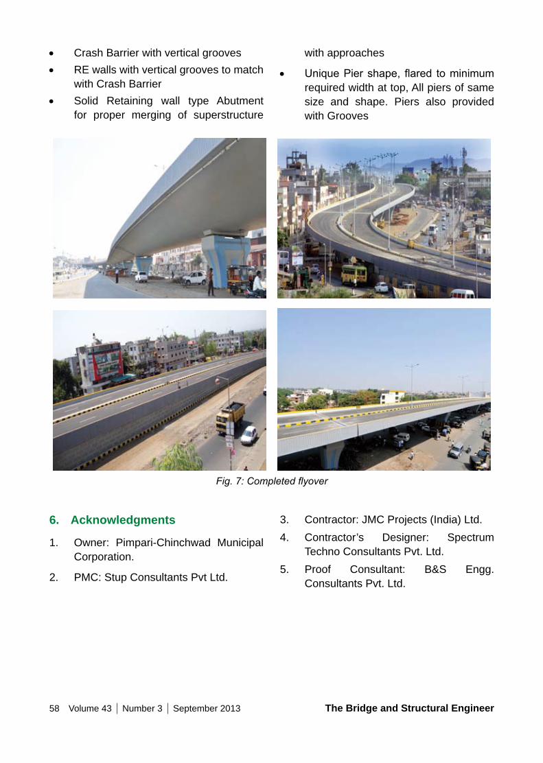
58 Volume 43 Number 3 September 2013 The Bridge and Structural Engineer
with approaches
• UniquePiershape,flared tominimumrequired width at top, All piers of same size and shape. Piers also provided with Grooves
• Crash Barrier with vertical grooves• RE walls with vertical grooves to match
with Crash Barrier• Solid Retaining wall type Abutment
for proper merging of superstructure
6. Acknowledgments
1. Owner: Pimpari-Chinchwad Municipal Corporation.
2. PMC: Stup Consultants Pvt Ltd.
3. Contractor: JMC Projects (India) Ltd.4. Contractor’s Designer: Spectrum
Techno Consultants Pvt. Ltd.5. Proof Consultant: B&S Engg.
Consultants Pvt. Ltd.
Fig. 7: Completed flyover
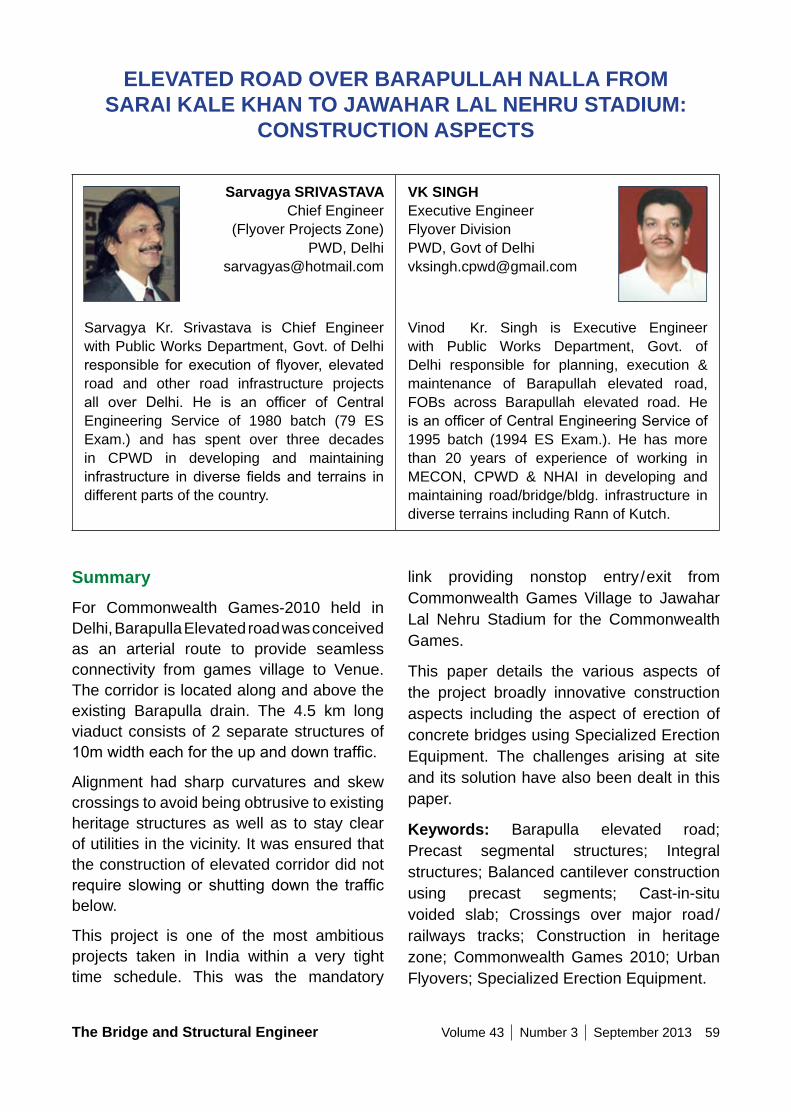
The Bridge and Structural Engineer Volume 43 Number 3 September 2013 59
SummaryFor Commonwealth Games-2010 held in Delhi, Barapulla Elevated road was conceived as an arterial route to provide seamless connectivity from games village to Venue. The corridor is located along and above the existing Barapulla drain. The 4.5 km long viaduct consists of 2 separate structures of 10mwidtheachfortheupanddowntraffic.
Alignment had sharp curvatures and skew crossings to avoid being obtrusive to existing heritage structures as well as to stay clear of utilities in the vicinity. It was ensured that the construction of elevated corridor did not require slowingor shuttingdown the trafficbelow.
This project is one of the most ambitious projects taken in India within a very tight time schedule. This was the mandatory
ELEVATED RoAD oVER BARAPULLAH nALLA FRoM SARAI KALE KHAn To JAWAHAR LAL nEHRU STADIUM:
ConSTRUCTIon ASPECTS
Sarvagya SRIVASTAVAChief Engineer
(Flyover Projects Zone)PWD, Delhi
Sarvagya Kr. Srivastava is Chief Engineer with Public Works Department, Govt. of Delhi responsible for execution of flyover, elevatedroad and other road infrastructure projects all over Delhi. He is an officer of CentralEngineering Service of 1980 batch (79 ES Exam.) and has spent over three decades in CPWD in developing and maintaining infrastructure in diverse fields and terrains indifferent parts of the country.
VK SInGHExecutive EngineerFlyover DivisionPWD, Govt of [email protected]
Vinod Kr. Singh is Executive Engineer with Public Works Department, Govt. of Delhi responsible for planning, execution & maintenance of Barapullah elevated road, FOBs across Barapullah elevated road. He isanofficerofCentralEngineeringServiceof1995 batch (1994 ES Exam.). He has more than 20 years of experience of working in MECON, CPWD & NHAI in developing and maintaining road/bridge/bldg. infrastructure in diverse terrains including Rann of Kutch.
link providing nonstop entry/exit from Commonwealth Games Village to Jawahar Lal Nehru Stadium for the Commonwealth Games.
This paper details the various aspects of the project broadly innovative construction aspects including the aspect of erection of concrete bridges using Specialized Erection Equipment. The challenges arising at site and its solution have also been dealt in this paper.
Keywords: Barapulla elevated road; Precast segmental structures; Integral structures; Balanced cantilever construction using precast segments; Cast-in-situ voided slab; Crossings over major road/railways tracks; Construction in heritage zone; Commonwealth Games 2010; Urban Flyovers; Specialized Erection Equipment.
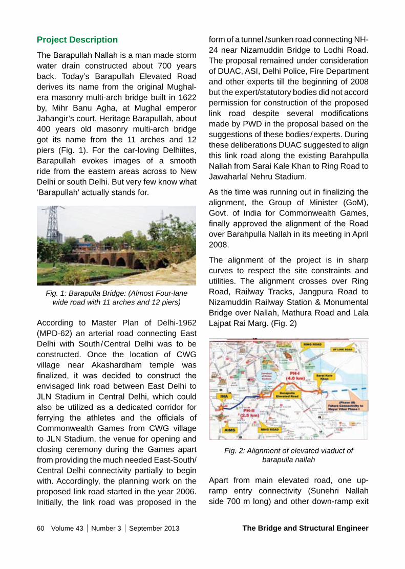
60 Volume 43 Number 3 September 2013 The Bridge and Structural Engineer
Project DescriptionThe Barapullah Nallah is a man made storm water drain constructed about 700 years back. Today’s Barapullah Elevated Road derives its name from the original Mughal-era masonry multi-arch bridge built in 1622 by, Mihr Banu Agha, at Mughal emperor Jahangir’s court. Heritage Barapullah, about 400 years old masonry multi-arch bridge got its name from the 11 arches and 12 piers (Fig. 1). For the car-loving Delhiites, Barapullah evokes images of a smooth ride from the eastern areas across to New Delhi or south Delhi. But very few know what ‘Barapullah’ actually stands for.
Fig. 1: Barapulla Bridge: (Almost Four-lane wide road with 11 arches and 12 piers)
According to Master Plan of Delhi-1962 (MPD-62) an arterial road connecting East Delhi with South/Central Delhi was to be constructed. Once the location of CWG village near Akashardham temple was finalized, it was decided to construct theenvisaged link road between East Delhi to JLN Stadium in Central Delhi, which could also be utilized as a dedicated corridor for ferrying the athletes and the officials ofCommonwealth Games from CWG village to JLN Stadium, the venue for opening and closing ceremony during the Games apart from providing the much needed East-South/Central Delhi connectivity partially to begin with. Accordingly, the planning work on the proposed link road started in the year 2006. Initially, the link road was proposed in the
form of a tunnel /sunken road connecting NH-24 near Nizamuddin Bridge to Lodhi Road. The proposal remained under consideration of DUAC, ASI, Delhi Police, Fire Department and other experts till the beginning of 2008 but the expert/statutory bodies did not accord permission for construction of the proposed link road despite several modificationsmade by PWD in the proposal based on the suggestions of these bodies/experts. During these deliberations DUAC suggested to align this link road along the existing Barahpulla Nallah from Sarai Kale Khan to Ring Road to Jawaharlal Nehru Stadium.
Asthetimewasrunningoutinfinalizingthealignment, the Group of Minister (GoM), Govt. of India for Commonwealth Games, finally approved thealignmentof theRoadover Barahpulla Nallah in its meeting in April 2008.
The alignment of the project is in sharp curves to respect the site constraints and utilities. The alignment crosses over Ring Road, Railway Tracks, Jangpura Road to Nizamuddin Railway Station & Monumental Bridge over Nallah, Mathura Road and Lala Lajpat Rai Marg. (Fig. 2)
Fig. 2: Alignment of elevated viaduct of barapulla nallah
Apart from main elevated road, one up-ramp entry connectivity (Sunehri Nallah side 700 m long) and other down-ramp exit
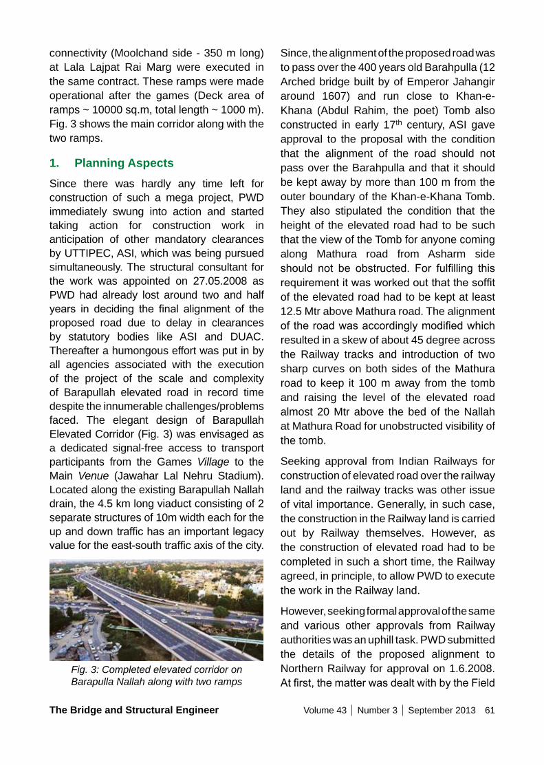
The Bridge and Structural Engineer Volume 43 Number 3 September 2013 61
connectivity (Moolchand side - 350 m long) at Lala Lajpat Rai Marg were executed in the same contract. These ramps were made operational after the games (Deck area of ramps ~ 10000 sq.m, total length ~ 1000 m). Fig. 3 shows the main corridor along with the two ramps.
1. Planning AspectsSince there was hardly any time left for construction of such a mega project, PWD immediately swung into action and started taking action for construction work in anticipation of other mandatory clearances by UTTIPEC, ASI, which was being pursued simultaneously. The structural consultant for the work was appointed on 27.05.2008 as PWD had already lost around two and half years in deciding the final alignment of theproposed road due to delay in clearances by statutory bodies like ASI and DUAC. Thereafter a humongous effort was put in by all agencies associated with the execution of the project of the scale and complexity of Barapullah elevated road in record time despite the innumerable challenges/problems faced. The elegant design of Barapullah Elevated Corridor (Fig. 3) was envisaged as a dedicated signal-free access to transport participants from the Games Village to the Main Venue (Jawahar Lal Nehru Stadium). Located along the existing Barapullah Nallah drain, the 4.5 km long viaduct consisting of 2 separate structures of 10m width each for the upanddowntraffichasanimportantlegacyvaluefortheeast-southtrafficaxisofthecity.
Fig. 3: Completed elevated corridor on Barapulla Nallah along with two ramps
Since, the alignment of the proposed road was to pass over the 400 years old Barahpulla (12 Arched bridge built by of Emperor Jahangir around 1607) and run close to Khan-e-Khana (Abdul Rahim, the poet) Tomb also constructed in early 17th century, ASI gave approval to the proposal with the condition that the alignment of the road should not pass over the Barahpulla and that it should be kept away by more than 100 m from the outer boundary of the Khan-e-Khana Tomb. They also stipulated the condition that the height of the elevated road had to be such that the view of the Tomb for anyone coming along Mathura road from Asharm side should not be obstructed. For fulfilling thisrequirementitwasworkedoutthatthesoffitof the elevated road had to be kept at least 12.5 Mtr above Mathura road. The alignment oftheroadwasaccordinglymodifiedwhichresulted in a skew of about 45 degree across the Railway tracks and introduction of two sharp curves on both sides of the Mathura road to keep it 100 m away from the tomb and raising the level of the elevated road almost 20 Mtr above the bed of the Nallah at Mathura Road for unobstructed visibility of the tomb.
Seeking approval from Indian Railways for construction of elevated road over the railway land and the railway tracks was other issue of vital importance. Generally, in such case, the construction in the Railway land is carried out by Railway themselves. However, as the construction of elevated road had to be completed in such a short time, the Railway agreed, in principle, to allow PWD to execute the work in the Railway land.
However, seeking formal approval of the same and various other approvals from Railway authorities was an uphill task. PWD submitted the details of the proposed alignment to Northern Railway for approval on 1.6.2008. Atfirst,thematterwasdealtwithbytheField
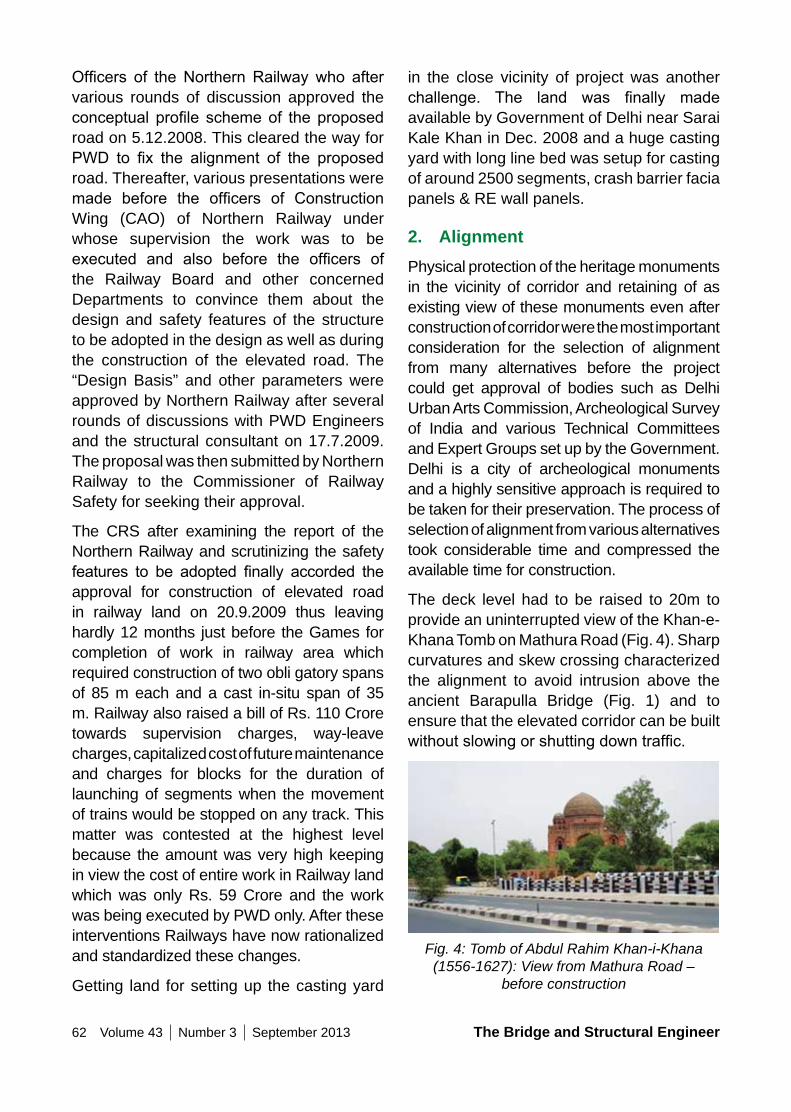
62 Volume 43 Number 3 September 2013 The Bridge and Structural Engineer
Officers of theNorthernRailwaywho aftervarious rounds of discussion approved the conceptual profile schemeof the proposedroad on 5.12.2008. This cleared the way for PWD to fix the alignment of the proposedroad. Thereafter, various presentations were made before the officers of Construction Wing (CAO) of Northern Railway under whose supervision the work was to be executed and also before the officers ofthe Railway Board and other concerned Departments to convince them about the design and safety features of the structure to be adopted in the design as well as during the construction of the elevated road. The “Design Basis” and other parameters were approved by Northern Railway after several rounds of discussions with PWD Engineers and the structural consultant on 17.7.2009. The proposal was then submitted by Northern Railway to the Commissioner of Railway Safety for seeking their approval.
The CRS after examining the report of the Northern Railway and scrutinizing the safety features to be adopted finally accorded theapproval for construction of elevated road in railway land on 20.9.2009 thus leaving hardly 12 months just before the Games for completion of work in railway area which required construction of two obli gatory spans of 85 m each and a cast in-situ span of 35 m. Railway also raised a bill of Rs. 110 Crore towards supervision charges, way-leave charges, capitalized cost of future maintenance and charges for blocks for the duration of launching of segments when the movement of trains would be stopped on any track. This matter was contested at the highest level because the amount was very high keeping in view the cost of entire work in Railway land which was only Rs. 59 Crore and the work was being executed by PWD only. After these interventions Railways have now rationalized and standardized these changes.
Getting land for setting up the casting yard
in the close vicinity of project was another challenge. The land was finally madeavailable by Government of Delhi near Sarai Kale Khan in Dec. 2008 and a huge casting yard with long line bed was setup for casting of around 2500 segments, crash barrier facia panels & RE wall panels.
2. AlignmentPhysical protection of the heritage monuments in the vicinity of corridor and retaining of as existing view of these monuments even after construction of corridor were the most important consideration for the selection of alignment from many alternatives before the project could get approval of bodies such as Delhi Urban Arts Commission, Archeological Survey of India and various Technical Committees and Expert Groups set up by the Government. Delhi is a city of archeological monuments and a highly sensitive approach is required to be taken for their preservation. The process of selection of alignment from various alternatives took considerable time and compressed the available time for construction.
The deck level had to be raised to 20m to provide an uninterrupted view of the Khan-e-Khana Tomb on Mathura Road (Fig. 4). Sharp curvatures and skew crossing characterized the alignment to avoid intrusion above the ancient Barapulla Bridge (Fig. 1) and to ensure that the elevated corridor can be built withoutslowingorshuttingdowntraffic.
Fig. 4: Tomb of Abdul Rahim Khan-i-Khana (1556-1627): View from Mathura Road –
before construction
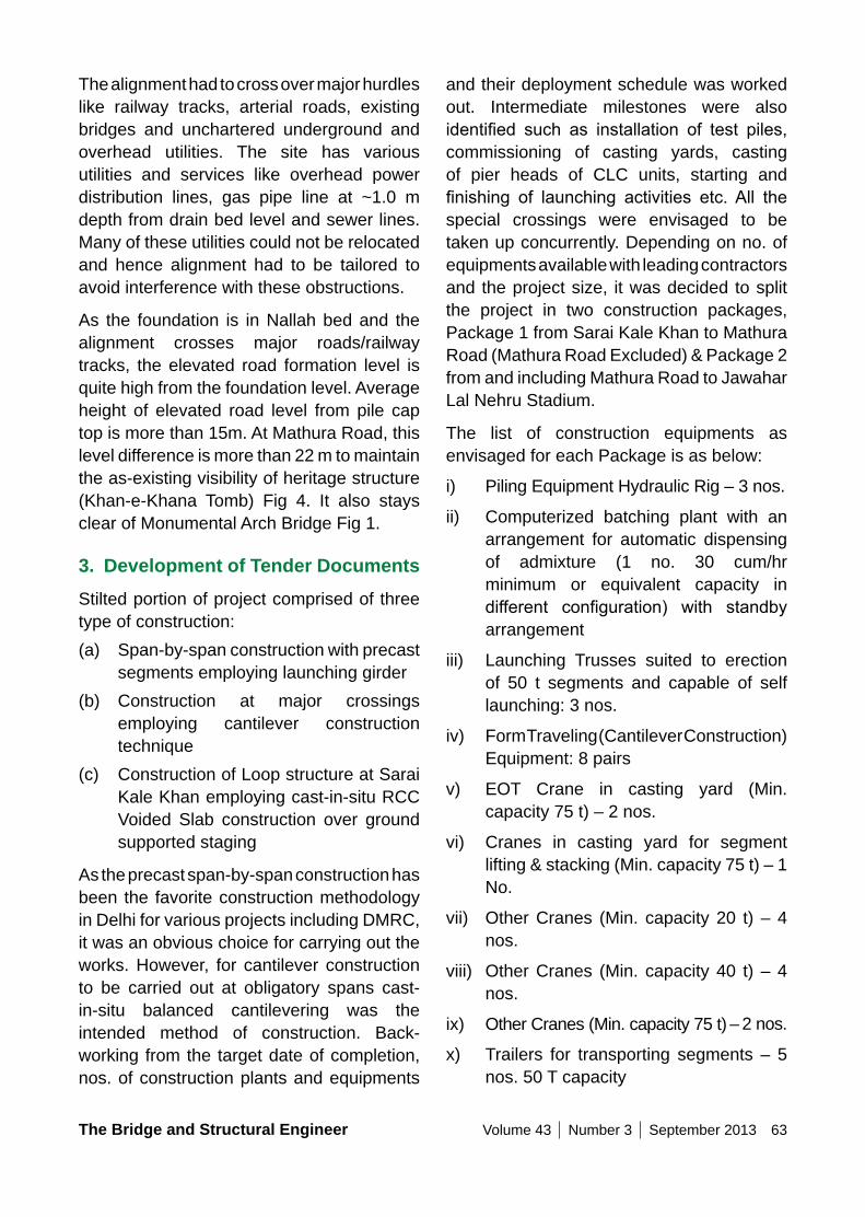
The Bridge and Structural Engineer Volume 43 Number 3 September 2013 63
The alignment had to cross over major hurdles like railway tracks, arterial roads, existing bridges and unchartered underground and overhead utilities. The site has various utilities and services like overhead power distribution lines, gas pipe line at ~1.0 m depth from drain bed level and sewer lines. Many of these utilities could not be relocated and hence alignment had to be tailored to avoid interference with these obstructions.
As the foundation is in Nallah bed and the alignment crosses major roads/railway tracks, the elevated road formation level is quite high from the foundation level. Average height of elevated road level from pile cap top is more than 15m. At Mathura Road, this level difference is more than 22 m to maintain the as-existing visibility of heritage structure (Khan-e-Khana Tomb) Fig 4. It also stays clear of Monumental Arch Bridge Fig 1.
3. Development of Tender DocumentsStilted portion of project comprised of three type of construction:(a) Span-by-span construction with precast
segments employing launching girder(b) Construction at major crossings
employing cantilever construction technique
(c) Construction of Loop structure at Sarai Kale Khan employing cast-in-situ RCC Voided Slab construction over ground supported staging
As the precast span-by-span construction has been the favorite construction methodology in Delhi for various projects including DMRC, it was an obvious choice for carrying out the works. However, for cantilever construction to be carried out at obligatory spans cast-in-situ balanced cantilevering was the intended method of construction. Back-working from the target date of completion, nos. of construction plants and equipments
and their deployment schedule was worked out. Intermediate milestones were also identified such as installation of test piles,commissioning of casting yards, casting of pier heads of CLC units, starting and finishing of launching activities etc.All thespecial crossings were envisaged to be taken up concurrently. Depending on no. of equipments available with leading contractors and the project size, it was decided to split the project in two construction packages, Package 1 from Sarai Kale Khan to Mathura Road (Mathura Road Excluded) & Package 2 from and including Mathura Road to Jawahar Lal Nehru Stadium.
The list of construction equipments as envisaged for each Package is as below:
i) Piling Equipment Hydraulic Rig – 3 nos.
ii) Computerized batching plant with an arrangement for automatic dispensing of admixture (1 no. 30 cum/hr minimum or equivalent capacity in different configuration) with standbyarrangement
iii) Launching Trusses suited to erection of 50 t segments and capable of self launching: 3 nos.
iv) Form Traveling (Cantilever Construction) Equipment: 8 pairs
v) EOT Crane in casting yard (Min. capacity 75 t) – 2 nos.
vi) Cranes in casting yard for segment lifting & stacking (Min. capacity 75 t) – 1 No.
vii) Other Cranes (Min. capacity 20 t) – 4 nos.
viii) Other Cranes (Min. capacity 40 t) – 4 nos.
ix) Other Cranes (Min. capacity 75 t) – 2 nos.
x) Trailers for transporting segments – 5 nos. 50 T capacity
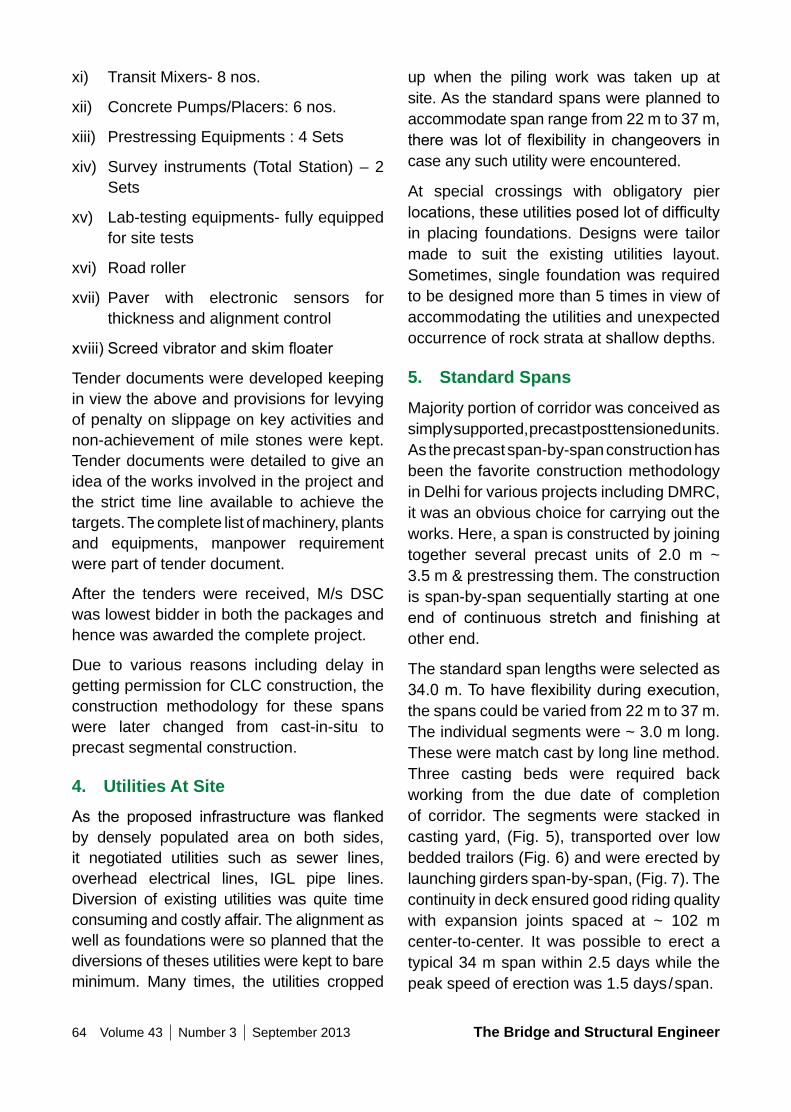
64 Volume 43 Number 3 September 2013 The Bridge and Structural Engineer
xi) Transit Mixers- 8 nos.
xii) Concrete Pumps/Placers: 6 nos.
xiii) Prestressing Equipments : 4 Sets
xiv) Survey instruments (Total Station) – 2 Sets
xv) Lab-testing equipments- fully equipped for site tests
xvi) Road roller
xvii) Paver with electronic sensors for thickness and alignment control
xviii)Screedvibratorandskimfloater
Tender documents were developed keeping in view the above and provisions for levying of penalty on slippage on key activities and non-achievement of mile stones were kept. Tender documents were detailed to give an idea of the works involved in the project and the strict time line available to achieve the targets. The complete list of machinery, plants and equipments, manpower requirement were part of tender document.
After the tenders were received, M/s DSC was lowest bidder in both the packages and hence was awarded the complete project.
Due to various reasons including delay in getting permission for CLC construction, the construction methodology for these spans were later changed from cast-in-situ to precast segmental construction.
4. Utilities At SiteAs the proposed infrastructure was flankedby densely populated area on both sides, it negotiated utilities such as sewer lines, overhead electrical lines, IGL pipe lines. Diversion of existing utilities was quite time consuming and costly affair. The alignment as well as foundations were so planned that the diversions of theses utilities were kept to bare minimum. Many times, the utilities cropped
up when the piling work was taken up at site. As the standard spans were planned to accommodate span range from 22 m to 37 m, therewas lot of flexibility in changeovers incase any such utility were encountered.
At special crossings with obligatory pier locations,theseutilitiesposedlotofdifficultyin placing foundations. Designs were tailor made to suit the existing utilities layout. Sometimes, single foundation was required to be designed more than 5 times in view of accommodating the utilities and unexpected occurrence of rock strata at shallow depths.
5. Standard Spans
Majority portion of corridor was conceived as simply supported, precast post tensioned units. As the precast span-by-span construction has been the favorite construction methodology in Delhi for various projects including DMRC, it was an obvious choice for carrying out the works. Here, a span is constructed by joining together several precast units of 2.0 m ~ 3.5 m & prestressing them. The construction is span-by-span sequentially starting at one end of continuous stretch and finishing atother end.
The standard span lengths were selected as 34.0m.Tohaveflexibilityduringexecution,the spans could be varied from 22 m to 37 m. The individual segments were ~ 3.0 m long. These were match cast by long line method. Three casting beds were required back working from the due date of completion of corridor. The segments were stacked in casting yard, (Fig. 5), transported over low bedded trailors (Fig. 6) and were erected by launching girders span-by-span, (Fig. 7). The continuity in deck ensured good riding quality with expansion joints spaced at ~ 102 m center-to-center. It was possible to erect a typical 34 m span within 2.5 days while the peak speed of erection was 1.5 days/span.
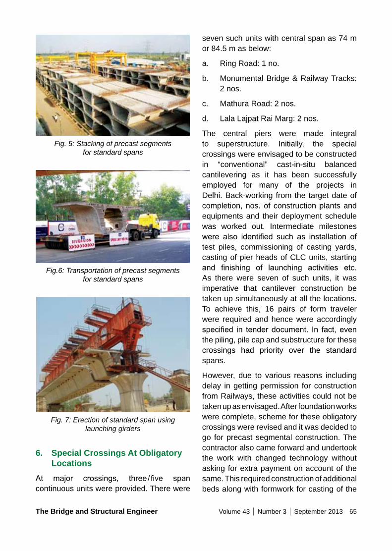
The Bridge and Structural Engineer Volume 43 Number 3 September 2013 65
Fig. 5: Stacking of precast segments for standard spans
Fig.6: Transportation of precast segments for standard spans
Fig. 7: Erection of standard span using launching girders
6. Special Crossings At obligatory Locations
At major crossings, three/five spancontinuous units were provided. There were
seven such units with central span as 74 m or 84.5 m as below:
a. Ring Road: 1 no.
b. Monumental Bridge & Railway Tracks: 2 nos.
c. Mathura Road: 2 nos.
d. Lala Lajpat Rai Marg: 2 nos.
The central piers were made integral to superstructure. Initially, the special crossings were envisaged to be constructed in “conventional” cast-in-situ balanced cantilevering as it has been successfully employed for many of the projects in Delhi. Back-working from the target date of completion, nos. of construction plants and equipments and their deployment schedule was worked out. Intermediate milestones were also identified such as installation oftest piles, commissioning of casting yards, casting of pier heads of CLC units, starting and finishing of launching activities etc.As there were seven of such units, it was imperative that cantilever construction be taken up simultaneously at all the locations. To achieve this, 16 pairs of form traveler were required and hence were accordingly specified in tenderdocument. In fact,eventhe piling, pile cap and substructure for these crossings had priority over the standard spans.
However, due to various reasons including delay in getting permission for construction from Railways, these activities could not be taken up as envisaged. After foundation works were complete, scheme for these obligatory crossings were revised and it was decided to go for precast segmental construction. The contractor also came forward and undertook the work with changed technology without asking for extra payment on account of the same. This required construction of additional beds along with formwork for casting of the
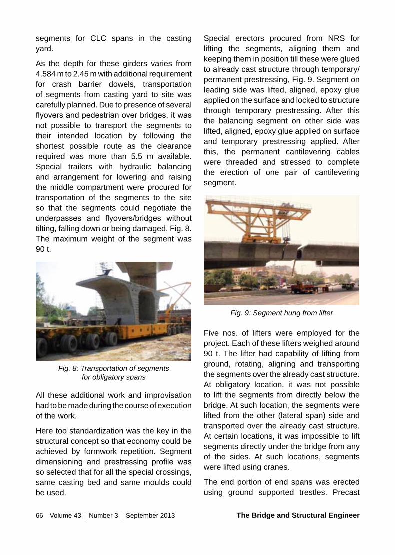
66 Volume 43 Number 3 September 2013 The Bridge and Structural Engineer
segments for CLC spans in the casting yard.
As the depth for these girders varies from 4.584 m to 2.45 m with additional requirement for crash barrier dowels, transportation of segments from casting yard to site was carefully planned. Due to presence of several flyoversandpedestrianoverbridges,itwasnot possible to transport the segments to their intended location by following the shortest possible route as the clearance required was more than 5.5 m available. Special trailers with hydraulic balancing and arrangement for lowering and raising the middle compartment were procured for transportation of the segments to the site so that the segments could negotiate the underpasses and flyovers/bridges withouttilting, falling down or being damaged, Fig. 8. The maximum weight of the segment was 90 t.
Fig. 8: Transportation of segments for obligatory spans
All these additional work and improvisation had to be made during the course of execution of the work.
Here too standardization was the key in the structural concept so that economy could be achieved by formwork repetition. Segment dimensioning and prestressing profile wasso selected that for all the special crossings, same casting bed and same moulds could be used.
Special erectors procured from NRS for lifting the segments, aligning them and keeping them in position till these were glued to already cast structure through temporary/permanent prestressing, Fig. 9. Segment on leading side was lifted, aligned, epoxy glue applied on the surface and locked to structure through temporary prestressing. After this the balancing segment on other side was lifted, aligned, epoxy glue applied on surface and temporary prestressing applied. After this, the permanent cantilevering cables were threaded and stressed to complete the erection of one pair of cantilevering segment.
Fig. 9: Segment hung from lifter
Five nos. of lifters were employed for the project. Each of these lifters weighed around 90 t. The lifter had capability of lifting from ground, rotating, aligning and transporting the segments over the already cast structure. At obligatory location, it was not possible to lift the segments from directly below the bridge. At such location, the segments were lifted from the other (lateral span) side and transported over the already cast structure. At certain locations, it was impossible to lift segments directly under the bridge from any of the sides. At such locations, segments were lifted using cranes.
The end portion of end spans was erected using ground supported trestles. Precast
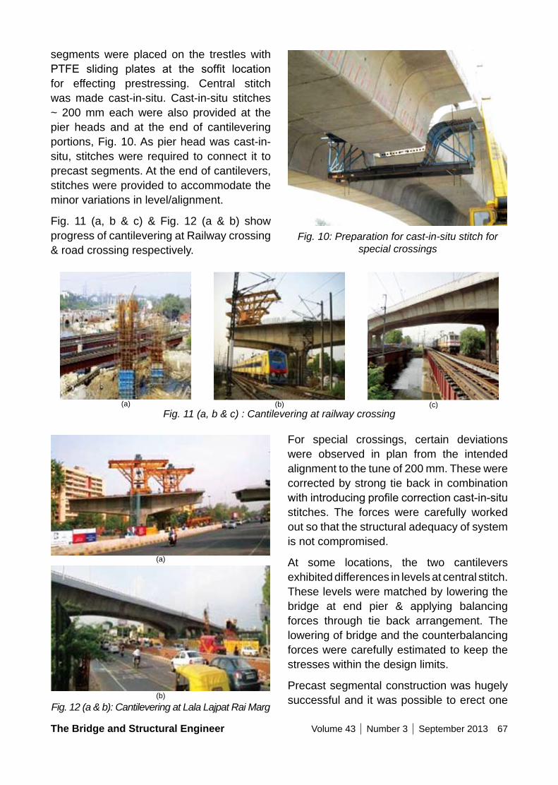
The Bridge and Structural Engineer Volume 43 Number 3 September 2013 67
segments were placed on the trestles with PTFE sliding plates at the soffit locationfor effecting prestressing. Central stitch was made cast-in-situ. Cast-in-situ stitches ~ 200 mm each were also provided at the pier heads and at the end of cantilevering portions, Fig. 10. As pier head was cast-in-situ, stitches were required to connect it to precast segments. At the end of cantilevers, stitches were provided to accommodate the minor variations in level/alignment.
Fig. 11 (a, b & c) & Fig. 12 (a & b) show progress of cantilevering at Railway crossing & road crossing respectively.
Fig. 10: Preparation for cast-in-situ stitch for special crossings
Fig. 11 (a, b & c) : Cantilevering at railway crossing
Fig. 12 (a & b): Cantilevering at Lala Lajpat Rai Marg
For special crossings, certain deviations were observed in plan from the intended alignment to the tune of 200 mm. These were corrected by strong tie back in combination withintroducingprofilecorrectioncast-in-situstitches. The forces were carefully worked out so that the structural adequacy of system is not compromised.
At some locations, the two cantilevers exhibited differences in levels at central stitch. These levels were matched by lowering the bridge at end pier & applying balancing forces through tie back arrangement. The lowering of bridge and the counterbalancing forces were carefully estimated to keep the stresses within the design limits.
Precast segmental construction was hugely successful and it was possible to erect one
(a) (b) (c)
(a)
(b)

68 Volume 43 Number 3 September 2013 The Bridge and Structural Engineer
segment per day thus achieving progress of 6.0 m construction of viaduct per day.
7. Railway CrossingThe erection of the spans over the railway tracks presented special difficulties as allactivities above them had to be restricted to alternate days for two hours only starting at mid-night, when the ‘block-time’ could be made available. Within the two hour time, segment was to be brought in position, aligned, Epoxy glue applied & temporary prestressing done. After this, the permanent stressing was done in next block time. Also the threading of prestressing tendons over long lengths and tensioning them was not an easy task at site within the available block time.
Thedesignwasspecificallymadetoensurethat one end stressing of tendons was possible with the live end located on side spans. i.e. away from the railway tracks.
While substructure work was being done in the railway area for the obligatory span, Railway sprang another surprise when they started the work of box pushing at the same location for constructing an underpass through the railway embankment and asked PWD to create a bridge over the area and carry out casting of in-situ span over it leaving the area below clear for box pushing work (Fig. 13). Railway ‘tagged’ this underpass also as CWG related project.
Fig. 13: Box pushing underneath the truss structure of 35 m span at railway crossing
This necessitated design and fabrication of huge trusses of 35 m span on emergency basis. This further increased the scope of work in railway area and disrupted the original plan of work. To carryout both the works simultaneously an elevated platform had to be constructed over a span of 25 meter for construction of 25 m long cost-in-situ span between two obligatory spans of 85 meters on either side over the railway tracks and Barahpulla road. This further delayed the construction work in railway area by about a month.
8. FoundationThe complete structure is founded on 1200 diameter bored cast-in-situ piles. Pile layout has been decided keeping in view the utilities requiring co-ordination with site and improvisation in designs with progress of work at site. As the complete alignment lies in Nalla, the complete foundation works have been carried out below the drain bed. To guard against infringement with existing underground utilities, probing was carried out along the alignment length prior to selection of pier locations.
Despite this, at many locations foundations had to redesigned due to presence of unchartered or hidden utilities encountered during construction of foundation works.
During tender development stage, as per geotechnical investigation, no rock was envisaged for the complete alignment. However, during execution, rock was encountered at and around Railway track crossing for 12 piers. This called for revision in designs of substructure with effect on continuous unit superstructure design. The problem was compounded by presence of several utilities in that very zone.
9. Concluding RemarksIt is one of the major Commonwealth games
The Bridge and Structural Engineer Volume 43 Number 3 September 2013 69
related projects taken in Delhi. The work was executed round the clock throughout. Everyone involved with the project toiled continuously to make it a success story. At site, work was carried out continuously whether it was chilly & foggy winter nights or hot & dusty summer afternoons. Delhi witnessed one of the heaviest monsoons during 2010 when there was hardly any clear day from Mid July till almost end of September. All the top functionaries of Government of Delhi & Government of India started panicking after July 2010. All their doubts were put to rest when the work was completed on 23rd September 2010 and trial run of buses for CWG 2010 started on this road. It was the crucial link between Games Village and Jawahar Lal Nehru stadium to transport athletes and officials. Subsequently, it hasturned out to be a very useful link between East Delhi to South Delhi and has reduced congestion on Ring Road at Ashram and Bhairon Marg. The corridor is being extended to INA in phase II.
The execution of project has been an arduous journey through various challenges. The successful completion of project has demonstrated the exceptional grit & determination of Engineers. Barapullah elevated road is a record for construction in severely constrained timeline in hostile terrain along with inherent complications of working in a Delhi.
10. Credits• Owner : Public Works Department,
Government of NCT of Delhi• Contractor : M/s DSC Limited• Feasibility & Highway Consultant
M/s VKS Infratech• Proof Consultant : M/s Construma
Consultancy Private Ltd.• Structural Design Consultant : M/s
Tandon Consultant Private Ltd Client Public Works Department, Government of NCT of Delhi
Concrete (m3 ) : 200000 cum
Service Date : 23.09.2010
Awards Received by Project1. Central Public Works Department – The
Arch Shaped Suspended Pedestrian Bridge on Barapullah Road near Jawaharlal Nehru Stadium has been awarded a special prize for Innovation & Design
2. Indian Building Congress Award for Excellence in Built Environment, 2011
3. Indian Concrete Institute Award for Prestressed Concrete Structure in the Country, 2011
4. Construction Industry Development Council Vishwakarma Award 2011 Under the Category ‘Best Project’
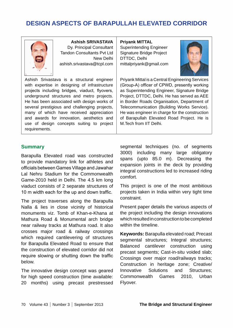
70 Volume 43 Number 3 September 2013 The Bridge and Structural Engineer
DESIGn ASPECTS oF BARAPULLAH ELEVATED CoRRIDoR
Ashish SRIVASTAVADy. Principal Consultant
Tandon Consultants Pvt LtdNew Delhi
Ashish Srivastava is a structural engineer with expertise in designing of infrastructure projects including bridges, viaduct, flyovers,underground structures and metro projects. He has been associated with design works of several prestigious and challenging projects, many of which have received appreciation and awards for innovation, aesthetics and use of design concepts suiting to project requirements.
Priyank MITTAL Superintending Engineer Signature Bridge Project DTTDC, Delhi [email protected]
Priyank Mittal is a Central Engineering Services (Group-A)officerofCPWD,presentlyworkingas Superintending Engineer, Signature Bridge Project, DTTDC, Delhi. He has served as AEE in Border Roads Organisation, Department of Telecommunication (Building Works Service). He was engineer in charge for the construction of Barapullah Elevated Road Project. He is M.Tech from IIT Delhi.
SummaryBarapulla Elevated road was constructed to provide mandatory link for athletes and officialsbetweenGamesVillageandJawaharLal Nehru Stadium for the Commonwealth Game-2010 held in Delhi. The 4.5 km long viaduct consists of 2 separate structures of 10mwidtheachfortheupanddowntraffic.
The project traverses along the Barapulla Nalla & lies in close vicinity of historical monuments viz. Tomb of Khan-e-Khana at Mathura Road & Monumental arch bridge near railway tracks at Mathura road. It also crosses major road & railway crossings which required cantilevering of structures for Barapulla Elevated Road to ensure that the construction of elevated corridor did not require slowingor shuttingdown the trafficbelow.
The innovative design concept was geared for high speed construction (time available: 20 months) using precast prestressed
segmental techniques (no. of segments 3000) including many large obligatory spans (upto 85.0 m). Decreasing the expansion joints in the deck by providing integral constructions led to increased riding comfort.
This project is one of the most ambitious projects taken in India within very tight time constraint.
Present paper details the various aspects of the project including the design innovations which resulted in construction to be completed within the timeline.
Keywords: Barapulla elevated road; Precast segmental structures; Integral structures; Balanced cantilever construction using precast segments; Cast-in-situ voided slab; Crossings over major road/railways tracks; Construction in heritage zone; Creative/Innovative Solutions and Structures; Commonwealth Games 2010, Urban Flyover.
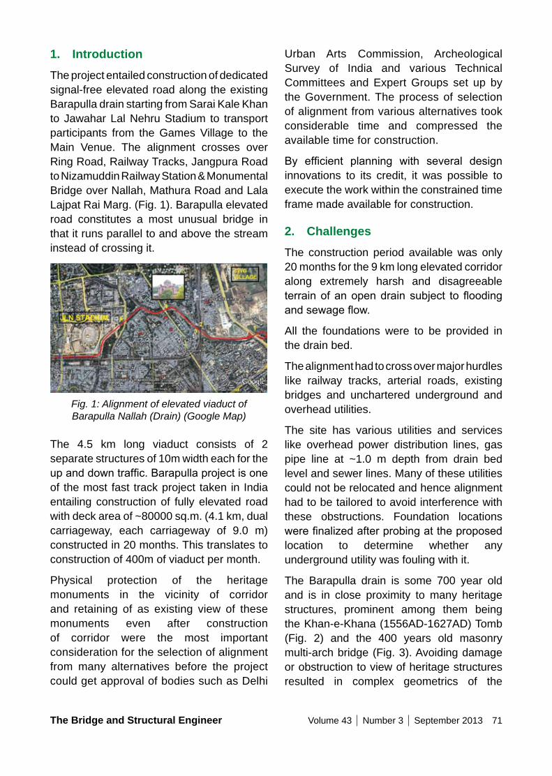
The Bridge and Structural Engineer Volume 43 Number 3 September 2013 71
1. IntroductionThe project entailed construction of dedicated signal-free elevated road along the existing Barapulla drain starting from Sarai Kale Khan to Jawahar Lal Nehru Stadium to transport participants from the Games Village to the Main Venue. The alignment crosses over Ring Road, Railway Tracks, Jangpura Road to Nizamuddin Railway Station & Monumental Bridge over Nallah, Mathura Road and Lala Lajpat Rai Marg. (Fig. 1). Barapulla elevated road constitutes a most unusual bridge in that it runs parallel to and above the stream instead of crossing it.
Fig. 1: Alignment of elevated viaduct of Barapulla Nallah (Drain) (Google Map)
The 4.5 km long viaduct consists of 2 separate structures of 10m width each for the upanddowntraffic.Barapullaprojectisoneof the most fast track project taken in India entailing construction of fully elevated road with deck area of ~80000 sq.m. (4.1 km, dual carriageway, each carriageway of 9.0 m) constructed in 20 months. This translates to construction of 400m of viaduct per month.
Physical protection of the heritage monuments in the vicinity of corridor and retaining of as existing view of these monuments even after construction of corridor were the most important consideration for the selection of alignment from many alternatives before the project could get approval of bodies such as Delhi
Urban Arts Commission, Archeological Survey of India and various Technical Committees and Expert Groups set up by the Government. The process of selection of alignment from various alternatives took considerable time and compressed the available time for construction.
By efficient planning with several designinnovations to its credit, it was possible to execute the work within the constrained time frame made available for construction.
2. ChallengesThe construction period available was only 20 months for the 9 km long elevated corridor along extremely harsh and disagreeable terrainofanopendrainsubject tofloodingandsewageflow.
All the foundations were to be provided in the drain bed.
The alignment had to cross over major hurdles like railway tracks, arterial roads, existing bridges and unchartered underground and overhead utilities.
The site has various utilities and services like overhead power distribution lines, gas pipe line at ~1.0 m depth from drain bed level and sewer lines. Many of these utilities could not be relocated and hence alignment had to be tailored to avoid interference with these obstructions. Foundation locations werefinalizedafterprobingattheproposed location to determine whether any underground utility was fouling with it.
The Barapulla drain is some 700 year old and is in close proximity to many heritage structures, prominent among them being the Khan-e-Khana (1556AD-1627AD) Tomb (Fig. 2) and the 400 years old masonry multi-arch bridge (Fig. 3). Avoiding damage or obstruction to view of heritage structures resulted in complex geometrics of the
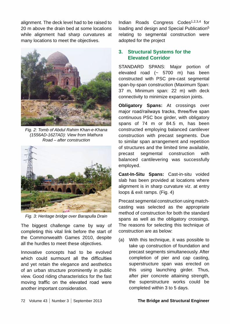
72 Volume 43 Number 3 September 2013 The Bridge and Structural Engineer
Indian Roads Congress Codes1,2,3,4 for loading and design and Special Publication5 relating to segmental construction were adopted for the project
3. Structural Systems for the Elevated Corridor
STANDARD SPANS: Major portion of elevated road (~ 5700 m) has been constructed with PSC pre-cast segmental span-by-span construction (Maximum Span: 37 m, Minimum span: 22 m) with deck connectivity to minimize expansion joints.
obligatory Spans: At crossings over major road/railways tracks, three/fivespancontinuous PSC box girder, with obligatory spans of 74 m or 84.5 m, has been constructed employing balanced cantilever construction with precast segments. Due to similar span arrangement and repetition of structures and the limited time available, precast segmental construction with balanced cantilevering was successfully employed.
Cast-In-Situ Spans: Cast-in-situ voided slab has been provided at locations where alignment is in sharp curvature viz. at entry loops & exit ramps. (Fig. 4)
Precast segmental construction using match-casting was selected as the appropriate method of construction for both the standard spans as well as the obligatory crossings. The reasons for selecting this technique of construction are as below:
(a) With this technique, it was possible to take up construction of foundation and precast segments simultaneously. After completion of pier and cap casting, superstructure span was erected on this using launching girder. Thus, after pier concrete attaining strength, the superstructure works could be completed within 3 to 5 days.
alignment. The deck level had to be raised to 20 m above the drain bed at some locations while alignment had sharp curvatures at many locations to meet the objectives.
Fig. 2: Tomb of Abdul Rahim Khan-e-Khana (1556AD-1627AD): View from Mathura
Road – after construction
Fig. 3: Heritage bridge over Barapulla Drain
The biggest challenge came by way of completing this vital link before the start of the Commonwealth Games 2010, despite all the hurdles to meet these objectives.
Innovative concepts had to be evolved which could surmount all the difficultiesand yet retain the elegance and aesthetics of an urban structure prominently in public view. Good riding characteristics for the fast moving traffic on the elevated road wereanother important consideration.
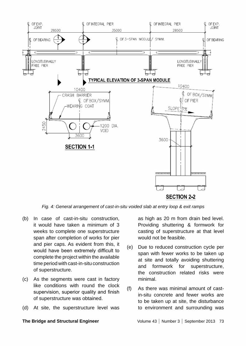
The Bridge and Structural Engineer Volume 43 Number 3 September 2013 73
as high as 20 m from drain bed level. Providing shuttering & formwork for casting of superstructure at that level would not be feasible.
(e) Due to reduced construction cycle per span with fewer works to be taken up at site and totally avoiding shuttering and formwork for superstructure, the construction related risks were minimal.
(f) As there was minimal amount of cast-in-situ concrete and fewer works are to be taken up at site, the disturbance to environment and surrounding was
(b) In case of cast-in-situ construction, it would have taken a minimum of 3 weeks to complete one superstructure span after completion of works for pier and pier caps. As evident from this, it wouldhavebeenextremelydifficult tocomplete the project within the available time period with cast-in-situ construction of superstructure.
(c) As the segments were cast in factory like conditions with round the clock supervision,superiorqualityandfinishof superstructure was obtained.
(d) At site, the superstructure level was
Fig. 4: General arrangement of cast-in-situ voided slab at entry loop & exit ramps
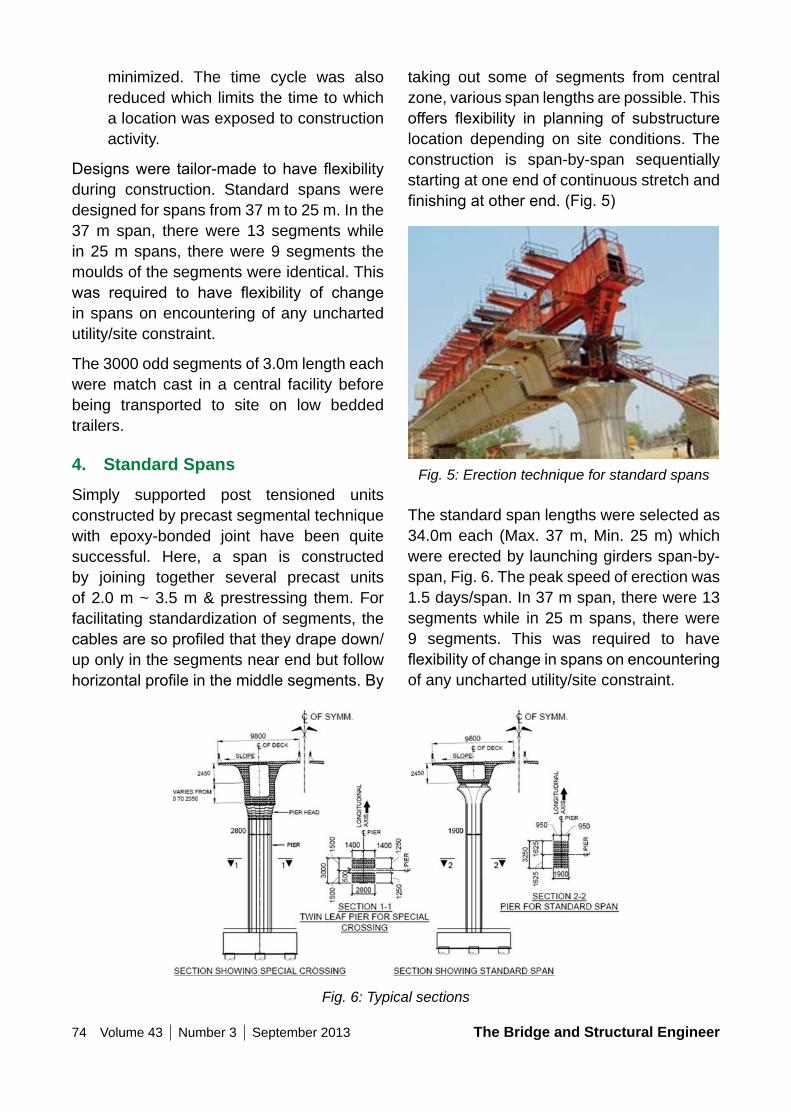
74 Volume 43 Number 3 September 2013 The Bridge and Structural Engineer
taking out some of segments from central zone, various span lengths are possible. This offers flexibility in planning of substructurelocation depending on site conditions. The construction is span-by-span sequentially starting at one end of continuous stretch and finishingatotherend.(Fig.5)
Fig. 5: Erection technique for standard spans
The standard span lengths were selected as 34.0m each (Max. 37 m, Min. 25 m) which were erected by launching girders span-by-span, Fig. 6. The peak speed of erection was 1.5 days/span. In 37 m span, there were 13 segments while in 25 m spans, there were 9 segments. This was required to have flexibilityofchangeinspansonencounteringof any uncharted utility/site constraint.
minimized. The time cycle was also reduced which limits the time to which a location was exposed to construction activity.
Designswere tailor-made tohaveflexibilityduring construction. Standard spans were designed for spans from 37 m to 25 m. In the 37 m span, there were 13 segments while in 25 m spans, there were 9 segments the moulds of the segments were identical. This was required to have flexibility of changein spans on encountering of any uncharted utility/site constraint.
The 3000 odd segments of 3.0m length each were match cast in a central facility before being transported to site on low bedded trailers.
4. Standard SpansSimply supported post tensioned units constructed by precast segmental technique with epoxy-bonded joint have been quite successful. Here, a span is constructed by joining together several precast units of 2.0 m ~ 3.5 m & prestressing them. For facilitating standardization of segments, the cablesaresoprofiledthattheydrapedown/up only in the segments near end but follow horizontalprofileinthemiddlesegments.By
Fig. 6: Typical sections
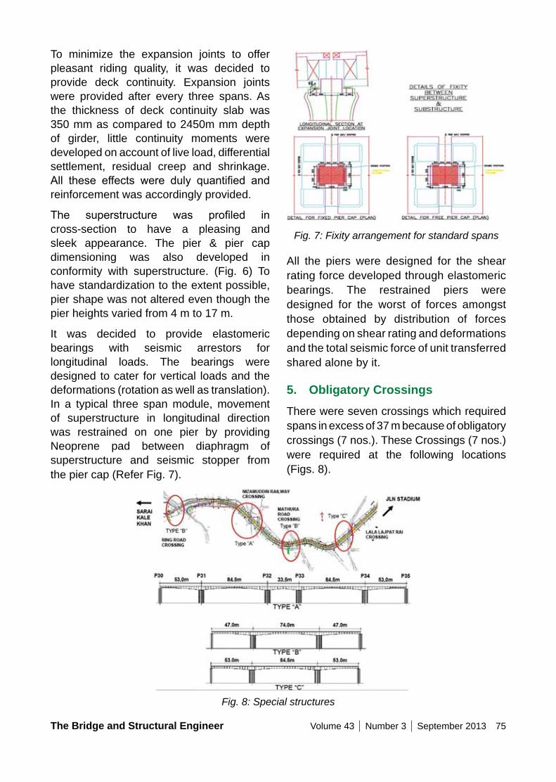
The Bridge and Structural Engineer Volume 43 Number 3 September 2013 75
Fig. 7: Fixity arrangement for standard spans
All the piers were designed for the shear rating force developed through elastomeric bearings. The restrained piers were designed for the worst of forces amongst those obtained by distribution of forces depending on shear rating and deformations and the total seismic force of unit transferred shared alone by it.
5. obligatory CrossingsThere were seven crossings which required spans in excess of 37 m because of obligatory crossings (7 nos.). These Crossings (7 nos.) were required at the following locations (Figs. 8).
To minimize the expansion joints to offer pleasant riding quality, it was decided to provide deck continuity. Expansion joints were provided after every three spans. As the thickness of deck continuity slab was 350 mm as compared to 2450m mm depth of girder, little continuity moments were developed on account of live load, differential settlement, residual creep and shrinkage. All these effects were duly quantified andreinforcement was accordingly provided.
The superstructure was profiled incross-section to have a pleasing and sleek appearance. The pier & pier cap dimensioning was also developed in conformity with superstructure. (Fig. 6) To have standardization to the extent possible, pier shape was not altered even though the pier heights varied from 4 m to 17 m.
It was decided to provide elastomeric bearings with seismic arrestors for longitudinal loads. The bearings were designed to cater for vertical loads and the deformations (rotation as well as translation). In a typical three span module, movement of superstructure in longitudinal direction was restrained on one pier by providing Neoprene pad between diaphragm of superstructure and seismic stopper from the pier cap (Refer Fig. 7).
Fig. 8: Special structures
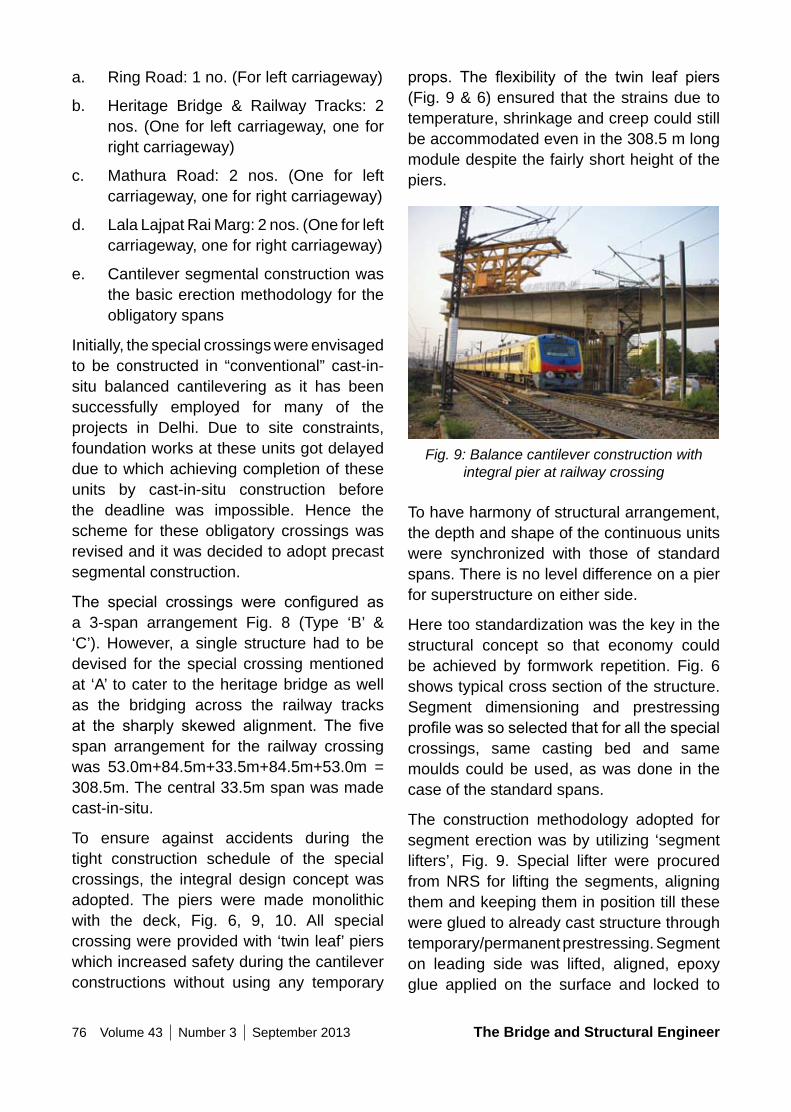
76 Volume 43 Number 3 September 2013 The Bridge and Structural Engineer
props. The flexibility of the twin leaf piers(Fig. 9 & 6) ensured that the strains due to temperature, shrinkage and creep could still be accommodated even in the 308.5 m long module despite the fairly short height of the piers.
Fig. 9: Balance cantilever construction with integral pier at railway crossing
To have harmony of structural arrangement, the depth and shape of the continuous units were synchronized with those of standard spans. There is no level difference on a pier for superstructure on either side.
Here too standardization was the key in the structural concept so that economy could be achieved by formwork repetition. Fig. 6 shows typical cross section of the structure. Segment dimensioning and prestressing profilewassoselectedthatforallthespecialcrossings, same casting bed and same moulds could be used, as was done in the case of the standard spans.
The construction methodology adopted for segment erection was by utilizing ‘segment lifters’, Fig. 9. Special lifter were procured from NRS for lifting the segments, aligning them and keeping them in position till these were glued to already cast structure through temporary/permanent prestressing. Segment on leading side was lifted, aligned, epoxy glue applied on the surface and locked to
a. Ring Road: 1 no. (For left carriageway)
b. Heritage Bridge & Railway Tracks: 2 nos. (One for left carriageway, one for right carriageway)
c. Mathura Road: 2 nos. (One for left carriageway, one for right carriageway)
d. Lala Lajpat Rai Marg: 2 nos. (One for left carriageway, one for right carriageway)
e. Cantilever segmental construction was the basic erection methodology for the obligatory spans
Initially, the special crossings were envisaged to be constructed in “conventional” cast-in-situ balanced cantilevering as it has been successfully employed for many of the projects in Delhi. Due to site constraints, foundation works at these units got delayed due to which achieving completion of these units by cast-in-situ construction before the deadline was impossible. Hence the scheme for these obligatory crossings was revised and it was decided to adopt precast segmental construction.
The special crossings were configured asa 3-span arrangement Fig. 8 (Type ‘B’ & ‘C’). However, a single structure had to be devised for the special crossing mentioned at ‘A’ to cater to the heritage bridge as well as the bridging across the railway tracks at the sharply skewed alignment. The fivespan arrangement for the railway crossing was 53.0m+84.5m+33.5m+84.5m+53.0m = 308.5m. The central 33.5m span was made cast-in-situ.
To ensure against accidents during the tight construction schedule of the special crossings, the integral design concept was adopted. The piers were made monolithic with the deck, Fig. 6, 9, 10. All special crossing were provided with ‘twin leaf’ piers which increased safety during the cantilever constructions without using any temporary
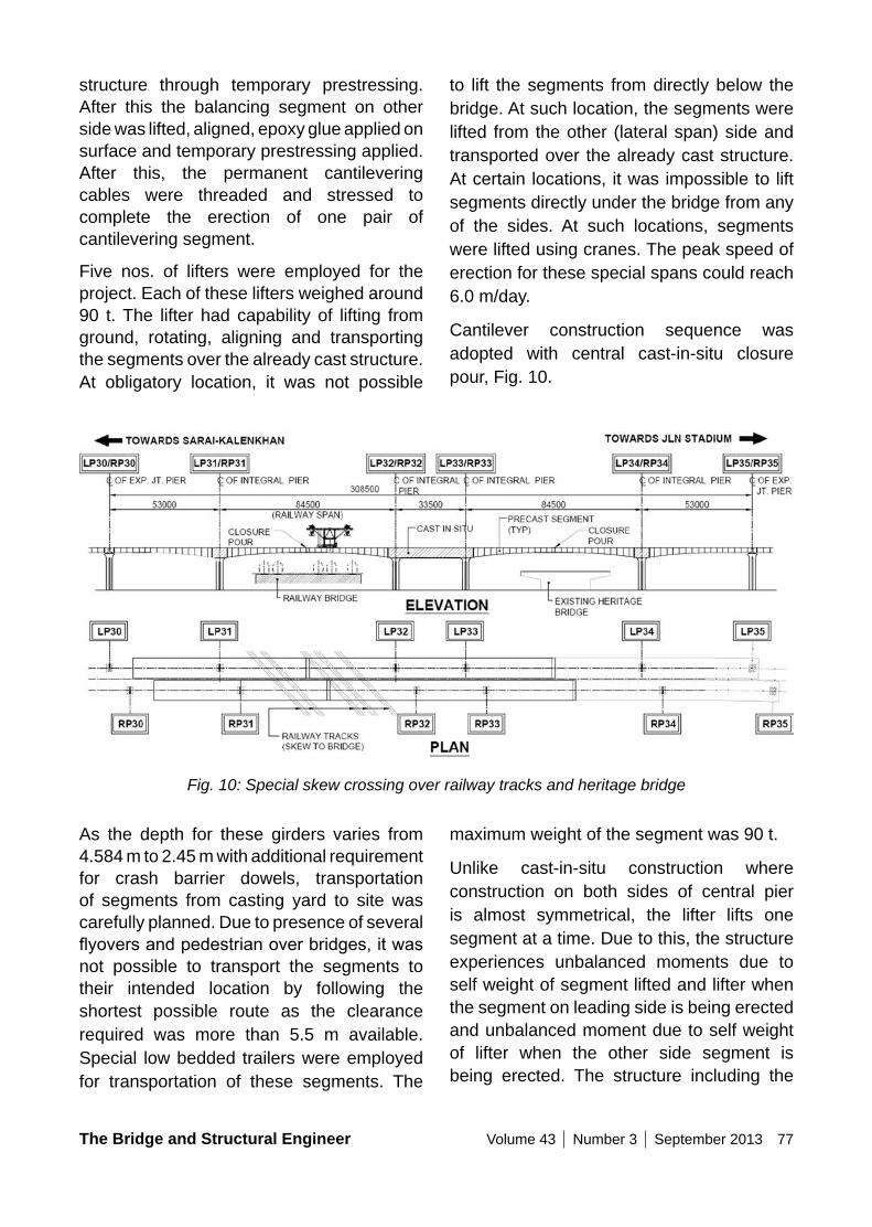
The Bridge and Structural Engineer Volume 43 Number 3 September 2013 77
to lift the segments from directly below the bridge. At such location, the segments were lifted from the other (lateral span) side and transported over the already cast structure. At certain locations, it was impossible to lift segments directly under the bridge from any of the sides. At such locations, segments were lifted using cranes. The peak speed of erection for these special spans could reach 6.0 m/day.
Cantilever construction sequence was adopted with central cast-in-situ closure pour, Fig. 10.
structure through temporary prestressing. After this the balancing segment on other side was lifted, aligned, epoxy glue applied on surface and temporary prestressing applied. After this, the permanent cantilevering cables were threaded and stressed to complete the erection of one pair of cantilevering segment.
Five nos. of lifters were employed for the project. Each of these lifters weighed around 90 t. The lifter had capability of lifting from ground, rotating, aligning and transporting the segments over the already cast structure. At obligatory location, it was not possible
Fig. 10: Special skew crossing over railway tracks and heritage bridge
As the depth for these girders varies from 4.584 m to 2.45 m with additional requirement for crash barrier dowels, transportation of segments from casting yard to site was carefully planned. Due to presence of several flyoversandpedestrianoverbridges,itwasnot possible to transport the segments to their intended location by following the shortest possible route as the clearance required was more than 5.5 m available. Special low bedded trailers were employed for transportation of these segments. The
maximum weight of the segment was 90 t.
Unlike cast-in-situ construction where construction on both sides of central pier is almost symmetrical, the lifter lifts one segment at a time. Due to this, the structure experiences unbalanced moments due to self weight of segment lifted and lifter when the segment on leading side is being erected and unbalanced moment due to self weight of lifter when the other side segment is being erected. The structure including the
78 Volume 43 Number 3 September 2013 The Bridge and Structural Engineer
at one support. Transverse restraint was provided at all supports.
POT-PTFE bearings were adopted for the end piers of the special crossings, with no bearings being necessary for all the other piers where the deck was made integral to the ‘twin leaf’ piers. The design concepts were such that the expansion joints were minimized. These measures ensured that during the service life, inspection & maintenance requirements would be reduced to a minimum.
Bored cast-in-situ piles of 1.2 m dia using hydraulic rotary rigs were adopted as foundations. Working with heavy equipments in the drain bed given the unfavourable environment was quite precarious, made more so with the unseasonal incessant rains.
Anti-carbonation coating was recommended for the structure due its location in severe conditions of exposure. This is in addition to other measures taken for durability, such as increased reinforcement cover, higher concrete grade and reduced water-cement ratio.
7. Concluding RemarksIt is one of the major Commonwealth games related projects taken inDelhi. By efficientplanning with several design innovations to its credit, it was possible to execute the work within the constrained time frame made available for construction. Its highlights can be summarized as follows:
i. Compressed contract period of 20 months for constructing 9km bridge length.
ii. Physical protection and visual facilitation of the archeological monuments in the vicinity of the alignment.
substructure and foundation was designed and detailed for this. Part counterbalancing was affected by placing segment at about ~ 12m on the following side.
The end portion of end spans was erected using ground supported trestles. Precast segments were placed on the trestles with PTFE sliding plates at the soffit locationfor effecting prestressing. Central stitch was made cast-in-situ. Cast-in-situ stitches ~ 200 mm each were also provided at the pier heads and at the end of cantilevering portions. As pier head was cast-in-situ, stitches were required to connect it to precast segments. At the end of cantilevers, stitches were provided to accommodate the minor variations in level/alignment.
The erection of the spans over the railway tracks, Fig. 9 & 10, presented special difficultiesasallactivitiesabovethemhadtobe restricted to alternate days for two hours only starting at mid-night, when the ‘block-time’ could be made available. The design was specifically made to ensure that oneend stressing of tendons was possible with the live end located on side spans. i.e., away from the railway tracks. Also the threading of prestressing tendons over long lengths and tensioning them was not an easy task at site.
6. other Important Aspects of Project
Delhi is located in a fairly high seismic zone, i.e., zone 4, whereas zone 5 is the highest in the country. Response spectrum analysis in accordance with the Indian Roads Congress code was carried out. Ductile detailing was done to ensure enhanced resistance during severe ground shaking.
Elastomeric bearings were adopted for the standard spans, with longitudinal restraint
The Bridge and Structural Engineer Volume 43 Number 3 September 2013 79
Awards Received By Project1. Central Public Works Department – The
Arch Shaped Suspended Pedestrian Bridge on Barapullah Road near Jawaharlal Nehru Stadium has been awarded a special prize for Innovation & Design
2. Indian Building Congress Award for Excellence in Built Environment, 2011
3. Indian Concrete Institute Award for Prestressed Concrete Structure in the Country, 2011
4. Construction Industry Development Council Vishwakarma Award 2011 Under the Category ‘Best Project’
References1. IRC:6-2010–StandardSpecifications
and Code of Practice for Road Bridges Section II: Load & Stresses
2. IRC : 18-2000 – Design Criteria for Prestressed Concrete Road Bridges (Post-Tensioned Concrete)
3. IRC:21-2000–StandardSpecificationsand Code of Practice for Road Bridges Section III: Cement Concrete (Plan and Reinforced)
4. IRC:78-2000–StandardSpecificationsand Code of Practice for Road Bridges Section VII: Foundation & Substructure
5. IRC : SP:65-2010 – Guidelines for Design and Construction of SegmentalBridge
iii. Alignment along extremely harsh and disagreeable terrain of open drain subjectedtofloodingandsewageflow.
iv. Major crossovers including railway tracks, existing bridges, arterial roads, unchartered underground and overhead utilities.
v. Completing the vital road link before the start of the Commonwealth Games 2010.
8. AcknowledgementThe authors would like to express their sincere thanks to Er. Sarvagya Srivastava, Project Manager, Er. V K Singh, Executive Engineer, Er. Akhilesh Kumar & Er. J P Mishra, Assistant Engineer, Public Works Department, Govt. of Delhi, all of whom made significant contributions in the successfulimplementation of this prestigious project.
9. Credits• Client : Public Works Department,
Government of NCT of Delhi
• Contractor : M/s DSC Limited
• Feasibility & Highway Consultant M/s VKS Infratech
• Proof Consultant : M/s. Construma Consultancy Private Ltd.
• Prime Consultant : M/s. Tandon Consultant Private Ltd
80 Volume 43 Number 3 September 2013 The Bridge and Structural Engineer
ConSIDERATIonS FoR REInFoRCED SoIL WALLS In URBAn FLyoVERS
Rajiv GoEL Managing Director Earthcon Systems India Pvt Ltd New Delhi, INDIA [email protected]
Rajiv Goel, an alumnus of BITS, Pilani (B.E. Civil, 1984-88) and IIT, Delhi (M. Tech., 1992-1994) is an active member of IRC and ING-IABSE. After serving with NITHE for about 4 years he joined M/s Tandon Consultants Pvt. Ltd. (TCPL) at Delhi in the year 1995. He is currently the Managing Director of Earthcon Systems (I) Pvt. Ltd. and apart from being a solution provider to the Highway Contractors, he is in active discussion with the fraternity through papers and presentations at NITHE, IRC and ING-IABSE.
Summary
RSW is an internally stabilized composite engineered mass and is being used for construction of approaches of flyovers/ROBs in a big way. In urban context RSW has the principal advantage of aesthetics and minimizing land requirements apart from many inherent advantages like better seismic performance and economy. This is also a favorable method for faster construction.
Many aspects like reinforcing elements’ types, facia types, design philosophies and appurtenances are discussed herein. A separate section has also been devoted to abutment-RSW interface as this is one aspectwhichdefinitelyrequirestheattentionof viaduct designers.
Keywords
Reinforced Soil Walls, Urban Flyovers, FlyoverAppurtenances,Select granular fill,GI Steel Strips, Metallic Bar Mats, Welded / Twisted Coated Wire Mesh, Polymeric Grids: Geogrids, Woven Geo-Textile, Geo-Strap/Geo-Tie, Modular Blocks, Discrete Facia
Panels, Hybrid blockpanel facia, Abutment Interface, MSEW.
1. Introduction1.1 India has undertaken large
infrastructure up-gradation projects and Reinforced Soil Walls (RSW) are being widely used for constructing high embankments due to various reasons such as limited right of roadway; to minimize land acquisition, poor founding soil conditions, aesthetics, economy considerations & ease of construction etc. The quantum of work has increased many folds and contractors have to choose from various available alternates by evaluating economy, aesthetic, durability and speed of construction.
1.2 RSW is an internally stabilized composite engineered mass; consisting of selected backfill,soil reinforcingelementsandanon-structural/optional facia.
1.3 In urban context the major advantages of RSW are aesthetics, limited site
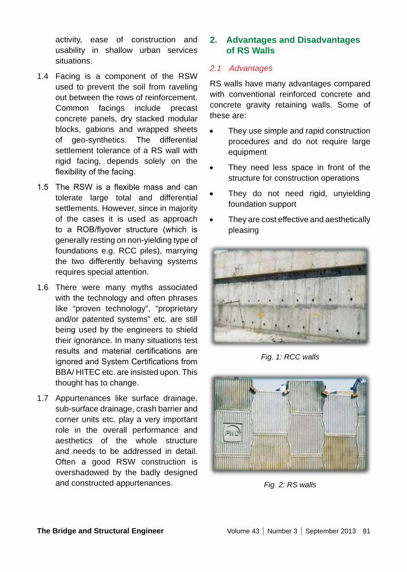
The Bridge and Structural Engineer Volume 43 Number 3 September 2013 81
2. Advantages and Disadvantages of RS Walls
2.1 Advantages
RS walls have many advantages compared with conventional reinforced concrete and concrete gravity retaining walls. Some of these are:
• They use simple and rapid construction procedures and do not require large equipment
• They need less space in front of the structure for construction operations
• They do not need rigid, unyielding foundation support
• They are cost effective and aesthetically pleasing
Fig. 1: RCC walls
Fig. 2: RS walls
activity, ease of construction and usability in shallow urban services situations.
1.4 Facing is a component of the RSW used to prevent the soil from raveling out between the rows of reinforcement. Common facings include precast concrete panels, dry stacked modular blocks, gabions and wrapped sheets of geo-synthetics. The differential settlement tolerance of a RS wall with rigid facing, depends solely on the flexibilityofthefacing.
1.5 The RSW is a flexiblemass and cantolerate large total and differential settlements. However, since in majority of the cases it is used as approach to a ROB/flyover structure (which isgenerally resting on non-yielding type of foundations e.g. RCC piles), marrying the two differently behaving systems requires special attention.
1.6 There were many myths associated with the technology and often phrases like “proven technology”, “proprietary and/or patented systems” etc. are still being used by the engineers to shield their ignorance. In many situations test results and material certifications areignoredandSystemCertificationsfromBBA/ HITEC etc. are insisted upon. This thought has to change.
1.7 Appurtenances like surface drainage, sub-surface drainage, crash barrier and corner units etc. play a very important role in the overall performance and aesthetics of the whole structure and needs to be addressed in detail. Often a good RSW construction is overshadowed by the badly designed and constructed appurtenances.
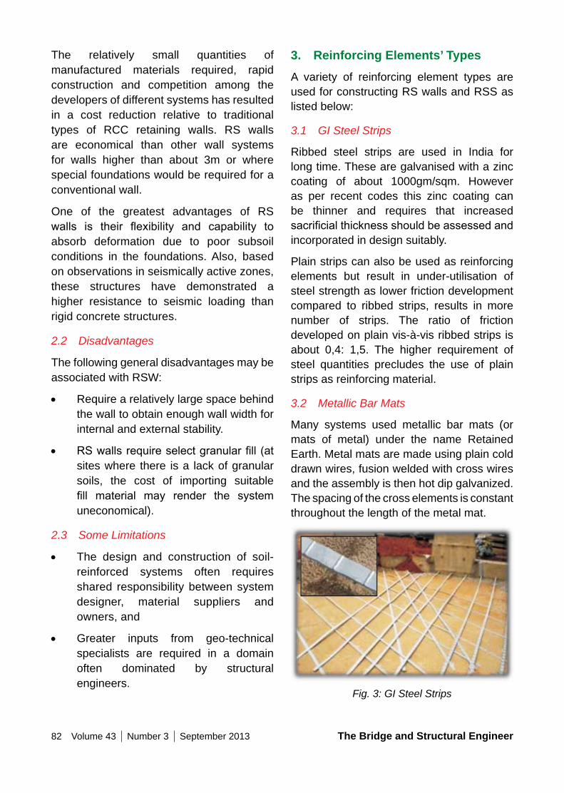
82 Volume 43 Number 3 September 2013 The Bridge and Structural Engineer
3. Reinforcing Elements’ TypesA variety of reinforcing element types are used for constructing RS walls and RSS as listed below:
3.1 GI Steel Strips
Ribbed steel strips are used in India for long time. These are galvanised with a zinc coating of about 1000gm/sqm. However as per recent codes this zinc coating can be thinner and requires that increased sacrificialthicknessshouldbeassessedandincorporated in design suitably.
Plain strips can also be used as reinforcing elements but result in under-utilisation of steel strength as lower friction development compared to ribbed strips, results in more number of strips. The ratio of friction developed on plain vis-à-vis ribbed strips is about 0,4: 1,5. The higher requirement of steel quantities precludes the use of plain strips as reinforcing material.
3.2 Metallic Bar Mats
Many systems used metallic bar mats (or mats of metal) under the name Retained Earth. Metal mats are made using plain cold drawn wires, fusion welded with cross wires and the assembly is then hot dip galvanized. The spacing of the cross elements is constant throughout the length of the metal mat.
Fig. 3: GI Steel Strips
The relatively small quantities of manufactured materials required, rapid construction and competition among the developers of different systems has resulted in a cost reduction relative to traditional types of RCC retaining walls. RS walls are economical than other wall systems for walls higher than about 3m or where special foundations would be required for a conventional wall.
One of the greatest advantages of RS walls is their flexibility and capability toabsorb deformation due to poor subsoil conditions in the foundations. Also, based on observations in seismically active zones, these structures have demonstrated a higher resistance to seismic loading than rigid concrete structures.
2.2 Disadvantages
The following general disadvantages may be associated with RSW:
• Require a relatively large space behind the wall to obtain enough wall width for internal and external stability.
• RSwallsrequireselectgranularfill(atsites where there is a lack of granular soils, the cost of importing suitable fill material may render the systemuneconomical).
2.3 Some Limitations
• The design and construction of soil-reinforced systems often requires shared responsibility between system designer, material suppliers and owners, and
• Greater inputs from geo-technical specialists are required in a domain often dominated by structural engineers.
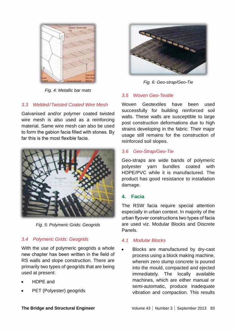
The Bridge and Structural Engineer Volume 43 Number 3 September 2013 83
Fig. 6: Geo-strap/Geo-Tie
3.5 Woven Geo-Textile
Woven Geotextiles have been used successfully for building reinforced soil walls. These walls are susceptible to large post construction deformations due to high strains developing in the fabric. Their major usage still remains for the construction of reinforced soil slopes.
3.6 Geo-Strap/Geo-Tie
Geo-straps are wide bands of polymeric polyester yarn bundles coated with HDPE/PVC while it is manufactured. The product has good resistance to installation damage.
4. FaciaThe RSW facia require special attention especially in urban context. In majority of the urbanflyoverconstructionstwotypesoffaciaare used viz. Modular Blocks and Discrete Panels.
4.1 Modular Blocks
• Blocks are manufactured by dry-cast process using a block making machine, wherein zero slump concrete is poured into the mould, compacted and ejected immediately. The locally available machines, which are either manual or semi-automatic, produce inadequate vibration and compaction. This results
Fig. 4: Metallic bar mats
3.3 Welded/Twisted Coated Wire Mesh
Galvanised and/or polymer coated twisted wire mesh is also used as a reinforcing material. Same wire mesh can also be used toformthegabionfaciafilledwithstones.Byfarthisisthemostflexiblefacia.
Fig. 5: Polymeric Grids: Geogrids
3.4 Polymeric Grids: Geogrids
With the use of polymeric geogrids a whole newchapterhasbeenwritteninthefieldofRS walls and slope construction. There are primarily two types of geogrids that are being used at present:
• HDPE and
• PET (Polyester) geogrids
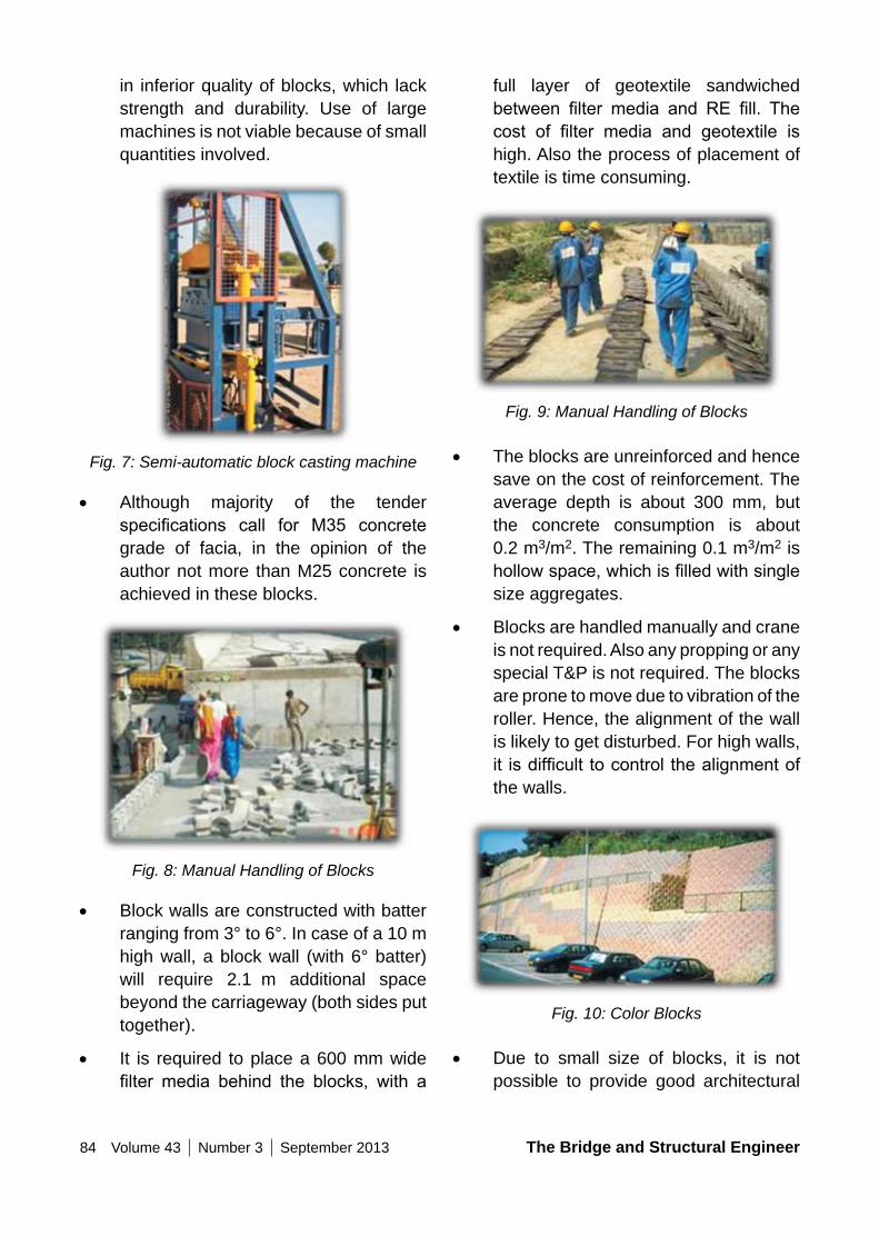
84 Volume 43 Number 3 September 2013 The Bridge and Structural Engineer
full layer of geotextile sandwiched between filter media and RE fill. Thecost of filter media and geotextile ishigh. Also the process of placement of textile is time consuming.
Fig. 9: Manual Handling of Blocks
• The blocks are unreinforced and hence save on the cost of reinforcement. The average depth is about 300 mm, but the concrete consumption is about 0.2 m3/m2. The remaining 0.1 m3/m2 is hollowspace,whichisfilledwithsinglesize aggregates.
• Blocks are handled manually and crane is not required. Also any propping or any special T&P is not required. The blocks are prone to move due to vibration of the roller. Hence, the alignment of the wall is likely to get disturbed. For high walls, it isdifficult tocontrol thealignmentofthe walls.
Fig. 10: Color Blocks
• Due to small size of blocks, it is not possible to provide good architectural
in inferior quality of blocks, which lack strength and durability. Use of large machines is not viable because of small quantities involved.
Fig. 7: Semi-automatic block casting machine
• Although majority of the tender specifications call for M35 concretegrade of facia, in the opinion of the author not more than M25 concrete is achieved in these blocks.
Fig. 8: Manual Handling of Blocks
• Block walls are constructed with batter ranging from 3° to 6°. In case of a 10 m high wall, a block wall (with 6° batter) will require 2.1 m additional space beyond the carriageway (both sides put together).
• It is required to place a 600 mm wide filter media behind the blocks, with a
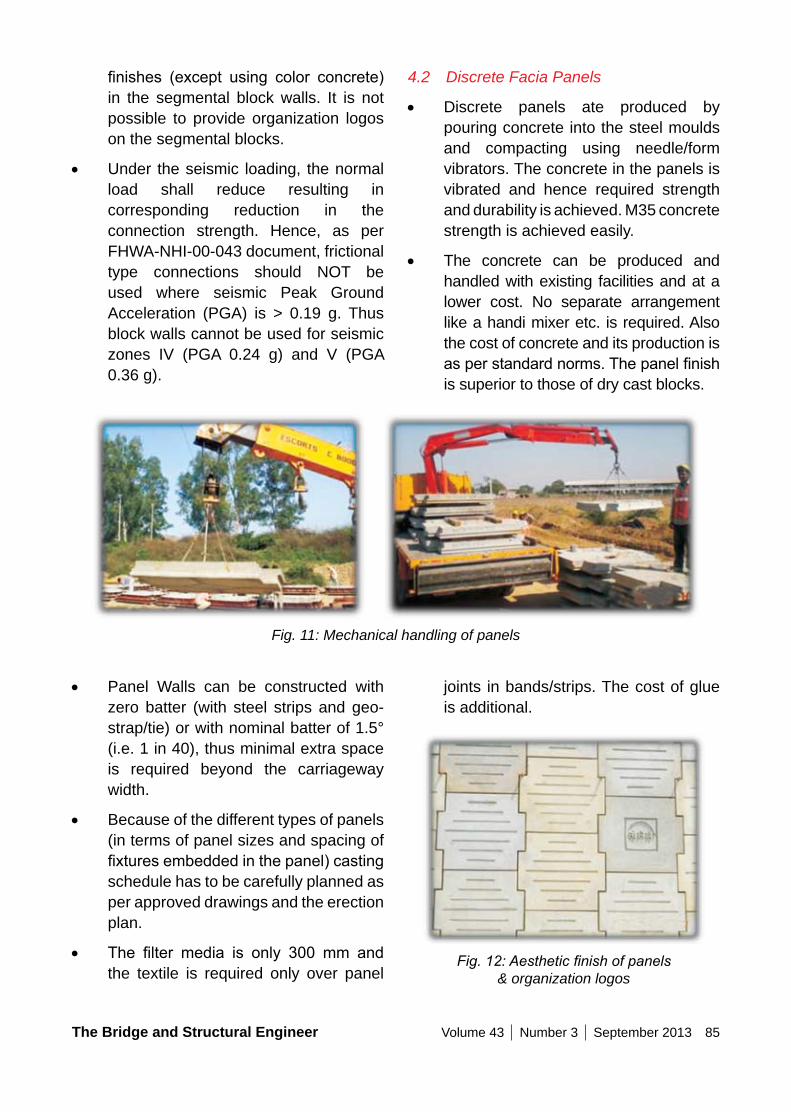
The Bridge and Structural Engineer Volume 43 Number 3 September 2013 85
4.2 Discrete Facia Panels
• Discrete panels ate produced by pouring concrete into the steel moulds and compacting using needle/form vibrators. The concrete in the panels is vibrated and hence required strength and durability is achieved. M35 concrete strength is achieved easily.
• The concrete can be produced and handled with existing facilities and at a lower cost. No separate arrangement like a handi mixer etc. is required. Also the cost of concrete and its production is asperstandardnorms.Thepanelfinishis superior to those of dry cast blocks.
finishes (except using color concrete)in the segmental block walls. It is not possible to provide organization logos on the segmental blocks.
• Under the seismic loading, the normal load shall reduce resulting in corresponding reduction in the connection strength. Hence, as per FHWA-NHI-00-043 document, frictional type connections should NOT be used where seismic Peak Ground Acceleration (PGA) is > 0.19 g. Thus block walls cannot be used for seismic zones IV (PGA 0.24 g) and V (PGA 0.36 g).
Fig. 11: Mechanical handling of panels
• Panel Walls can be constructed with zero batter (with steel strips and geo-strap/tie) or with nominal batter of 1.5° (i.e. 1 in 40), thus minimal extra space is required beyond the carriageway width.
• Because of the different types of panels (in terms of panel sizes and spacing of fixturesembeddedinthepanel)castingschedule has to be carefully planned as per approved drawings and the erection plan.
• The filter media is only 300 mm andthe textile is required only over panel
joints in bands/strips. The cost of glue is additional.
Fig. 12: Aesthetic finish of panels & organization logos
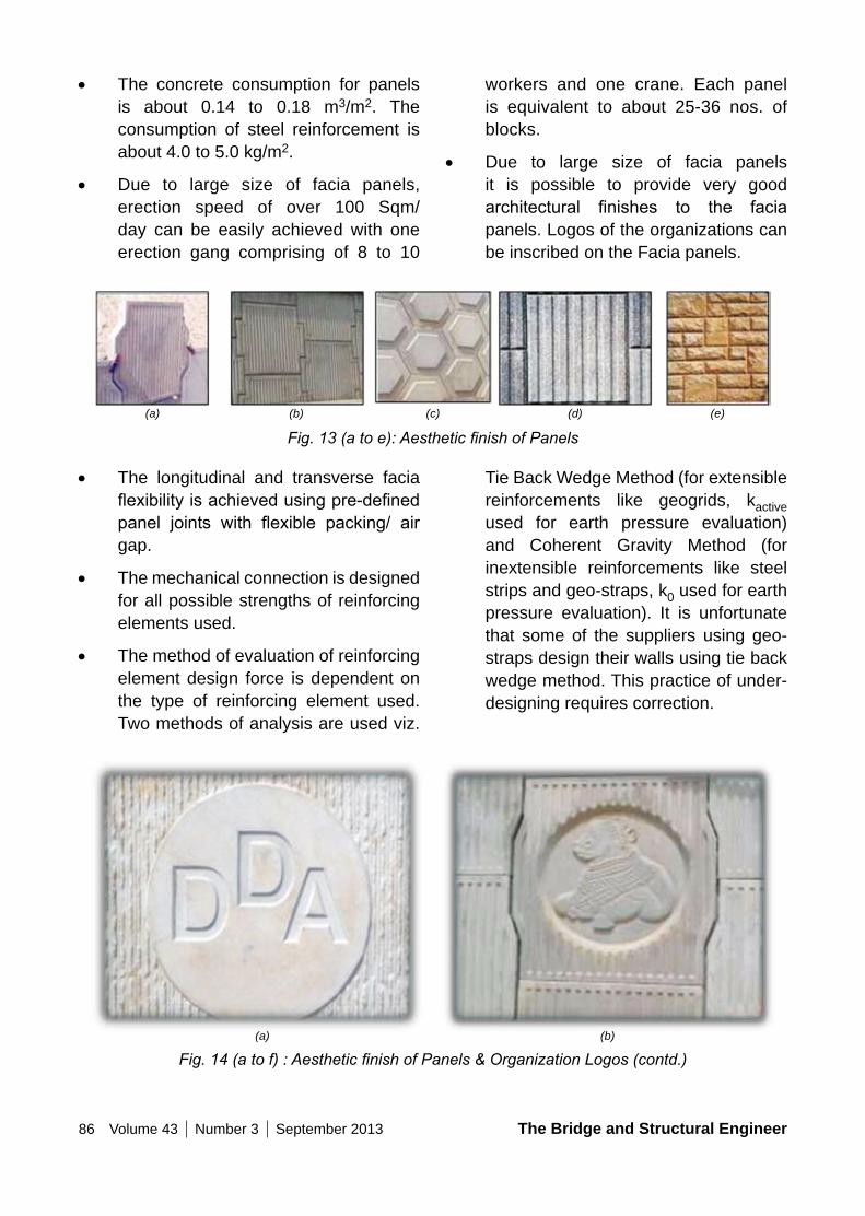
86 Volume 43 Number 3 September 2013 The Bridge and Structural Engineer
workers and one crane. Each panel is equivalent to about 25-36 nos. of blocks.
• Due to large size of facia panels it is possible to provide very good architectural finishes to the faciapanels. Logos of the organizations can be inscribed on the Facia panels.
• The concrete consumption for panels is about 0.14 to 0.18 m3/m2. The consumption of steel reinforcement is about 4.0 to 5.0 kg/m2.
• Due to large size of facia panels, erection speed of over 100 Sqm/day can be easily achieved with one erection gang comprising of 8 to 10
Fig. 13 (a to e): Aesthetic finish of Panels
• The longitudinal and transverse facia flexibilityisachievedusingpre-definedpanel joints with flexible packing/ airgap.
• The mechanical connection is designed for all possible strengths of reinforcing elements used.
• The method of evaluation of reinforcing element design force is dependent on the type of reinforcing element used. Two methods of analysis are used viz.
Tie Back Wedge Method (for extensible reinforcements like geogrids, kactive used for earth pressure evaluation) and Coherent Gravity Method (for inextensible reinforcements like steel strips and geo-straps, k0 used for earth pressure evaluation). It is unfortunate that some of the suppliers using geo-straps design their walls using tie back wedge method. This practice of under-designing requires correction.
Fig. 14 (a to f) : Aesthetic finish of Panels & Organization Logos (contd.)
(a) (b) (c) (e)(d)
(a) (b)
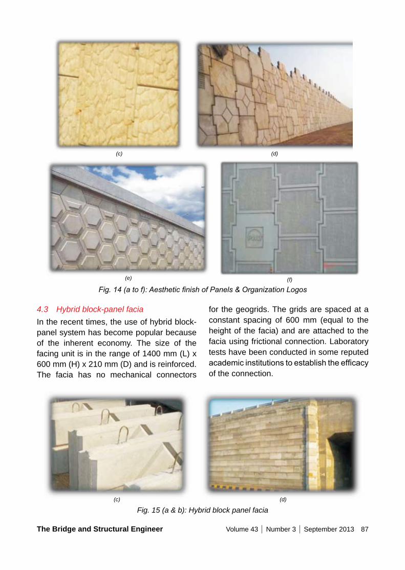
The Bridge and Structural Engineer Volume 43 Number 3 September 2013 87
Fig. 14 (a to f): Aesthetic finish of Panels & Organization Logos
4.3 Hybrid block-panel faciaIn the recent times, the use of hybrid block-panel system has become popular because of the inherent economy. The size of the facing unit is in the range of 1400 mm (L) x 600 mm (H) x 210 mm (D) and is reinforced. The facia has no mechanical connectors
for the geogrids. The grids are spaced at a constant spacing of 600 mm (equal to the height of the facia) and are attached to the facia using frictional connection. Laboratory tests have been conducted in some reputed academicinstitutionstoestablishtheefficacyof the connection.
Fig. 15 (a & b): Hybrid block panel facia
(c) (d)
(e) (f)
(c) (d)
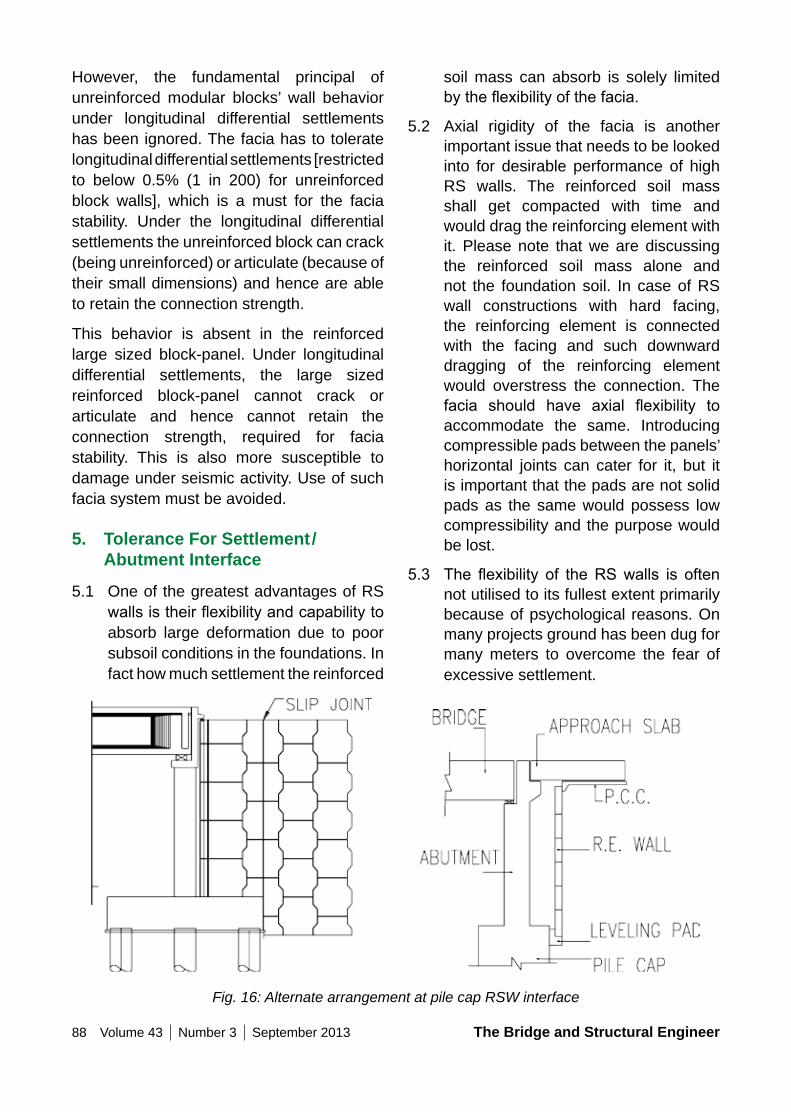
88 Volume 43 Number 3 September 2013 The Bridge and Structural Engineer
soil mass can absorb is solely limited bytheflexibilityofthefacia.
5.2 Axial rigidity of the facia is another important issue that needs to be looked into for desirable performance of high RS walls. The reinforced soil mass shall get compacted with time and would drag the reinforcing element with it. Please note that we are discussing the reinforced soil mass alone and not the foundation soil. In case of RS wall constructions with hard facing, the reinforcing element is connected with the facing and such downward dragging of the reinforcing element would overstress the connection. The facia should have axial flexibility toaccommodate the same. Introducing compressible pads between the panels’ horizontal joints can cater for it, but it is important that the pads are not solid pads as the same would possess low compressibility and the purpose would be lost.
5.3 The flexibility of theRSwalls is oftennot utilised to its fullest extent primarily because of psychological reasons. On many projects ground has been dug for many meters to overcome the fear of excessive settlement.
However, the fundamental principal of unreinforced modular blocks’ wall behavior under longitudinal differential settlements has been ignored. The facia has to tolerate longitudinal differential settlements [restricted to below 0.5% (1 in 200) for unreinforced block walls], which is a must for the facia stability. Under the longitudinal differential settlements the unreinforced block can crack (being unreinforced) or articulate (because of their small dimensions) and hence are able to retain the connection strength.
This behavior is absent in the reinforced large sized block-panel. Under longitudinal differential settlements, the large sized reinforced block-panel cannot crack or articulate and hence cannot retain the connection strength, required for facia stability. This is also more susceptible to damage under seismic activity. Use of such facia system must be avoided.
5. Tolerance For Settlement/Abutment Interface
5.1 One of the greatest advantages of RS wallsistheirflexibilityandcapabilitytoabsorb large deformation due to poor subsoil conditions in the foundations. In fact how much settlement the reinforced
Fig. 16: Alternate arrangement at pile cap RSW interface
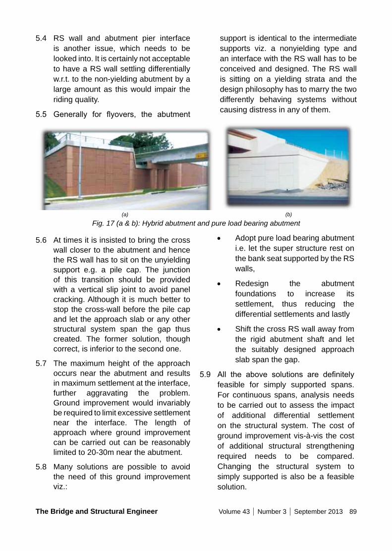
The Bridge and Structural Engineer Volume 43 Number 3 September 2013 89
support is identical to the intermediate supports viz. a nonyielding type and an interface with the RS wall has to be conceived and designed. The RS wall is sitting on a yielding strata and the design philosophy has to marry the two differently behaving systems without causing distress in any of them.
5.4 RS wall and abutment pier interface is another issue, which needs to be looked into. It is certainly not acceptable to have a RS wall settling differentially w.r.t. to the non-yielding abutment by a large amount as this would impair the riding quality.
5.5 Generally for flyovers, the abutment
Fig. 17 (a & b): Hybrid abutment and pure load bearing abutment
5.6 At times it is insisted to bring the cross wall closer to the abutment and hence the RS wall has to sit on the unyielding support e.g. a pile cap. The junction of this transition should be provided with a vertical slip joint to avoid panel cracking. Although it is much better to stop the cross-wall before the pile cap and let the approach slab or any other structural system span the gap thus created. The former solution, though correct, is inferior to the second one.
5.7 The maximum height of the approach occurs near the abutment and results in maximum settlement at the interface, further aggravating the problem. Ground improvement would invariably be required to limit excessive settlement near the interface. The length of approach where ground improvement can be carried out can be reasonably limited to 20-30m near the abutment.
5.8 Many solutions are possible to avoid the need of this ground improvement viz.:
• Adopt pure load bearing abutment i.e. let the super structure rest on the bank seat supported by the RS walls,
• Redesign the abutment foundations to increase its settlement, thus reducing the differential settlements and lastly
• Shift the cross RS wall away from the rigid abutment shaft and let the suitably designed approach slab span the gap.
5.9 All the above solutions are definitelyfeasible for simply supported spans. For continuous spans, analysis needs to be carried out to assess the impact of additional differential settlement on the structural system. The cost of ground improvement vis-à-vis the cost of additional structural strengthening required needs to be compared. Changing the structural system to simply supported is also be a feasible solution.
(a) (b)
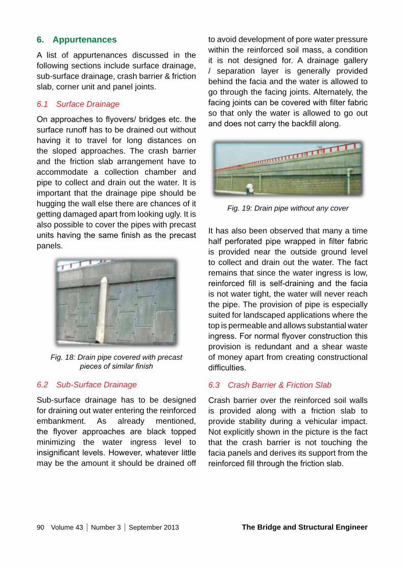
90 Volume 43 Number 3 September 2013 The Bridge and Structural Engineer
to avoid development of pore water pressure within the reinforced soil mass, a condition it is not designed for. A drainage gallery / separation layer is generally provided behind the facia and the water is allowed to go through the facing joints. Alternately, the facingjointscanbecoveredwithfilterfabricso that only the water is allowed to go out anddoesnotcarrythebackfillalong.
Fig. 19: Drain pipe without any cover
It has also been observed that many a time half perforated pipewrapped in filter fabricis provided near the outside ground level to collect and drain out the water. The fact remains that since the water ingress is low, reinforced fill is self-draining and the faciais not water tight, the water will never reach the pipe. The provision of pipe is especially suited for landscaped applications where the top is permeable and allows substantial water ingress.Fornormalflyoverconstructionthisprovision is redundant and a shear waste of money apart from creating constructional difficulties.
6.3 Crash Barrier & Friction Slab
Crash barrier over the reinforced soil walls is provided along with a friction slab to provide stability during a vehicular impact. Not explicitly shown in the picture is the fact that the crash barrier is not touching the facia panels and derives its support from the reinforcedfillthroughthefrictionslab.
6. AppurtenancesA list of appurtenances discussed in the following sections include surface drainage, sub-surface drainage, crash barrier & friction slab, corner unit and panel joints.
6.1 Surface Drainage
Onapproachestoflyovers/bridgesetc.thesurface runoff has to be drained out without having it to travel for long distances on the sloped approaches. The crash barrier and the friction slab arrangement have to accommodate a collection chamber and pipe to collect and drain out the water. It is important that the drainage pipe should be hugging the wall else there are chances of it getting damaged apart from looking ugly. It is also possible to cover the pipes with precast unitshavingthesamefinishastheprecastpanels.
Fig. 18: Drain pipe covered with precast pieces of similar finish
6.2 Sub-Surface Drainage
Sub-surface drainage has to be designed for draining out water entering the reinforced embankment. As already mentioned, the flyover approaches are black toppedminimizing the water ingress level to insignificant levels.However,whatever littlemay be the amount it should be drained off
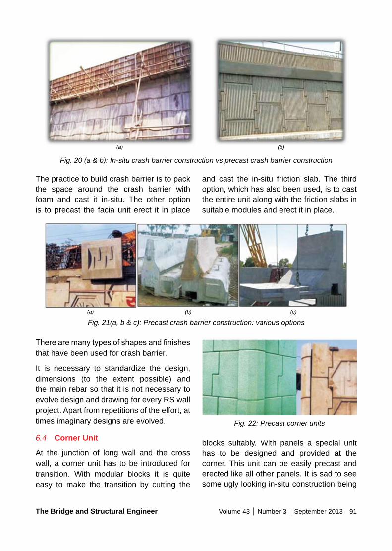
The Bridge and Structural Engineer Volume 43 Number 3 September 2013 91
and cast the in-situ friction slab. The third option, which has also been used, is to cast the entire unit along with the friction slabs in suitable modules and erect it in place.
The practice to build crash barrier is to pack the space around the crash barrier with foam and cast it in-situ. The other option is to precast the facia unit erect it in place
Fig. 20 (a & b): In-situ crash barrier construction vs precast crash barrier construction
Fig. 21(a, b & c): Precast crash barrier construction: various options
Fig. 22: Precast corner units
blocks suitably. With panels a special unit has to be designed and provided at the corner. This unit can be easily precast and erected like all other panels. It is sad to see some ugly looking in-situ construction being
Therearemanytypesofshapesandfinishesthat have been used for crash barrier.
It is necessary to standardize the design, dimensions (to the extent possible) and the main rebar so that it is not necessary to evolve design and drawing for every RS wall project. Apart from repetitions of the effort, at times imaginary designs are evolved.
6.4 Corner Unit
At the junction of long wall and the cross wall, a corner unit has to be introduced for transition. With modular blocks it is quite easy to make the transition by cutting the
(a) (b)
(a) (b) (c)
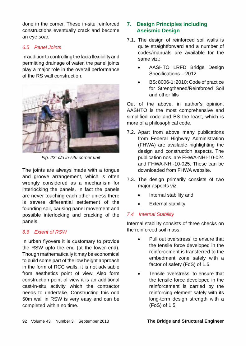
92 Volume 43 Number 3 September 2013 The Bridge and Structural Engineer
7. Design Principles including Aseismic Design
7.1. The design of reinforced soil walls is quite straightforward and a number of codes/manuals are available for the same viz.:
• AASHTO LRFD Bridge Design Specifications–2012
• BS: 8006-1: 2010: Code of practice for Strengthened/Reinforced Soil andotherfills
Out of the above, in author’s opinion, AASHTO is the most comprehensive and simplified code and BS the least, which ismore of a philosophical code.
7.2. Apart from above many publications from Federal Highway Administration (FHWA) are available highlighting the design and construction aspects. The publication nos. are FHWA-NHI-10-024 and FHWA-NHI-10-025. These can be downloaded from FHWA website.
7.3. The design primarily consists of two major aspects viz.
• Internal stability and
• External stability
7.4 Internal Stability
Internal stability consists of three checks on the reinforced soil mass:
• Pull out overstress: to ensure that the tensile force developed in the reinforcement is transferred to the embedment zone safely with a factor of safety (FoS) of 1.5.
• Tensile overstress: to ensure that the tensile force developed in the reinforcement is carried by the reinforcing element safely with its long-term design strength with a (FoS) of 1.5.
done in the corner. These in-situ reinforced constructions eventually crack and become an eye soar.
6.5 Panel Joints
Inadditiontocontrollingthefaciaflexibilityandpermitting drainage of water, the panel joints play a major role in the overall performance of the RS wall construction.
Fig. 23: c/o in-situ corner unit
The joints are always made with a tongue and groove arrangement, which is often wrongly considered as a mechanism for interlocking the panels. In fact the panels are never touching each other unless there is severe differential settlement of the founding soil, causing panel movement and possible interlocking and cracking of the panels.
6.6 Extent of RSW
Inurbanflyovers it iscustomary toprovidethe RSW upto the end (at the lower end). Though mathematically it may be economical to build some part of the low height approach in the form of RCC walls, it is not advisable from aesthetics point of view. Also form construction point of view it is an additional cast-in-situ activity which the contractor needs to undertake. Constructing this odd 50m wall in RSW is very easy and can be completed within no time.
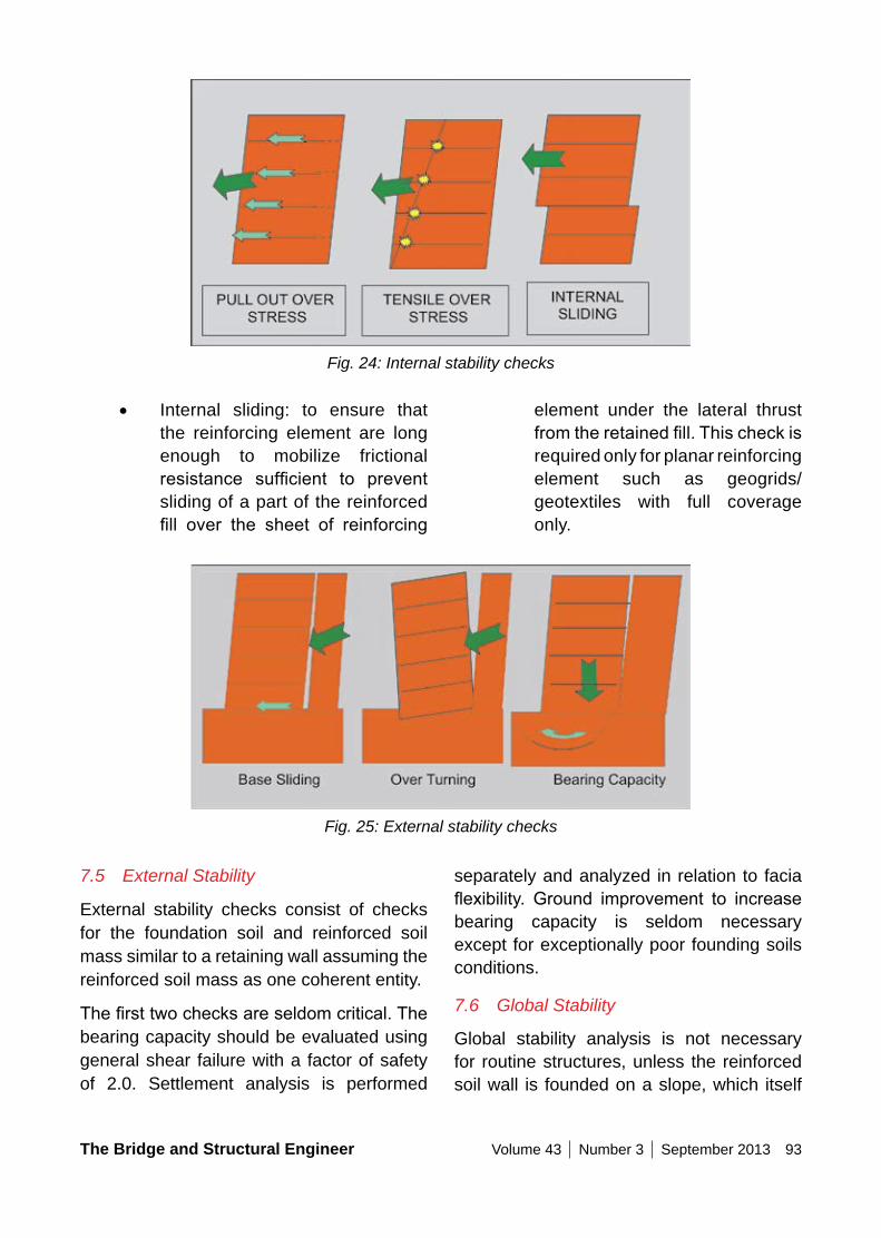
The Bridge and Structural Engineer Volume 43 Number 3 September 2013 93
element under the lateral thrust fromtheretainedfill.Thischeckisrequired only for planar reinforcing element such as geogrids/geotextiles with full coverage only.
• Internal sliding: to ensure that the reinforcing element are long enough to mobilize frictional resistance sufficient to preventsliding of a part of the reinforced fill over the sheet of reinforcing
Fig. 24: Internal stability checks
Fig. 25: External stability checks
7.5 External Stability
External stability checks consist of checks for the foundation soil and reinforced soil mass similar to a retaining wall assuming the reinforced soil mass as one coherent entity.
Thefirsttwochecksareseldomcritical.Thebearing capacity should be evaluated using general shear failure with a factor of safety of 2.0. Settlement analysis is performed
separately and analyzed in relation to facia flexibility. Ground improvement to increasebearing capacity is seldom necessary except for exceptionally poor founding soils conditions.
7.6 Global Stability
Global stability analysis is not necessary for routine structures, unless the reinforced soil wall is founded on a slope, which itself
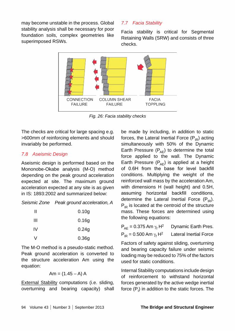
94 Volume 43 Number 3 September 2013 The Bridge and Structural Engineer
7.7 Facia Stability
Facia stability is critical for Segmental Retaining Walls (SRW) and consists of three checks.
may become unstable in the process. Global stability analysis shall be necessary for poor foundation soils, complex geometries like superimposed RSWs.
Fig. 26: Facia stability checks
The checks are critical for large spacing e.g. >600mm of reinforcing elements and should invariably be performed.
7.8 Aseismic Design
Aseismic design is performed based on the Mononobe-Okabe analysis (M-O) method depending on the peak ground acceleration expected at site. The maximum ground acceleration expected at any site is as given in IS: 1893:2002 and summarized below:
Seismic Zone Peak ground acceleration, A
II 0.10g
III 0.16g
IV 0.24g
V 0.36g
The M-O method is a pseudo-static method. Peak ground acceleration is converted to the structure acceleration Am using the equation:
Am = (1.45 – A) A
External Stability computations (i.e. sliding, overturning and bearing capacity) shall
be made by including, in addition to static forces, the Lateral Inertial Force (PIR) acting simultaneously with 50% of the Dynamic Earth Pressure (PAE) to determine the total force applied to the wall. The Dynamic Earth Pressure (PAE) is applied at a height of 0.6H from the base for level backfillconditions. Multiplying the weight of the reinforced wall mass by the acceleration Am, with dimensions H (wall height) and 0.5H, assuming horizontal backfill conditions,determine the Lateral Inertial Force (PIR). PIR is located at the centroid of the structure mass. These forces are determined using the following equations:
PAE = 0.375 Am gf H2 Dynamic Earth Pres.PIR = 0.500 Am gf H2 Lateral Inertial Force
Factors of safety against sliding, overturning and bearing capacity failure under seismic loading may be reduced to 75% of the factors used for static conditions.
Internal Stability computations include design of reinforcement to withstand horizontal forces generated by the active wedge inertial force (PI) in addition to the static forces. The
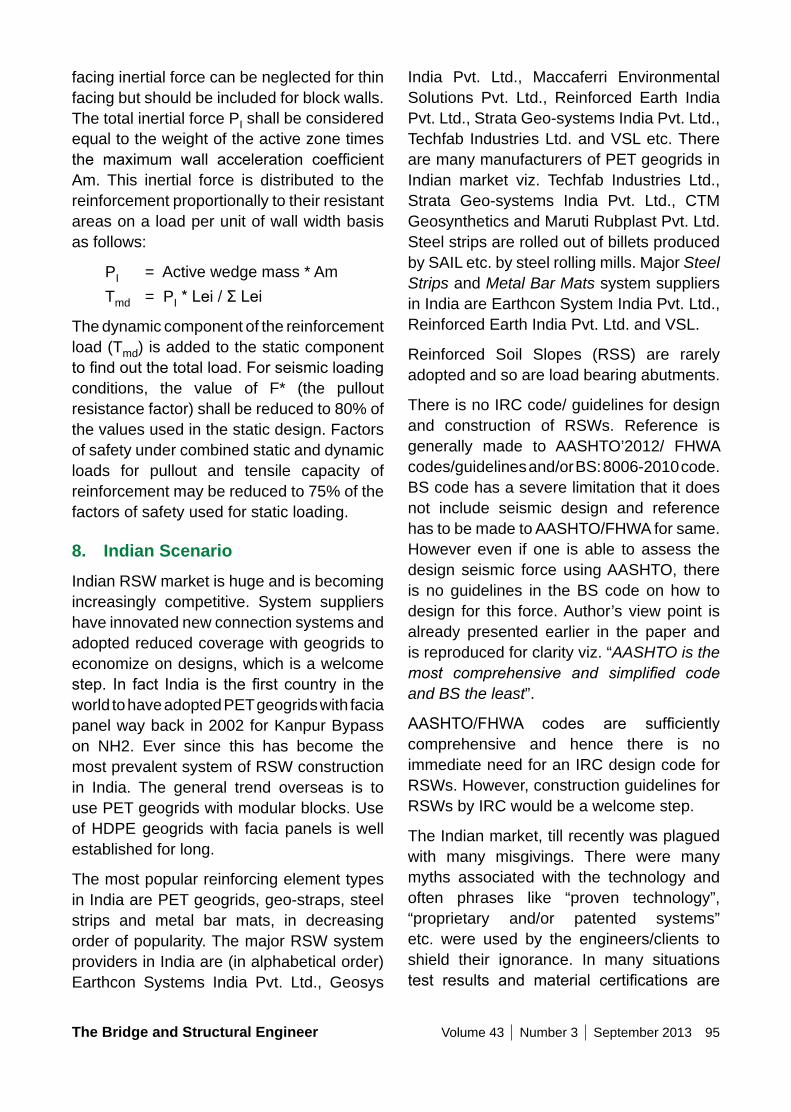
The Bridge and Structural Engineer Volume 43 Number 3 September 2013 95
India Pvt. Ltd., Maccaferri Environmental Solutions Pvt. Ltd., Reinforced Earth India Pvt. Ltd., Strata Geo-systems India Pvt. Ltd., Techfab Industries Ltd. and VSL etc. There are many manufacturers of PET geogrids in Indian market viz. Techfab Industries Ltd., Strata Geo-systems India Pvt. Ltd., CTM Geosynthetics and Maruti Rubplast Pvt. Ltd. Steel strips are rolled out of billets produced by SAIL etc. by steel rolling mills. Major Steel Strips and Metal Bar Mats system suppliers in India are Earthcon System India Pvt. Ltd., Reinforced Earth India Pvt. Ltd. and VSL.
Reinforced Soil Slopes (RSS) are rarely adopted and so are load bearing abutments.
There is no IRC code/ guidelines for design and construction of RSWs. Reference is generally made to AASHTO’2012/ FHWA codes/guidelines and/or BS: 8006-2010 code. BS code has a severe limitation that it does not include seismic design and reference has to be made to AASHTO/FHWA for same. However even if one is able to assess the design seismic force using AASHTO, there is no guidelines in the BS code on how to design for this force. Author’s view point is already presented earlier in the paper and is reproduced for clarity viz. “AASHTO is the most comprehensive and simplified code and BS the least”.
AASHTO/FHWA codes are sufficientlycomprehensive and hence there is no immediate need for an IRC design code for RSWs. However, construction guidelines for RSWs by IRC would be a welcome step.
The Indian market, till recently was plagued with many misgivings. There were many myths associated with the technology and often phrases like “proven technology”, “proprietary and/or patented systems” etc. were used by the engineers/clients to shield their ignorance. In many situations test results and material certifications are
facing inertial force can be neglected for thin facing but should be included for block walls. The total inertial force PI shall be considered equal to the weight of the active zone times the maximum wall acceleration coefficientAm. This inertial force is distributed to the reinforcement proportionally to their resistant areas on a load per unit of wall width basis as follows:
PI = Active wedge mass * AmTmd = PI*Lei/ΣLei
The dynamic component of the reinforcement load (Tmd) is added to the static component tofindoutthetotalload.Forseismicloadingconditions, the value of F* (the pullout resistance factor) shall be reduced to 80% of the values used in the static design. Factors of safety under combined static and dynamic loads for pullout and tensile capacity of reinforcement may be reduced to 75% of the factors of safety used for static loading.
8. Indian ScenarioIndian RSW market is huge and is becoming increasingly competitive. System suppliers have innovated new connection systems and adopted reduced coverage with geogrids to economize on designs, which is a welcome step. In fact India is thefirstcountry in theworld to have adopted PET geogrids with facia panel way back in 2002 for Kanpur Bypass on NH2. Ever since this has become the most prevalent system of RSW construction in India. The general trend overseas is to use PET geogrids with modular blocks. Use of HDPE geogrids with facia panels is well established for long.
The most popular reinforcing element types in India are PET geogrids, geo-straps, steel strips and metal bar mats, in decreasing order of popularity. The major RSW system providers in India are (in alphabetical order) Earthcon Systems India Pvt. Ltd., Geosys
96 Volume 43 Number 3 September 2013 The Bridge and Structural Engineer
Reinforced Soil Slopes – Volume I”, US DoT, Federal Highway Administration, November 2009, Ryan R. Berg, P.E.; Barry R. Christopher, Ph.D., P.E. and Naresh C. Samtani, Ph.D., P.E.
2. Publication no. FHWA-NHI-10-025, “Design and Construction of Mechanically Stabilized Earth Walls and Reinforced Soil Slopes – Volume II”, US DoT, Federal Highway Administration, November 2009, Ryan R. Berg, P.E.; Barry R. Christopher, Ph.D., P.E. and Naresh C. Samtani, Ph.D., P.E.
3. AASHTO LRFD Bridge Design Specifications–2012
4. BS: 8006-1: 2010: Code of Practice for Strengthened/Reinforced Soil and other fills
5. “Seismic Design and Performance of RS Retaining Structures”, Nov’19-21, 2001, Taipei, Taiwan ROC, International Geo-synthetics Engineering Forum
6. Paper No.520 “Mechanically Stabilized Earth (MSE) Walls & Reinforced Soil Slopes (RSS) Indian Scenario: A Comprehensive Review”, IRC Journal, Rajiv Goel
ignoredandSystemCertificationsfromBBA/HITEC etc. are insisted upon. This thought has to change. What is pertinent is the use of certified materials and standard designprocedures, which are well documented. A stringent quality control during material procurement and construction stage would bring better results, rather than a System Certifications from BBA/ HITEC etc. whichare often carried out with nonrepresentative material samples and recommendations are floutedbysystemsuppliersthemselves.
9. ConclusionsRSW is a flexible construction and itsfull potential need be utilised. Structural engineers need to appreciate this fact. Abutment –RSW interface need special attention and some thoughts have been shared in the paper. International codes like AASHTO and/or BS are often used for design and the need for an IRC design code is not felt by the fraternity. However, construction guidelines for RSWs by IRC would be a welcome step.
10. References1. Publication no. FHWA-NHI-10-
024, “Design and Construction of Mechanically Stabilized Earth Walls and
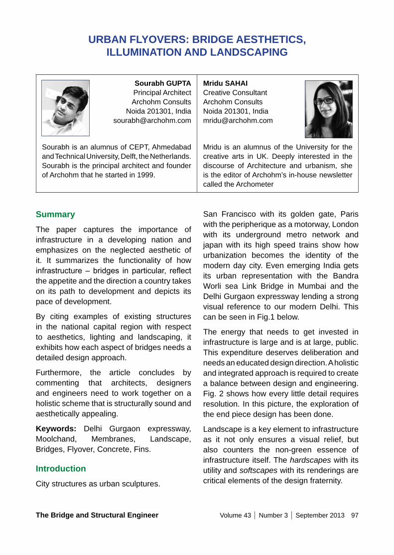
The Bridge and Structural Engineer Volume 43 Number 3 September 2013 97
URBAn FLyoVERS: BRIDGE AESTHETICS, ILLUMInATIon AnD LAnDSCAPInG
Sourabh GUPTA Principal Architect Archohm Consults
Noida 201301, India [email protected]
Sourabh is an alumnus of CEPT, Ahmedabad and Technical University, Delft, the Netherlands. Sourabh is the principal architect and founder of Archohm that he started in 1999.
Mridu SAHAI Creative Consultant Archohm Consults Noida 201301, India [email protected]
Mridu is an alumnus of the University for the creative arts in UK. Deeply interested in the discourse of Architecture and urbanism, she is the editor of Archohm’s in-house newsletter called the Archometer
SummaryThe paper captures the importance of infrastructure in a developing nation and emphasizes on the neglected aesthetic of it. It summarizes the functionality of how infrastructure–bridges inparticular, reflectthe appetite and the direction a country takes on its path to development and depicts its pace of development.
By citing examples of existing structures in the national capital region with respect to aesthetics, lighting and landscaping, it exhibits how each aspect of bridges needs a detailed design approach.
Furthermore, the article concludes by commenting that architects, designers and engineers need to work together on a holistic scheme that is structurally sound and aesthetically appealing.
Keywords: Delhi Gurgaon expressway, Moolchand, Membranes, Landscape, Bridges, Flyover, Concrete, Fins.
IntroductionCity structures as urban sculptures.
San Francisco with its golden gate, Paris with the peripherique as a motorway, London with its underground metro network and japan with its high speed trains show how urbanization becomes the identity of the modern day city. Even emerging India gets its urban representation with the Bandra Worli sea Link Bridge in Mumbai and the Delhi Gurgaon expressway lending a strong visual reference to our modern Delhi. This can be seen in Fig.1 below.
The energy that needs to get invested in infrastructure is large and is at large, public. This expenditure deserves deliberation and needs an educated design direction. A holistic and integrated approach is required to create a balance between design and engineering. Fig. 2 shows how every little detail requires resolution. In this picture, the exploration of the end piece design has been done.
Landscape is a key element to infrastructure as it not only ensures a visual relief, but also counters the non-green essence of infrastructure itself. The hardscapes with its utility and softscapes with its renderings are critical elements of the design fraternity.
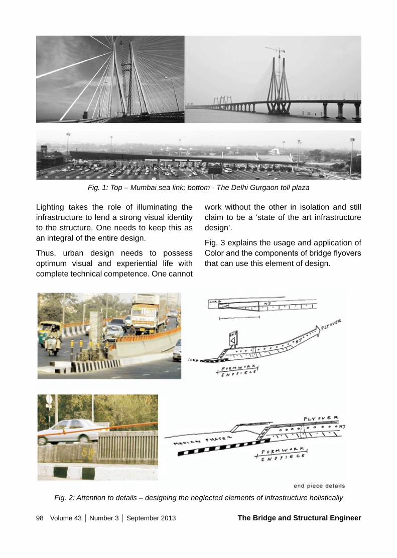
98 Volume 43 Number 3 September 2013 The Bridge and Structural Engineer
work without the other in isolation and still claim to be a ‘state of the art infrastructure design’.
Fig. 3 explains the usage and application of Colorandthecomponentsofbridgeflyoversthat can use this element of design.
Lighting takes the role of illuminating the infrastructure to lend a strong visual identity to the structure. One needs to keep this as an integral of the entire design.
Thus, urban design needs to possess optimum visual and experiential life with complete technical competence. One cannot
Fig. 1: Top – Mumbai sea link; bottom - The Delhi Gurgaon toll plaza
Fig. 2: Attention to details – designing the neglected elements of infrastructure holistically
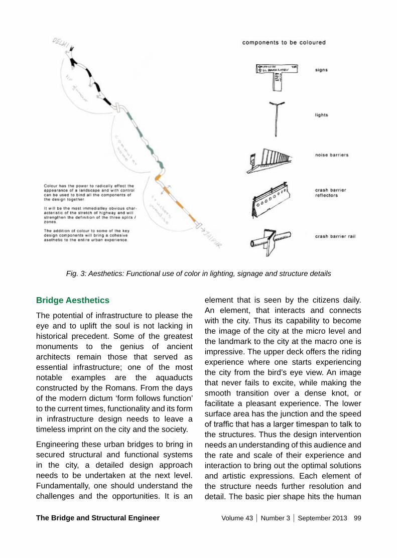
The Bridge and Structural Engineer Volume 43 Number 3 September 2013 99
Fig. 3: Aesthetics: Functional use of color in lighting, signage and structure details
element that is seen by the citizens daily. An element, that interacts and connects with the city. Thus its capability to become the image of the city at the micro level and the landmark to the city at the macro one is impressive. The upper deck offers the riding experience where one starts experiencing the city from the bird’s eye view. An image that never fails to excite, while making the smooth transition over a dense knot, or facilitate a pleasant experience. The lower surface area has the junction and the speed oftrafficthathasalargertimespantotalktothe structures. Thus the design intervention needs an understanding of this audience and the rate and scale of their experience and interaction to bring out the optimal solutions and artistic expressions. Each element of the structure needs further resolution and detail. The basic pier shape hits the human
Bridge AestheticsThe potential of infrastructure to please the eye and to uplift the soul is not lacking in historical precedent. Some of the greatest monuments to the genius of ancient architects remain those that served as essential infrastructure; one of the most notable examples are the aquaducts constructed by the Romans. From the days of the modern dictum ‘form follows function’ to the current times, functionality and its form in infrastructure design needs to leave a timeless imprint on the city and the society.
Engineering these urban bridges to bring in secured structural and functional systems in the city, a detailed design approach needs to be undertaken at the next level. Fundamentally, one should understand the challenges and the opportunities. It is an
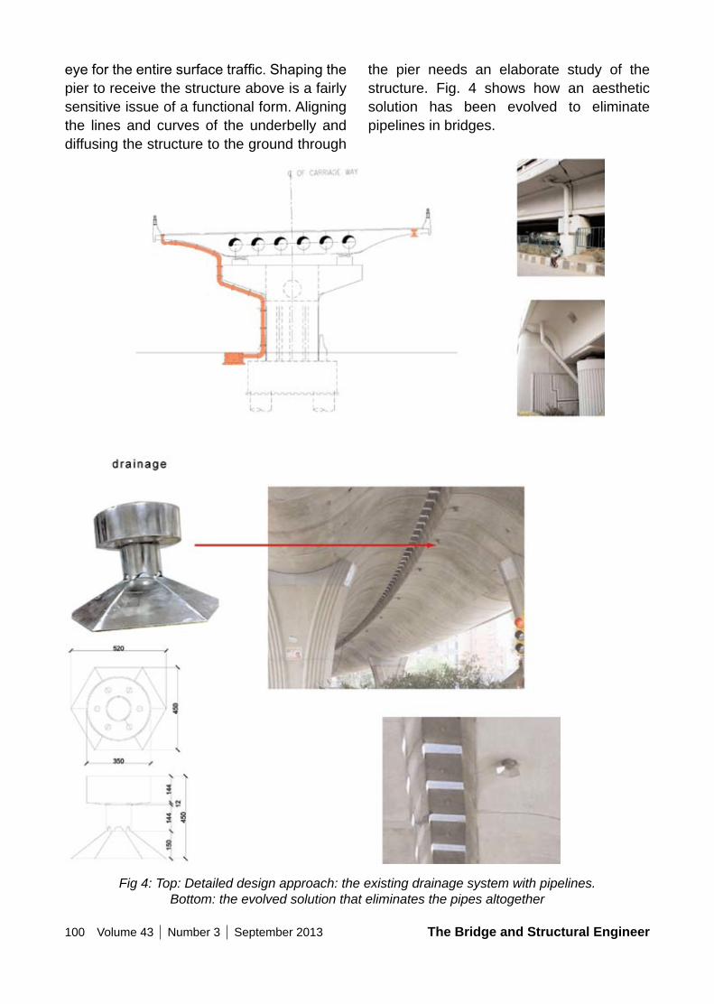
100 Volume 43 Number 3 September 2013 The Bridge and Structural Engineer
the pier needs an elaborate study of the structure. Fig. 4 shows how an aesthetic solution has been evolved to eliminate pipelines in bridges.
eyefortheentiresurfacetraffic.Shapingthepier to receive the structure above is a fairly sensitive issue of a functional form. Aligning the lines and curves of the underbelly and diffusing the structure to the ground through
Fig 4: Top: Detailed design approach: the existing drainage system with pipelines. Bottom: the evolved solution that eliminates the pipes altogether
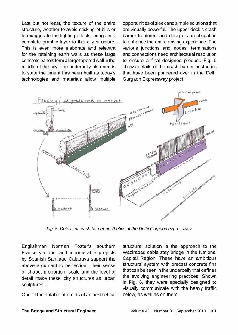
The Bridge and Structural Engineer Volume 43 Number 3 September 2013 101
opportunities of sleek and simple solutions that are visually powerful. The upper deck‘s crash barrier treatment and design is an obligation to enhance the entire driving experience. The various junctions and nodes, terminations and connections need architectural resolution to ensure a final designed product. Fig. 5shows details of the crash barrier aesthetics that have been pondered over in the Delhi Gurgaon Expressway project.
Last but not least, the texture of the entire structure, weather to avoid sticking of bills or to exaggerate the lighting effects, brings in a complete graphic layer to this city structure. This is even more elaborate and relevant for the retaining earth walls as these large concrete panels form a large tapered wall in the middle of the city. The underbelly also needs to state the time it has been built as today’s technologies and materials allow multiple
Fig. 5: Details of crash barrier aesthetics of the Delhi Gurgaon expressway
Englishman Norman Foster’s southern France via duct and innumerable projects by Spanish Santiago Calatrava support the above argument to perfection. Their sense of shape, proportion, scale and the level of detail make these ‘city structures as urban sculptures’.
One of the notable attempts of an aesthetical
structural solution is the approach to the Wazirabad cable stay bridge in the National Capital Region. These have an ambitious structuralsystemwithprecastconcretefinsthatcanbeseenintheunderbellythatdefinesthe evolving engineering practices. Shown in Fig. 6, they were specially designed to visually communicatewith theheavy trafficbelow, as well as on them.
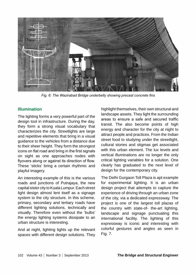
102 Volume 43 Number 3 September 2013 The Bridge and Structural Engineer
highlight themselves, their own structural and landscape assets. They light the surrounding areas to ensure a safe and secured traffictransit. The also become points of high energy and character for the city at night to attract people and practices. From the Indian street food to studying under the streetlight, cultural stories and stigmas get associated with this urban element. The lux levels and vertical illuminations are no longer the only critical lighting variables for a solution. One clearly has graduated to the next level of design for the contemporary city.
The Delhi Gurgaon Toll Plaza is apt example for experimental lighting. It is an urban design project that attempts to capture the experience of driving through an urban zone of the city, via a dedicated expressway. The project is one of the largest toll plazas of the country with state-of- the-art lighting, landscape and signage punctuating this international facility. The lighting of this expressway is iconic and interesting with colorful gestures and angles as seen in Fig. 7.
IlluminationThe lighting forms a very powerful part of the design tool in infrastructure. During the day, they form a strong visual vocabulary that characterizes the city. Streetlights are large and repetitive elements that bring in a visual guidance to the vehicles from a distance due to their sheer height. They form the strongest iconsonflatroadandbringinthefirstsignalson sight as one approaches nodes with flyoversalongoragainstitsdirectionofflow.These ‘sticks’ bring a certain rhythmic and playful imagery.
An interesting example of this is the various roads and junctions of Putrajaya, the new capital sister city to Kuala Lumpur. Each street light design almost lent itself as a signage system to the city structure. In this scheme, primary, secondary and tertiary roads have different lighting solutions, technically and visually. Therefore even without the ‘bulbs’ the energy lighting systems dissipate to an urban structure is interesting.
And at night, lighting lights up the relevant spaces with different design solutions. They
Fig. 6: The Wazirabad Bridge underbelly showing precast concrete fins
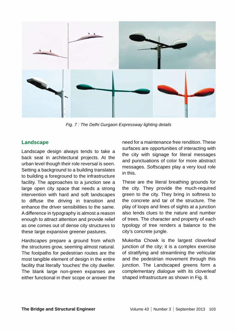
The Bridge and Structural Engineer Volume 43 Number 3 September 2013 103
Fig. 7 : The Delhi Gurgaon Expressway lighting details
LandscapeLandscape design always tends to take a back seat in architectural projects. At the urban level though their role reversal is seen. Setting a background to a building translates to building a foreground to the infrastructure facility. The approaches to a junction see a large open city space that needs a strong intervention with hard and soft landscapes to diffuse the driving in transition and enhance the driver sensibilities to the same. A difference in typography is almost a reason enough to attract attention and provide relief as one comes out of dense city structures to these large expansive greener pastures.
Hardscapes prepare a ground from which the structures grow, seeming almost natural. The footpaths for pedestrian routes are the most tangible element of design in the entire facility that literally ‘touches’ the city dweller. The blank large non-green expanses are either functional in their scope or answer the
need for a maintenance free rendition. These surfaces are opportunities of interacting with the city with signage for literal messages and punctuations of color for more abstract messages. Softscapes play a very loud role in this.
These are the literal breathing grounds for the city. They provide the much-required green to the city. They bring in softness to the concrete and tar of the structure. The play of loops and lines of sights at a junction also lends clues to the nature and number of trees. The character and property of each typology of tree renders a balance to the city’s concrete jungle.
Mukerba Chowk is the largest cloverleaf junction of the city; it is a complex exercise of stratifying and streamlining the vehicular and the pedestrian movement through this junction. The Landscaped greens form a complementary dialogue with its cloverleaf shaped infrastructure as shown in Fig. 8.

104 Volume 43 Number 3 September 2013 The Bridge and Structural Engineer
to organize the junction was evolved. The suspended bridge and fins as well as thecaterpillar like structures over the underpass lend a new identity to this famous junction seen in Fig. 9.
other notable Structures
The Moolchand underpass is an urban gesturethatinfluenceslargepedestrianandvehiculartraffic.Aconceptofacirculartube
Fig. 8 : The Mukerba Chowk Greens
Fig. 9: Moolchand caterpillar structures
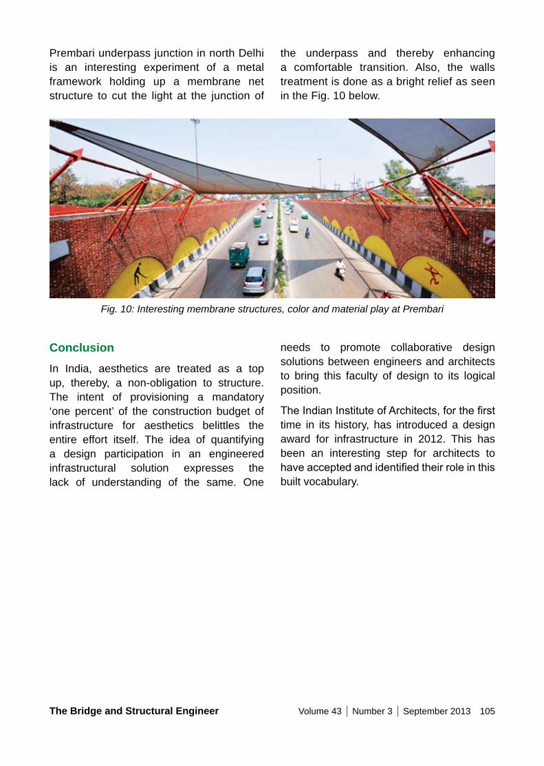
The Bridge and Structural Engineer Volume 43 Number 3 September 2013 105
Prembari underpass junction in north Delhi is an interesting experiment of a metal framework holding up a membrane net structure to cut the light at the junction of
the underpass and thereby enhancing a comfortable transition. Also, the walls treatment is done as a bright relief as seen in the Fig. 10 below.
Fig. 10: Interesting membrane structures, color and material play at Prembari
ConclusionIn India, aesthetics are treated as a top up, thereby, a non-obligation to structure. The intent of provisioning a mandatory ‘one percent’ of the construction budget of infrastructure for aesthetics belittles the entire effort itself. The idea of quantifying a design participation in an engineered infrastructural solution expresses the lack of understanding of the same. One
needs to promote collaborative design solutions between engineers and architects to bring this faculty of design to its logical position.
TheIndianInstituteofArchitects,forthefirsttime in its history, has introduced a design award for infrastructure in 2012. This has been an interesting step for architects to haveacceptedandidentifiedtheirroleinthisbuilt vocabulary.
106 Volume 43 Number 3 September 2013 The Bridge and Structural Engineer
A PERSPECTIVE on MAInTEnAnCE nEEDS oF URBAn FLyoVERS
Dr Lakshmy PARAMESWARAn Chief Scientist, Bridges & Structures Division CSIR-Central Road Research Institute New Delhi-110025 [email protected]
Summary
With huge investments being made in the development of road transportation network inurbanarea,maintenanceofflyovers isavery important activity to achieve a design life of about 100 years. Maintenance becomes challenging due to the use of variety of materials, different structural configurationand erection techniques being adopted for constructionofaflyover located inahighlycongested urban area. In this paper an attempt has been made to discuss about the maintenancemanagementofflyovers,whichessentially start after the construction, during the design life of the structure. It essentially includes inventorisation, inspection, distressdiagnostics, prioritizationof flyoverfor maintenance, selection of repair and strengthening techniques depending upon the construction material, budgeting, and implementation of maintenance schemes including quality control. Also, other related concerns such as fire and seismic hazard,vibration and need for adoption of accelerated techniques for maintenance have been addressed.
Keywords: Flyover; reinforced cement concrete; precast segmental; steel-concrete composite; bearings; expansion joints; maintenance management; inventorization;
distress diagnostics; repair; strengthening; quality control
1. IntroductionRapid industrialization in India demands an efficient road transportation infrastructure,which has led to construction of network of roads with inbuilt bridges and flyovers.Recently, huge investments have been made to meet the increasing travel demand of users. Large number of flyovers isbeing constructed in various major cities as they help in easing traffic congestionand reducing the travel time of road users. Construction of large number of flyovergained momentum in Delhi around 1980’s before the ASIAD and again drastically increased before the Common Wealth Games held in 2010. Also, large number of flyoverswasconstructedinMumbaiduring1997-2002. At present, Kolkata has more thansixtyflyoversandmanymoreareunderconstruction and similar situation exist in Chennai and Bangalore. The length of the flyovers also varies between few hundredmetres to several kilometres, for example, therecentlyconstructedflyoverinPanipatisabout3.6kmlongandthelongestflyoverinIndia is in Hyderabad with a length of about 11.6km. Over the years drastic changes have taken place in the technology used for
Lakshmy Parameswaran, born in 1962, received PhD (Civil Engineering) from IIT Roorkee. She has more than 26 years experience and is currently working in CSIR-CRRI as a Chief Scientist. Her main areas of research are bridge management, health monitoring of bridges and bridge aerodynamics.
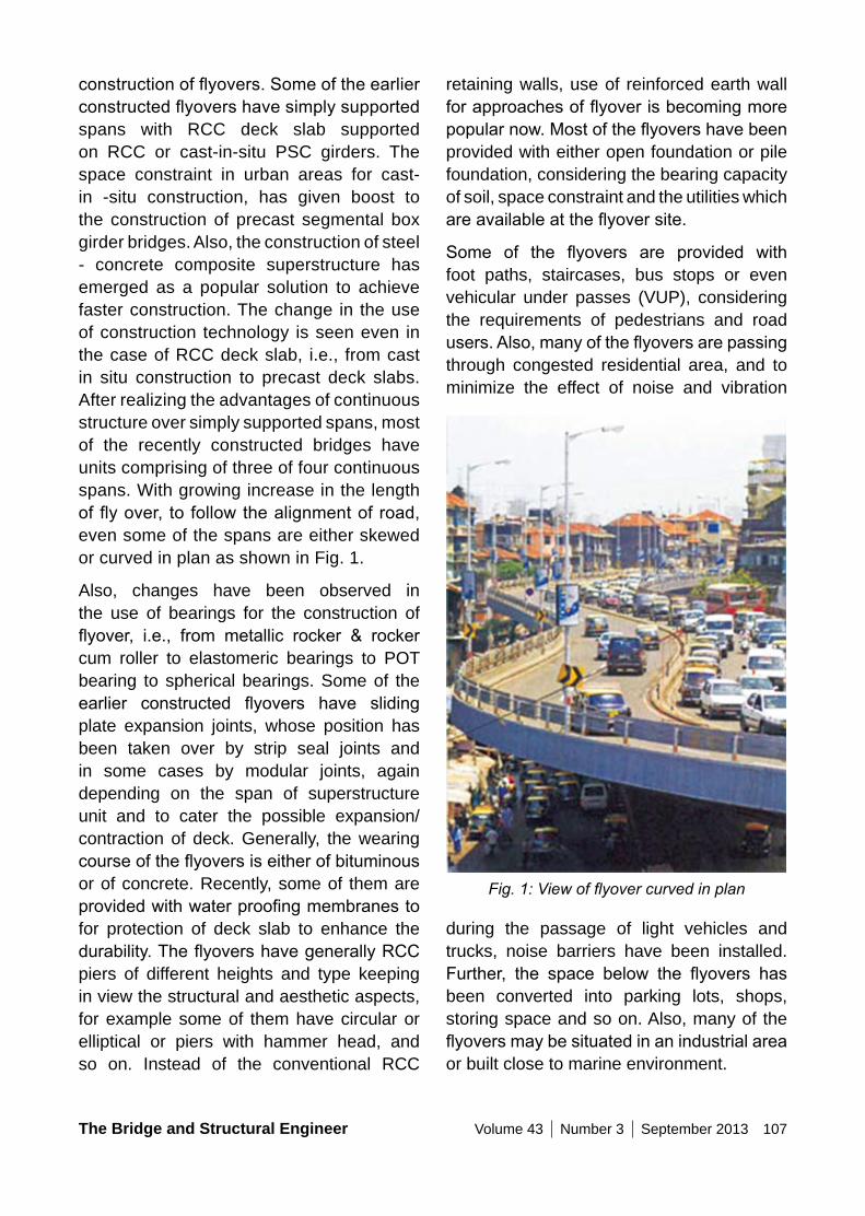
The Bridge and Structural Engineer Volume 43 Number 3 September 2013 107
retaining walls, use of reinforced earth wall forapproachesofflyoverisbecomingmorepopularnow.Mostoftheflyovershavebeenprovided with either open foundation or pile foundation, considering the bearing capacity of soil, space constraint and the utilities which areavailableattheflyoversite.
Some of the flyovers are provided withfoot paths, staircases, bus stops or even vehicular under passes (VUP), considering the requirements of pedestrians and road users.Also,manyoftheflyoversarepassingthrough congested residential area, and to minimize the effect of noise and vibration
Fig. 1: View of flyover curved in plan
during the passage of light vehicles and trucks, noise barriers have been installed. Further, the space below the flyovers hasbeen converted into parking lots, shops, storing space and so on. Also, many of the flyoversmaybesituatedinanindustrialareaor built close to marine environment.
constructionofflyovers.Someoftheearlierconstructedflyovershavesimplysupportedspans with RCC deck slab supported on RCC or cast-in-situ PSC girders. The space constraint in urban areas for cast-in -situ construction, has given boost to the construction of precast segmental box girder bridges. Also, the construction of steel - concrete composite superstructure has emerged as a popular solution to achieve faster construction. The change in the use of construction technology is seen even in the case of RCC deck slab, i.e., from cast in situ construction to precast deck slabs. After realizing the advantages of continuous structure over simply supported spans, most of the recently constructed bridges have units comprising of three of four continuous spans. With growing increase in the length offlyover, tofollowthealignmentofroad,even some of the spans are either skewed or curved in plan as shown in Fig. 1.
Also, changes have been observed in the use of bearings for the construction of flyover, i.e., from metallic rocker & rockercum roller to elastomeric bearings to POT bearing to spherical bearings. Some of the earlier constructed flyovers have slidingplate expansion joints, whose position has been taken over by strip seal joints and in some cases by modular joints, again depending on the span of superstructure unit and to cater the possible expansion/ contraction of deck. Generally, the wearing courseoftheflyoversiseitherofbituminousor of concrete. Recently, some of them are providedwithwaterproofingmembranestofor protection of deck slab to enhance the durability.TheflyovershavegenerallyRCCpiers of different heights and type keeping in view the structural and aesthetic aspects, for example some of them have circular or elliptical or piers with hammer head, and so on. Instead of the conventional RCC
108 Volume 43 Number 3 September 2013 The Bridge and Structural Engineer
at a minimum life cycle cost. Therefore, it involves all activities at requisite time interval, needed to preserve the intended load carrying capacity of the structure without compromising the safety of road users. The maintenance operations begin with the opening of the bridge to traffic. Itincludes preventive maintenance, routine repair strengthening and special repairs to be undertaken to rectify any damage caused by hazards like earthquake, cyclones, fire,etc.
2.1 Inventorization of Flyover
Theprimeneedforanyflyovermaintenancemanagement is a complete accurate and up-to-date record of the bridge. The purpose of inspection and field studies is not fullyachieved without the maintenance of proper records. The records should thus provide a complete up-to-date history of the structure right from the construction stage including all repair and rehabilitation undertaken so far.
The inventorizarion consists of collection of administrative record, geometric record, technical data, structural design record, geotechnical record, structural drawings and photographs and create a database. If the flyover crossesa railway lineor hasavehicular underpass (VUP), then there is a need to collect the data related to ROB and VUP. The inventory will be used for planning the visual inspection, load carrying capacity evaluation and deciding the maintenance strategies depending upon the material used forconstructionofvariouselementsflyover.Also, it is advisable to develop the inventory in a GIS platform so as to derive maximum benefitsinmacro-levelassetmanagement.Also this will enable the owners of structure to allocate the maintenance funds area, road or structure wise. Also, the creation of road network with location of structures
Lack of regular maintenance of flyover inIndia has led to deterioration of some of them rather early in their life. Maintenance of these generally gets neglected because of the prevailing misconception that the bridges and flyovers once constructed donot need, any substantial maintenance particularlyinthefirstfewdecadessoonafterthe construction. In the absence of proper database and regular inspection, generally ad-hoc decisions are taken regarding maintenance as a sort of crisis management without considering the magnitude of the overall problem or intense priorities at road network level. This results in in-effective utilization of maintenance funds. Again, with more number of flyover deteriorationbeing reported, coupled with increased use, additional resources will have to be provided for maintaining these structures during the design life. This emphasizes the need for optimal utilization of available resources.
Based on the experience gained during the development of Bridge Maintenance Management System, an attempt has been made in this paper to discuss about the maintenance management of flyovers,which essentially start after the construction during the design life of the structure. It essentially includes inventorization, inspection, distress diagnostics, prioritization offlyoverformaintenance,selectionofrepairand strengthening techniques depending upon the construction material budgeting, implementation of maintenance schemes including quality control.
2. Maintenance ManagementMaintenanceofflyoversisaveryimportantissue, keeping in view the complexities involved in the construction, service life of flyover and various other aspects. Also,it ensures that the structure remains fitfor the intended purpose over design life
The Bridge and Structural Engineer Volume 43 Number 3 September 2013 109
pier, abutment and foundation.
The load carrying capacity of the steel – concrete composite bridge is generally affected due to natural aging and increasing load spectra and deterioration by corrosion. One significant cause of deterioration ofsteel-concrete composite bridge structure is corrosion. Problems are often seen on steel surfaces under leaking expansion joints, bottom flange of girders due tobuilt-up moisture trapped debris, lapped joints, connections, welds with composition different from base metal can promote corrosion and high tensile stress can accelerate corrosion. Also, the capacity loss of steel girder is dependent on rate of corrosion. The mechanical flaw andmicro cracks in stress concentrated tensile regions of a component can even lead to brittle failure. Therefore, apart from cracking and corrosion, these bridges are to be checked for impact damage, misalignment, buckling of webs, loss of camber and unusual vibration. Further, steel –concrete composite bridges are provided with shear connectors, whose strength is often reduced under fatigue loads.
Inmany of the existing flyovers, it is oftenseen that damages associated with bearings and expansion joints have cropped up just after 10-15 years of construction. Some of the problems in expansion joints and bearings are mainly due to improper installation and lack of routine inspection and maintenance. As the life of these elements is much less than the design life of bridge, during the service life, these elements are to be repaired or replaced number of times. More details on condition assessment of bearings, expansion joints and their replacement has been discussed by Sharma et al (2013).
marked helps to identify the possible detour routes during the execution of major repair or rehabilitation work.
2.2 Inspection and distress diagnostics
Theinspectionofaflyoverhelpstoidentifythe type, location, extent and probable cause of distresses in various elements of a flyover.Thecausesofdistressesinflyoverarea aging of the structure, increased traffic loading and volume, passage ofoversized and overweight vehicles, design and construction deficiencies, vibration,effect of seasonal weather, exposure to aggressive Environment, natural calamities such as earthquake, cyclone etc, manmade calamities such as fire, theft of flyoverelements and vandalism.
The deterioration of RC elements can be due four processes- (i) chemical (ii) physical (iii) mechanical and (iv) electro-chemical. The associated effects are seen during the visual inspection. For example, leaching, sulphate attack and alkali-silica reaction falls under chemical process. Some of the effects seen are efflorescence, cracks,disintegration of concrete, map cracking and so on. The physical process includes repeated expansion and contraction of deck, which can result in distress like cracking. Abrasion caused by moving vehicles is a mechanical action, which causes wear and tear of deck surface. Corrosion of steel in concrete is an electro-chemical process andisidentifiedwithruststain,crackalongthe reinforcement, delaminations and spalling during visual inspection. Some of these distresses are shown in Fig. 2 to 5. Also, many of deteriorating mechanism like corrosion, sulphate attack and ASR can affect the load carrying capacity of primary structural elements like deck slab, girders,
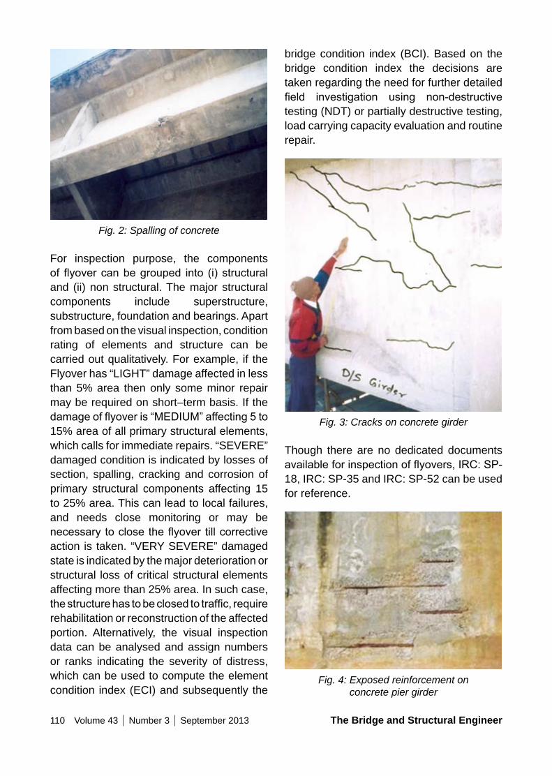
110 Volume 43 Number 3 September 2013 The Bridge and Structural Engineer
bridge condition index (BCI). Based on the bridge condition index the decisions are taken regarding the need for further detailed field investigation using non-destructivetesting (NDT) or partially destructive testing, load carrying capacity evaluation and routine repair.
Fig. 3: Cracks on concrete girder
Though there are no dedicated documents availableforinspectionofflyovers,IRC:SP-18, IRC: SP-35 and IRC: SP-52 can be used for reference.
Fig. 4: Exposed reinforcement on concrete pier girder
Fig. 2: Spalling of concrete
For inspection purpose, the components offlyovercanbegrouped into (i)structuraland (ii) non structural. The major structural components include superstructure, substructure, foundation and bearings. Apart from based on the visual inspection, condition rating of elements and structure can be carried out qualitatively. For example, if the Flyover has “LIGHT” damage affected in less than 5% area then only some minor repair may be required on short–term basis. If the damageofflyoveris“MEDIUM”affecting5to15% area of all primary structural elements, which calls for immediate repairs. “SEVERE” damaged condition is indicated by losses of section, spalling, cracking and corrosion of primary structural components affecting 15 to 25% area. This can lead to local failures, and needs close monitoring or may be necessarytoclosetheflyovertillcorrectiveaction is taken. “VERY SEVERE” damaged state is indicated by the major deterioration or structural loss of critical structural elements affecting more than 25% area. In such case, thestructurehastobeclosedtotraffic,requirerehabilitation or reconstruction of the affected portion. Alternatively, the visual inspection data can be analysed and assign numbers or ranks indicating the severity of distress, which can be used to compute the element condition index (ECI) and subsequently the
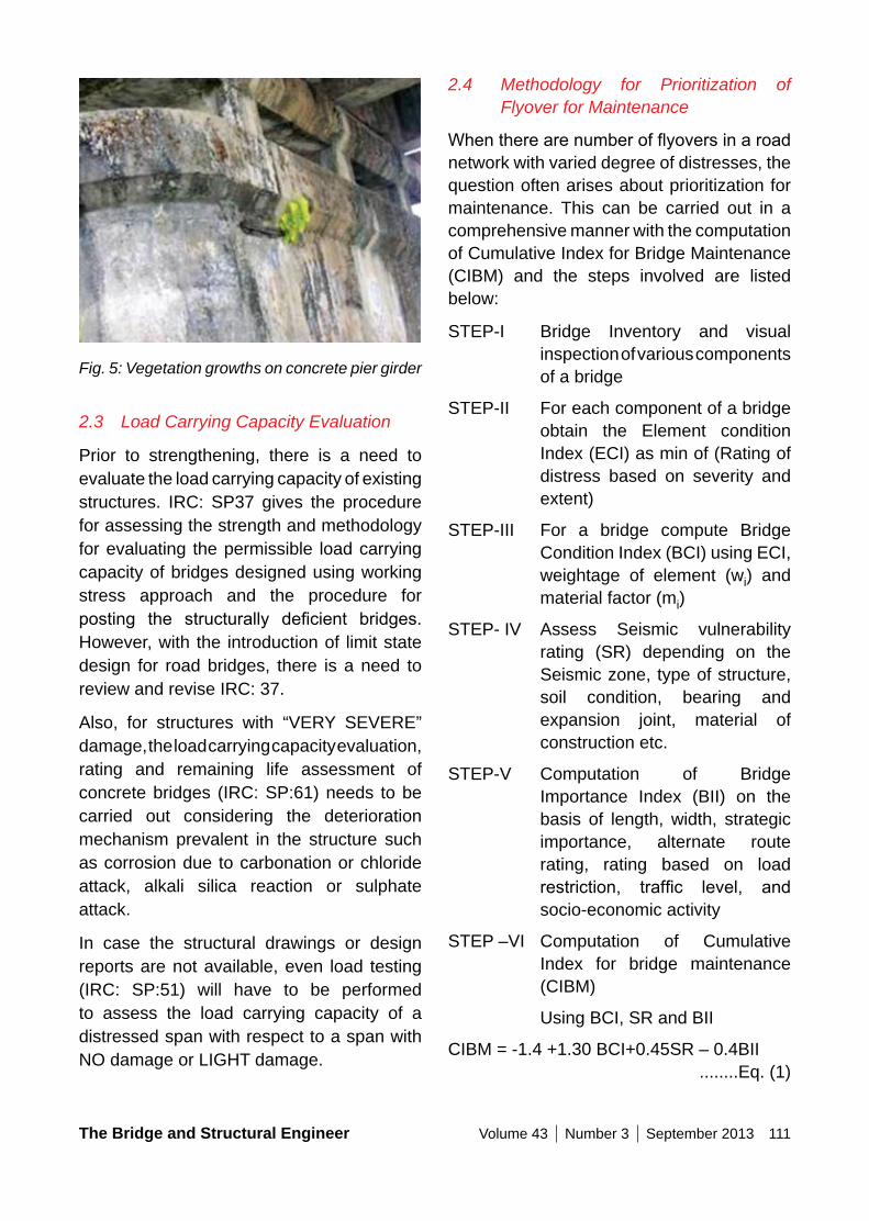
The Bridge and Structural Engineer Volume 43 Number 3 September 2013 111
2.4 Methodology for Prioritization of Flyover for Maintenance
Whentherearenumberofflyoversinaroadnetwork with varied degree of distresses, the question often arises about prioritization for maintenance. This can be carried out in a comprehensive manner with the computation of Cumulative Index for Bridge Maintenance (CIBM) and the steps involved are listed below:
STEP-I Bridge Inventory and visual inspection of various components of a bridge
STEP-II For each component of a bridge obtain the Element condition Index (ECI) as min of (Rating of distress based on severity and extent)
STEP-III For a bridge compute Bridge Condition Index (BCI) using ECI, weightage of element (wi) and material factor (mi)
STEP- IV Assess Seismic vulnerability rating (SR) depending on the Seismic zone, type of structure, soil condition, bearing and expansion joint, material of construction etc.
STEP-V Computation of Bridge Importance Index (BII) on the basis of length, width, strategic importance, alternate route rating, rating based on load restriction, traffic level, andsocio-economic activity
STEP –VI Computation of Cumulative Index for bridge maintenance (CIBM)
Using BCI, SR and BII
CIBM = -1.4 +1.30 BCI+0.45SR – 0.4BII ........Eq. (1)
Fig. 5: Vegetation growths on concrete pier girder
2.3 Load Carrying Capacity Evaluation
Prior to strengthening, there is a need to evaluate the load carrying capacity of existing structures. IRC: SP37 gives the procedure for assessing the strength and methodology for evaluating the permissible load carrying capacity of bridges designed using working stress approach and the procedure for posting the structurally deficient bridges.However, with the introduction of limit state design for road bridges, there is a need to review and revise IRC: 37.
Also, for structures with “VERY SEVERE” damage, the load carrying capacity evaluation, rating and remaining life assessment of concrete bridges (IRC: SP:61) needs to be carried out considering the deterioration mechanism prevalent in the structure such as corrosion due to carbonation or chloride attack, alkali silica reaction or sulphate attack.
In case the structural drawings or design reports are not available, even load testing (IRC: SP:51) will have to be performed to assess the load carrying capacity of a distressed span with respect to a span with NO damage or LIGHT damage.
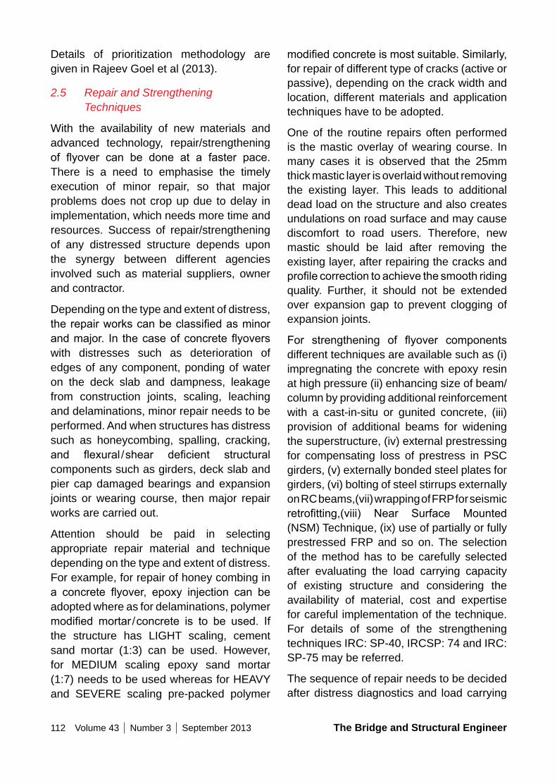
112 Volume 43 Number 3 September 2013 The Bridge and Structural Engineer
modifiedconcreteismostsuitable.Similarly,for repair of different type of cracks (active or passive), depending on the crack width and location, different materials and application techniques have to be adopted.
One of the routine repairs often performed is the mastic overlay of wearing course. In many cases it is observed that the 25mm thick mastic layer is overlaid without removing the existing layer. This leads to additional dead load on the structure and also creates undulations on road surface and may cause discomfort to road users. Therefore, new mastic should be laid after removing the existing layer, after repairing the cracks and profilecorrectiontoachievethesmoothridingquality. Further, it should not be extended over expansion gap to prevent clogging of expansion joints.
For strengthening of flyover componentsdifferent techniques are available such as (i) impregnating the concrete with epoxy resin at high pressure (ii) enhancing size of beam/column by providing additional reinforcement with a cast-in-situ or gunited concrete, (iii) provision of additional beams for widening the superstructure, (iv) external prestressing for compensating loss of prestress in PSC girders, (v) externally bonded steel plates for girders, (vi) bolting of steel stirrups externally on RC beams,(vii) wrapping of FRP for seismic retrofitting,(viii) Near Surface Mounted(NSM) Technique, (ix) use of partially or fully prestressed FRP and so on. The selection of the method has to be carefully selected after evaluating the load carrying capacity of existing structure and considering the availability of material, cost and expertise for careful implementation of the technique. For details of some of the strengthening techniques IRC: SP-40, IRCSP: 74 and IRC: SP-75 may be referred.
The sequence of repair needs to be decided after distress diagnostics and load carrying
Details of prioritization methodology are given in Rajeev Goel et al (2013).
2.5 Repair and Strengthening Techniques
With the availability of new materials and advanced technology, repair/strengthening of flyover can be done at a faster pace.There is a need to emphasise the timely execution of minor repair, so that major problems does not crop up due to delay in implementation, which needs more time and resources. Success of repair/strengthening of any distressed structure depends upon the synergy between different agencies involved such as material suppliers, owner and contractor.
Depending on the type and extent of distress, therepairworkscanbeclassifiedasminorandmajor. In thecaseofconcreteflyoverswith distresses such as deterioration of edges of any component, ponding of water on the deck slab and dampness, leakage from construction joints, scaling, leaching and delaminations, minor repair needs to be performed. And when structures has distress such as honeycombing, spalling, cracking, and flexural /shear deficient structuralcomponents such as girders, deck slab and pier cap damaged bearings and expansion joints or wearing course, then major repair works are carried out.
Attention should be paid in selecting appropriate repair material and technique depending on the type and extent of distress. For example, for repair of honey combing in a concrete flyover, epoxy injection can beadopted where as for delaminations, polymer modified mortar/concrete is to be used. Ifthe structure has LIGHT scaling, cement sand mortar (1:3) can be used. However, for MEDIUM scaling epoxy sand mortar (1:7) needs to be used whereas for HEAVY and SEVERE scaling pre-packed polymer
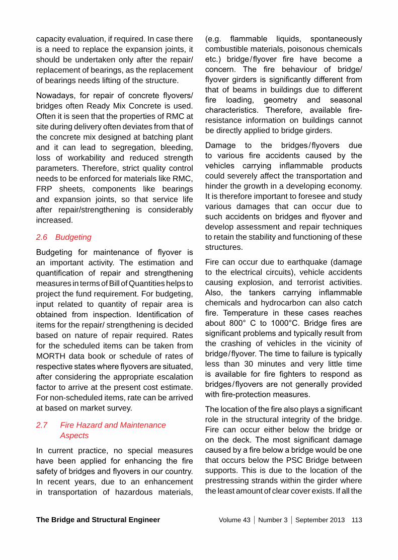
The Bridge and Structural Engineer Volume 43 Number 3 September 2013 113
(e.g. flammable liquids, spontaneouslycombustible materials, poisonous chemicals etc.) bridge/flyover fire have become aconcern. The fire behaviour of bridge/flyovergirders is significantly different fromthat of beams in buildings due to different fire loading, geometry and seasonalcharacteristics. Therefore, available fire-resistance information on buildings cannot be directly applied to bridge girders.
Damage to the bridges/flyovers dueto various fire accidents caused by thevehicles carrying inflammable productscould severely affect the transportation and hinder the growth in a developing economy. It is therefore important to foresee and study various damages that can occur due to suchaccidentsonbridgesandflyoveranddevelop assessment and repair techniques to retain the stability and functioning of these structures.
Fire can occur due to earthquake (damage to the electrical circuits), vehicle accidents causing explosion, and terrorist activities. Also, the tankers carrying inflammablechemicals and hydrocarbon can also catch fire. Temperature in these cases reachesabout 800° C to 1000°C. Bridge fires aresignificantproblemsandtypicallyresultfromthe crashing of vehicles in the vicinity of bridge/flyover.Thetimetofailureistypicallyless than 30 minutes and very little time is available for fire fighters to respond asbridges/flyoversarenotgenerallyprovidedwithfire-protectionmeasures.
Thelocationofthefirealsoplaysasignificantrole in the structural integrity of the bridge. Fire can occur either below the bridge or on the deck. Themost significant damagecausedbyafirebelowabridgewouldbeonethat occurs below the PSC Bridge between supports. This is due to the location of the prestressing strands within the girder where the least amount of clear cover exists. If all the
capacity evaluation, if required. In case there is a need to replace the expansion joints, it should be undertaken only after the repair/ replacement of bearings, as the replacement of bearings needs lifting of the structure.
Nowadays, for repair of concrete flyovers/bridges often Ready Mix Concrete is used. Often it is seen that the properties of RMC at site during delivery often deviates from that of the concrete mix designed at batching plant and it can lead to segregation, bleeding, loss of workability and reduced strength parameters. Therefore, strict quality control needs to be enforced for materials like RMC, FRP sheets, components like bearings and expansion joints, so that service life after repair/strengthening is considerably increased.
2.6 Budgeting
Budgeting for maintenance of flyover isan important activity. The estimation and quantification of repair and strengtheningmeasures in terms of Bill of Quantities helps to project the fund requirement. For budgeting, input related to quantity of repair area is obtained from inspection. Identification ofitems for the repair/ strengthening is decided based on nature of repair required. Rates for the scheduled items can be taken from MORTH data book or schedule of rates of respectivestateswhereflyoversaresituated,after considering the appropriate escalation factor to arrive at the present cost estimate. For non-scheduled items, rate can be arrived at based on market survey.
2.7 Fire Hazard and Maintenance Aspects
In current practice, no special measures have been applied for enhancing the firesafetyofbridgesandflyoversinourcountry.In recent years, due to an enhancement in transportation of hazardous materials,
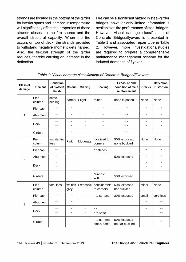
114 Volume 43 Number 3 September 2013 The Bridge and Structural Engineer
Firecanbeasignificanthazardinsteel-girderbridges, however only limited information is availableonfireperformanceofsteelbridges.However, visual damage classification ofConcrete Bridges/flyovers is presented inTable 1 and associated repair type in Table 2. However, more investigations/studies are required to prepare a comprehensive maintenance management scheme for fireinduceddamagesofflyover.
strands are located in the bottom of the girder for interior spans and increase in temperature willsignificantlyaffectthepropertiesofthesestrands closest to the fire source and theoverall structural capacity. When the fireoccurs on top of deck, the strands provided to withstand negative moment gets harped. Also, the flexural strength of the girderreduces, thereby causing an increase in the deflection.
Table 1: Visual damage classification of Concrete Bridges/Flyovers
Class of damage Element
Condition of plaster/
finishColour Crazing Spalling
Exposure and condition of main
reinforcementCracks
Deflection/ Distortion
1
Piercolumn
somepeeling normal Slight minor none exposed None None
Pier cap “ “ “ “ “ “ “ “ “
Abutment “ “ “ “ “ “ “ “ “
Deck “ ““ “
““
““
““
“ ““ “
““
““
Girders “ “ “ “ “
2
Pier column
substantial loss Pink Moderate localized to
corners50% exposed,none buckled
None None
Pier cap “ “ “ patches “ “
Abutment “ “ 50% exposed “ “
Deck “ ““ “
““
““
Girders Minor to soffit 50% exposed
3
Piercolumn
total loss whitish grey
Extensive considerable to corners
50% exposedbar buckled
minor None
Pier cap “ “ “ “ “ to surface 20% exposed small very less
Abutment “ “ “ “ “ “ “
Deck “ ““ “
““
““
“ ““tosoffit
“ “ ““ “
Girders “ to corners, sides,soffit
50% exposedno bar buckled
“ “ “
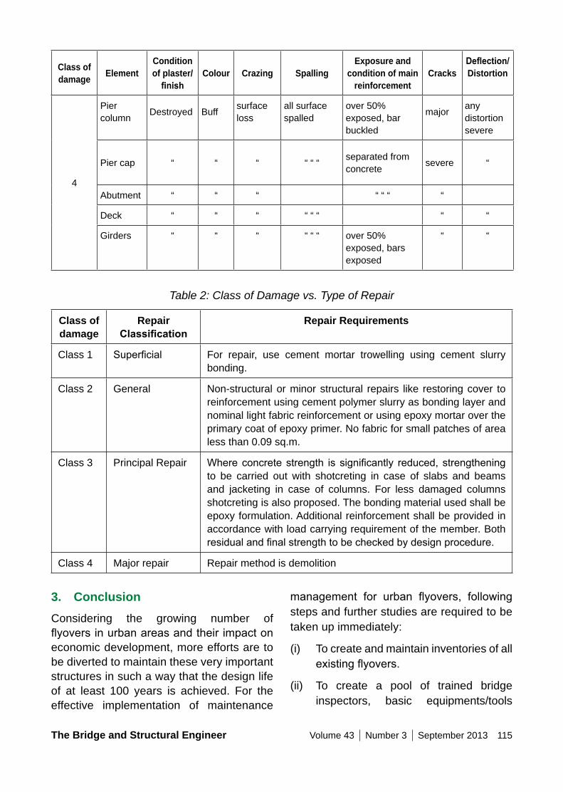
The Bridge and Structural Engineer Volume 43 Number 3 September 2013 115
Class of damage Element
Condition of plaster/
finishColour Crazing Spalling
Exposure and condition of main
reinforcementCracks
Deflection/ Distortion
4
Pier column Destroyed Buff surface
lossall surface spalled
over 50% exposed, bar buckled
major any distortionsevere
Pier cap “ “ “ “ “ “ separated from concrete severe “
Abutment “ “ “ “ “ “ “
Deck “ “ “ “ “ “ “ “
Girders “ “ “ “ “ “ over 50% exposed, bars exposed
“ “
Table 2: Class of Damage vs. Type of Repair
Class of damage
Repair Classification
Repair Requirements
Class 1 Superficial For repair, use cement mortar trowelling using cement slurry bonding.
Class 2 General Non-structural or minor structural repairs like restoring cover to reinforcement using cement polymer slurry as bonding layer and nominal light fabric reinforcement or using epoxy mortar over the primary coat of epoxy primer. No fabric for small patches of area less than 0.09 sq.m.
Class 3 Principal Repair Whereconcretestrength is significantly reduced, strengtheningto be carried out with shotcreting in case of slabs and beams and jacketing in case of columns. For less damaged columns shotcreting is also proposed. The bonding material used shall be epoxy formulation. Additional reinforcement shall be provided in accordance with load carrying requirement of the member. Both residualandfinalstrengthtobecheckedbydesignprocedure.
Class 4 Major repair Repair method is demolition
3. ConclusionConsidering the growing number of flyoversinurbanareasandtheirimpactoneconomic development, more efforts are to be diverted to maintain these very important structures in such a way that the design life of at least 100 years is achieved. For the effective implementation of maintenance
management for urban flyovers, followingsteps and further studies are required to be taken up immediately:
(i) To create and maintain inventories of all existingflyovers.
(ii) To create a pool of trained bridge inspectors, basic equipments/tools
116 Volume 43 Number 3 September 2013 The Bridge and Structural Engineer
References1. IRC: SP-37-2010, “Guidelines for
Evaluation of Load Carrying Capacity”, Indian Roads Congress, New Delhi.
2. IRC: SP-18-1978, “Manual of Bridge Maintenance Inspection”, Indian Roads Congress, New Delhi.
3. IRC: SP-40-1993, “Guidelines on Techniques for Strengthening and Rehabilitation of Bridges”, Indian Roads Congress, New Delhi.
4. IRC: SP: 51-1999, “Guidelines for Load Testing of Bridges”, IRC, New Delhi.
5. IRC: SP-52-1999, “Bridge Inspector’s Reference Manual”, IRC, New Delhi.
6. IRC-SP:61-2002, An Approach Document for Assessment of Remaining Life of Concrete Bridges, IRC, New Delhi.
7. IRC: SP:74-2007, “Guidelines for Repair and Rehabilitation of Steel Bridges, IRC, New Delhi.
8. IRC: SP:75-2008, “Guidelines for Retrofitting of Steel Bridges byPrestressing”, IRC, New Delhi.
9. Rajeev Goel et al (2013), “Development of Critical Infrastructure Information System in GIS Environment for Maintenance of Bridges on National & State Highways”, Report No. CRRI/BAS/GAP-4456/2012-13/01.
10. Sharma et al (2013), “Experiences from Investigation of Expansion Joints and Bearings in Concrete Bridges”, Indian Highways 2013, pp. 67-75.
for inspection and sophisticated NDT equipments.
(iii) To develop effective and economic distress diagnostics techniques for the bridges constructed prestressed precast segmental bridges and steel concrete composite girder bridges.
(iv) To adopt improved techniques for load carrying capacity evaluation with minimumtrafficdisruption.
(v) To develop performance criteria for evaluation of maintenance strategies for RCC, PSC and steel composite structures and also to study their economic aspects for flyovers ofdifferent ages.
(vi) Study the economics and effectiveness of maintenance strategies for RCC, PSC and Steel-concrete composite structures.
(vii) To undertake minimum seismic retrofitting of flyovers by providingcable restrainers, reaction blocks or bearing seat extenders (in longitudinal and transverse direction) to minimise the possibility of unseating of deck.
(viii) More studies are required on investigationandrepairoffiredamagedflyovers.
(ix) To prepare a comprehensive maintenancemanualforurbanflyovers.
AcknowledgementThis paper is published with the permission of Director, CSIR- Central Road Research Institute, New Delhi.
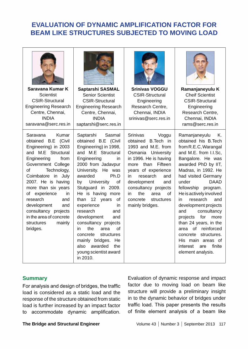
The Bridge and Structural Engineer Volume 43 Number 3 September 2013 117
Saravana Kumar K Scientist
CSIR-Structural Engineering Research
Centre, Chennai, INDIA
Saptarshi SASMAL Senior Scientist CSIR-Structural
Engineering Research Centre, Chennai,
Srinivas VoGGU CSIR-Structural
Engineering Research Centre, Chennai, INDIA
Ramanjaneyulu K Cheif Scientist
CSIR-Structural Engineering
Research Centre, Chennai, INDIA
Saravana Kumar obtained B.E (Civil Engineering) in 2003 and M.E Structural Engineering from Government College of Technology, Coimbatore in July 2007. He is having more than six years of experience in research and development and consultancy projects in the area of concrete structures mainly bridges.
Saptarshi Sasmal obtained B.E (Civil Engineering) in 1998, and M.E Structural Engineering in 2000 from Jadavpur University. He was awarded Ph.D by University of Stutguard in 2009. He is having more than 12 years of experience in research and development and consultancy projects in the area of concrete structures mainly bridges. He also awarded the young scientist award in 2010.
Srinivas Voggu obtained B.Tech in 1993 and M.E. from Osmania University in 1996. He is having more than Fifteen years of experience in research and development and consultancy projects in the area of concrete structures mainly bridges.
Ramanjaneyulu K. obtained his B.Tech from R.E.C, Warangal and M.E. from I.I.Sc, Bangalore. He was awarded PhD by IIT, Madras, in 1992. He had visited Germany under DAAD fellowship program. He is actively involved in research and development projects and consultancy projects for more than 24 years, in the area of reinforced concrete structures. His main areas of interest are finiteelement analysis.
EVALUATIon oF DynAMIC AMPLIFICATIon FACToR FoR BEAM LIKE STRUCTURES SUBJECTED To MoVInG LoAD
SummaryForanalysisanddesignofbridges,thetrafficload is considered as a static load and the response of the structure obtained from static load is further increased by an impact factor to accommodate dynamic amplification.
Evaluation of dynamic response and impact factor due to moving load on beam like structure will provide a preliminary insight in to the dynamic behavior of bridges under traffic load.Thispaperpresents the resultsof finite element analysis of a beam like
118 Volume 43 Number 3 September 2013 The Bridge and Structural Engineer
and bridges. On one hand, a vehicle running at high speed induces dynamic impactonthebridgestructures, influencingtheir working state and service life. On the other hand, vibration of the bridge in turn affects the running stability and safety of the vehicle. Thus, it becomes an important factor to evaluate the dynamic parameters of bridge. Responses of bridge under moving loads (dynamic amplification factors) havebeen considered as one of the important design requirements from bridges. Classical contributions were made by Timoshenko [1] who examined a simply supported beam under a constant moving force using the expansion of Eigen functions. Further, Timoshenko [2] extended the problem with moving harmonic force. Wen [3] solved the problem of a two-axle moving load on a beam by considering the bridge as a beam of uniform mass and the vehicle as a sprung mass with two axles.
An approximation was made as the dynamic deflection of the beam at any time wasproportional to its instantaneous static deflection due to the moving load. Fryba[4] extensively investigated the vibration of simply supported beam subjected to various moving loadings. Based on these studies, a variety of standards such as IRC-6 [5], Eurocode [6] for bridge design consider the dynamic effect of a moving load by introducing the impact factor, which indicates the difference between dynamic and static responses of bridges subjected to moving load.
Chang [7] discussed the vibrational behavior of simply supported highway girder bridges with rough surfaces due to heavy trucks. An appropriate vehicle model for vibrational analysis of bridges was established by comparing dynamic responses from four different vehicle models and impact factors were calculated using the suggested vehicle
structure subjected to moving load. Finite element modeling adopted in this study has the capability to represent the moving load with velocities. Transient dynamic analysis is carried out to analyze the beam subjected to a single moving load with constant speed. Influenceofvariousparameterssuchas:(i)speed of the vehicle, (ii) span of the bridge, (iii) intensity of concentrated load, (iv) moment of inertia of beam, (v) added mass from vehicle, (vi) number of concentrated load at constant spacing and (vii) spacing between the axle load,on thedynamicamplification factor isstudied. The Effect of Inertia force, Centripetal force and corolis force of the moving mass on the dynamic amplification factor werealso studied. Finally, the implications of these parametersondynamicamplification factorare discussed.
Key words: Impact Factor; Transient dynamic Analysis; Dynamic AmplificationFactor; Moving Load; Bridges; Time Integration; Numerical Analysis.
1. IntroductionHighways and Railways play an important role for the comfortable and economic transportation of the freight and passengers. To cater to the increasing demand, transportation authorities are adopting modern techniques to increase speed and to improveeconomy,strategiesandefficiency.For example, Indian Railway is planning to provide high speed rail network among major cities using dedicated freight corridors. To determine structural responses due to enhanced demand, dynamic interaction among moving vehicle, track and structure should be studied carefully and mere multiplication of DAF (specified in differentstandards) on static analysis response may not be always correct. Increase in speed of vehicle emphasizes the necessity to study the dynamic interaction between vehicles
The Bridge and Structural Engineer Volume 43 Number 3 September 2013 119
sufficientlyconsideredinthecurrentdesignstandards. The dynamic effects of wheel loads are accounted by scaling the static loads with single impact factor which is generally related to the bridge length even though other parameters of vehicle and bridge also affect the response. The formulae of impact factorspecified indifferentcodeshavebeenfoundtobeoversimplifiedandinmany cases, misrepresent the dynamics in the bridge-vehicle interaction. Accurate and practical methods are needed for diagnostics and verification of the dynamic effects onbridges, as well as for computation of impact factor. In view of this, in the present study, a detailed transient dynamic analysis has been carried out to evaluate the dynamic amplification factors for bridges due tothe movement of traffic load with differentspeeds and geometric configurations. Tominimize the computational effort, the bridge hasbeenmodeledasabeamandthetrafficload has been assumed to be point load. The response obtained from the finite elementmodel used in this study has been firstvalidated with those reported in literature and with classical analysis. The effect of inertia force, centripetal force and corolis force due to moving mass on the beam was studied. Further, the validated model has been used foranexhaustivestudywheretheinfluenceof various parameters such as: (i) speed of the vehicle, (ii) span of the bridge, (iii) intensity of concentrated load, (iv) moment of inertia of beam, (v) added mass from vehicle, (vi) number of concentrated load at constant spacing and (vii) spacing between theaxle load,on thedynamicamplificationfactor is investigated. For ready reference to the readers, a brief on the classical- and numerical- approach to calculate the DAFs due to a moving load has been presented first. It is followed by the validation studyand parametric studies in the preceding sections.
model with different speeds, deck roughness and span lengths. The results were compared withthevaluesspecifiedbyseveralstandardcodes and it has been found that the current design codes tend to underestimate impact factors especially in long-span bridges with rough decks. Yang et al. [8] computed the impact factor for vehicles moving over simple and continuous beams and showed that impact factors for different bridge responses like moment, support reactions anddeflectionsarenotsimilarandtheyhavesuggested different formulas for the impact factor. It has been concluded that the impact factorforthedeflections,bendingmomentsand shear forces at the mid points of simple beams are linearly proportional to the speed parameter.
YangandWu.[9]derivedtheversatilefiniteelement that is capable of treating various vehicle bridge interaction (VBI) effects. The element is versatile since it allows to deal with vehicle models of various complexities, ranging from the moving load, moving mass, sprung mass to suspended rigid bar and others. Saravana Kumar and Ramanjaneyulu [10] studied the behaviour of vehicle-track-bridge interaction by modeling threedimensionalsolidfiniteelementmodelof a typical railway bridge along with rail and wheeltofindtheresponseduetomovementof locomotive over the bridge. Hamidi and Danshjoo [11] studied the effects of various parameters including speed, train axle distance, the number of axles and span lengths on dynamic responses of railway steel bridges and also reported variation of impact factorvalueswith theseparameters. İsmailEsen [17] studied the dynamic behavior of beam carrying the moving accelerating mass by incorporating the effect of Inertia force, Centripetal force and Corolis Force.
The dynamic nature of vehicle loads and vehicle-track-bridge interaction is not
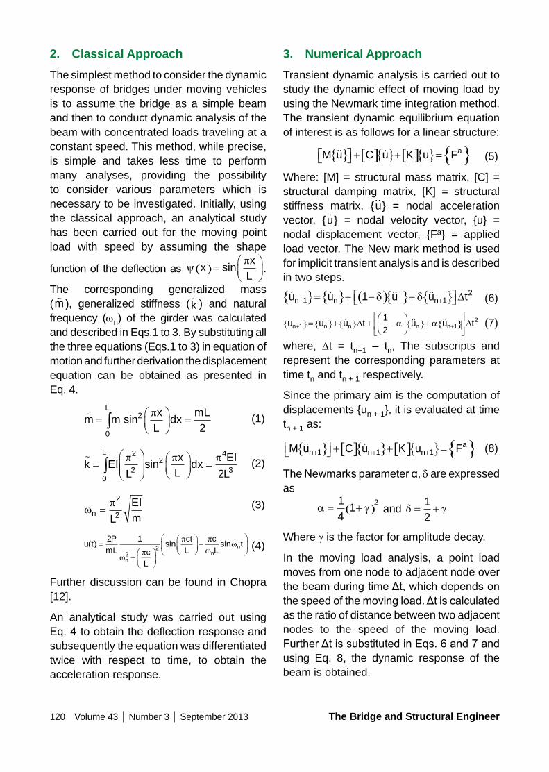
120 Volume 43 Number 3 September 2013 The Bridge and Structural Engineer
3. numerical ApproachTransient dynamic analysis is carried out to study the dynamic effect of moving load by using the Newmark time integration method. The transient dynamic equilibrium equation of interest is as follows for a linear structure:
{ } [ ]{ } [ ]{ } { }aM u C u K u F + + = (5)
Where: [M] = structural mass matrix, [C] = structural damping matrix, [K] = structural stiffness matrix, {u
..} = nodal acceleration
vector, {u.} = nodal velocity vector, {u} =
nodal displacement vector, {Fa} = applied load vector. The New mark method is used for implicit transient analysis and is described in two steps.
{ } { } ( ){ } { } 2n 1 n n 1u u 1 u u t+ + = + − δ + δ D (6)
u u u t u u tn n n n n+ +{ }= { }+{ } + −
{ }+ { }
1 1
212
D Da a (7)
where, Dt = tn+1 – tn, The subscripts and represent the corresponding parameters at time tn and tn + 1 respectively.
Since the primary aim is the computation of displacements {un + 1}, it is evaluated at time tn + 1 as:
{ } [ ]{ } [ ]{ } { }an 1 n 1 n 1M u C u K u F+ + + + + = (8)
TheNewmarksparameterα,δ are expressed as
a g= +( )14
12 and δ g= +
12
Where g is the factor for amplitude decay.
In the moving load analysis, a point load moves from one node to adjacent node over thebeamduringtimeΔt,whichdependsonthespeedofthemovingload.Δtiscalculatedas the ratio of distance between two adjacent nodes to the speed of the moving load. FurtherΔtissubstitutedinEqs.6and7andusing Eq. 8, the dynamic response of the beam is obtained.
2. Classical ApproachThe simplest method to consider the dynamic response of bridges under moving vehicles is to assume the bridge as a simple beam and then to conduct dynamic analysis of the beam with concentrated loads traveling at a constant speed. This method, while precise, is simple and takes less time to perform many analyses, providing the possibility to consider various parameters which is necessary to be investigated. Initially, using the classical approach, an analytical study has been carried out for the moving point load with speed by assuming the shape
functionof thedeflectionas yπ
xx
L( )=
sin .
The corresponding generalized mass (m~ ), generalized stiffness (k
~ ) and natural frequency (wn) of the girder was calculated and described in Eqs.1 to 3. By substituting all the three equations (Eqs.1 to 3) in equation of motion and further derivation the displacement equation can be obtained as presented in Eq. 4.
m mx
Ldx
mLL~
sin=
=∫
0
2
2π (1)
k EIL
xL
dxEI
L
L~
sin=
=∫
0
2
22
4
32
π π π (2)
wπ
nL
EIm
=2
2 (3)
u tP
mL cL
ctL
cL
t
nn
n( ) sin sin=
−
−
2 1
22
wπ
π πw
w (4)
Further discussion can be found in Chopra [12].
An analytical study was carried out using Eq.4toobtainthedeflectionresponseandsubsequently the equation was differentiated twice with respect to time, to obtain the acceleration response.
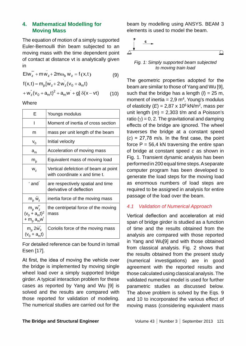
The Bridge and Structural Engineer Volume 43 Number 3 September 2013 121
beam by modelling using ANSYS. BEAM 3 elements is used to model the beam.
Fig. 1: Simply supported beam subjected to moving train load
The geometric properties adopted for the beam are similar to those of Yang and Wu [9], such that the bridge has a length (l) = 25 m, moment of inertia = 2,9 m4, Young’s modulus of elasticity (E) = 2,87 x 10⁶ kN/m2, mass per unit length (m) = 2,303 t/m and a Poisson’s ratio (g) = 0, 2. The gravitational and damping effects of the bridge are ignored. The wheel traverses the bridge at a constant speed (c)=27,78m/s. In thefirst case, thepointforce P = 56,4 kN traversing the entire span of bridge at constant speed c as shown in Fig. 1. Transient dynamic analysis has been performed in 200 equal time steps. A separate computer program has been developed to generate the load steps for the moving load as enormous numbers of load steps are required to be assigned in analysis for entire passage of the load over the beam.
4.1 Validation of Numerical Approach
Vertical deflection and acceleration at midspan of bridge girder is studied as a function of time and the results obtained from the analysis are compared with those reported in Yang and Wu[9] and with those obtained from classical analysis. Fig. 2 shows that the results obtained from the present study (numerical investigations) are in good agreement with the reported results and those calculated using classical analysis. The validated numerical model is used for further parametric studies as discussed below. The above problem is solved by the Eqs. 9 and 10 to incorporated the various effect of moving mass (considering equivalent mass
4. Mathematical Modelling for Moving Mass
The equation of motion of a simply supported Euler-Bernoulli thin beam subjected to an moving mass with the time dependent point of contact at distance vt is analytically given in
EIw mw m w f x tz z b z’’’’
.. .,+ + = ( )2 w (9)
f x t m w w v a tp z z m( , ) [ ( )..
’.
= + +2 0
+ + + + −w v a t a w g x vtz m m’’ ’( ) ] ( )0
2 δ (10)
Where
E Youngs modulus
I Moment of inertia of cross section
m mass per unit length of the beam
v0 Initial velocity
am Acceleration of moving mass
mp Equivalent mass of moving load
wz Vertical defelction of beam at point with coordinate x and time t.
‘ and. are respectively spatial and time
derivativeofdeflection
mp w..
z inertia force of the moving mass
mp w′′z
(v0 + amt)2 + mp amw′
the centripetal force of the moving mass
mp 2w. ′z
(v0 + amt)Coriolis force of the moving mass
For detailed reference can be found in Ismail Esen [17].
Atfirst, theideaofmovingthevehicleoverthe bridge is implemented by moving single wheel load over a simply supported bridge girder. A typical interaction problem for these cases as reported by Yang and Wu [9] is solved and the results are compared with those reported for validation of modeling. The numerical studies are carried out for the
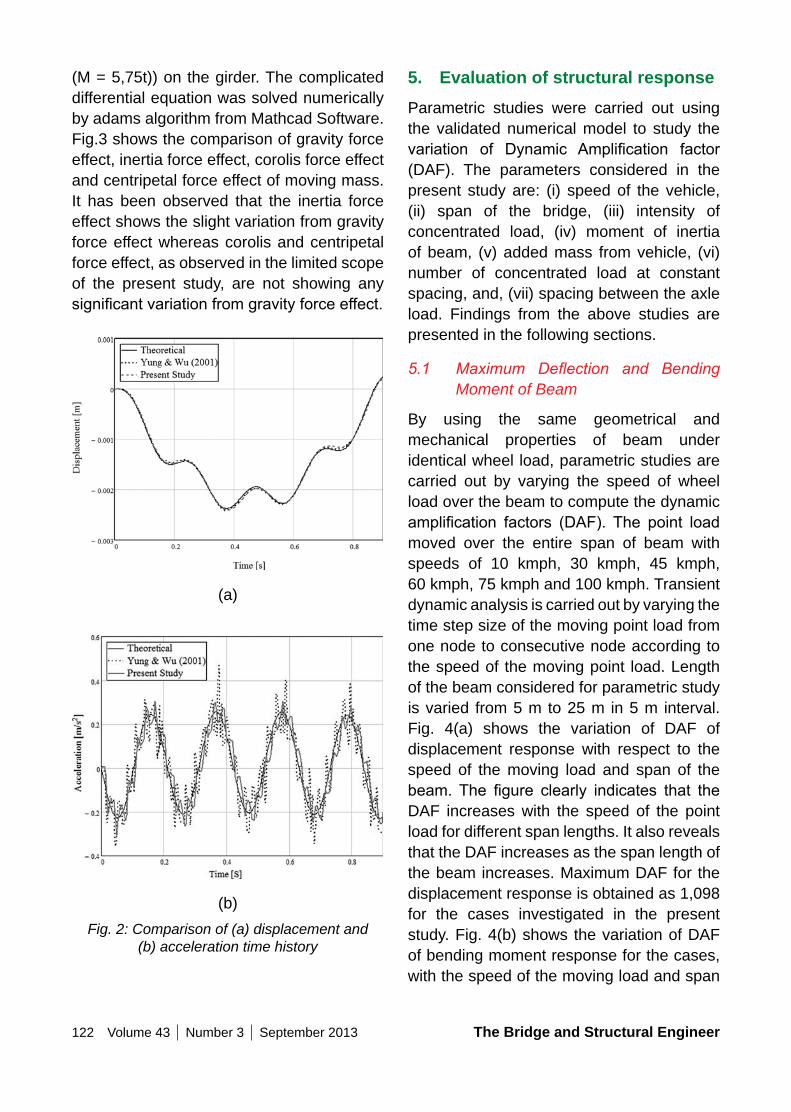
122 Volume 43 Number 3 September 2013 The Bridge and Structural Engineer
5. Evaluation of structural responseParametric studies were carried out using the validated numerical model to study the variation of Dynamic Amplification factor(DAF). The parameters considered in the present study are: (i) speed of the vehicle, (ii) span of the bridge, (iii) intensity of concentrated load, (iv) moment of inertia of beam, (v) added mass from vehicle, (vi) number of concentrated load at constant spacing, and, (vii) spacing between the axle load. Findings from the above studies are presented in the following sections.
5.1 Maximum Deflection and Bending Moment of Beam
By using the same geometrical and mechanical properties of beam under identical wheel load, parametric studies are carried out by varying the speed of wheel load over the beam to compute the dynamic amplification factors (DAF). The point loadmoved over the entire span of beam with speeds of 10 kmph, 30 kmph, 45 kmph, 60 kmph, 75 kmph and 100 kmph. Transient dynamic analysis is carried out by varying the time step size of the moving point load from one node to consecutive node according to the speed of the moving point load. Length of the beam considered for parametric study is varied from 5 m to 25 m in 5 m interval. Fig. 4(a) shows the variation of DAF of displacement response with respect to the speed of the moving load and span of the beam. The figure clearly indicates that theDAF increases with the speed of the point load for different span lengths. It also reveals that the DAF increases as the span length of the beam increases. Maximum DAF for the displacement response is obtained as 1,098 for the cases investigated in the present study. Fig. 4(b) shows the variation of DAF of bending moment response for the cases, with the speed of the moving load and span
(M = 5,75t)) on the girder. The complicated differential equation was solved numerically by adams algorithm from Mathcad Software. Fig.3 shows the comparison of gravity force effect, inertia force effect, corolis force effect and centripetal force effect of moving mass. It has been observed that the inertia force effect shows the slight variation from gravity force effect whereas corolis and centripetal force effect, as observed in the limited scope of the present study, are not showing any significantvariationfromgravityforceeffect.
(a)
(b)Fig. 2: Comparison of (a) displacement and
(b) acceleration time history
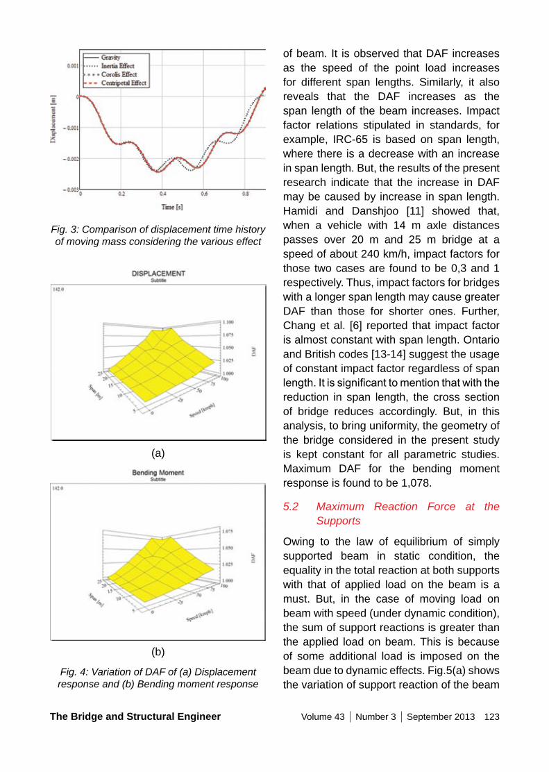
The Bridge and Structural Engineer Volume 43 Number 3 September 2013 123
Fig. 4: Variation of DAF of (a) Displacement response and (b) Bending moment response
of beam. It is observed that DAF increases as the speed of the point load increases for different span lengths. Similarly, it also reveals that the DAF increases as the span length of the beam increases. Impact factor relations stipulated in standards, for example, IRC-65 is based on span length, where there is a decrease with an increase in span length. But, the results of the present research indicate that the increase in DAF may be caused by increase in span length. Hamidi and Danshjoo [11] showed that, when a vehicle with 14 m axle distances passes over 20 m and 25 m bridge at a speed of about 240 km/h, impact factors for those two cases are found to be 0,3 and 1 respectively. Thus, impact factors for bridges with a longer span length may cause greater DAF than those for shorter ones. Further, Chang et al. [6] reported that impact factor is almost constant with span length. Ontario and British codes [13-14] suggest the usage of constant impact factor regardless of span length.Itissignificanttomentionthatwiththereduction in span length, the cross section of bridge reduces accordingly. But, in this analysis, to bring uniformity, the geometry of the bridge considered in the present study is kept constant for all parametric studies. Maximum DAF for the bending moment response is found to be 1,078.
5.2 Maximum Reaction Force at the Supports
Owing to the law of equilibrium of simply supported beam in static condition, the equality in the total reaction at both supports with that of applied load on the beam is a must. But, in the case of moving load on beam with speed (under dynamic condition), the sum of support reactions is greater than the applied load on beam. This is because of some additional load is imposed on the beam due to dynamic effects. Fig.5(a) shows the variation of support reaction of the beam
Fig. 3: Comparison of displacement time history of moving mass considering the various effect
(a)
(b)
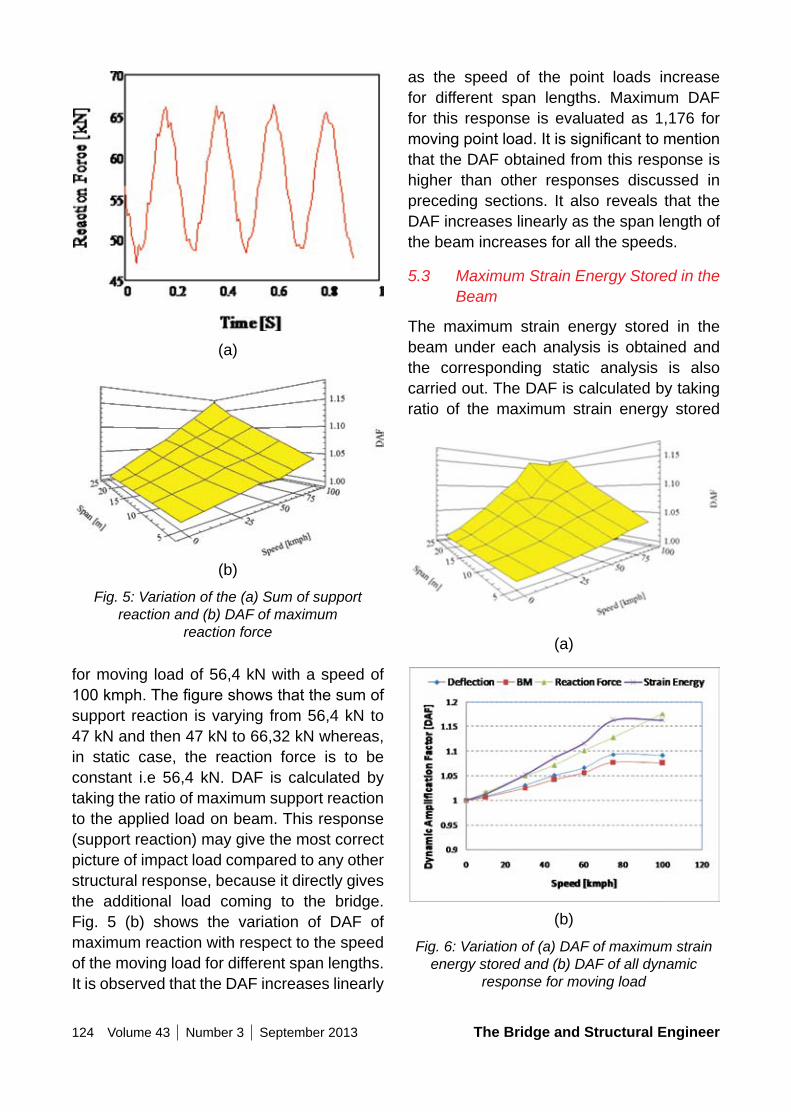
124 Volume 43 Number 3 September 2013 The Bridge and Structural Engineer
as the speed of the point loads increase for different span lengths. Maximum DAF for this response is evaluated as 1,176 for movingpointload.Itissignificanttomentionthat the DAF obtained from this response is higher than other responses discussed in preceding sections. It also reveals that the DAF increases linearly as the span length of the beam increases for all the speeds.
5.3 Maximum Strain Energy Stored in the Beam
The maximum strain energy stored in the beam under each analysis is obtained and the corresponding static analysis is also carried out. The DAF is calculated by taking ratio of the maximum strain energy stored
Fig. 5: Variation of the (a) Sum of support reaction and (b) DAF of maximum
reaction force
(a)
(a)
(b)
(b)
for moving load of 56,4 kN with a speed of 100kmph.Thefigureshowsthatthesumofsupport reaction is varying from 56,4 kN to 47 kN and then 47 kN to 66,32 kN whereas, in static case, the reaction force is to be constant i.e 56,4 kN. DAF is calculated by taking the ratio of maximum support reaction to the applied load on beam. This response (support reaction) may give the most correct picture of impact load compared to any other structural response, because it directly gives the additional load coming to the bridge. Fig. 5 (b) shows the variation of DAF of maximum reaction with respect to the speed of the moving load for different span lengths. It is observed that the DAF increases linearly
Fig. 6: Variation of (a) DAF of maximum strain energy stored and (b) DAF of all dynamic
response for moving load
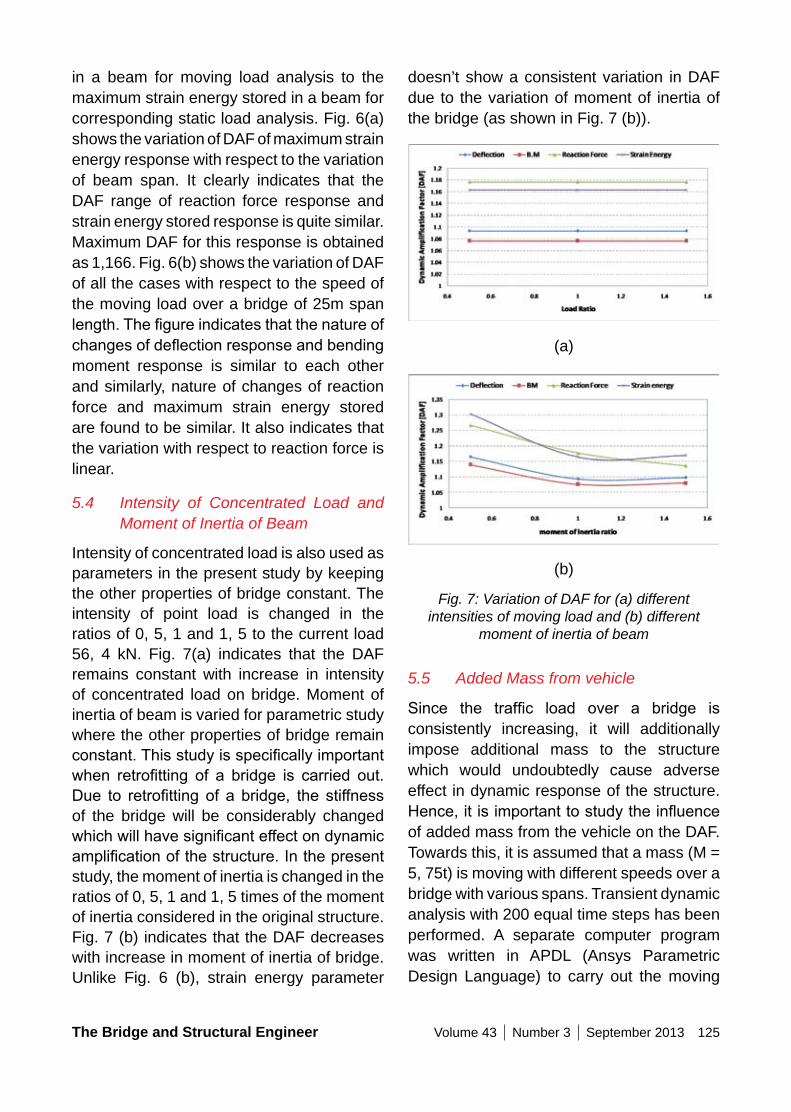
The Bridge and Structural Engineer Volume 43 Number 3 September 2013 125
doesn’t show a consistent variation in DAF due to the variation of moment of inertia of the bridge (as shown in Fig. 7 (b)).
(a)
(b)
Fig. 7: Variation of DAF for (a) different intensities of moving load and (b) different
moment of inertia of beam
5.5 Added Mass from vehicle
Since the traffic load over a bridge isconsistently increasing, it will additionally impose additional mass to the structure which would undoubtedly cause adverse effect in dynamic response of the structure. Hence,itisimportanttostudytheinfluenceof added mass from the vehicle on the DAF. Towards this, it is assumed that a mass (M = 5, 75t) is moving with different speeds over a bridge with various spans. Transient dynamic analysis with 200 equal time steps has been performed. A separate computer program was written in APDL (Ansys Parametric Design Language) to carry out the moving
in a beam for moving load analysis to the maximum strain energy stored in a beam for corresponding static load analysis. Fig. 6(a) shows the variation of DAF of maximum strain energy response with respect to the variation of beam span. It clearly indicates that the DAF range of reaction force response and strain energy stored response is quite similar. Maximum DAF for this response is obtained as 1,166. Fig. 6(b) shows the variation of DAF of all the cases with respect to the speed of the moving load over a bridge of 25m span length.Thefigureindicatesthatthenatureofchangesofdeflectionresponseandbendingmoment response is similar to each other and similarly, nature of changes of reaction force and maximum strain energy stored are found to be similar. It also indicates that the variation with respect to reaction force is linear.
5.4 Intensity of Concentrated Load and Moment of Inertia of Beam
Intensity of concentrated load is also used as parameters in the present study by keeping the other properties of bridge constant. The intensity of point load is changed in the ratios of 0, 5, 1 and 1, 5 to the current load 56, 4 kN. Fig. 7(a) indicates that the DAF remains constant with increase in intensity of concentrated load on bridge. Moment of inertia of beam is varied for parametric study where the other properties of bridge remain constant.Thisstudyisspecificallyimportantwhen retrofitting of a bridge is carried out.Due to retrofitting of a bridge, the stiffnessof the bridge will be considerably changed whichwillhavesignificanteffectondynamicamplificationofthestructure.Inthepresentstudy, the moment of inertia is changed in the ratios of 0, 5, 1 and 1, 5 times of the moment of inertia considered in the original structure. Fig. 7 (b) indicates that the DAF decreases with increase in moment of inertia of bridge. Unlike Fig. 6 (b), strain energy parameter
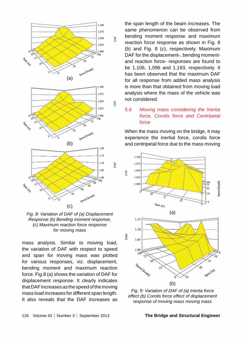
126 Volume 43 Number 3 September 2013 The Bridge and Structural Engineer
the span length of the beam increases. The same phenomenon can be observed from bending moment response and maximum reaction force response as shown in Fig. 8 (b) and Fig. 8 (c), respectively. Maximum DAF for the displacement-, bending moment- and reaction force- responses are found to be 1,106, 1,096 and 1,193, respectively. It has been observed that the maximum DAF for all response from added mass analysis is more than that obtained from moving load analysis where the mass of the vehicle was not considered.
5.6 Moving mass considering the Inertia force, Corolis force and Centripetal force
When the mass moving on the bridge, it may experience the inertial force, corolis force and centripetal force due to the mass moving
Fig. 8: Variation of DAF of (a) Displacement Response (b) Bending moment response,
(c) Maximum reaction force response for moving mass
(a)
(a)
(b)
(b)
(c)
mass analysis. Similar to moving load, the variation of DAF with respect to speed and span for moving mass was plotted for various responses, viz. displacement, bending moment and maximum reaction force. Fig.8 (a) shows the variation of DAF for displacement response. It clearly indicates that DAF increases as the speed of the moving mass load increases for different span length. It also reveals that the DAF increases as
Fig. 9: Variation of DAF of (a) Inertia force effect (b) Corolis force effect of displacement
response of moving mass moving mass
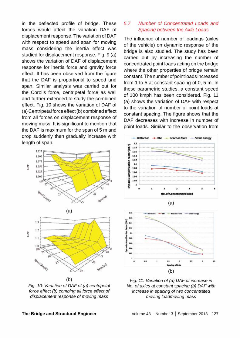
The Bridge and Structural Engineer Volume 43 Number 3 September 2013 127
5.7 Number of Concentrated Loads and Spacing between the Axle Loads
The influenceofnumberof loadings (axlesof the vehicle) on dynamic response of the bridge is also studied. The study has been carried out by increasing the number of concentrated point loads acting on the bridge where the other properties of bridge remain constant. The number of point loads increased from 1 to 5 at constant spacing of 0, 5 m. In these parametric studies, a constant speed of 100 kmph has been considered. Fig. 11 (a) shows the variation of DAF with respect to the variation of number of point loads at constantspacing.ThefigureshowsthattheDAF decreases with increase in number of point loads. Similar to the observation from
in the deflected profile of bridge. Theseforces would affect the variation DAF of displacement response. The variation of DAF with respect to speed and span for moving mass considering the inertia effect was studied for displacement response. Fig. 9 (a) shows the variation of DAF of displacement response for inertia force and gravity force effect.Ithasbeenobservedfromthefigurethat the DAF is proportional to speed and span. Similar analysis was carried out for the Corolis force, centripetal force as well and further extended to study the combined effect. Fig. 10 shows the variation of DAF of (a) Centripetal force effect (b) combined effect from all forces on displacement response of movingmass.Itissignificanttomentionthatthe DAF is maximum for the span of 5 m and drop suddenly then gradually increase with length of span.
(a)
(b)Fig. 10: Variation of DAF of (a) centripetal force effect (b) combing all force effect of displacement response of moving mass
Fig. 11: Variation of (a) DAF of increase in No. of axles at constant spacing (b) DAF with
increase in spacing of two concentrated moving loadmoving mass
(a)
(b)
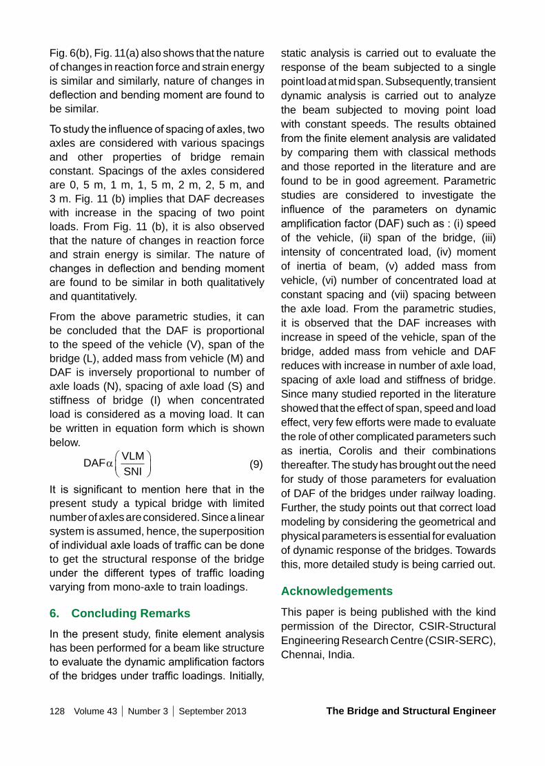
128 Volume 43 Number 3 September 2013 The Bridge and Structural Engineer
static analysis is carried out to evaluate the response of the beam subjected to a single point load at mid span. Subsequently, transient dynamic analysis is carried out to analyze the beam subjected to moving point load with constant speeds. The results obtained fromthefiniteelementanalysisarevalidatedby comparing them with classical methods and those reported in the literature and are found to be in good agreement. Parametric studies are considered to investigate the influence of the parameters on dynamicamplificationfactor(DAF)suchas:(i)speedof the vehicle, (ii) span of the bridge, (iii) intensity of concentrated load, (iv) moment of inertia of beam, (v) added mass from vehicle, (vi) number of concentrated load at constant spacing and (vii) spacing between the axle load. From the parametric studies, it is observed that the DAF increases with increase in speed of the vehicle, span of the bridge, added mass from vehicle and DAF reduces with increase in number of axle load, spacing of axle load and stiffness of bridge. Since many studied reported in the literature showed that the effect of span, speed and load effect, very few efforts were made to evaluate the role of other complicated parameters such as inertia, Corolis and their combinations thereafter. The study has brought out the need for study of those parameters for evaluation of DAF of the bridges under railway loading. Further, the study points out that correct load modeling by considering the geometrical and physical parameters is essential for evaluation of dynamic response of the bridges. Towards this, more detailed study is being carried out.
AcknowledgementsThis paper is being published with the kind permission of the Director, CSIR-Structural Engineering Research Centre (CSIR-SERC), Chennai, India.
Fig. 6(b), Fig. 11(a) also shows that the nature of changes in reaction force and strain energy is similar and similarly, nature of changes in deflectionandbendingmomentarefoundtobe similar.
Tostudytheinfluenceofspacingofaxles,twoaxles are considered with various spacings and other properties of bridge remain constant. Spacings of the axles considered are 0, 5 m, 1 m, 1, 5 m, 2 m, 2, 5 m, and 3 m. Fig. 11 (b) implies that DAF decreases with increase in the spacing of two point loads. From Fig. 11 (b), it is also observed that the nature of changes in reaction force and strain energy is similar. The nature of changes indeflectionandbendingmomentare found to be similar in both qualitatively and quantitatively.
From the above parametric studies, it can be concluded that the DAF is proportional to the speed of the vehicle (V), span of the bridge (L), added mass from vehicle (M) and DAF is inversely proportional to number of axle loads (N), spacing of axle load (S) and stiffness of bridge (I) when concentrated load is considered as a moving load. It can be written in equation form which is shown below.
DAFVLMSNI
a
(9)
It is significant tomention here that in thepresent study a typical bridge with limited number of axles are considered. Since a linear system is assumed, hence, the superposition ofindividualaxleloadsoftrafficcanbedoneto get the structural response of the bridge under the different types of traffic loadingvarying from mono-axle to train loadings.
6. Concluding RemarksIn thepresentstudy,finiteelementanalysishas been performed for a beam like structure toevaluatethedynamicamplificationfactorsofthebridgesundertrafficloadings.Initially,
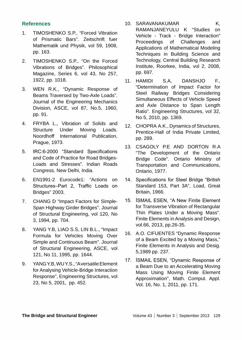
The Bridge and Structural Engineer Volume 43 Number 3 September 2013 129
10. SARAVANAKUMAR K, RAMANJANEYULU K “Studies on Vehicle - Track - Bridge Interaction” Proceedings of Challenges and Applications of Mathematical Modeling Techniques in Building Science and Technology, Central Building Research Institute, Roorkee, India, vol 2, 2008, pp. 697.
11. HAMIDI S.A, DANSHJO F., “Determination of Impact Factor for Steel Railway Bridges Considering Simultaneous Effects of Vehicle Speed and Axle Distance to Span Length Ratio”. Engineering Structures, vol 32, No 5, 2010, pp. 1369.
12. CHOPRA A.K., Dynamics of Structures, Prentice-Hall of India Private Limited, pp. 289.
13. CSAGOLY P.E AND DORTON R.A “The Development of the Ontario Bridge Code”. Ontario Ministry of Transportation and Communications, Ontario, 1977.
14. Specifications forSteelBridge “BritishStandard 153, Part 3A”, Load, Great Britain, 1966.
15. İSMAILESEN, “ANewFiniteElementfor Transverse Vibration of Rectangular Thin Plates Under a Moving Mass”. Finite Elements in Analysis and Design, vol.66, 2013, pp.26-35.
16. A.O. CIFUENTES “Dynamic Response of a Beam Excited by a Moving Mass,” Finite Elements in Analysis and Desig. 5,1989 pp. 237.
17. İSMAILESEN,“DynamicResponseofa Beam Due to an Accelerating Moving Mass Using Moving Finite Element Approximation”, Math. Comput. Appl. Vol. 16, No. 1, 2011, pp. 171.
References1. TIMOSHENKO S.P., “Forced Vibration
of Prismatic Bars”. Zeitschrift fuer Mathematik und Physik, vol 59, 1908, pp. 163.
2. TIMOSHENKO S.P., “On the Forced Vibrations of Bridges”. Philosophical Magazine, Series 6, vol 43, No 257, 1922, pp. 1018.
3. WEN R.K., “Dynamic Response of Beams Traversed by Two-Axle Loads”. Journal of the Engineering Mechanics Division, ASCE, vol 87, No.5, 1960, pp. 91.
4. FRYBA L., Vibration of Solids and Structure Under Moving Loads. Noordhoff International Publication, Prague, 1973.
5. IRC:6-2000 “Standard Specificationsand Code of Practice for Road Bridges-Loads and Stresses”. Indian Roads Congress. New Delhi, India.
6. EN1991-2 Eurocode1: “Actions on Structures–Part 2, Traffic Loads onBridges” 2003.
7. CHANG D “Impact Factors for Simple-Span Highway Girder Bridges”. Journal of Structural Engineering, vol 120, No 3, 1994, pp. 704.
8. YANG Y.B, LIAO S.S, LIN B.L., “Impact Formula for Vehicles Moving Over Simple and Continuous Beam”. Journal of Structural Engineering, ASCE, vol 121, No 11, 1995, pp. 1644.
9. YANG Y.B, WU Y.S., “A versatile Element for Analysing Vehicle-Bridge Interaction Response”, Engineering Structures, vol 23, No 5, 2001, pp. 452.
130 Volume 43 Number 3 September 2013 The Bridge and Structural Engineer
SummaryIn composite members two or more elements are joined together so that they are stronger, stiffer and more ductile than the sum of the individual elements which are now commonly used in practice. The elements are connected together with shear connectors which depend on slip, that is partial interaction, to transfer the longitudinal shear. In order to determine the true stiffness, to estimate the amount of slip to prevent fracture of shear connectors due to excessive slip, it is necessary to allow for slip in the mathematical model. Various partial interaction theories are proposed by researches as well as adopted in codes of practice. The main objective of the present research work is to review various partial interaction theories available in literature with reference to prediction of deflection.So, in this regard Indian Standards IRC-22 and IS 11384 are critically reviewed and one single problem is solved using different theories. The results are presented and the significanceisdiscussed.
Keywords: Steel-concrete composite, Partial interaction, Slip.
EFFECT oF PARTIAL InTERACTIon THEoRIES FoR STEEL ConCRETE CoMPoSITE GIRDER
1. Introduction
Steel concrete composite construction combines the compressive strength of concrete with the tensile strength of steel to evolve an effective and economic structural system.Overtheyears,thisspecializedfieldof construction has become more and more popular and developed into a multifaceted design and construction technique.
Concrete slab is supported on steel beam in composite construction. When load acts on it, two elements acts independently which leads to relative slip at the interface in absence of connection between them. Slip at the interface is restricted with the help of connection between steel and concrete slab. In case of full interaction steel concrete composite beam is considered as monolithic Tee beam action. Since concrete is stronger in compression than in tension, and steel is susceptible to buckling in compression, by the composite action between the two, their respective advantages are utilized to the fullest extent.
Vinay CHAGAnTIMTech
Indian Institute of Technology Roorkee
Haridwar, [email protected]
Vinay Chaganti, He worked for Development Consultants Private Ltd Mumbai, India before completing MTech at the IIT Roorkee, India. His main area of research is steel concrete composite.
Akhil UPADHyAyProfessorIndian Institute of Technology Roorkee Haridwar, [email protected]
Akhil Upadhyay, He is Professor at the IIT Roorkee. His main area of is related to bridges, laminated composite structures structural engineering, structural optimization.
The Bridge and Structural Engineer Volume 43 Number 3 September 2013 131
3. Literature ReviewFrom 1950’s research on partial interaction is carried out. Newmark et al. (1951) on the basis of experimental results proposed linear relationship between slip at the interface and the stiffness of shear connectors. Itani and Brito (1980) presented closed-form solutions for the differential equations of the slip at the interface and the axial force. Girhammar UA and Gopu [6] for the case of uniformly distributed load derived analytical solution and obtained the general solution for the bending of composite beam with partial interaction. Nie, J. and C.S. Cai [9] proposed equation for the deformation of steel concrete beam incorporating effect of slip.
For steel concrete composite beams an exact stiffness matrix with flexible shearconnectors was derived by Faella et al. (2002). By direct stiffness method, the effect of creep and shrinkage for composite beams with partial interaction was investigated by Ranzi et al. (2004). Bradford and Ranzi (2007) for the serviceability limit state developed an element. Deric J. Oehlers, Mark A. Bradford [3] proposed a general numerical scheme incorporating geometric and material properties was used to develop closedformsolutionsundersimplifiedlinearelastic assumptions.
Steel concrete composite structural arrangementresultsinanefficientlightweightbeam with a high load carrying capacity. However, under the guidance of current design codes (AISC; EUROCODE (1994) ; BS 5950 (1990)), the serviceability limit of deflectionatworking loadmaybecomethecontrol factor. It is therefore important that themaximum beam deflection is predictedaccurately to meet the design objectives of structural efficiency and satisfactoryperformance.
2. Significance of Partial Interaction Theories
Current composite steel and concrete bridge beams are designed using full-interaction theory assuming there is no relative displacement, or slip, between the steel and concrete components along their interface. This is possibly the most common situation, however over the last two decades the use of beams in building construction has led to many instances when the interconnection cannot resist all the forces applied. Owing to the limitation of the rigidity of the shear connectors, slip will occur at the interlayer during the deformation of the composite beams acted by loads. It is called partial-interaction.
In the case of the serviceability limit state of composite beams, the condition when the connection between the components is considered as infinitely stiff is said tocomprise “full interaction”. While this is often assumed in design, it is theoretically impossible and cases where the connection has more limited stiffness (partial interaction) often need to be considered. In this case, the connection itself may deform, resulting in relative movement along the steel–concrete interface and the effect of increased shear deformation in the beam as a whole. Therefore, partial interaction occurs to some extent in all beams whether fully connected or not.
The use of partial connection provides the opportunity to achieve a better match of applied and resisting moment and some economy in the provision of connectors. Generally, the effects of partial interaction, which are increased by the use of partial shear connection, will result in reduced strength and stiffness and potentially enhance ductility of the overall structural system.
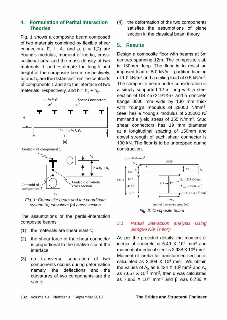
132 Volume 43 Number 3 September 2013 The Bridge and Structural Engineer
(4) the deformation of the two components satisfies the assumptions of planesection in the classical beam theory.
5. ResultsDesignacompositefloorwithbeamsat3mcentres spanning 12m. The composite slab is 130mm deep. The floor is to resist animposed load of 5.0 kN/m2, partition loading of 1.0 kN/m2 and a ceiling load of 0.5 kN/m2. The composite beam under consideration is a simply supported 12-m long with a steel section of UB 457X191X67 and a concrete flange 3000 mm wide by 130 mm thickwith Young’s modulus of 28000 N/mm2.Steel has a Young’s modulus of 205000 N/mm2and a yield stress of 355 N/mm2. Stud shear connectors has 19 mm diameter at a longitudinal spacing of 150mm and dowel strength of each shear connector is 100kN.Theflooristobeunproppedduringconstruction.
Fig. 2: Composite beam
5.1 Partial interaction analysis Using Jianguo Nie Theory
As per the provided details, the moment of inertia of concrete is 5.49 X 108 mm4 and moment of inertia of steel is 2.938 X 108 mm4. Moment of inertia for transformed section is calculated as 3.304 X 108 mm4. We obtain the values of A0 as 6.434 X 103 mm2 and A1 as 7.657 X 10⁻⁶ mm-2,thenαwascalculatedas 7.855 X 10⁻⁴ mm-1 and β was 6.736 X
4. Formulation of Parital Interaction Theories
Fig. 1 shows a composite beam composed oftwomaterialscombinedbyflexibleshearconnectors. Ei, Ii, Ai, and ρi (i = 1,2) are Young’s modulus, moment of inertia, cross-sectional area and the mass density of two materials. L and H denote the length and height of the composite beam, respectively. h1 and h2 are the distances from the centroids of components 1 and 2 to the interface of two materials, respectively, and h = h1 + h2.
Fig. 1: Composite beam and the coordinate system (a) elevation; (b) cross section
The assumptions of the partial-interaction composite beams
(1) the materials are linear elastic;
(2) the shear force of the shear connector is proportional to the relative slip at the interface;
(3) no transverse separation of two components occurs during deformation namely, the deflections and thecurvatures of two components are the same;
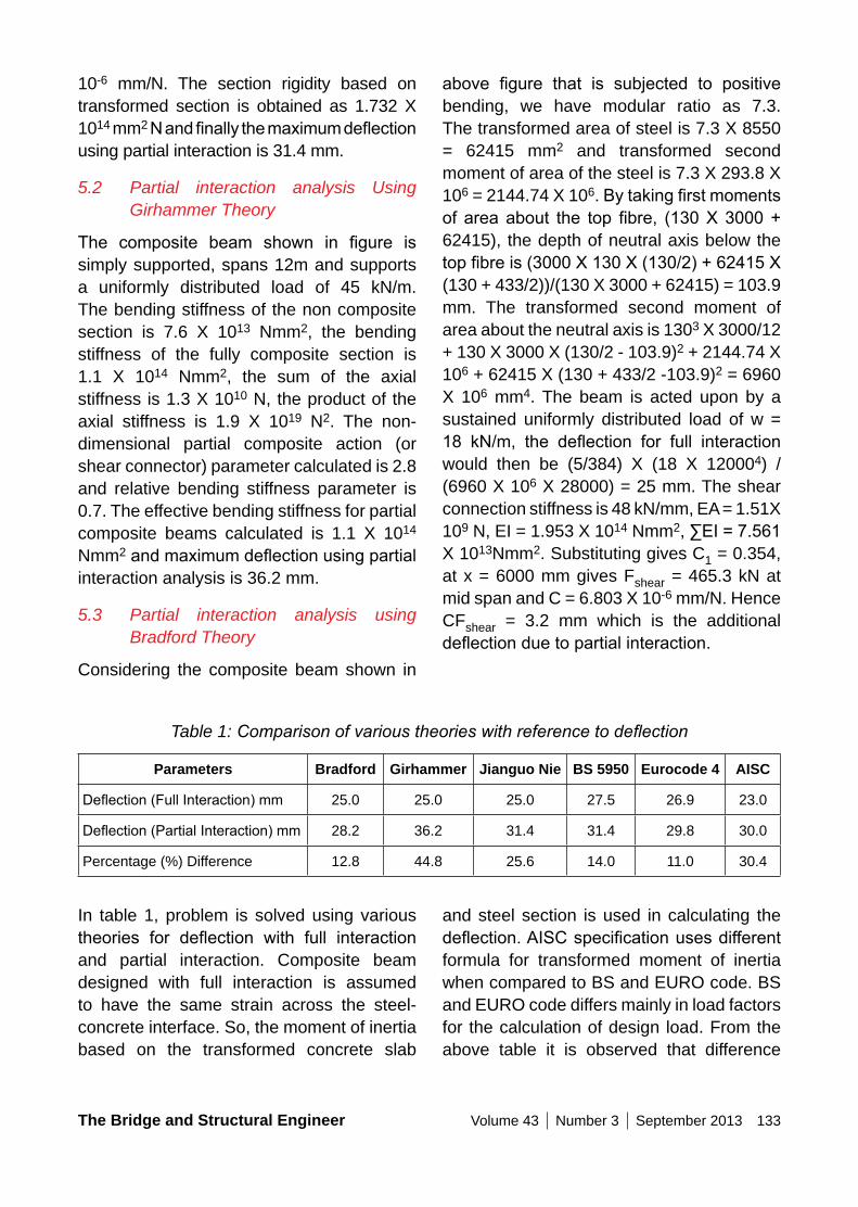
The Bridge and Structural Engineer Volume 43 Number 3 September 2013 133
above figure that is subjected to positivebending, we have modular ratio as 7.3. The transformed area of steel is 7.3 X 8550 = 62415 mm2 and transformed second moment of area of the steel is 7.3 X 293.8 X 106 = 2144.74 X 106.Bytakingfirstmomentsof areaabout the top fibre, (130X3000+62415), the depth of neutral axis below the topfibreis(3000X130X(130/2)+62415X(130 + 433/2))/(130 X 3000 + 62415) = 103.9 mm. The transformed second moment of area about the neutral axis is 1303 X 3000/12 + 130 X 3000 X (130/2 - 103.9)2 + 2144.74 X 106 + 62415 X (130 + 433/2 -103.9)2 = 6960 X 106 mm4. The beam is acted upon by a sustained uniformly distributed load of w = 18 kN/m, the deflection for full interactionwould then be (5/384) X (18 X 120004) / (6960 X 106 X 28000) = 25 mm. The shear connection stiffness is 48 kN/mm, EA = 1.51X 10⁹ N, EI = 1.953 X 10¹⁴ Nmm2,∑EI=7.561X 10¹³Nmm2. Substituting gives C1 = 0.354, at x = 6000 mm gives Fshear = 465.3 kN at mid span and C = 6.803 X 10⁻⁶ mm/N. Hence CFshear = 3.2 mm which is the additional deflectionduetopartialinteraction.
10-6 mm/N. The section rigidity based on transformed section is obtained as 1.732 X 1014 mm2Nandfinallythemaximumdeflectionusing partial interaction is 31.4 mm.
5.2 Partial interaction analysis Using Girhammer Theory
The composite beam shown in figure issimply supported, spans 12m and supports a uniformly distributed load of 45 kN/m. The bending stiffness of the non composite section is 7.6 X 10¹³ Nmm2, the bending stiffness of the fully composite section is 1.1 X 10¹⁴ Nmm2, the sum of the axial stiffness is 1.3 X 10¹⁰ N, the product of the axial stiffness is 1.9 X 10¹⁹ N2. The non-dimensional partial composite action (or shear connector) parameter calculated is 2.8 and relative bending stiffness parameter is 0.7. The effective bending stiffness for partial composite beams calculated is 1.1 X 10¹⁴ Nmm2andmaximumdeflectionusingpartialinteraction analysis is 36.2 mm.
5.3 Partial interaction analysis using Bradford Theory
Considering the composite beam shown in
Table 1: Comparison of various theories with reference to deflection
Parameters Bradford Girhammer Jianguo nie BS 5950 Eurocode 4 AISC
Deflection(FullInteraction)mm 25.0 25.0 25.0 27.5 26.9 23.0
Deflection(PartialInteraction)mm 28.2 36.2 31.4 31.4 29.8 30.0
Percentage (%) Difference 12.8 44.8 25.6 14.0 11.0 30.4
In table 1, problem is solved using various theories for deflection with full interactionand partial interaction. Composite beam designed with full interaction is assumed to have the same strain across the steel-concrete interface. So, the moment of inertia based on the transformed concrete slab
and steel section is used in calculating the deflection.AISCspecificationusesdifferentformula for transformed moment of inertia when compared to BS and EURO code. BS and EURO code differs mainly in load factors for the calculation of design load. From the above table it is observed that difference
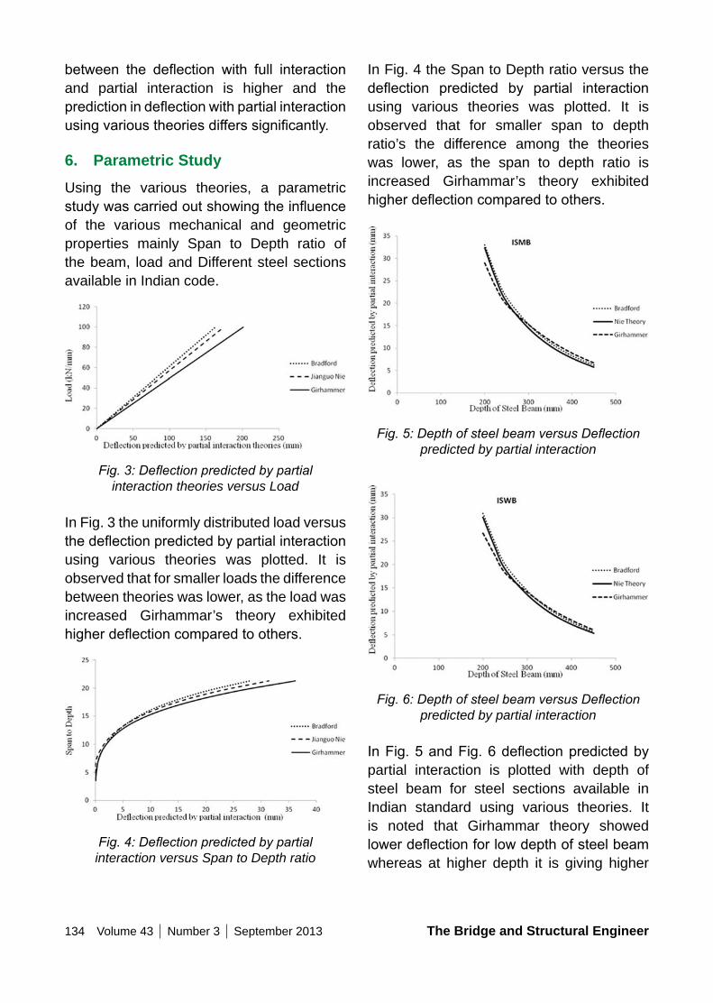
134 Volume 43 Number 3 September 2013 The Bridge and Structural Engineer
In Fig. 4 the Span to Depth ratio versus the deflection predicted by partial interactionusing various theories was plotted. It is observed that for smaller span to depth ratio’s the difference among the theories was lower, as the span to depth ratio is increased Girhammar’s theory exhibited higherdeflectioncomparedtoothers.
Fig. 5: Depth of steel beam versus Deflection predicted by partial interaction
Fig. 6: Depth of steel beam versus Deflection predicted by partial interaction
InFig.5andFig.6deflectionpredictedbypartial interaction is plotted with depth of steel beam for steel sections available in Indian standard using various theories. It is noted that Girhammar theory showed lowerdeflectionforlowdepthofsteelbeamwhereas at higher depth it is giving higher
between the deflection with full interactionand partial interaction is higher and the predictionindeflectionwithpartialinteractionusingvarioustheoriesdifferssignificantly.
6. Parametric StudyUsing the various theories, a parametric studywascarriedoutshowingtheinfluenceof the various mechanical and geometric properties mainly Span to Depth ratio of the beam, load and Different steel sections available in Indian code.
Fig. 3: Deflection predicted by partial interaction theories versus Load
In Fig. 3 the uniformly distributed load versus thedeflectionpredictedbypartialinteractionusing various theories was plotted. It is observed that for smaller loads the difference between theories was lower, as the load was increased Girhammar’s theory exhibited higherdeflectioncomparedtoothers.
Fig. 4: Deflection predicted by partial interaction versus Span to Depth ratio
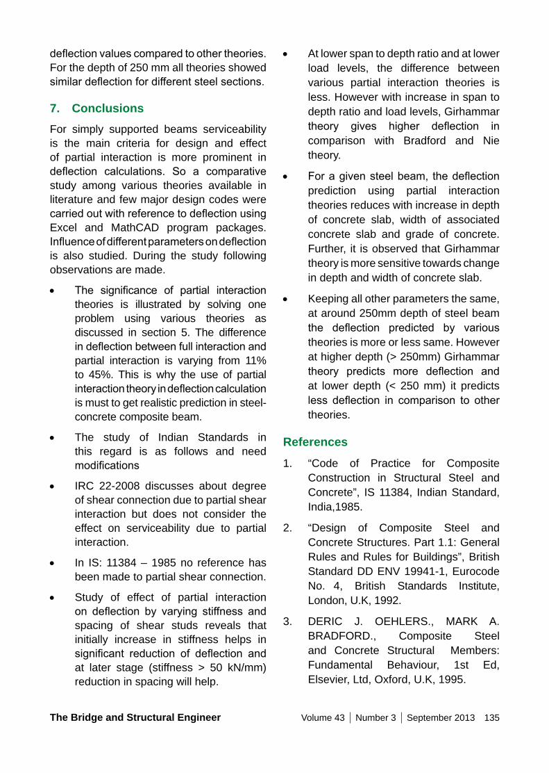
The Bridge and Structural Engineer Volume 43 Number 3 September 2013 135
• At lower span to depth ratio and at lower load levels, the difference between various partial interaction theories is less. However with increase in span to depth ratio and load levels, Girhammar theory gives higher deflection incomparison with Bradford and Nie theory.
• Foragivensteelbeam, thedeflectionprediction using partial interaction theories reduces with increase in depth of concrete slab, width of associated concrete slab and grade of concrete. Further, it is observed that Girhammar theory is more sensitive towards change in depth and width of concrete slab.
• Keeping all other parameters the same, at around 250mm depth of steel beam the deflection predicted by varioustheories is more or less same. However at higher depth (> 250mm) Girhammar theory predicts more deflection andat lower depth (< 250 mm) it predicts less deflection in comparison to othertheories.
References
1. “Code of Practice for Composite Construction in Structural Steel and Concrete”, IS 11384, Indian Standard, India,1985.
2. “Design of Composite Steel and Concrete Structures. Part 1.1: General Rules and Rules for Buildings”, British Standard DD ENV 1994 1-1, Eurocode No. 4, British Standards Institute, London, U.K, 1992.
3. DERIC J. OEHLERS., MARK A. BRADFORD., Composite Steel and Concrete Structural Members: Fundamental Behaviour, 1st Ed, Elsevier, Ltd, Oxford, U.K, 1995.
deflectionvaluescomparedtoothertheories.For the depth of 250 mm all theories showed similardeflectionfordifferentsteelsections.
7. ConclusionsFor simply supported beams serviceability is the main criteria for design and effect of partial interaction is more prominent in deflection calculations. So a comparativestudy among various theories available in literature and few major design codes were carriedoutwithreferencetodeflectionusingExcel and MathCAD program packages. Influenceofdifferentparametersondeflectionis also studied. During the study following observations are made.
• The significance of partial interactiontheories is illustrated by solving one problem using various theories as discussed in section 5. The difference indeflectionbetweenfullinteractionandpartial interaction is varying from 11% to 45%. This is why the use of partial interactiontheoryindeflectioncalculationis must to get realistic prediction in steel-concrete composite beam.
• The study of Indian Standards in this regard is as follows and need modifications
• IRC 22-2008 discusses about degree of shear connection due to partial shear interaction but does not consider the effect on serviceability due to partial interaction.
• In IS: 11384 – 1985 no reference has been made to partial shear connection.
• Study of effect of partial interaction on deflection by varying stiffness andspacing of shear studs reveals that initially increase in stiffness helps in significant reduction of deflection andat later stage (stiffness > 50 kN/mm) reduction in spacing will help.
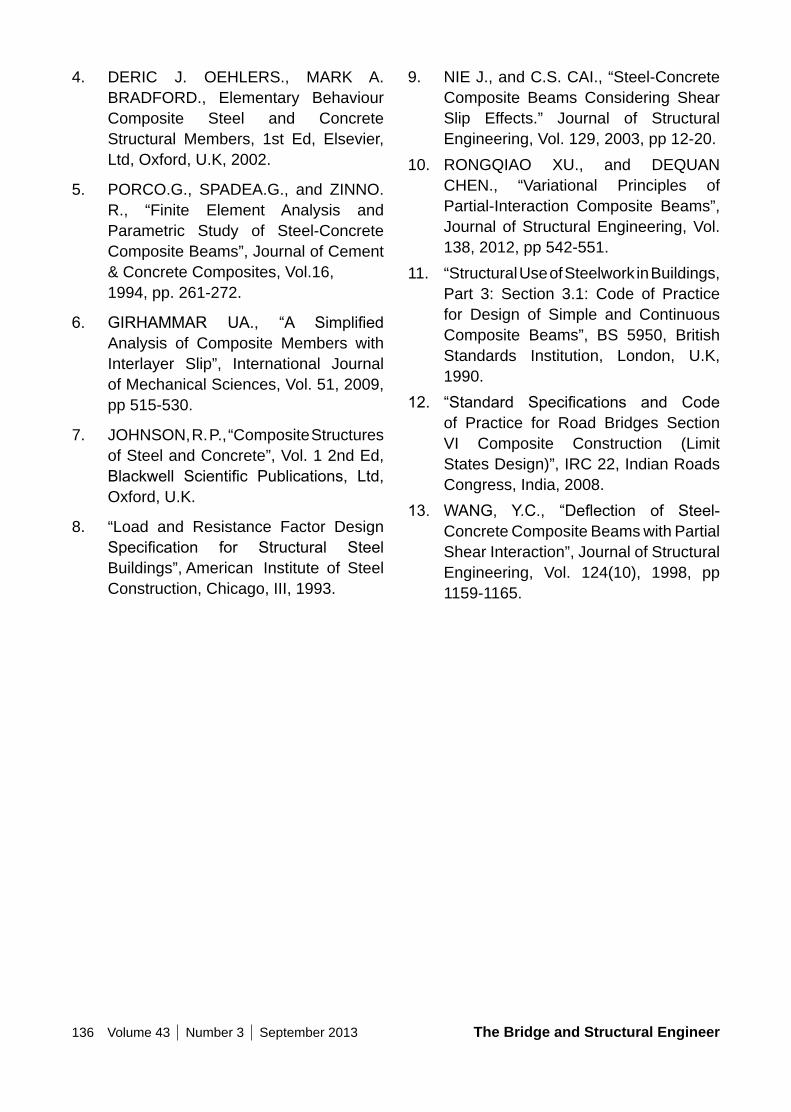
136 Volume 43 Number 3 September 2013 The Bridge and Structural Engineer
9. NIE J., and C.S. CAI., “Steel-Concrete Composite Beams Considering Shear Slip Effects.” Journal of Structural Engineering, Vol. 129, 2003, pp 12-20.
10. RONGQIAO XU., and DEQUAN CHEN., “Variational Principles of Partial-Interaction Composite Beams”, Journal of Structural Engineering, Vol. 138, 2012, pp 542-551.
11. “Structural Use of Steelwork in Buildings, Part 3: Section 3.1: Code of Practice for Design of Simple and Continuous Composite Beams”, BS 5950, British Standards Institution, London, U.K, 1990.
12. “Standard Specifications and Codeof Practice for Road Bridges Section VI Composite Construction (Limit States Design)”, IRC 22, Indian Roads Congress, India, 2008.
13. WANG, Y.C., “Deflection of Steel-Concrete Composite Beams with Partial Shear Interaction”, Journal of Structural Engineering, Vol. 124(10), 1998, pp 1159-1165.
4. DERIC J. OEHLERS., MARK A. BRADFORD., Elementary Behaviour Composite Steel and Concrete Structural Members, 1st Ed, Elsevier, Ltd, Oxford, U.K, 2002.
5. PORCO.G., SPADEA.G., and ZINNO. R., “Finite Element Analysis and Parametric Study of Steel-Concrete Composite Beams”, Journal of Cement & Concrete Composites, Vol.16, 1994, pp. 261-272.
6. GIRHAMMAR UA., “A SimplifiedAnalysis of Composite Members with Interlayer Slip”, International Journal of Mechanical Sciences, Vol. 51, 2009, pp 515-530.
7. JOHNSON, R. P., “Composite Structures of Steel and Concrete”, Vol. 1 2nd Ed, Blackwell Scientific Publications, Ltd,Oxford, U.K.
8. “Load and Resistance Factor Design Specification for Structural SteelBuildings”, American Institute of Steel Construction, Chicago, III, 1993.
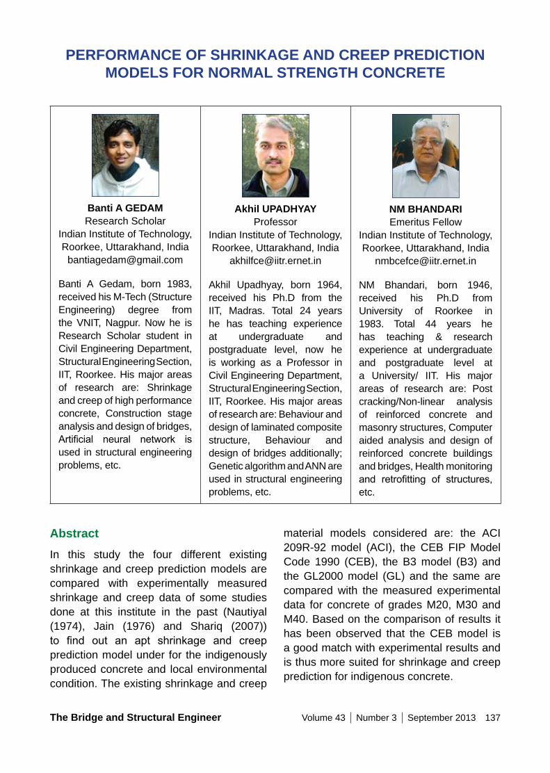
The Bridge and Structural Engineer Volume 43 Number 3 September 2013 137
Banti A GEDAM Research Scholar
Indian Institute of Technology, Roorkee, Uttarakhand, India
Banti A Gedam, born 1983, received his M-Tech (Structure Engineering) degree from the VNIT, Nagpur. Now he is Research Scholar student in Civil Engineering Department, Structural Engineering Section, IIT, Roorkee. His major areas of research are: Shrinkage and creep of high performance concrete, Construction stage analysis and design of bridges, Artificial neural network isused in structural engineering problems, etc.
Akhil UPADHyAy Professor
Indian Institute of Technology, Roorkee, Uttarakhand, India
Akhil Upadhyay, born 1964, received his Ph.D from the IIT, Madras. Total 24 years he has teaching experience at undergraduate and postgraduate level, now he is working as a Professor in Civil Engineering Department, Structural Engineering Section, IIT, Roorkee. His major areas of research are: Behaviour and design of laminated composite structure, Behaviour and design of bridges additionally; Genetic algorithm and ANN are used in structural engineering problems, etc.
nM BHAnDARI Emeritus Fellow
Indian Institute of Technology, Roorkee, Uttarakhand, India
NM Bhandari, born 1946, received his Ph.D from University of Roorkee in 1983. Total 44 years he has teaching & research experience at undergraduate and postgraduate level at a University/ IIT. His major areas of research are: Post cracking/Non-linear analysis of reinforced concrete and masonry structures, Computer aided analysis and design of reinforced concrete buildings and bridges, Health monitoring and retrofitting of structures,etc.
PERFoRMAnCE oF SHRInKAGE AnD CREEP PREDICTIon MoDELS FoR noRMAL STREnGTH ConCRETE
AbstractIn this study the four different existing shrinkage and creep prediction models are compared with experimentally measured shrinkage and creep data of some studies done at this institute in the past (Nautiyal (1974), Jain (1976) and Shariq (2007)) to find out an apt shrinkage and creepprediction model under for the indigenously produced concrete and local environmental condition. The existing shrinkage and creep
material models considered are: the ACI 209R-92 model (ACI), the CEB FIP Model Code 1990 (CEB), the B3 model (B3) and the GL2000 model (GL) and the same are compared with the measured experimental data for concrete of grades M20, M30 and M40. Based on the comparison of results it has been observed that the CEB model is a good match with experimental results and is thus more suited for shrinkage and creep prediction for indigenous concrete.
138 Volume 43 Number 3 September 2013 The Bridge and Structural Engineer
concrete do not predict the material properties of HPC satisfactorily. Mazloom et al. (2004) compared shrinkage and creep results with ACI and CEB model and observed that both the models underestimate the shrinkage strain at early age and at later age the CEB and ACI models underestimate and overestimate total shrinkage respectively. Still further both models overestimate creep strain. Akthem et al. (2005) studied the performance of existing shrinkage and creep prediction evaluation models with the help of RILEM Data Bank of shrinkage and creepusingfivedifferentstatisticalmethodstodeterminewhichmodelisbetter.Thefivedifferent statistical evaluation methods used were: residual method, B3 coefficient ofvariationmethod,CEBcoefficientofvariationmethod, CEB mean square error method and CEB mean deviation method and observed that the B3 and GL 2000 models are good for shrinkage strain prediction while CEB, B3 and GL 2000 models are good for creep strain prediction. Brook (2005) has reported 30 year shrinkage and creep measured data having different water/cement ratio of concrete and the results were compared with fiveshrinkageandcreeppredictionmodeli.e.CEB, Gardner, Bazant and Baweja, ACI and BS 8110 and observed that most prediction models failed to recognize the influence ofstrength of concrete and type of aggregate oncreepcoefficient.Goeletal.(2007)usedexperimental measured data of Russell and Larson (1989) and compared with the fiveexistingshrinkageandcreeppredictionmodels i.e. the ACI model, the CEB Model, the B3 model, the Muller model and the GL model. Based on comparison authors concluded that the GL model performed best for prediction of shrinkage and creep of concrete. Karthikeyan et al. (2008) found CEB model suitable for shrinkage and creep prediction for HPC prepared in Indian environment. It was observed that at
Keywords: creep; shrinkage; compressive strength; modulus of elasticity; prediction model.
1. IntroductionLong term behaviour of concrete structures is mainly affected due to secondary effects of creep and shrinkage. It has been observed that the concrete infrastructures built in last 2-3 decade have shown unacceptable excessive deflection, cracking and distressin early life due to lack of understanding of time dependent concrete material properties. In India most of infrastructure built in last 1-2 decades have been designed and constructed by normal grade concrete and in presence of sustained load the shrinkage andcreepofconcretesignificantlyaffectitslong term behaviour. Therefore, the study of shrinkage and creep of normal concrete under the local construction and environment condition is important to ensure that the structure remain serviceable and durable, all through its anticipated life.
There are many intrinsic and extrinsic factors which affect the shrinkage and creep phenomenon of concrete. These factors are: mix proportion i.e. ratio of cement, sand, aggregate, admixture and w/c ratio if any; effect of environmental factors like temperature and humidity. Gardener and Lockman(2001)havedescribedthemodifiedand updated GL model and explained design procedure to estimate shrinkage and creep for normal-strength concretes, which is defined as concretes with meancompressive strength less than 82 MPa. Huo et al. (2001) reported detailed experimental program to study material properties like creep, shrinkage and modulus of elasticity of HPC made with local materials from Nebraska and compared the results with ACI model and observed that the ACI equation for shrinkage, creep and elastic modulus of
The Bridge and Structural Engineer Volume 43 Number 3 September 2013 139
c : cement contain in concrete (kg/m3)
d : constant, 10 days for standard condition and 6 to 30 days for other than standard condition
Ecm : modulus of elasticity of concrete at the time of days (MPa)
Eci : modulus of elasticity of concrete at the time of initial load (MPa)
f : constant, depends on type of curing, 7 days for moist cured concrete and 1-3 days for steam cured concrete under the standard condition for other than standard condition 20 to 130 days
fcm : mean compressive strength of concrete at the age of t0 days (MPa)
h : relative humidity of the ambient environment, decimal
J(t, t0) : creep strain in microstrains per unit MPa
k : correction factor depends on type of cement
kh : factor depends on relative humidity
ks : shape factor depends on cross section
RH : relative humidity of the ambient environment, percentage
t : age of concrete at the time of observation (days)
t0 : age of concrete at the time of loading (days)
later stage maturity 500 days the difference between experimental and CEB prediction is increasing. Pan et al. (2013) evaluated the existing CEB model with three different statistical methods i.e. the residual method, B3 coefficient of variation method andCEB coefficient of variation method usingextensive compiled database. Based on the statistical evaluation of result the CEB model ismodified for local condition andmaterialproperties and reported that the modifiedCEB model is better prediction model, especially for HPC concrete.
As seen in literature review, the shrinkage and creep prediction model for normal strength concrete gets affected by local construction material and environment condition. Not much work has been reported for shrinkage and creep in indigenous normal strength concrete. Therefore, in the present study the four existing popular material shrinkage and creep prediction models are studied to determine which model predicts shrinkage and creep behaviour of normal grade of concrete satisfactorily, under the local environmental condition.
1.1 Notation
The following symbols are used in this paper:
Ac : cross-section area (mm2)
a, b : factor depends on type of cement
Cd (t, to, ts)
: additional compliance function due to simultaneous drying
Co (t, to) : compliance function for basic creep (creep at constant moisture content and no moisture movement through the material)
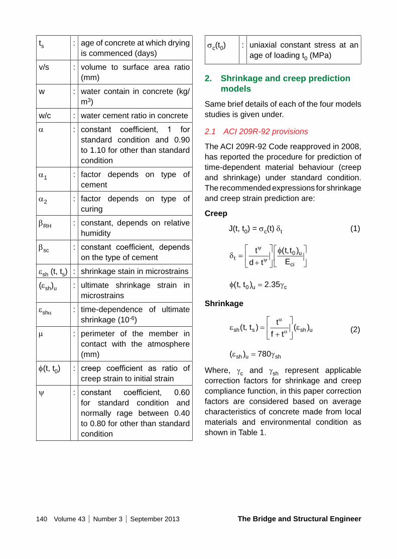
140 Volume 43 Number 3 September 2013 The Bridge and Structural Engineer
sc(t0) : uniaxial constant stress at an age of loading t0 (MPa)
2. Shrinkage and creep prediction models
Same brief details of each of the four models studies is given under.
2.1 ACI 209R-92 provisions
The ACI 209R-92 Code reapproved in 2008, has reported the procedure for prediction of time-dependent material behaviour (creep and shrinkage) under standard condition. The recommended expressions for shrinkage and creep strain prediction are:
Creep
J(t, t0) = sc(t) δt (1)
δ
fy
ytu
ci
t
d t
t t
E=
+
( , )0
f g( , ) .t t u c0 2 35=
Shrinkage
e ea
ash s sh ut tt
f t( , ) ( )=
+
(2)
( )e gsh u sh= 780
Where, gc and gsh represent applicable correction factors for shrinkage and creep compliance function, in this paper correction factors are considered based on average characteristics of concrete made from local materials and environmental condition as shown in Table 1.
ts : age of concrete at which drying is commenced (days)
v/s : volume to surface area ratio (mm)
w : water contain in concrete (kg/m3)
w/c : water cement ratio in concrete
a : constant coefficient, 1 forstandard condition and 0.90 to 1.10 for other than standard condition
a1 : factor depends on type of cement
a2 : factor depends on type of curing
bRH : constant, depends on relative humidity
bsc : constant coefficient, dependson the type of cement
esh (t, ts) : shrinkage stain in microstrains
(esh)u : ultimate shrinkage strain in microstrains
esha : time-dependence of ultimate shrinkage (10-6)
m : perimeter of the member in contact with the atmosphere (mm)
f(t, t0) : creep coefficient as ratio ofcreep strain to initial strain
y : constant coefficient, 0.60for standard condition and normally rage between 0.40 to 0.80 for other than standard condition
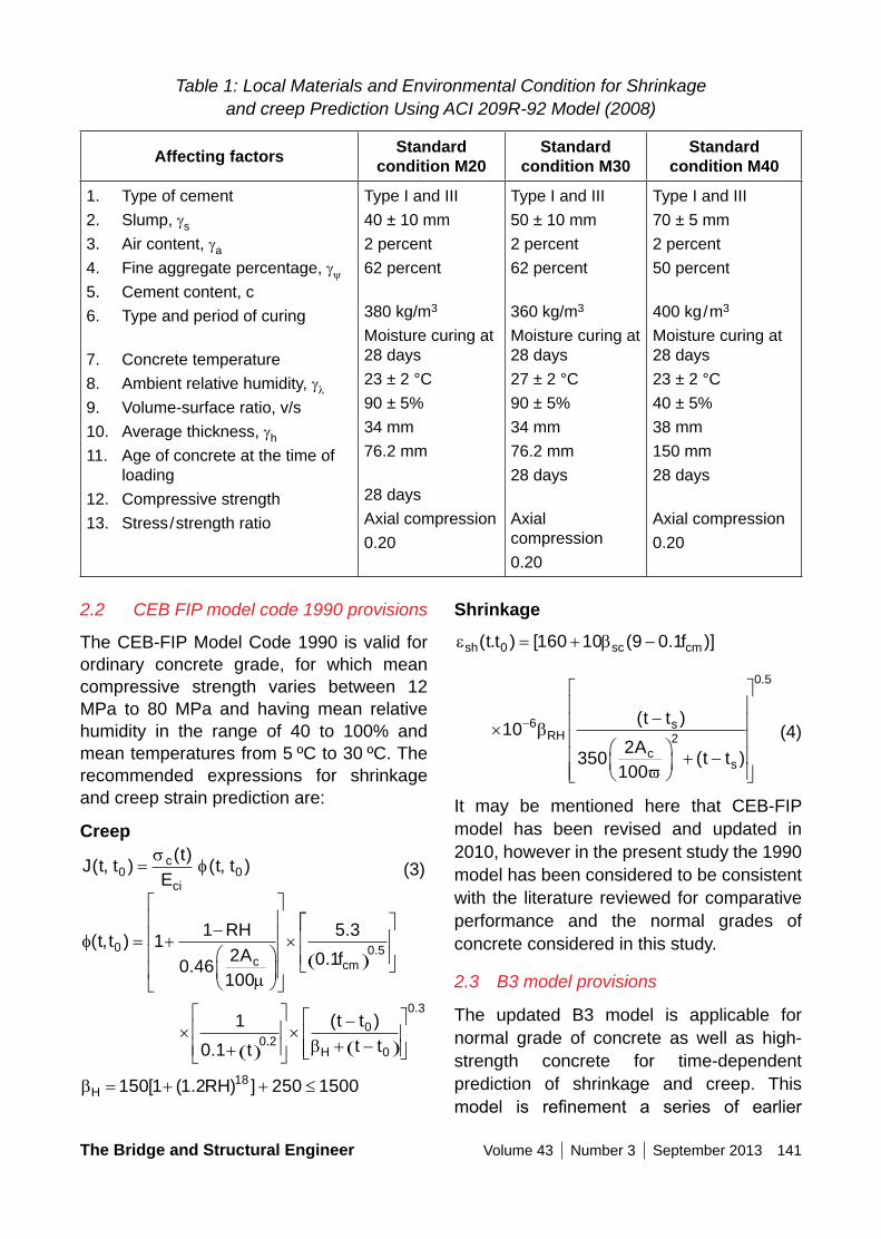
The Bridge and Structural Engineer Volume 43 Number 3 September 2013 141
Table 1: Local Materials and Environmental Condition for Shrinkage and creep Prediction Using ACI 209R-92 Model (2008)
Affecting factors Standard condition M20
Standard condition M30
Standard condition M40
1. Type of cement2. Slump, gs
3. Air content, ga
4. Fine aggregate percentage, gy
5. Cement content, c6. Type and period of curing
7. Concrete temperature8. Ambient relative humidity, gl
9. Volume-surface ratio, v/s10. Average thickness, gh
11. Age of concrete at the time of loading
12. Compressive strength13. Stress/strength ratio
Type I and III40 ± 10 mm2 percent62 percent
380 kg/m3
Moisture curing at 28 days23 ± 2 °C90 ± 5%34 mm76.2 mm
28 daysAxial compression0.20
Type I and III50 ± 10 mm2 percent62 percent
360 kg/m3
Moisture curing at 28 days27 ± 2 °C90 ± 5%34 mm76.2 mm28 days
Axial compression0.20
Type I and III70 ± 5 mm2 percent50 percent
400 kg/m3
Moisture curing at 28 days23 ± 2 °C40 ± 5%38 mm150 mm28 days
Axial compression0.20
Shrinkage
e bsh sc cmt t f( . ) [ ( . )]0 160 10 9 0 1= + −
×−
+ −
−10
3502
100
62
0 5
b
ϖ
RHs
cs
t t
At t
( )
( )
.
(4)
It may be mentioned here that CEB-FIP model has been revised and updated in 2010, however in the present study the 1990 model has been considered to be consistent with the literature reviewed for comparative performance and the normal grades of concrete considered in this study.
2.3 B3 model provisions
The updated B3 model is applicable for normal grade of concrete as well as high-strength concrete for time-dependent prediction of shrinkage and creep. This model is refinement a series of earlier
2.2 CEB FIP model code 1990 provisions
The CEB-FIP Model Code 1990 is valid for ordinary concrete grade, for which mean compressive strength varies between 12 MPa to 80 MPa and having mean relative humidity in the range of 40 to 100% and mean temperatures from 5 ºC to 30 ºC. The recommended expressions for shrinkage and creep strain prediction are:
Creep
J t tt
Et tc
ci
( , )( )
( , )0 0=s
f (3)
f
m
( , )
.
.
..
t tRH
A fc cm
0 0 51
1
0 462
100
5 3
0 1= +
−
×( )
×+ ( )
×−
+ −( )
1
0 10 2
0
0
0 3
.
( ).
.
t
t t
t tHb
bH RH= + + ≤150 1 1 2 250 150018[ ( . ) ]
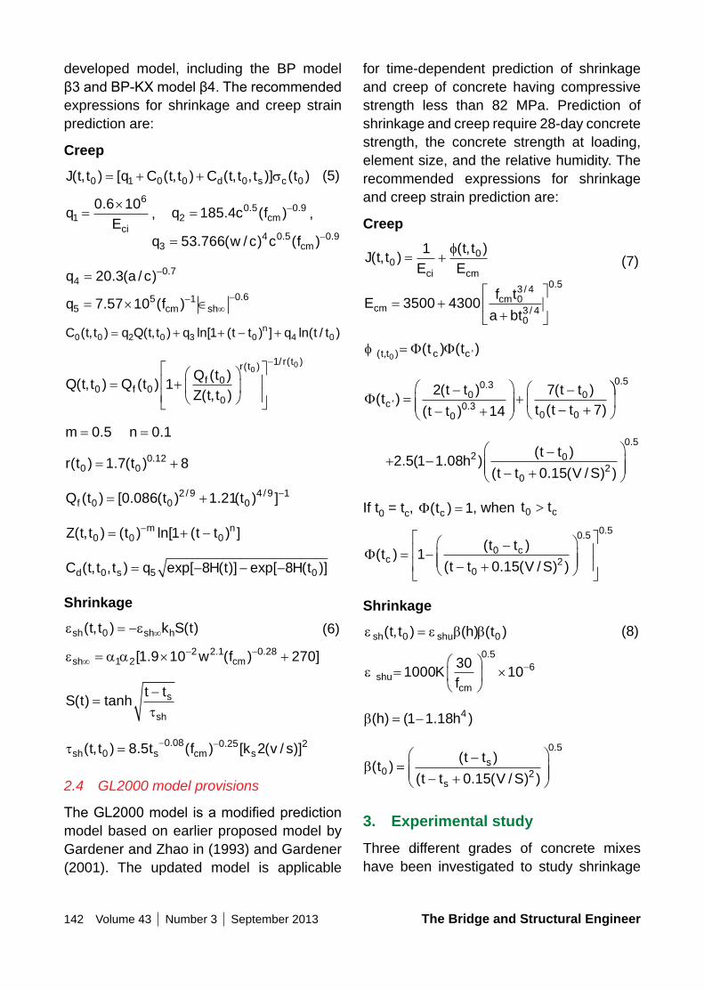
142 Volume 43 Number 3 September 2013 The Bridge and Structural Engineer
for time-dependent prediction of shrinkage and creep of concrete having compressive strength less than 82 MPa. Prediction of shrinkage and creep require 28-day concrete strength, the concrete strength at loading, element size, and the relative humidity. The recommended expressions for shrinkage and creep strain prediction are:
Creep
J t tE
t t
Eci cm
( , )( , )
001
= +f
(7)
Ef t
a btcm
cm= ++
3500 4300 0
3 4
03 4
0 5/
/
.
f ( , ) ’( ) ( )t t c ct t0
= Φ Φ
Φ( )( )
( )
( )
( )’
.
.t
t t
t t
t t
t t tc =−
− +
+
−− +
2
14
7
70
0 3
00 3
0
0 0
0 5.
+ −−
− +
2 5 1 1 08
0 152 0
02
0 5
. ( . )( )
( . ( / ) )
.
ht t
t t V S
If t0 = tc, Φ( )tc = 1, when t tc0 >
Φ( )( )
( . ( / ) )
. .
tt t
t t V Sc
c= −−
− +
10 150
02
0 5 0 5
Shrinkage
e e b bsh shut t h t( , ) ( ) ( )0 0= (8)
e shucm
Kf
=
× −1000
3010
0 56
.
b( ) ( . )h h= −1 1 18 4
b( )( )
( . ( / ) )
.
tt t
t t V Ss
s0 2
0 5
0 15=
−− +
3. Experimental studyThree different grades of concrete mixes have been investigated to study shrinkage
developed model, including the BP model β3andBP-KXmodelβ4.Therecommendedexpressions for shrinkage and creep strain prediction are:
Creep
J t t q C t t C t t t td s c( , ) [ ( , ) ( , , )] ( )0 1 0 0 0 0= + + s (5)
qEci
1
60 6 10=
×., q c fcm2
0 5 0 9185 4= −. ( ). . ,
q w c c fcm34 0 5 0 953 766= −. ( / ) ( ). .
q a c40 720 3= −. ( / ) .
q fcm sh55 1 0 6
7 57 10= × ∈−∞
−. ( )
.
C t t q Q t t q t t q t tn0 0 2 0 3 0 4 01( , ) ( , ) ln[ ( ) ] ln( / )= + + − +
Q t t Q tQ t
Z t tff
r t r t
( , ) ( )( )
( , )
( ) / ( )
0 00
0
1
10
0
= +
−
m = 0 5. n = 0 1.
r t t( ) . ( ) .0 0
0 121 7 8= +
Q t t tf ( ) [ . ( ) . ( ) ]/ /0 0
2 90
4 9 10 086 1 21= + −
Z t t t t tm n( , ) ( ) ln[ ( ) ]0 0 01= + −−
C t t t q H t H td s( , , ) exp[ ( )] exp[ ( )]0 5 08 8= − − −
Shrinkage
e esh sh ht t k S t( , ) ( )0 = − ∞ (6)
e a ash cmw f∞− −= × +1 22 2 1 0 281 9 10 270[ . ( ) ]. .
S tt ts
sh
( ) tanh=−τ
τsh s cm st t t f k v s( , ) . ( ) [ ( / )]. .0
0 08 0 25 28 5 2= − −
2.4 GL2000 model provisions
TheGL2000modelisamodifiedpredictionmodel based on earlier proposed model by Gardener and Zhao in (1993) and Gardener (2001). The updated model is applicable
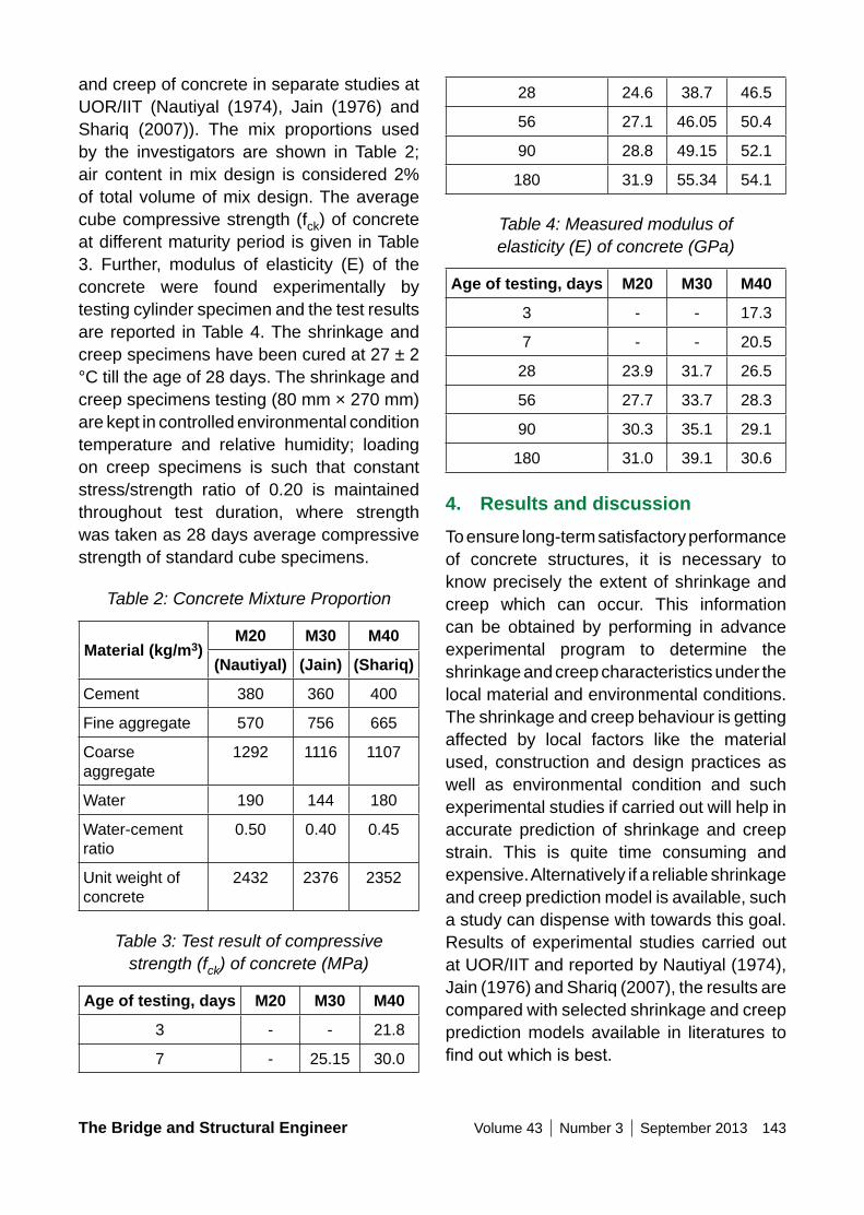
The Bridge and Structural Engineer Volume 43 Number 3 September 2013 143
28 24.6 38.7 46.5
56 27.1 46.05 50.4
90 28.8 49.15 52.1
180 31.9 55.34 54.1
Table 4: Measured modulus of elasticity (E) of concrete (GPa)
Age of testing, days M20 M30 M40
3 - - 17.3
7 - - 20.5
28 23.9 31.7 26.5
56 27.7 33.7 28.3
90 30.3 35.1 29.1
180 31.0 39.1 30.6
4. Results and discussionTo ensure long-term satisfactory performance of concrete structures, it is necessary to know precisely the extent of shrinkage and creep which can occur. This information can be obtained by performing in advance experimental program to determine the shrinkage and creep characteristics under the local material and environmental conditions. The shrinkage and creep behaviour is getting affected by local factors like the material used, construction and design practices as well as environmental condition and such experimental studies if carried out will help in accurate prediction of shrinkage and creep strain. This is quite time consuming and expensive. Alternatively if a reliable shrinkage and creep prediction model is available, such a study can dispense with towards this goal. Results of experimental studies carried out at UOR/IIT and reported by Nautiyal (1974), Jain (1976) and Shariq (2007), the results are compared with selected shrinkage and creep prediction models available in literatures to findoutwhichisbest.
and creep of concrete in separate studies at UOR/IIT (Nautiyal (1974), Jain (1976) and Shariq (2007)). The mix proportions used by the investigators are shown in Table 2; air content in mix design is considered 2% of total volume of mix design. The average cube compressive strength (fck) of concrete at different maturity period is given in Table 3. Further, modulus of elasticity (E) of the concrete were found experimentally by testing cylinder specimen and the test results are reported in Table 4. The shrinkage and creep specimens have been cured at 27 ± 2 °C till the age of 28 days. The shrinkage and creep specimens testing (80 mm × 270 mm) are kept in controlled environmental condition temperature and relative humidity; loading on creep specimens is such that constant stress/strength ratio of 0.20 is maintained throughout test duration, where strength was taken as 28 days average compressive strength of standard cube specimens.
Table 2: Concrete Mixture Proportion
Material (kg/m3)M20 M30 M40
(nautiyal) (Jain) (Shariq)
Cement 380 360 400
Fine aggregate 570 756 665
Coarse aggregate
1292 1116 1107
Water 190 144 180
Water-cement ratio
0.50 0.40 0.45
Unit weight of concrete
2432 2376 2352
Table 3: Test result of compressive strength (fck) of concrete (MPa)
Age of testing, days M20 M30 M40
3 - - 21.8
7 - 25.15 30.0
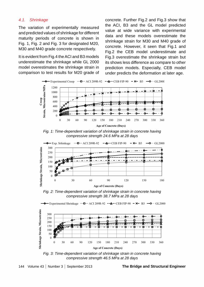
144 Volume 43 Number 3 September 2013 The Bridge and Structural Engineer
concrete. Further Fig.2 and Fig.3 show that the ACI, B3 and the GL model predicted value at wide variance with experimental data and these models overestimate the shrinkage strain for M30 and M40 grade of concrete. However, it seen that Fig.1 and Fig.2 the CEB model underestimate and Fig.3 overestimate the shrinkage strain but its shows less difference as compare to other prediction models. Especially, CEB model under predicts the deformation at later age.
4.1. Shrinkage
The variation of experimentally measured and predicted values of shrinkage for different maturity periods of concrete is shown in Fig. 1, Fig. 2 and Fig. 3 for designated M20, M30 and M40 grade concrete respectively.
It is evident from Fig.4 the ACI and B3 models underestimate the shrinkage while GL 2000 model overestimates the shrinkage strain in comparison to test results for M20 grade of
Fig. 1: Time-dependent variation of shrinkage strain in concrete having compressive strength 24.6 MPa at 28 days
Fig. 2: Time-dependent variation of shrinkage strain in concrete having compressive strength 38.7 MPa at 28 days
Fig. 3: Time-dependent variation of shrinkage strain in concrete having compressive strength 46.5 MPa at 28 days
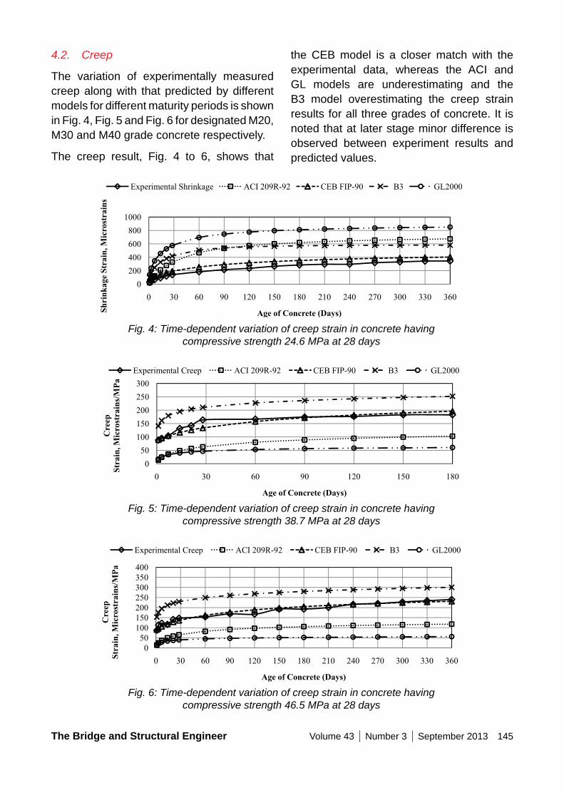
The Bridge and Structural Engineer Volume 43 Number 3 September 2013 145
4.2. Creep
The variation of experimentally measured creep along with that predicted by different models for different maturity periods is shown in Fig. 4, Fig. 5 and Fig. 6 for designated M20, M30 and M40 grade concrete respectively.
The creep result, Fig. 4 to 6, shows that
the CEB model is a closer match with the experimental data, whereas the ACI and GL models are underestimating and the B3 model overestimating the creep strain results for all three grades of concrete. It is noted that at later stage minor difference is observed between experiment results and predicted values.
Fig. 4: Time-dependent variation of creep strain in concrete having compressive strength 24.6 MPa at 28 days
Fig. 5: Time-dependent variation of creep strain in concrete having compressive strength 38.7 MPa at 28 days
Fig. 6: Time-dependent variation of creep strain in concrete having compressive strength 46.5 MPa at 28 days
146 Volume 43 Number 3 September 2013 The Bridge and Structural Engineer
5. ConclusionThe shrinkage and creep of concrete has major impact in prediction of long-term behaviour of concrete structure. In this regard, the available experimental results of normal grade concrete are compared with four common shrinkage and creep models (the ACI 209R-92 model, the CEB FIP Model Code 1990, the B3 model and the GL2000 model) and based on the comparison following conclusion are drawn:
1. The comparatively study of the results show that the CEB model is good for satisfactory prediction of shrinkage and creep for normal strength concrete under local condition. Also, this model shows goodness of fit with Nautiyal(1974), Jain (1976) and Shariq (2007) reported experimental data while for other prediction models shows large difference.
2. The ACI, GL and B3 model give large shrinkage and creep strain prediction error and hence not suitable under Indian Environmental condition.
References1. ACI 209., Prediction of Creep, Shrinkage
and Temperature Effects in Concrete Structures, ACI Special Publication, 2008 .
2. AL-MANASEER, A. A., BAZANT, Z. P., BROOKS, J. J., BURG, R. G., CARREIRA, D. J., CHIORINO, M. A., DAYE, M. A., DILGER, W. H., GARDNER, N. J. & HANSEN, W. “Report on Factors Affecting Shrinkage and Creep of Hardened Concrete. Concrete International, 2005, 21.
3. AL-MANASEER, A. AND LAM, J. P. “Static Evaluation of Shrinkage and Creep Models,” ACI Materials Journal, Vol.102, 2005, pp. 170-176.
4. BAZANT Z. P., & BAWEJA S., “Shrinkage and Creep Prediction Model for Analysis and Design of Concrete Structures: Model B3. ACI Special Publications, Vol.194, 2000, pp. 1-84.
5. BROOKS J. J., “30-Year Shrinkage and Creep of Concrete”, Magazine of Concrete Research, Vol. 57, 2005, pp. 545-556.
6. CEB-FIP Model Code., Design of Concrete Structures, CEB-FIP-Model-Code 1990, British Standard Institution, London, UK, 1993.
7. GARDNER N., & LOCKMAN M., “Design Provisions for Drying Shrinkage and Creep of Normal-Strength Concrete” ACI Materials Journal, Vol. 98, 2001.
8. GARDNER N., & ZHAO J. W., “Shrinkage and Creep Revisited”, ACI Materials Journal, Vol. 90, 1993.
9. GOEL R., KUMAR R., & PAUL D. K., “Comparative Study of Various Shrinkage and Creep Prediction Models for Concrete”, Journal of Materials In Civil Engineering, Vol. 19, 2007, pp. 249.
10. HUO, X. S., AL-OMAISHI, N. & TADROS, M. K. (2001). Creep, Shrinkage and Modulus of Elasticity of High-Performance Concrete. ACI Materials Journal, 98.
11. JAIN K.K., A Study of Structural Properties of Concrete With Fly Ash, PhD Thesis, Roorkee, University of Roorkee, 1976.
12. KARTHIKEYAN J., UPADHYAY A., & BHANDARI N. M., “Artificial NeuralNetwork For Predicting Shrinkage and Creep of High Performance Concrete”, Journal of Advanced Concrete Technology, Vol. 6, 2008, pp. 135-142.
The Bridge and Structural Engineer Volume 43 Number 3 September 2013 147
13. NAUTIYAL B. D., Time Dependent Properties of Fly Ash Concrete, PhD Thesis. Roorkee, University of Roorkee, 1974.
14. MAZLOOM M., “Estimating Long-Term Shrinkage and Creep of High-Strength Concrete”, Cement and Concrete Composites, Vol. 30, 2008, pp.316-326.
15. MAZLOOM, M., RAMEZANIANPOUR A., & BROOKS J., “Effect Of Silica Fume on Mechanical Properties of High-Strength Concrete” Cement and
Concrete Composites, Vol. 26, 2004, pp. 347-357.
16. PAN ZUANFENG, LI BING., & LU ZHITAO., “Re-Evaluation of CEB-FIP 90 Prediction Models For Shrinkage and Creep With Experimental Database”, Construction and Building Materials, Vol.38, 2013, pp. 1022-1030.
17. SHARIQ MOHD., Studies in Creep Characteristics of Concrete and Reinforced Concrete. PhD Thesis. Roorkee, Indian Institute of Technology, 2007.
148 Volume 43 Number 3 September 2013 The Bridge and Structural Engineer
About InG - IABSEThe Indian National Group (ING) of the IABSE was set up in May 1957 under the patronage of the Government of India, Ministry of Road Transport and Highways and State Governments, as a non-officiallearned body with the participation of engineers and professional from both the public and private sectors as well as from various research and academic institutions. The Group organizes lectures, conferences, colloquia and workshops on topical subjects and publishes a quarterly technical journal “The Bridge and Structural Engineer.”
About IABSEThe International Association for Bridge and Structural Engineering (IABSE) was founded in 1929. Today, IABSE has about 4,000 members in over 100 countries. The mission of IABSE is to promote the exchange of knowledge and to advance the practice of structural and bridge engineering worldwide in the service of the profession and society. To accomplish the mission, IABSE organises conferences and publishes the quarterly journal “Structural Engineering International” (SEI), as well as reports and other monographs. IABSE also presents annual awards for outstanding achievements in research and practice that advance the profession of structural engineering. IABSE deals with all kinds of structures, materials and aspects of structural engineering.
The Bridge and Structural Engineer Volume 43 Number 3 September 2013 149
150 Volume 43 Number 3 September 2013 The Bridge and Structural Engineer
The Bridge and Structural Engineer Volume 43 Number 3 September 2013 151
152 Volume 43 Number 3 September 2013 The Bridge and Structural Engineer
APCO Infratech Limited is one of the fast evolving mid-size Construction / infrastructure organisation having a turnover of INR 6000 Millions in India through its business verticals of EPC/PPP Highway, Bridges, Commercial /Industrial / Factory/Power Projects, Water Conveyance systems in Irrigation etc.
Future diversification to Aviation, Railways & Metro Rails, Urban Development, Reality, Hospitality and Overseas Projects is intended.
Our recipe is “fast & qualitative delivery to fullest satisfaction of our Client”
We in APCO believe in enhancing potential of our employees to become competitive & still deliver to the International standards.
Head Office: APCO House, B-9 Vibhuti Khand, Gomti Nagar, Lucknow – 226 010 (U.P.) Phone: +91 -522 – 4036111, 2720520, 2720521, Fax : +91 – 522 – 4036100
Corporate Office: Universal Trade Tower, 4th Floor, Sector : 49, Sohna Road Phone : +91 – 124-4417300, Email : [email protected] Website : www.apcoinfra.com
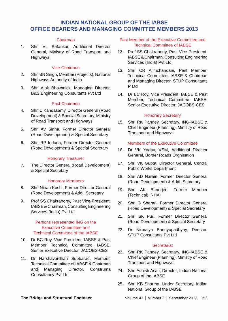
The Bridge and Structural Engineer Volume 43 Number 3 September 2013 153
Past Member of the Executive Committee and Technical Committee of IABSE
12. Prof SS Chakraborty, Past Vice-President, IABSE & Chairman, Consulting Engineering Services (India) Pvt Ltd
13. Shri CR Alimchandani, Past Member, Technical Committee, IABSE & Chairman and Managing Director, STUP Consultants P Ltd
14. Dr BC Roy, Vice President, IABSE & Past Member, Technical Committee, IABSE, Senior Executive Director, JACOBS-CES
Honorary Secretary15. Shri RK Pandey, Secretary, ING-IABSE &
Chief Engineer (Planning), Ministry of Road Transport and Highways
Members of the Executive Committee16. Dr VK Yadav, VSM, Additional Director
General, Border Roads Orgnisation
17. Shri VK Gupta, Director General, Central Public Works Department
18. Shri AD Narain, Former Director General (Road Development) & Addl. Secretary
19. Shri AK Banerjee, Former Member (Technical), NHAI
20. Shri G Sharan, Former Director General (Road Development) & Special Secretary
21. Shri SK Puri, Former Director General (Road Development) & Special Secretary
22. Dr Nirmalya Bandyopadhyay, Director, STUP Consultants Pvt Ltd
Secretariat23. Shri RK Pandey, Secretary, ING-IABSE &
Chief Engineer (Planning), Ministry of Road Transport and Highways
24. Shri Ashish Asati, Director, Indian National Group of the IABSE
25. Shri KB Sharma, Under Secretary, Indian National Group of the IABSE
Chairman1. Shri VL Patankar, Additional Director
General, Ministry of Road Transport and Highways
Vice-Chairmen2. Shri BN Singh, Member (Projects), National
Highways Authority of India
3. Shri Alok Bhowmick, Managing Director, B&S Engineering Consultants Pvt Ltd
Past Chairmen4. Shri C Kandasamy, Director General (Road
Development) & Special Secretary, Ministry of Road Transport and Highways
5. Shri AV Sinha, Former Director General (Road Development) & Special Secretary
6. Shri RP Indoria, Former Director General (Road Development) & Special Secretary
Honorary Treasurer7. The Director General (Road Development)
& Special Secretary
Honorary Members8. Shri Ninan Koshi, Former Director General
(Road Development) & Addl. Secretary
9. Prof SS Chakraborty, Past Vice-President, IABSE & Chairman, Consulting Engineering Services (India) Pvt Ltd
Persons represented ING on the Executive Committee and
Technical Committee of the IABSE10. Dr BC Roy, Vice President, IABSE & Past
Member, Technical Committee, IABSE, Senior Executive Director, JACOBS-CES
11. Dr Harshavardhan Subbarao, Member, Technical Committee of IABSE & Chairman and Managing Director, Construma Consultancy Pvt Ltd
InDIAn nATIonAL GRoUP oF THE IABSE oFFICE BEARERS AnD MAnAGInG CoMMITTEE MEMBERS 2013
154 Volume 43 Number 3 September 2013 The Bridge and Structural Engineer
MEMBERS oF THE MAnAGInG CoMMITTEE 2013
Rule-9 (a): A representative of the Union Ministry of Road Transport and Highways
1. Shri VL Patankar, Additional Director General, Ministry of Road Transport & Highways
Rule-9 (b): A representative each of the Union Ministries / Central Government Departments making annual contribution towards the funds of the Indian National Group of IABSE as determined by the Executive Committee from time to time
2. CPWD - nomination awaited
3. Shri BN Singh, Member (Projects), National Highways Authority of India
4. Ministry of Railways - nomination awaited
Rule-9 (c): A representative each of the State Public Works Departments/Union Territories making annual contribution towards the funds of the Indian National Group of IABSE as determined by the Executive Committee from time to time
5. Shri G Jagannatha Rao, Chief Engineer, R&B (PPP), Govt of Andhra Pradesh
6. Govt of Arunachal Pradesh - nomination awaited
7. Shri AC Bordoloi, Commissioner & Special Secretary, Govt of Assam, Public Works
8. Shri Bablu Kumar Deputy Director (Training), Training and Research Institute, Govt of Bihar
9. Govt of Chattisgarh - nomination awaited
10. Shri Dinesh Kumar, Chief Engineer, Project Zone, M-I, Govt of Delhi, Public Works Department
11. Shri UP Parsekar, Chief Engineer (NH, R&B) Govt of Goa, Public Works Department
12. Govt of Gujarat - nomination awaited
13. Shri Mahesh Kumar, Engineer-in-Chief, Govt of Haryana, Public Works (Buildings & Roads), Department
14. Govt of Himachal Pradesh - nomination awaited
15. Govt of Jammu & Kashmir - nomination awaited
16. Govt of Jharkhand - nomination awaited
17. Shri AN Thyagaraj, Chief Engineer, Communication & Buildings (South), Govt of Karnataka
18. Govt of Kerala - nomination awaited
19. Shri BP Patel, Chief Engineer (Bridges), Govt of Madhya Pradesh, Public Works Department
20. Shri SB Tamsekar, Chief Engineer, MMRDA, Govt of Maharashtra
21. Shri Ram Muivah, Principal Secretary (Works), Govt of Manipur
22. Shri Lambok Passah, Chief Engineer, PWD (Roads), Govt of Meghalaya, (R&B)
23. Shri John Rammawia, Chief Engineer (Roads), Govt of Mizoram, Public Works Department
24. Govt of Nagaland - nomination awaited
25. Govt of Orissa - nomination awaited
26. Govt of Punjab - nomination awaited
27. Govt of Rajasthan - nomination awaited
28. Govt of Sikkim - nomination awaited
29. Govt of Tamil Nadu - nomination awaited
30. Govt of Tripura - nomination awaited
31. Govt of Uttar Pradesh -nomination awaited
The Bridge and Structural Engineer Volume 43 Number 3 September 2013 155
Rule-9 (f): Four representatives of Bridge and Structural Engineering Firms
46. Shri MV Jatkar, Executive Director (Technical), Gammon India Ltd
47. Shri M Thirpath Reddy, Director, SEW Constructions Ltd
48. Shri T Srinivasan, Vice President & Head – Ports, Tunnels & Special Bridges, Larsen & Toubro Ltd
49. vacant
Rule-9 (g): Two representatives of the Engineering Colleges / Technical Institutes / Universities / Research Institutes
50. Dr K Ramanjanelu, Structural Engineering Research Centre, Madras
51. Prof RR Sandhwar, Cambridge Institute of Technology, Ranchi
Rule-9 (h): Four representatives of Consulting Engineering Firms
52. Dr Raghuram Ekambaram, Associate Director, Consulting Engineering Services (India) Pvt Ltd
53. Shri AD Narain, President, ICT Pvt Ltd
54. Dr N Bandyopadhyay, Director, STUP Consultants Pvt Ltd
55. Dr GP Saha, Executive Director, Construma Consultancy Pvt Ltd
Rule-9 (i): Honorary Treasurer of the Indian National Group of the IABSE
56. The Director General (Road Development) & Special Secretary to the Govt of India
Rule-9 (j): Past-Chairman of the Society, for a period of three years, after they vacate their Chairmanship
57. Shri AV Sinha
58. Shri RP Indoria
59. Shri C Kandasamy
32. Govt of Uttarakhand - nomination awaited
33. Shri Partha Gangopadhyay, Suptd Engineer, Survey and Design Circle, Govt of West Bengal, PW & PW (Roads)
34. Shri SK Chadha, Chief Engineer, Engineering Department, UT Chandigarh Administration
Rule-9 (d): A representative each of the Collective Members making annual contribution towards the funds of the Indian National Group of IABSE as determined by the Executive Committee from time to time
35. Major VC Verma, Director (Mktg), Oriental Structural Engineers Pvt Ltd
Rule-9 (e): Ten representatives of Individual and Collective Members
36. Shri AK Banerjee, Former Member (Technical), NHAI
37. Dr VK Yadav, VSM, Addl Director General, Border Roads Organisation
38. Shri SK Puri, Former Director General (Road Development) & Special Secretary
39. Dr CK Singh, Former Engineer-in-Chief-cum-Addl.Commissioner-cum-Special Secretary
40. Shri RV Chakrapani, Chief Consultant, Aarvee Associates Architects Engineers & Consultants Pvt Ltd
41. Shri G Sharan, Former Director General (Road Development) & Special Secretary
42. Shri Amitabha Ghoshal, Vice President & Director, STUP Consultants P Ltd
43. Shri Alok Bhowmick, Managing Director, B&S Engineering Consultants Pvt Ltd
44. Shri RK Dhiman, VSM, Director (Works & Budget), Border Roads Organisation
45. Shri Rakesh Kapoor, General Manager, Holtech Consulting Pvt Ltd

156 Volume 43 Number 3 September 2013 The Bridge and Structural Engineer
Rule-9 (k): Secretary of the Indian National Group of the IABSE
60. Shri RK Pandey
Rule-9 (l): Persons who have been awarded Honorary Membership of the Parent Body
61. Shri Ninan Koshi
62. Prof SS Chakraborty
Rule-9 (m): Persons represented ING on the Executive Committee and Technical Committee of the IABSE
63. Dr BC Roy
64. Dr Harshavardhan Subbarao
Rule-9 (n): Past Members of the Executive Committee and Technical Committee of the IABSE
65. Prof SS Chakraborty
66. Shri CR Alimchandani
67. Dr BC Roy
The Indian National Group of the IABSE express their profound sorrow on the sad demise of Shri A Ramakrishna, Former Deputy Managing Director and Member of the Board of Larsen & Toubro Ltd on
oBITUARy
Tuesday the 20th August 2013 at Hyderabad. He was an active member of the Indian National Group of the IABSE. The Group prays the almighty God to grant strength and courage to the bereaved family to bear the loss.
May his soul rest in peace.

The Bridge and Structural Engineer Volume 43 Number 3 September 2013 157
C:\Documents and Settings\a\Desktop\MembershipForm.doc
From my personal knowledge of the applicant and in consideration of his qualifications as stated above, I recommended him as being in every respect a fit and proper person to be admitted to the Indian National Group of International Association for Bridge and Structural Engineering.
INDIAN NATIONAL GROUP OF THE INTERNATIONAL ASSOCIATION FOR BRIDGE AND
STRUCTURAL ENGINEERING
Form A. Application for Membership
The undersigned* public authority* Association* Firm* Organisation* desire to join the Indian National Group of the International Association for Bridge and Structural Engineering as an Individual Member/Collective Member. ** We shall be represented by…………………..……………………….….. Name and Designation…………………………………………..……….….. Profession……………………………………………………………………... Organisation………………………………………………………………..….
Address………………………………………………………………………... ………………………………………………………………………………….. Place……..……………………Pin……………….Date……………………... STD Code ……..Phone (O)….……….Fax.….…….…Phone (R)..……..…
E-mail………………………………………Mobile….………………………..
* Cross out the words not applicable ** Applicable to Collective Members only
Signature Particulars
Date of birth………………………………………………………………...…..
Academic qualifications……………………………………………..…...……
Brief details of professional carrier with dates………………..…………….
Research experience and Papers, if any……………………………………
Membership of other Scientific for Technical Institutions…..……………...
……………….………………………………………………….……………….
Interests-steel work or reinforced concrete, etc…………….………………
Applicable in case of Individual Members only Signature Supporting
Individual Member (Roll No )
"
"

158 Volume 43 Number 3 September 2013 The Bridge and Structural Engineer
C:\Documents and Settings\a\Desktop\MembershipForm.doc
INDIAN NATIONAL GROUP OF THE
INTERNATIONAL ASSOCIATION FOR BRIDGE AND STRUCTURAL ENGINEERING
No.ING/IABSE-
Form C-Declaration on Election
I………….……..……………………………………… have been elected as an …………………………….Member of the ING/IABSE agree to be governed by the Rules and Regulations of the said Society, as they now stand or as they may hereafter be altered or added to according to law and I undertake to promote the objectivities and interests of the Society so far as lies in my power provided that whenever I shall signify in writing eight months in advance to the Secretary that I am desirous of withdrawing from the Society, I shall, after the payment of any arrears which may be due from me, be free from the above mentioned obligations.
Witness my hand this………………day of………………..2013
Signature Also please furnish the Information overleaf.
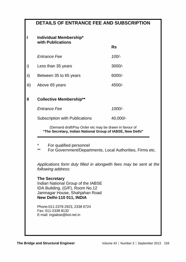
The Bridge and Structural Engineer Volume 43 Number 3 September 2013 159
C:\Documents and Settings\a\Desktop\MembershipForm.doc
DETAILS OF ENTRANCE FEE AND SUBSCRIPTION I Individual Membership* with Publications Rs Entrance Fee 100/- i) Less than 35 years 3000/- ii) Between 35 to 65 years 6000/- iii) Above 65 years 4500/- II Collective Membership** Entrance Fee 1000/- Subscription with Publications 40,000/-
(Demand draft/Pay Order etc may be drawn in favour of “The Secretary, Indian National Group of IABSE, New Delhi”
* For qualified personnel ** For Government/Departments, Local Authorities, Firms etc.
Applications form duly filled in alongwith fees may be sent at the following address:
The Secretary Indian National Group of the IABSE IDA Building, (G/F), Room No.12 Jamnagar House, Shahjahan Road New Delhi-110 011, INDIA Phone:011-2378 2923, 2338 6724 Fax: 011-2338 8132 E-mail: [email protected]
160 Volume 43 Number 3 September 2013 The Bridge and Structural Engineer
Urban Flyovers Structure, Architecture, Sustainability
B&SE_Volume 3_September 2013
The Bridge & Structural Engineer
JOURNAL OF THE INDIAN NATIONAL GROUP OF THE INTERNATIONAL
ASSOCIATION FOR BRIDGE & STRUCTURAL ENGINEERING