The BRASS Project - spacegrant.colorado.edu 2011... · Critical Design Review. ... Mechanical...
22
The BRASS Project The BRASS Project University of North Dakota University of North Dakota Matthew Voigt Nathan Ambler Ron Fevig John Nordlie Tim Young Nirmal Patel (University of North Florida) Baike Xi Joshua Peterson David Delene Len Hillhouse Telang Kaiwalya Gökhan Sever December 16 th , 2008 Balloon and Rocket Atmospheric Sampling and Sensing Critical Design Review Critical Design Review
Transcript of The BRASS Project - spacegrant.colorado.edu 2011... · Critical Design Review. ... Mechanical...
The BRASS ProjectThe BRASS Project
University of North DakotaUniversity of North DakotaMatthew VoigtNathan Ambler
Ron FevigJohn NordlieTim Young
Nirmal Patel (University of North Florida)Baike Xi
Joshua PetersonDavid DeleneLen Hillhouse
Telang KaiwalyaGökhan Sever
December 16th, 2008
Balloon and Rocket Atmospheric Sampling and Sensing
Critical Design ReviewCritical Design Review
The Objective• The altitude of the mesosphere is from 50 km to approximately 90 km.
The mesosphere is a poorly studied layer of the atmosphere since it is too high for an aircraft or balloon and too low for an orbiting spacecraft.
– To measure concentrations of H2, Ch4, CO (reducing)*, O3, O2, N2O (oxidizing)*, in the mesosphere in nearly real-time using nanocrystalline oxide semiconductor sensors arrays and also simultaneously obtain information on the magnetic field strength.
• Furthermore two additional payloads are being integrated• To measure the number of particulates in the air, using a particle counter• To inspect the ‘hardiness’ of cellular material by using lettuce sprouts
* Currently we are addressing which of these six will be measured.
Mission OverviewMission Overview
To Prove– Capability of in-situ atmospheric measurements on sounding rockets
which has already been proven successful on high altitude balloons.
To Discover– The relative amounts of H2, Ch4, CO (reducing)*, O3, O2, N2O
(oxidizing)*, gasses in the mesosphere.
Related Research– Nanocrystalline solid state gas sensor arrays developed and
fabricated by Dr. Nirmal Patel at University of North Florida (U.S. patent pending) had three balloon flights so far:
• 2007 in Florida (telemetry issues)• 2008 in North Dakota (telemetry issues)• 2008 HASP – successful flight and data obtained
Mission OverviewMission Overview
•The theory of the payloadNanocrystalline Oxide semiconductors such as Indium-tin oxide solid state sensor arrays with different types of catalytic layers and stimulators for the detection of specific gases. Sensors will be calibrated in the lab. Also, a selectivity algorithm will be determined.
Change in the electrical resistance with respect to change in the concentration of gas gives the electrical signal for the sensors.
Resistance values will be recorded using a flash memory. After data recovery and analysis, the concentration of different gases will be determined using the calibrated plots and selectivity algorithm.
Some of the particulate will be collected on the adhesive surface of tape. The morphology of particulate will be examined using scanning electron microscope (SEM), while chemical composition will be determined using energy dispersive analysis of x-rays (EDAX).
The bio payload will undergo decompression, exposing the payload to vacuum.
Mission OverviewMission Overview
The theory of the dataThe data can assist to the models of our current atmosphere.
The surface morphology of sensors before launch and after recovery will be examined using SEM, while EDAX will be used to check the chemical composition of the surface of sensors.
The particle counter uses a laser which interacts with the particulates that pass by, scattering the light downward onto the optical sensor, measuring the particulate.
Mission OverviewMission Overview
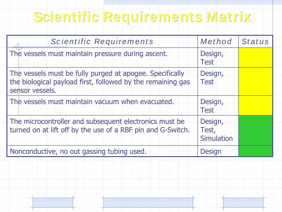
Scientific Requirements MatrixScientific Requirements Matrix
Scientific Requirements Method Status
The vessels must maintain pressure during ascent. Design, Test
The vessels must be fully purged at apogee. Specifically the biological payload first, followed by the remaining gas sensor vessels.
Design, Test
The vessels must maintain vacuum when evacuated. Design, Test
The microcontroller and subsequent electronics must be turned on at lift off by the use of a RBF pin and G-Switch.
Design, Test, Simulation
Nonconductive, no out gassing tubing used. Design
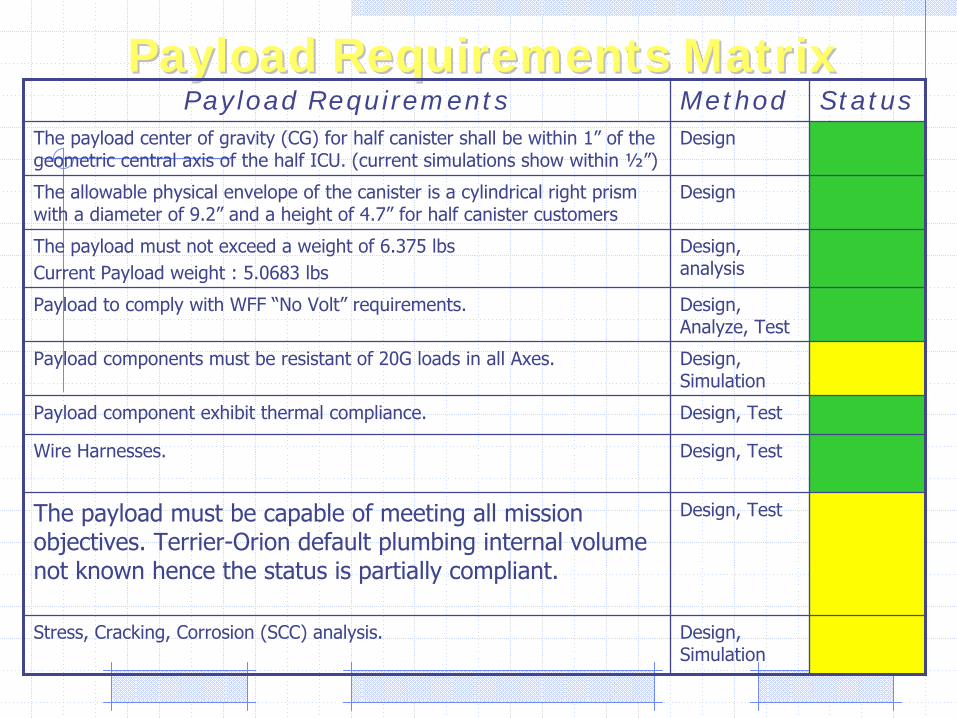
Payload Requirements MatrixPayload Requirements MatrixPayload Requirements Method Status
The payload center of gravity (CG) for half canister shall be within 1”
of the geometric central axis of the half ICU. (current simulations show within ½”)
Design
The allowable physical envelope of the canister is a cylindrical
right prism with a diameter of 9.2”
and a height of 4.7”
for half canister customersDesign
The payload must not exceed a weight of 6.375 lbsCurrent Payload weight : 5.0683 lbs
Design, analysis
Payload to comply with WFF “No Volt”
requirements. Design, Analyze, Test
Payload components must be resistant of 20G loads in all Axes. Design, Simulation
Payload component exhibit thermal compliance. Design, Test
Wire Harnesses. Design, Test
The payload must be capable of meeting all mission objectives. Terrier-Orion default plumbing internal volume not known hence the status is partially compliant.
Design, Test
Stress, Cracking, Corrosion (SCC) analysis. Design, Simulation
2
1
3
4
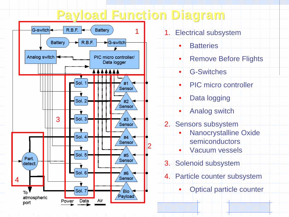
1. Electrical subsystem
• Batteries
• Remove Before Flights
• G-Switches
• PIC micro controller
• Data logging
• Analog switch
2. Sensors subsystem• Nanocrystalline Oxide
semiconductors • Vacuum vessels
3. Solenoid subsystem
4. Particle counter subsystem
• Optical particle counter
Payload Function DiagramPayload Function Diagram
Payload Mechanical DesignPayload Mechanical Design
The assembly was created using ProE Wildfire 4.0. Payload assembly shown in the next couple of slides comprises of different materials.
Green: PCB, Sky Blue (dull): Subassembly of different materials,
Navy blue (dark): Steel components, Metallic gray: Al 6061, Transparent gray: Polycarbonate plates.
Payload height and interfacing are illustrated and explained on the following figures.
All the structural components will be manufactured in-house.
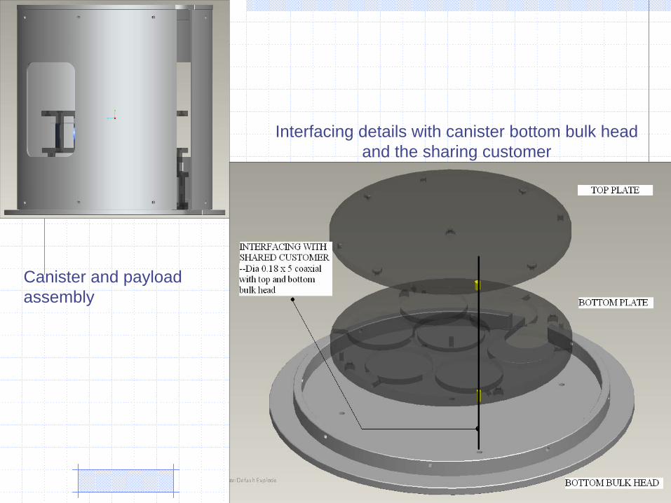
Canister and payload assembly
Interfacing details with canister bottom bulk headand the sharing customer
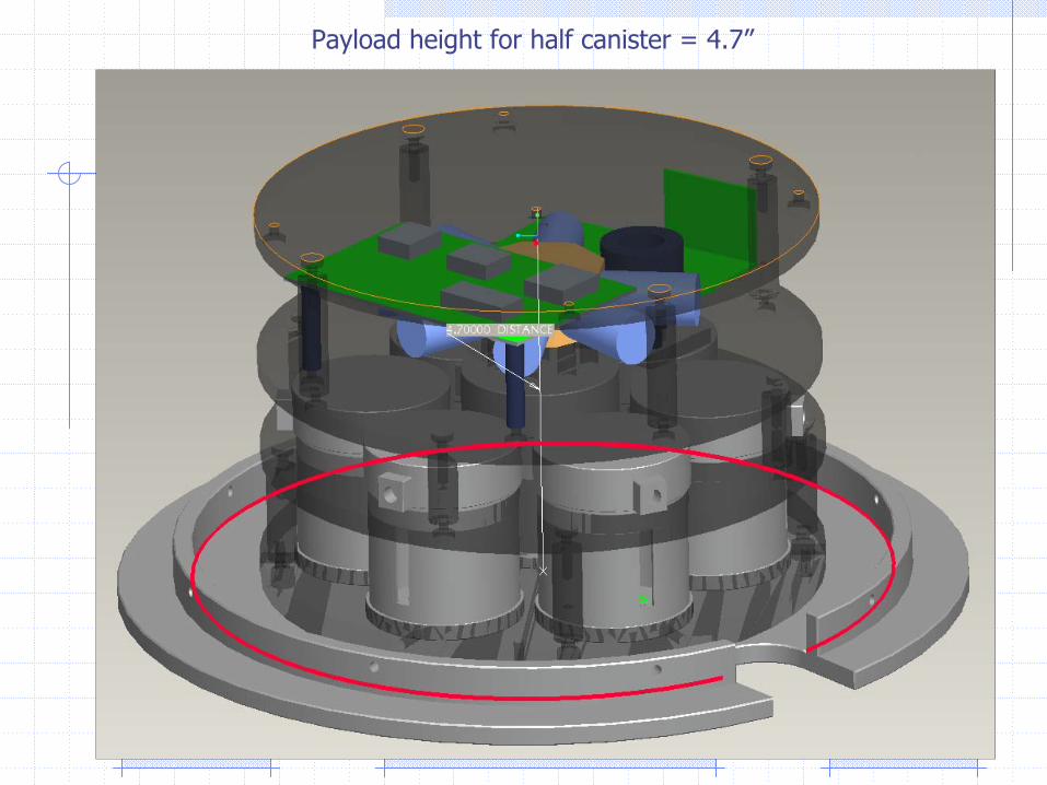
Payload height for half canister = 4.7”
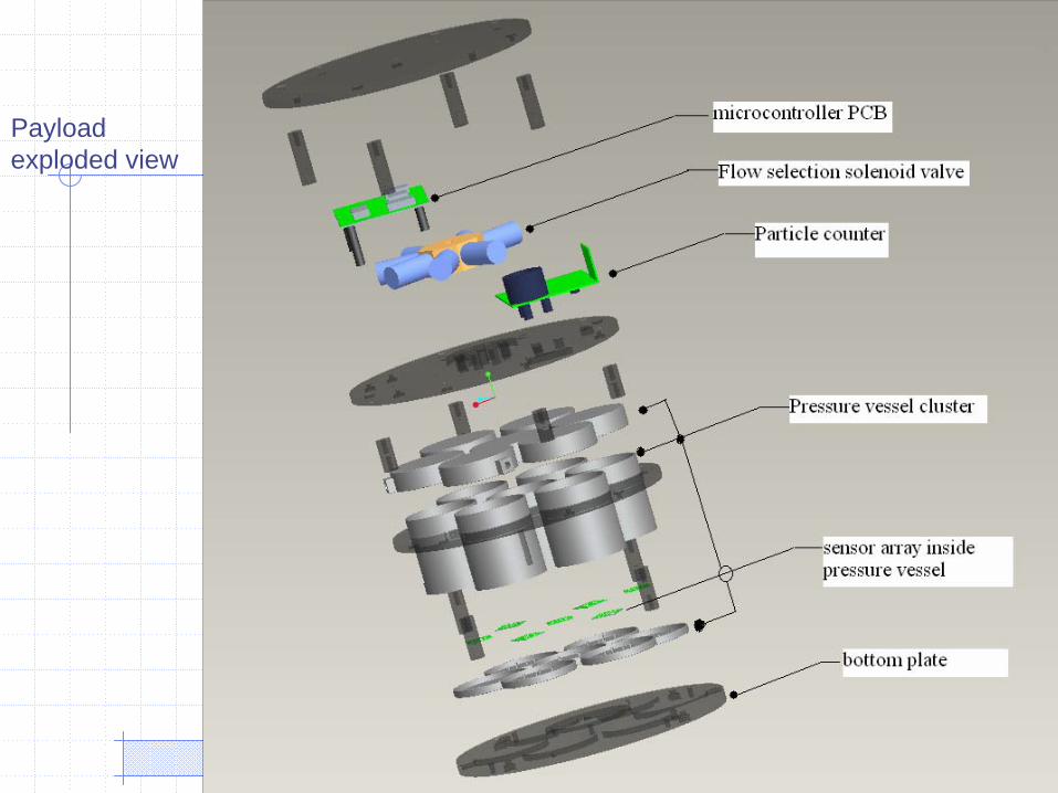
Payloadexploded view
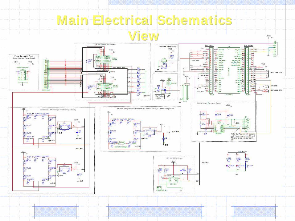
Main Electrical Schematics Main Electrical Schematics View View
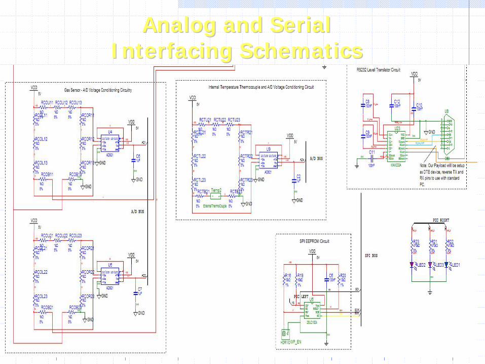
Analog and Serial Analog and Serial Interfacing SchematicsInterfacing Schematics
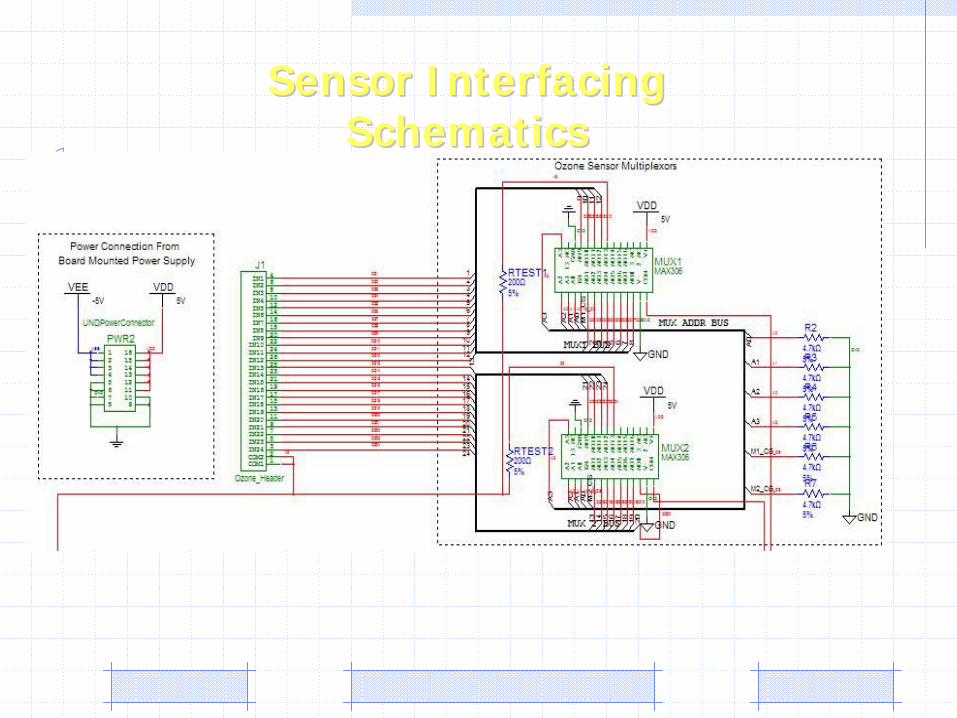
Sensor Interfacing Sensor Interfacing SchematicsSchematics
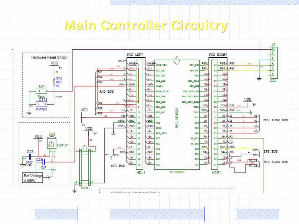
Main Controller CircuitryMain Controller Circuitry
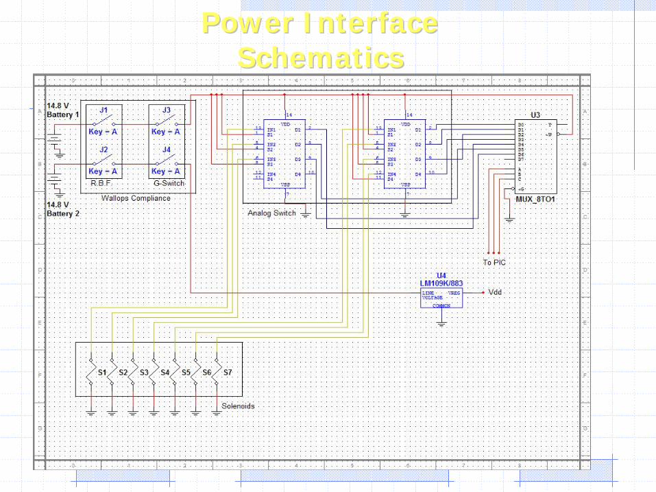
Power Interface Power Interface SchematicsSchematics
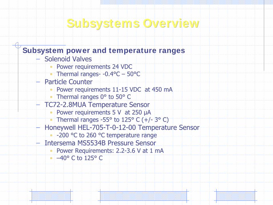
Subsystem power and temperature ranges–
Solenoid Valves•
Power requirements 24 VDC•
Thermal ranges-
-0.4°C –
50°C–
Particle Counter•
Power requirements 11-15 VDC at 450 mA•
Thermal ranges 0°
to 50°
C–
TC72-2.8MUA Temperature Sensor•
Power requirements 5 V at 250 μA•
Thermal ranges -55°
to 125°
C (+/-
3°
C)–
Honeywell HEL-705-T-0-12-00 Temperature Sensor•
-200 °C to 260 °C temperature range–
Intersema
MS5534B Pressure Sensor•
Power Requirements: 2.2-3.6 V at 1 mA•
–40°
C to 125°
C
Subsystems OverviewSubsystems Overview
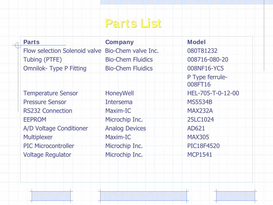
Parts Company ModelFlow selection Solenoid valve Bio-Chem
valve Inc.
080T81232Tubing (PTFE)
Bio-Chem
Fluidics
008716-080-20Omnilok-
Type P Fitting
Bio-Chem
Fluidics
008NF16-YC5P Type ferrule-
008FT16
Temperature Sensor
HoneyWell
HEL-705-T-0-12-00Pressure Sensor
Intersema
MS5534B RS232 Connection Maxim-IC
MAX232AEEPROM Microchip Inc.
25LC1024A/D Voltage Conditioner Analog Devices
AD621Multiplexer Maxim-IC MAX305 PIC Microcontroller
Microchip Inc. PIC18F4520Voltage Regulator Microchip Inc.
MCP1541
Parts ListParts List
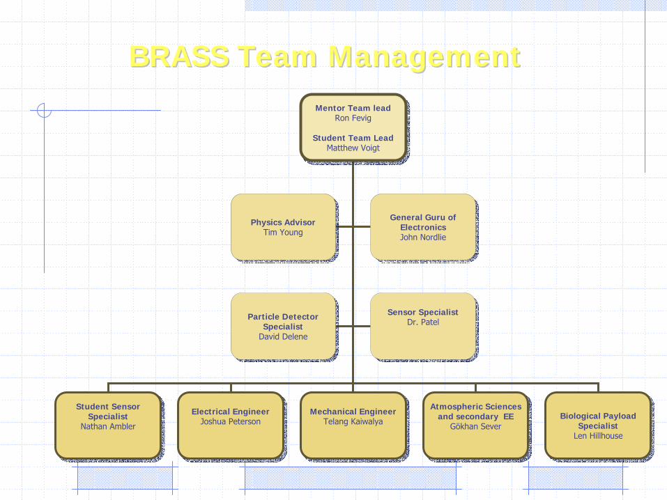
Mentor Team leadRon Fevig
Student Team LeadMatthew Voigt
Mentor Team leadRon Fevig
Student Team LeadMatthew Voigt
Student Sensor Specialist
Nathan Ambler
Student Sensor Specialist
Nathan AmblerElectrical Engineer
Joshua PetersonElectrical Engineer
Joshua PetersonMechanical Engineer
Telang KaiwalyaMechanical Engineer
Telang KaiwalyaAtmospheric Sciences
and secondary EEGökhan Sever
Atmospheric Sciences and secondary EE
Gökhan Sever Biological Payload
SpecialistLen Hillhouse
Biological Payload Specialist
Len Hillhouse
Physics AdvisorTim Young
Physics AdvisorTim Young
General Guru of ElectronicsJohn Nordlie
General Guru of ElectronicsJohn Nordlie
Particle Detector Specialist
David Delene
Particle Detector Specialist
David Delene
Sensor SpecialistDr. Patel
Sensor SpecialistDr. Patel
BRASS Team ManagementBRASS Team Management
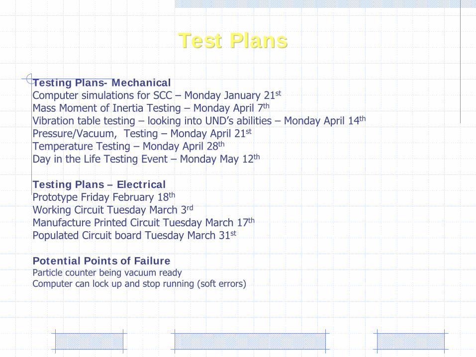
Testing Plans- MechanicalComputer simulations for SCC –
Monday January 21st
Mass Moment of Inertia Testing –
Monday April 7th
Vibration table testing –
looking into UND’s
abilities –
Monday April 14th
Pressure/Vacuum, Testing –
Monday April 21st
Temperature Testing –
Monday April 28th
Day in the Life Testing Event –
Monday May 12th
Testing Plans – Electrical Prototype Friday February 18th
Working Circuit Tuesday March 3rd
Manufacture Printed Circuit Tuesday March 17th
Populated Circuit board Tuesday March 31st
Potential Points of FailureParticle counter being vacuum readyComputer can lock up and stop running (soft errors)
Test PlansTest Plans
–
Issues and concernsPossibility of flightPlumbing volume in rocketArgon gas ventingBattery chemistryCoordination with canister partner Apogee detection
Issues and ConcernsIssues and Concerns