The BlackWidow High-Radix Clos Network - Stanford...
12
The BlackWidow High-Radix Clos Network Steve Scott ∗ Dennis Abts ∗ John Kim † William J. Dally † [email protected] [email protected] [email protected] [email protected] ∗ Cray Inc. † Stanford University Chippewa Falls, Wisconsin 54729 Computer Systems Laboratory Stanford, California 94305 Abstract This paper describes the radix-64 folded-Clos network of the Cray BlackWidow scalable vector multiprocessor. We describe the BlackWidow network which scales to 32K processors with a worst- case diameter of seven hops, and the underlying high-radix router microarchitecture and its implementation. By using a high-radix router with many narrow channels we are able to take advantage of the higher pin density and faster signaling rates available in modern ASIC technology. The BlackWidow router is an 800 MHz ASIC with 64 18.75Gb/s bidirectional ports for an aggregate off- chip bandwidth of 2.4Tb/s. Each port consists of three 6.25Gb/s differential signals in each direction. The router supports deter- ministic and adaptive packet routing with separate buffering for request and reply virtual channels. The router is organized hier- archically [13] as an 8×8 array of tiles which simplifies arbitra- tion by avoiding long wires in the arbiters. Each tile of the array contains a router port, its associated buffering, and an 8×8 router subswitch. The router ASIC is implemented in a 90nm CMOS stan- dard cell ASIC technology and went from concept to tapeout in 17 months. 1 Introduction The interconnection network plays a critical role in the cost and performance of a scalable multiprocessor. It determines the point-to-point and global bandwidth of the system, as well as the latency for remote communication. Latency is particularly impor- tant for shared-memory multiprocessors, in which memory access and synchronization latencies can significantly impact application scalability, and is becoming a greater concern as system sizes grow and clock cycles shrink. The Cray BlackWidow system is designed to run demanding applications with high communication requirements. It provides a globally shared memory with direct load/store access, and, unlike conventional microprocessors, each processor in the BlackWidow system can support thousands of outstanding global memory refer- ences. The network must therefore provide very high global band- width, while also providing low latency for efficient synchroniza- tion and scalability. Over the past 15 years the vast majority of interconnection net- works have used low-radix topologies. Many mutiprocessors have used a low-radix k-ary n-cube or torus topology [6] including the SGI Origin2000 hypercube [14], the dual-bristled, sliced 2-D torus of the Cray X1 [3], the 3-D torus of the Cray T3E [20] and Cray XT3 [5], and the torus of the Alpha 21364 [18]. The Quadrics switch [1] uses a radix-8 router, the Mellanox router [17] is radix- 24, and the highest radix available from Myrinet is radix-32 [19]. The IBM SP2 switch [22] is radix-8. The BlackWidow network uses a high-radix folded Clos [2] or fat-tree [15] topology with sidelinks. A low-radix fat-tree topol- ogy was used in the the CM-5 [16], and this topology is also used in many clusters, including the Cray XD1 [4]. The BlackWidow topology extends this previous work by using a high-radix and adding sidelinks to the topology. During the past 15 years, the total bandwidth per router has increased by nearly three orders of magnitude, due to a combina- tion of higher pin density and faster signaling rates, while typi- cal packet sizes have remained roughly constant. This increase in router bandwidth relative to packet size motivates networks built from many thin links rather than fewer fat links as in the recent past[13]. Building a network using high-radix routers with many narrow ports reduces the latency and cost of the resulting network. The design of the YARC 1 router and BlackWidow network make several contributions to the field of interconnection network design: • The BlackWidow topology extends the folded-Clos topology to include sidelinks, which allow the global network band- width to be statically partitioned among the peer subtrees, reducing the cost and the latency of the network. • The YARC microarchitecture is adapted to the constraints imposed by modern ASIC technology — abundant wiring but limited buffers. The abundant wiring available in the ASIC process enabled an 8× speedup in the column orga- nization of the YARC switch, greatly simplifying global ar- bitration. At the same time, wormhole flow control was used internal to YARC because insufficient buffers were available to support virtual cut-through flow control. • YARC provides fault tolerance by using a unique routing ta- ble structure to configure the network to avoid bad links and nodes. YARC also provides link-level retry and automati- 1 YARC stands for ’Yet Another Router Chip’, and is also Cray spelled backwards.
Transcript of The BlackWidow High-Radix Clos Network - Stanford...

The BlackWidow High-Radix Clos Network
Steve Scott∗ Dennis Abts∗ John Kim† William J. Dally†
[email protected] [email protected] [email protected] [email protected]
∗Cray Inc. † Stanford UniversityChippewa Falls, Wisconsin 54729 Computer Systems Laboratory
Stanford, California 94305
Abstract
This paper describes the radix-64 folded-Clos network of theCray BlackWidow scalable vector multiprocessor. We describe theBlackWidow network which scales to 32K processors with a worst-case diameter of seven hops, and the underlying high-radix routermicroarchitecture and its implementation. By using a high-radixrouter with many narrow channels we are able to take advantageof the higher pin density and faster signaling rates available inmodern ASIC technology. The BlackWidow router is an 800 MHzASIC with 64 18.75Gb/s bidirectional ports for an aggregate off-chip bandwidth of 2.4Tb/s. Each port consists of three 6.25Gb/sdifferential signals in each direction. The router supports deter-ministic and adaptive packet routing with separate buffering forrequest and reply virtual channels. The router is organized hier-archically [13] as an 8×8 array of tiles which simplifies arbitra-tion by avoiding long wires in the arbiters. Each tile of the arraycontains a router port, its associated buffering, and an 8×8 routersubswitch. The router ASIC is implemented in a 90nm CMOS stan-dard cell ASIC technology and went from concept to tapeout in 17months.
1 Introduction
The interconnection network plays a critical role in the costand performance of a scalable multiprocessor. It determines thepoint-to-point and global bandwidth of the system, as well as thelatency for remote communication. Latency is particularly impor-tant for shared-memory multiprocessors, in which memory accessand synchronization latencies can significantly impact applicationscalability, and is becoming a greater concern as system sizes growand clock cycles shrink.
The Cray BlackWidow system is designed to run demandingapplications with high communication requirements. It provides aglobally shared memory with direct load/store access, and, unlikeconventional microprocessors, each processor in the BlackWidowsystem can support thousands of outstanding global memory refer-ences. The network must therefore provide very high global band-width, while also providing low latency for efficient synchroniza-tion and scalability.
Over the past 15 years the vast majority of interconnection net-works have used low-radix topologies. Many mutiprocessors have
used a low-radix k-ary n-cube or torus topology [6] including theSGI Origin2000 hypercube [14], the dual-bristled, sliced 2-D torusof the Cray X1 [3], the 3-D torus of the Cray T3E [20] and CrayXT3 [5], and the torus of the Alpha 21364 [18]. The Quadricsswitch [1] uses a radix-8 router, the Mellanox router [17] is radix-24, and the highest radix available from Myrinet is radix-32 [19].The IBM SP2 switch [22] is radix-8.
The BlackWidow network uses a high-radix folded Clos [2] orfat-tree [15] topology with sidelinks. A low-radix fat-tree topol-ogy was used in the the CM-5 [16], and this topology is also usedin many clusters, including the Cray XD1 [4]. The BlackWidowtopology extends this previous work by using a high-radix andadding sidelinks to the topology.
During the past 15 years, the total bandwidth per router hasincreased by nearly three orders of magnitude, due to a combina-tion of higher pin density and faster signaling rates, while typi-cal packet sizes have remained roughly constant. This increase inrouter bandwidth relative to packet size motivates networks builtfrom many thin links rather than fewer fat links as in the recentpast[13]. Building a network using high-radix routers with manynarrow ports reduces the latency and cost of the resulting network.
The design of the YARC1 router and BlackWidow networkmake several contributions to the field of interconnection networkdesign:
• The BlackWidow topology extends the folded-Clos topologyto include sidelinks, which allow the global network band-width to be statically partitioned among the peer subtrees,reducing the cost and the latency of the network.
• The YARC microarchitecture is adapted to the constraintsimposed by modern ASIC technology — abundant wiringbut limited buffers. The abundant wiring available in theASIC process enabled an 8× speedup in the column orga-nization of the YARC switch, greatly simplifying global ar-bitration. At the same time, wormhole flow control was usedinternal to YARC because insufficient buffers were availableto support virtual cut-through flow control.
• YARC provides fault tolerance by using a unique routing ta-ble structure to configure the network to avoid bad links andnodes. YARC also provides link-level retry and automati-
1YARC stands for ’Yet Another Router Chip’, and is also Cray spelledbackwards.

cally reconfigures to reduce channel width to avoid a faultybit or bits.
• YARC employs both an adaptive routing method and a deter-ministic routing method based on address hashing to balanceload across network channels and routers.
This paper describes the BlackWidow (BW) multiprocessornetwork and the microarchitecture of YARC, the high-radix routerchip used in the BW network. The rest of the paper is organizedas follows. An overview of the BlackWidow network and thehigh-radix Clos topology is described in Section 2. We providean overview of the microarchitecture of the YARC router used inthe BlackWidow network in Section 3. In Section 4, the commu-nication stack of the router is discussed and the routing within theBlackWidow network is described in Section 5. The implemen-tation of the YARC router is described in Section 6. We providesome discussions in Section 7 on key design points of the Black-Widow network and the YARC router, and present conclusion inSection 8.
2 The BlackWidow Network
2.1 System Overview
The Cray BlackWidow multiprocessor is the follow-on to theCray X1. It is a distributed shared memory multiprocessor builtwith high performance, high bandwidth custom processors. Theprocessors support latency hiding, addressing and synchronizationfeatures that facilitate scaling to large system sizes. Each Black-Widow processor is implemented on a single chip and includes a4-way-dispatch scalar core, 8 vector pipes, two levels of cache anda set of ports to the local memory system.
The system provides a shared memory with global load/storeaccess. It is globally cache coherent, but each processor onlycaches data from memory within its four-processor node. Thisprovides natural support for SMP applications on a single node,and hierarchical (e.g.: shmem or MPI on top of OpenMP) applica-tions across the entire machine. Pure distributed memory applica-tions (MPI, shmem, CAF, UPC) are of course also supported, andexpected to represent the bulk of the workload.
2.2 Topology and Packaging
The BlackWidow network uses YARC high-radix routers, eachof which has 64 ports that are three bits wide in each direction.Each BW processor has four injection ports into the network (Fig-ure 1), with each port connecting to a different network slice. Eachslice is a completely separate network with its own set of YARCrouter chips. The discussion of the topology in this section focuseson a single slice of the network.
The BlackWidow network scales up to 32K processors usinga variation on a folded-Clos or fat-tree network topology that canbe incrementally scaled. The BW system is packaged in mod-ules, chassis, and cabinets. Each compute module contains eightprocessors with four network ports each. A chassis holds eightcompute modules organized as two 32-processor rank 1 (R1) sub-trees, and up to four R1 router modules (each of which providestwo network slices for one of the subtrees). Each R1 router module
Figure 1. The BlackWidow network building blocks are32-processor local groups connected via two rank 1router modules each with two YARC (Y) router chips.
contains two 64-port YARC router chips (Figure 1) providing 64downlinks that are routed to the processor ports via a mid-plane,and 64 uplinks (or sidelinks) that are routed to eight 96-pin cableconnectors that carry eight links each.2 Each cabinet holds twochassis (128 processors) organized as four 32-processors R1 sub-trees. Machines with up to 288 processors, nine R1 subtrees, canbe connected by directly cabling the R1 subtrees to one another us-ing sidelinks as shown in 2(a) and 2(b) to create a rank 1.5 (R1.5)network.
To scale beyond 288 processors, the uplink cables from eachR1 subtree are connected to rank 2 (R2) routers. A rank 2/3 routermodule (Figure 2c) packages four YARC router chips on an R2/R3module. The four radix-64 YARC chips on the R2/R3 module areeach split into two radix-32 virtual routers (see Section 7.4). Log-ically, each R2/R3 module has eight radix-32 routers providing256 network links on 32 cable connectors. Up to 16 R2/R3 routermodules are packaged into a stand-alone router cabinet.
Machines of up to 1024 processors can be constructed by con-necting up to 32 32-processor R1 subtrees to R2 routers. Machinesof up to 4.5K processors can be constructed by connecting up to9 512-processor R2 subtrees via side links. Up to 16K proces-sors may be connected by a rank 3 (R3) network where up to 32512-processor R2 subtrees are connected by R3 routers. In theorynetworks up to 72K processors could be constructed by connect-ing nine R3 subtrees via side links; however, the maximum-sizeBW system is 32K processors.
The BW topology and packaging scheme enables very flexibleprovisioning of network bandwidth. For instance, by only using
2Each network cable carries eight links to save cost and mitigate cablebulk.
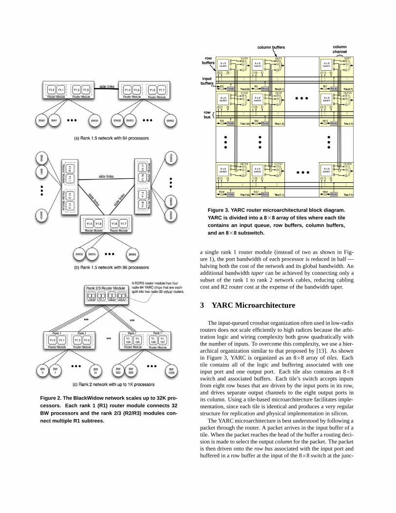
Figure 2. The BlackWidow network scales up to 32K pro-cessors. Each rank 1 (R1) router module connects 32BW processors and the rank 2/3 (R2/R3) modules con-nect multiple R1 subtrees.
Figure 3. YARC router microarchitectural block diagram.YARC is divided into a 8×8 array of tiles where each tilecontains an input queue, row buffers, column buffers,and an 8×8 subswitch.
a single rank 1 router module (instead of two as shown in Fig-ure 1), the port bandwidth of each processor is reduced in half —halving both the cost of the network and its global bandwidth. Anadditional bandwidth taper can be achieved by connecting only asubset of the rank 1 to rank 2 network cables, reducing cablingcost and R2 router cost at the expense of the bandwidth taper.
3 YARC Microarchitecture
The input-queued crossbar organization often used in low-radixrouters does not scale efficiently to high radices because the arbi-tration logic and wiring complexity both grow quadratically withthe number of inputs. To overcome this complexity, we use a hier-archical organization similar to that proposed by [13]. As shownin Figure 3, YARC is organized as an 8×8 array of tiles. Eachtile contains all of the logic and buffering associated with oneinput port and one output port. Each tile also contains an 8×8switch and associated buffers. Each tile’s switch accepts inputsfrom eight row buses that are driven by the input ports in its row,and drives separate output channels to the eight output ports inits column. Using a tile-based microarchitecture facilitates imple-mentation, since each tile is identical and produces a very regularstructure for replication and physical implementation in silicon.
The YARC microarchitecture is best understood by following apacket through the router. A packet arrives in the input buffer of atile. When the packet reaches the head of the buffer a routing deci-sion is made to select the output column for the packet. The packetis then driven onto the row bus associated with the input port andbuffered in a row buffer at the input of the 8×8 switch at the junc-

Figure 4. YARC pipeline diagram shows the tile divided into three blocks: input queue, subswitch, and column buffers.
tion of the packet’s input row and output column. At this point therouting decision must be refined to select a particular output portwithin the output column. The switch then routes the packet tothe column channel associated with the selected output port. Thecolumn channel delivers the packet to an output buffer (associatedwith the input row) at the output port multiplexer. Packets in theper-input-row output buffers arbitrate for access to the output portand, when granted access, are switched onto the output port viathe multiplexer.
There are three sets of buffers in YARC: input buffers, rowbuffers, and column buffers. Each buffer is partitioned into twovirtual channels. One input buffer and 8 row buffers are associ-ated with each input port. Thus, no arbitration is needed to allocatethese buffers — only flow control. Eight column buffers are asso-ciated with each subswitch. Allocation of these column bufferstakes place at the same time the packet is switched.
Like the design of [13], output arbitration is performed in twostages. The first stage of arbitration is done to gain access to theoutput of the subswitch. A packet then competes with packetsfrom other tiles in the same column in the second stage of arbitra-tion for access to the output port. Unlike the hierarchical cross-bar in [13], the YARC router takes advantage of the abundant on-chip wiring resources to run separate channels from each output ofeach subswitch to the corresponding output port. This organiza-tion places the column buffers in the output tiles rather than at theoutput of the subswitches. Co-locating the eight column buffersassociated with a given output in a single tile simplifies globaloutput arbitration. With column buffers at the outputs of the sub-switch, the requests/grants to/from the global arbiters would needto be pipelined to account for wire delay which would complicatethe arbitration logic.
As shown in Figure 4, a packet traversing the YARC routerpasses through 25 pipeline stages which results in a zero-load la-tency of 31.25ns. To simplify implementation of YARC, each ma-jor block: input queue, subswitch, and column buffers, was de-signed with both input and output registers. This approach simpli-fied system timing at the expense of latency. During the design,additional pipeline stages were inserted to pipeline the wire delayassociated with the row busses and the column channels.
4 Communication Stack
This section describes the three layers of the communicationstack: network layer, data-link layer, and physical layer. We dis-cuss the packet format, flow control across the network links, thelink control block (LCB) which implements the data-link layer,and the serializer/deserializer (SerDes) at the physical layer.
4.1 Packet Format
The format of a packet within the BlackWidow network isshown in Figure 5. Packets are divided into 24-bit phits for trans-mission over internal YARC datapaths. These phits are furtherserialized for transmission over 3-bit wide network channels. Aminimum packet contains 4 phits carrying 32 payload bits. Longerpackets are constructed by inserting additional payload phits (likethe third phit in the figure) before the tail phit. Two-bits of eachphit, as well as all of the tail phit are used by the data-link layer.
The head phit of the packet controls routing which will be de-scribed in detail in Section 5. In addition to specifying the destina-tion, this phit contains a v bit that specifies which virtual channelto use, and three bits, h, a, and r, that control routing. If the rbit is set, the packet will employ source routing. In this case, thepacket header will be accompanied by a routing vector that indi-cates the path through the network as a list of ports to select theoutput port at each hop. Source routed packets are used only formaintenance operations such as reading and writing configurationregisters on the YARC. If the a bit is set, the packet will routeadaptively, otherwise it will route deterministically. If the h bit isset, the deterministic routing algorithm employs the hash bits inthe second phit to select the output port.
4.2 Network Layer Flow Control
The allocation unit for flow control is a 24-bit phit — thus,the phit is really the flit (flow control unit). The BlackWidow net-work uses two virtual channels (VCs) [7], designated request (v=0)and response (v=1) to avoid request-response deadlocks in the net-work. Therefore, all buffer resources are allocated according tothe virtual channel bit in the head phit. Each input buffer is 256phits and is sized to cover the round-trip latency across the net-work channel. Virtual cut-through flow control [12] is used acrossthe network links.
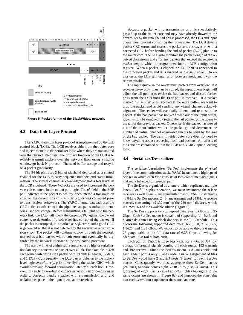
Figure 5. Packet format of the BlackWidow network.
4.3 Data-link Layer Protocol
The YARC data-link layer protocol is implemented by the linkcontrol block (LCB). The LCB receives phits from the router coreand injects them into the serializer logic where they are transmittedover the physical medium. The primary function of the LCB is toreliably transmit packets over the network links using a slidingwindow go-back-N protocol. The send buffer storage and retry ison a packet granularity.
The 24-bit phit uses 2-bits of sideband dedicated as a controlchannel for the LCB to carry sequence numbers and status infor-mation. The virtual channel acknowledgment status bits travel inthe LCB sideband. These VC acks are used to increment the per-vc credit counters in the output port logic. The ok field in the EOPphit indicates if the packet is healthy, encountered a transmissionerror on the current link (transmit error), or was corrupted priorto transmission (soft error). The YARC internal datapath uses theCRC to detect soft errors in the pipeline data paths and static mem-ories used for storage. Before transmitting a tail phit onto the net-work link, the LCB will check the current CRC against the packetcontents to determine if a soft error has corrupted the packet. Ifthe packet is corrupted, it is marked as soft error, and a good CRCis generated so that it is not detected by the receiver as a transmis-sion error. The packet will continue to flow through the networkmarked as a bad packet with a soft error and eventually be dis-carded by the network interface at the destination processor.
The narrow links of a high-radix router cause a higher serializa-tion latency to squeeze the packet over a link. For example, a 32Bcache-line write results in a packet with 19 phits (6 header, 12 data,and 1 EOP). Consequently, the LCB passes phits up to the higher-level logic speculatively, prior to verifying the packet CRC, whichavoids store-and-forward serialization latency at each hop. How-ever, this early forwarding complicates various error conditions inorder to correctly handle a packet with a transmission error andreclaim the space in the input queue at the receiver.
Because a packet with a transmission error is speculativelypassed up to the router core and may have already flowed to thenext router by the time the tail phit is processed, the LCB and inputqueue must prevent corrupting the router state. The LCB detectspacket CRC errors and marks the packet as transmit error with acorrected CRC before handing the end-of-packet (EOP) phit up tothe router core. The LCB also monitors the packet length of the re-ceived data stream and clips any packets that exceed the maximumpacket length, which is programmed into an LCB configurationregister. When a packet is clipped, an EOP phit is appended tothe truncated packet and it is marked as transmit error. On ei-ther error, the LCB will enter error recovery mode and await theretransmission.
The input queue in the router must protect from overflow. If itreceives more phits than can be stored, the input queue logic willadjust the tail pointer to excise the bad packet and discard furtherphits from the LCB until the EOP phit is received. If a packetmarked transmit error is received at the input buffer, we want todrop the packet and avoid sending any virtual channel acknowl-edgments. The sender will eventually timeout and retransmit thepacket. If the bad packet has not yet flowed out of the input buffer,it can simply be removed by setting the tail pointer of the queue tothe tail of the previous packet. Otherwise, if the packet has flowedout of the input buffer, we let the packet go and decrement thenumber of virtual channel acknowledgments to send by the sizeof the bad packet. The transmit-side router core does not need toknow anything about recovering from bad packets. All effects ofthe error are contained within the LCB and YARC input queueinglogic.
4.4 Serializer/Deserializer
The serializer/deserializer (SerDes) implements the physicallayer of the communication stack. YARC instantiates a high-speedSerDes in which each lane consists of two complimentary signalsmaking a balanced differential pair.
The SerDes is organized as a macro which replicates multiplelanes. For full duplex operation, we must instantiate the 8-lanereceiver as well as an 8-lane transmitter macro. YARC instantiates48 8-lane SerDes macros, 24 8-lane transmit and 24 8-lane receivemacros, consuming ≈91.32 mm2 of the 289 mm2 die area, whichis almost 1/3 of the available silicon (Figure 6).
The SerDes supports two full-speed data rates: 5 Gbps or 6.25Gbps. Each SerDes macro is capable of supporting full, half, andquarter data rates using clock dividers in the PLL module. Thisallows the following supported data rates: 6.25, 5.0, 3.125, 2.5,1.5625, and 1.25 Gbps. We expect to be able to drive a 6 meter,26 gauge cable at the full data rate of 6.25 Gbps, allowing foradequate PCB foil at both ends.
Each port on YARC is three bits wide, for a total of 384 lowvoltage differential signals coming off each router, 192 transmitand 192 receive. Since the SerDes macro is 8 lanes wide andeach YARC port is only 3 lanes wide, a naive assignment of tilesto SerDes would have 2 and 2/3 ports (8 lanes) for each SerDesmacro. Consequently, we must aggregate three SerDes macros(24 lanes) to share across eight YARC tiles (also 24 lanes). Thisgrouping of eight tiles is called an octant (tiles belonging to thesame octant are shown in Figure 6a) and imposes the constraintthat each octant must operate at the same data rate.
The SerDes has a 16/20 bit parallel interface which is managedby the link control block (LCB). The positive and negative com-ponents of each differential signal pair can be arbitrarily swappedbetween the transmit/receive pair. In addition, each of the 3 laneswhich comprise the LCB port can be permuted or “swizzled.”The LCB determines which are the positive and negative differ-ential pairs during channel initialization, as well as which lanesare “swizzled”. This degree of freedom simplifies the board-levelriver routing of the channels and reduces the number of metal lay-ers on a PCB for the router module.
5 Routing
Routing in the BlackWidow network is performed on variablelength packets. The first phit of a packet is the header, whichcontains all the mandatory routing fields, and the last phit of apacket is an end of packet (EOP) phit which contains the packetchecksum.
In a folded-Clos topology, packet routing is performed in twostages: routing up to a common ancestor of the source and desti-nation processors, and then routing down to the destination pro-cessor. Up routing can use either adaptive or deterministic rout-ing. Downrouting, however, is always deterministic, as there isonly a single path down the tree from any router to a destinationprocessor. The BlackWidow memory consistency model requiresthat requests to the same address maintain ordering in the network.Therefore, request packets always use deterministic routing. Re-sponse packets do not require ordering, and so are routed adap-tively.
Packet routing is algorithmic and distributed. At each hop inthe network, routing logic at the head of the input queue calculatesthe output port for the local router. This is performed using rout-ing registers and an eight-entry routing table. The routing logic isreplicated in each tile, allowing multiple virtual routers (see Sec-tion 7.4) per physical router and providing the needed bandwidthfor parallel routing in all 64 tiles.
There are three types of links (routes):
uplinks from the injection port to a rank 1 router or a rank nrouter to a rank n + 1 router,
sidelinks from a rank n router to a peer rank n router (only forR1.5, R2.5 and R3.5 networks), and
downlinks from a rank n router to a rank n − 1 router or from arank 1 router to the destination processor.
En route from the source to the common ancestor, the packet willtake either an uplink or a sidelink depending on the class of thenetwork (e.g.: rank 2 or rank 2.5, respectively). Upon arrivalat the common ancestor, the router will begin routing the packetdown the fat tree toward its final destination using the downlinks.The down route is accomplished by extracting a logical port num-ber directly from the destination processor number. Each YARCrouter chip in the BlackWidow network has 64 ports which haveboth a physical number, and an arbitrary logical number. Sys-tem software will perform network discovery when the system isinitialized and assign a logical port number to each physical portnumber.
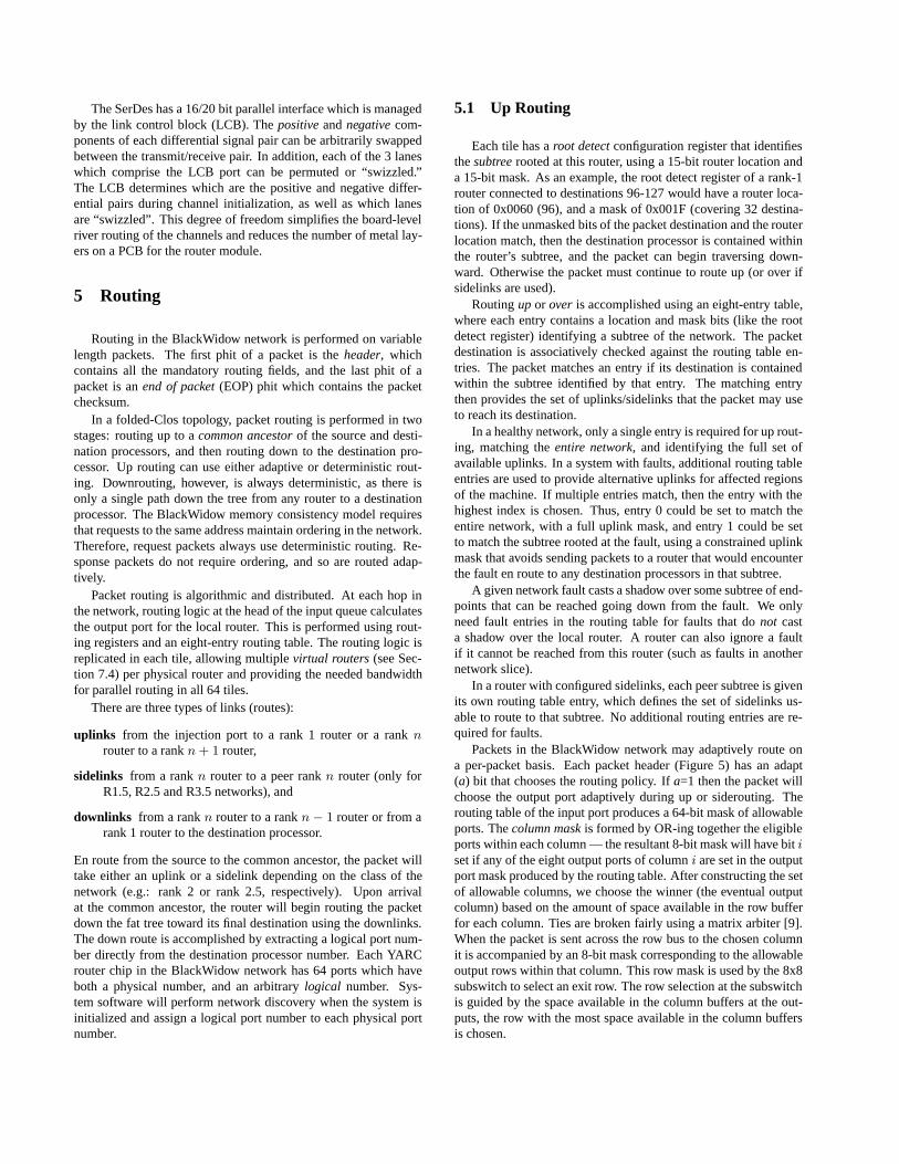
5.1 Up Routing
Each tile has a root detect configuration register that identifiesthe subtree rooted at this router, using a 15-bit router location anda 15-bit mask. As an example, the root detect register of a rank-1router connected to destinations 96-127 would have a router loca-tion of 0x0060 (96), and a mask of 0x001F (covering 32 destina-tions). If the unmasked bits of the packet destination and the routerlocation match, then the destination processor is contained withinthe router’s subtree, and the packet can begin traversing down-ward. Otherwise the packet must continue to route up (or over ifsidelinks are used).
Routing up or over is accomplished using an eight-entry table,where each entry contains a location and mask bits (like the rootdetect register) identifying a subtree of the network. The packetdestination is associatively checked against the routing table en-tries. The packet matches an entry if its destination is containedwithin the subtree identified by that entry. The matching entrythen provides the set of uplinks/sidelinks that the packet may useto reach its destination.
In a healthy network, only a single entry is required for up rout-ing, matching the entire network, and identifying the full set ofavailable uplinks. In a system with faults, additional routing tableentries are used to provide alternative uplinks for affected regionsof the machine. If multiple entries match, then the entry with thehighest index is chosen. Thus, entry 0 could be set to match theentire network, with a full uplink mask, and entry 1 could be setto match the subtree rooted at the fault, using a constrained uplinkmask that avoids sending packets to a router that would encounterthe fault en route to any destination processors in that subtree.
A given network fault casts a shadow over some subtree of end-points that can be reached going down from the fault. We onlyneed fault entries in the routing table for faults that do not casta shadow over the local router. A router can also ignore a faultif it cannot be reached from this router (such as faults in anothernetwork slice).
In a router with configured sidelinks, each peer subtree is givenits own routing table entry, which defines the set of sidelinks us-able to route to that subtree. No additional routing entries are re-quired for faults.
Packets in the BlackWidow network may adaptively route ona per-packet basis. Each packet header (Figure 5) has an adapt(a) bit that chooses the routing policy. If a=1 then the packet willchoose the output port adaptively during up or siderouting. Therouting table of the input port produces a 64-bit mask of allowableports. The column mask is formed by OR-ing together the eligibleports within each column — the resultant 8-bit mask will have bit iset if any of the eight output ports of column i are set in the outputport mask produced by the routing table. After constructing the setof allowable columns, we choose the winner (the eventual outputcolumn) based on the amount of space available in the row bufferfor each column. Ties are broken fairly using a matrix arbiter [9].When the packet is sent across the row bus to the chosen columnit is accompanied by an 8-bit mask corresponding to the allowableoutput rows within that column. This row mask is used by the 8x8subswitch to select an exit row. The row selection at the subswitchis guided by the space available in the column buffers at the out-puts, the row with the most space available in the column buffersis chosen.
Packets that are not marked as adaptive (a=0) are routed deter-ministically based on the output of a hash function. To uniformlyspread the packets across the available uplinks, the hash functiondoes an XOR of the input port, destination processor, and optionalhash bits if the hash bit (h) is set in the packet header. The hashvalue is then mapped onto the set of output links identified by therouting table. The input port and destination processor are hashedon to avoid non-uniformities in many-to-one traffic patterns. Forrequest packets, the hash bit is set, and a portion of the packet’saddress is included in the hash function to further spread the traf-fic across the uplinks. In this way, we can load balance and stillguarantee in-order delivery of packets from source to destinationtargeting a given address.
5.2 Down Routing
Once the packet reaches the common ancestor it will beginrouting down the subtree. The first step in routing down is to selecta logical downlink number. The down route configuration registercontains shift (s) and mask (m) values that are used by first right-shifting the destination processor number by s bits and then mask-ing the bottom m bits to produce the logical output port number forthe downlink. A rank 1 router, for example, would have s=0 andm=00011111. The logical port number is converted to a physicalport number by a 64-entry port mapping table. The packet pro-ceeds down the tree, shifting and masking the bits of destinationprocessor to determine the downlink at each level, until it reachesthe final egress port where it is sent to the processor’s networkinterface.
6 ASIC Implementation
This section discusses the various implementation trade-offsand challenges that were encountered during the development ofYARC. The design was implemented using standard-cell ASICtechnology from Texas Instruments. The ASIC developmentspanned 17 months and involved a team of 11 developers: ar-chitecture (2), RTL logic design (4), verification (2), RTL netlistprocessing (1), electrical and mechanical packaging (2). The 17month development pace was subdivided as:
• architecture and documentation ≈8%
• RTL logic design and verification ≈58%
• timing closure and netlist preparation ≈12%
• physical design and back-end netlist processing ≈22%
YARC is implemented in a 90nm CMOS standard-cell ASICprocess operating at 800 MHz. The silicon area is 289 mm2 (17mm on an edge) using the Texas Instruments SR50LX (low power)standard-cell ASIC library and a small number of cells from theSR50 [23] cell library for relay latches on long global wires. TheSR50 ASIC technology from Texas Instruments has a maximumgate density of 255k gates per mm2 (at 100% utilization) with a330nm minimum metal pitch and 7 layers of copper (with low-Kdielectric) interconnect.
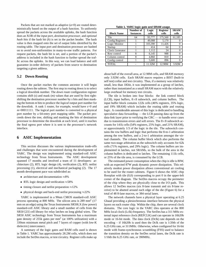
A summary of the logic gates and RAM cells used is shownin Table 1. YARC has approximately 28.2M cells, which does notinclude the SerDes macros, or test circuitry. Register cells make up
Table 1. YARC logic gate and SRAM usage.Number of Logic Register SRAM
Block Name Instances cells cells cells
Tile 64 95,777 175,560 61,185Config Registers 1 49,088 5,170 0Logic Monitor 1 103,390 11,426 0Startup 1 414 64 0Clock Generator 1 1,112 24 0Row control 8 6,145 988 0Column control 8 4,860 810 0Config control 1 5,600 896 0
TOTAL - 11.32M 12.98M 3.92M
about half of the overall area, at 12.98M cells, and SRAM memoryonly 3.92M cells. Each SRAM macro requires a BIST (built-inself test) collar and test circuitry. Thus, if a memory was relativelysmall, less than 1Kbit, it was implemented as a group of latches,rather than instantiated as a small SRAM macro with the relativelylarge overhead for memory test circuits.
The tile is broken into four blocks: the link control block(LCB), input buffers, 8×8 subswitch, and column buffers. Theinput buffer block contains 122k cells (46% registers, 35% logic,and 19% SRAM) which includes the routing table and routinglogic. A considerable amount of this logic is dedicated to handlingspeculative data forwarding — the LCB passing data up from thedata-link layer prior to verifying the CRC — to handle error casesdue to transmission errors and soft errors. The 8×8 subswitch ac-counts for 141k cells (54% registers, 25% logic, and 21% SRAM),or approximately 1/3 of the logic in the tile. The subswitch con-tains the row buffers and logic that performs the 8-to-1 arbitrationamong the row buffers, and a 2-to-1 arbitration amongst the vir-tual channels. The column buffer block which also performs thesame two-stage arbitration as the subswitch only accounts for 62kcells (71% registers, and 29% logic). The column buffers are im-plemented in latches, not SRAMs, so the bulk of the area in thecolumn buffers is dedicated to latches. The remaining 111k cells,or 25% of the tile area, is consumed by the LCB.
The estimated power consumption when the chip is idle is 80W,with an expected 87W peak dynamic power dissipation. This rel-atively modest power dissipation allows conventional air coolingto be used for the router cabinets. Figure 6 shows the ASIC chipfloorplan with tile (0,0) corresponding to port 0 in the upper-leftcorner of the diagram. The SerDes macros occupy the perimeterof the chip where they are physically close to the I/O pads. Thisallows 12 SerDes macros (six 8-lane transmit and six 8-lane re-ceive) to be abutted around each edge of the die (Figure 6) for atotal of 48 8-lane macros, or 384 serial lanes.
The network channels have a physical layer operating at 6.25Gbaud providing a plesiochronous interface between the physicallayers on each router chip. Within the chip, there are several clockdomains. The core logic in the YARC tiles operates at the 800MHz local clock (Lclk) frequency. The SerDes has a 311 MHz ex-ternal input reference clock (REFCLK) and can operate in 16b20bmode or 16-bit mode. The data clock (Dclk) rate depends on theencoding – if 16b20b is used then the Dclk rate is 1/20th of the6.25 GHz rate, or 311MHz. Otherwise, when configured for 16-bitmode with frame-synchronous scrambling (FSS) used to balancethe transition density on the SerDes serial lanes, the Dclk rate is1/16th the 6.25 GHz rate, or 390MHz.
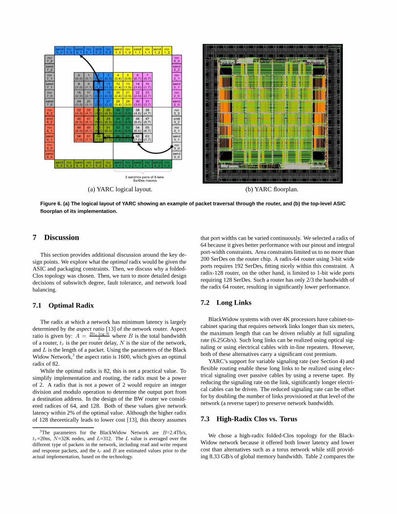
(a) YARC logical layout. (b) YARC floorplan.
Figure 6. (a) The logical layout of YARC showing an example of packet traversal through the router, and (b) the top-level ASICfloorplan of its implementation.
7 Discussion
This section provides additional discussion around the key de-sign points. We explore what the optimal radix would be given theASIC and packaging constraints. Then, we discuss why a folded-Clos topology was chosen. Then, we turn to more detailed designdecisions of subswitch degree, fault tolerance, and network loadbalancing.
7.1 Optimal Radix
The radix at which a network has minimum latency is largelydetermined by the aspect ratio [13] of the network router. Aspectratio is given by: A = Btr log N
Lwhere B is the total bandwidth
of a router, tr is the per router delay, N is the size of the network,and L is the length of a packet. Using the parameters of the BlackWidow Network,3 the aspect ratio is 1600, which gives an optimalradix of 82.
While the optimal radix is 82, this is not a practical value. Tosimplify implementation and routing, the radix must be a powerof 2. A radix that is not a power of 2 would require an integerdivision and modulo operation to determine the output port froma destination address. In the design of the BW router we consid-ered radices of 64, and 128. Both of these values give networklatency within 2% of the optimal value. Although the higher radixof 128 theoretically leads to lower cost [13], this theory assumes
3The parameters for the BlackWidow Network are B=2.4Tb/s,tr=20ns, N=32K nodes, and L=312. The L value is averaged over thedifferent type of packets in the network, including read and write requestand response packets, and the tr and B are estimated values prior to theactual implementation, based on the technology.
that port widths can be varied continuously. We selected a radix of64 because it gives better performance with our pinout and integralport-width constraints. Area constraints limited us to no more than200 SerDes on the router chip. A radix-64 router using 3-bit wideports requires 192 SerDes, fitting nicely within this constraint. Aradix-128 router, on the other hand, is limited to 1-bit wide portsrequiring 128 SerDes. Such a router has only 2/3 the bandwidth ofthe radix 64 router, resulting in significantly lower performance.
7.2 Long Links
BlackWidow systems with over 4K processors have cabinet-to-cabinet spacing that requires network links longer than six meters,the maximum length that can be driven reliably at full signalingrate (6.25Gb/s). Such long links can be realized using optical sig-naling or using electrical cables with in-line repeaters. However,both of these alternatives carry a significant cost premium.
YARC’s support for variable signaling rate (see Section 4) andflexible routing enable these long links to be realized using elec-trical signaling over passive cables by using a reverse taper. Byreducing the signaling rate on the link, significantly longer electri-cal cables can be driven. The reduced signaling rate can be offsetfor by doubling the number of links provisioned at that level of thenetwork (a reverse taper) to preserve network bandwidth.
7.3 High-Radix Clos vs. Torus
We chose a high-radix folded-Clos topology for the Black-Widow network because it offered both lower latency and lowercost than alternatives such as a torus network while still provid-ing 8.33 GB/s of global memory bandwidth. Table 2 compares the
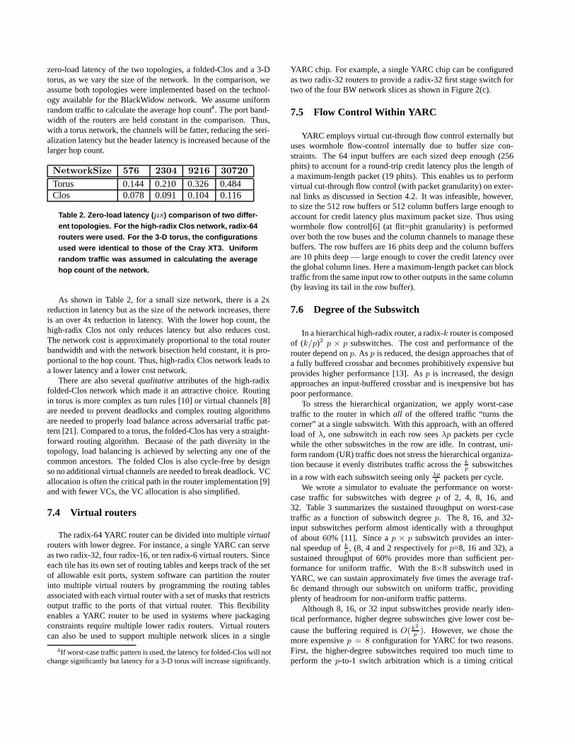
zero-load latency of the two topologies, a folded-Clos and a 3-Dtorus, as we vary the size of the network. In the comparison, weassume both topologies were implemented based on the technol-ogy available for the BlackWidow network. We assume uniformrandom traffic to calculate the average hop count4. The port band-width of the routers are held constant in the comparison. Thus,with a torus network, the channels will be fatter, reducing the seri-alization latency but the header latency is increased because of thelarger hop count.
NetworkSize 576 2304 9216 30720Torus 0.144 0.210 0.326 0.484Clos 0.078 0.091 0.104 0.116
Table 2. Zero-load latency (µs) comparison of two differ-ent topologies. For the high-radix Clos network, radix-64routers were used. For the 3-D torus, the configurationsused were identical to those of the Cray XT3. Uniformrandom traffic was assumed in calculating the averagehop count of the network.
As shown in Table 2, for a small size network, there is a 2xreduction in latency but as the size of the network increases, thereis an over 4x reduction in latency. With the lower hop count, thehigh-radix Clos not only reduces latency but also reduces cost.The network cost is approximately proportional to the total routerbandwidth and with the network bisection held constant, it is pro-portional to the hop count. Thus, high-radix Clos network leads toa lower latency and a lower cost network.
There are also several qualitative attributes of the high-radixfolded-Clos network which made it an attractive choice. Routingin torus is more complex as turn rules [10] or virtual channels [8]are needed to prevent deadlocks and complex routing algorithmsare needed to properly load balance across adversarial traffic pat-tern [21]. Compared to a torus, the folded-Clos has very a straight-forward routing algorithm. Because of the path diversity in thetopology, load balancing is achieved by selecting any one of thecommon ancestors. The folded Clos is also cycle-free by designso no additional virtual channels are needed to break deadlock. VCallocation is often the critical path in the router implementation [9]and with fewer VCs, the VC allocation is also simplified.
7.4 Virtual routers
The radix-64 YARC router can be divided into multiple virtualrouters with lower degree. For instance, a single YARC can serveas two radix-32, four radix-16, or ten radix-6 virtual routers. Sinceeach tile has its own set of routing tables and keeps track of the setof allowable exit ports, system software can partition the routerinto multiple virtual routers by programming the routing tablesassociated with each virtual router with a set of masks that restrictsoutput traffic to the ports of that virtual router. This flexibilityenables a YARC router to be used in systems where packagingconstraints require multiple lower radix routers. Virtual routerscan also be used to support multiple network slices in a single
4If worst-case traffic pattern is used, the latency for folded-Clos will notchange significantly but latency for a 3-D torus will increase significantly.
YARC chip. For example, a single YARC chip can be configuredas two radix-32 routers to provide a radix-32 first stage switch fortwo of the four BW network slices as shown in Figure 2(c).
7.5 Flow Control Within YARC
YARC employs virtual cut-through flow control externally butuses wormhole flow-control internally due to buffer size con-straints. The 64 input buffers are each sized deep enough (256phits) to account for a round-trip credit latency plus the length ofa maximum-length packet (19 phits). This enables us to performvirtual cut-through flow control (with packet granularity) on exter-nal links as discussed in Section 4.2. It was infeasible, however,to size the 512 row buffers or 512 column buffers large enough toaccount for credit latency plus maximum packet size. Thus usingwormhole flow control[6] (at flit=phit granularity) is performedover both the row buses and the column channels to manage thesebuffers. The row buffers are 16 phits deep and the column buffersare 10 phits deep — large enough to cover the credit latency overthe global column lines. Here a maximum-length packet can blocktraffic from the same input row to other outputs in the same column(by leaving its tail in the row buffer).
7.6 Degree of the Subswitch
In a hierarchical high-radix router, a radix-k router is composedof (k/p)2 p × p subswitches. The cost and performance of therouter depend on p. As p is reduced, the design approaches that ofa fully buffered crossbar and becomes prohibitively expensive butprovides higher performance [13]. As p is increased, the designapproaches an input-buffered crossbar and is inexpensive but haspoor performance.
To stress the hierarchical organization, we apply worst-casetraffic to the router in which all of the offered traffic “turns thecorner” at a single subswitch. With this approach, with an offeredload of λ, one subswitch in each row sees λp packets per cyclewhile the other subswitches in the row are idle. In contrast, uni-form random (UR) traffic does not stress the hierarchical organiza-tion because it evenly distributes traffic across the k
psubswitches
in a row with each subswitch seeing only λpk
packets per cycle.We wrote a simulator to evaluate the performance on worst-
case traffic for subswitches with degree p of 2, 4, 8, 16, and32. Table 3 summarizes the sustained throughput on worst-casetraffic as a function of subswitch degree p. The 8, 16, and 32-input subswitches perform almost identically with a throughputof about 60% [11]. Since a p × p subswitch provides an inter-nal speedup of k
p, (8, 4 and 2 respectively for p=8, 16 and 32), a
sustained throughput of 60% provides more than sufficient per-formance for uniform traffic. With the 8×8 subswitch used inYARC, we can sustain approximately five times the average traf-fic demand through our subswitch on uniform traffic, providingplenty of headroom for non-uniform traffic patterns.
Although 8, 16, or 32 input subswitches provide nearly iden-tical performance, higher degree subswitches give lower cost be-cause the buffering required is O(k2
p). However, we chose the
more expensive p = 8 configuration for YARC for two reasons.First, the higher-degree subswitches required too much time toperform the p-to-1 switch arbitration which is a timing critical

Subswitch No. of Subswitches Sustained BufferConfiguration Needed for Radix-64 Throughput Area
2x2 1024 75.0% 40964x4 256 65.6% 20488x8 64 61.8% 1024
16x16 16 60.1% 51232x32 4 59.3% 256
Table 3. Evaluation of subswitch configurations.
path in the implementation. Early results showed that an 8-to-1arbitration can be done within a single 800 MHz clock cycle. A16- or 32-to-1 arbitration would require a longer clock cycle ora pipelined arbiter. Second, a subswitch of size p = 8 resultedin a modular design in which the number of ports was equal tothe number of subswitches. This enabled us to build a tile thatcontained a single subswitch, a single input, and a single output.A higher subswitch size would require each tile to have multipleinputs/outputs, while a smaller subswitch size would require sev-eral subswitches to share an input/output complicating the designeffort of the tiles.
7.7 Fault Tolerance
The high path diversity of a high-radix folded-Clos networkcan be exploited to provide a degree of fault tolerance. The YARCchip is designed to construct a network that provides gracefuldegradation in the presence of the following faults:
• a failed network cable or connector,
• a faulty router (a YARC that stops responding), and
• a noisy high-speed serial lane that is causing excessive re-tries.
In a fault-free network, only a single entry in the routing tableis necessary to specify the uplinks for the entire system. However,higher-priority table entries can be used to override this masterentry to restrict routing to a set of destinations. If a fault occursat a particular node of the network, the routing tables can be setso that traffic with destinations in the subtree beneath the fault donot route to the fault or any ancestors of the fault. This is done bycreating an entry that matches this set of destinations that has anuplink mask with the bits corresponding to the faulty node and/orits ancestors cleared.
The sender-side of each YARC port maintains a forwardprogress countdown timer for each virtual channel. If the forwardprogress timer expires, it indicates that a packet has not flowedin a long time and the router must prevent the error from propa-gating throughout the network. A forward progress timeout mayhappen if the attached BlackWidow processor stops accepting re-quests causing the network to back pressure into the routers. Upondetection of a forward progress timeout, an interrupt is raised tothe maintenance controller to inform the system software that anode has stopped responding. The router will begin discardingpackets that are destined to port which incurred the timeout.
The link control block (LCB) handles the data-link layer of thecommunication stack. It provides reliable packet delivery acrosseach network link using a sliding window go-back-N protocol. Itmanages the interface between the higher-level core logic and the
lower-level SerDes interface (physical layer). The LCB counts thenumber of retries on a per-lane basis as a figure of merit for thatserial channel. System software defines a threshold for the num-ber of tolerable retries for any of the serial lanes within the 3-laneport. If the LCB detects that the retry count exceeded the thresh-old, it will automatically decommission the noisy lane and operatein a degraded (2-bit wide or 1-bit wide) mode until the cable canbe checked and possibly replaced. This allows the application tomake forward progress in the presence of persistent retries on agiven network link.
If all the lanes in the link are inoperable and must be disabled,the LCB will deassert the link active signal to the higher-levellogic which will cause a system-level interrupt to the maintenancecontroller and cause the sending port to discard any packets des-tined to the dead port. This prevents the single link failure fromcascading into the rest of the network.
A folded-Clos topology is cycle free and under normal operat-ing conditions is deadlock-free. The router ensures the followinginvariant: once a packet begins traversing downward, it remainsgoing downward until it reaches the destination. That is, packetsthat arrived from an uplink must route to a downlink. This pre-vents packets from being caught in a cycle containing uplinks anddownlinks. If the router is configured properly, this should neverhappen. However, software and the programmers who create it arefallible. This dynamic invariant should help reduce the debuggingtime when investigating early-production routing software.
7.8 Network Load Balancing
Non-uniform traffic can cause local hot spots that significantlyincrease contention in interconnection networks. To reduce thisnetwork load imbalance, the BlackWidow network performs twotypes of load balancing: hashing of deterministic routes to splitbulk transfers up over multiple paths; and adaptive routing. Sec-tion 7.8.1 analyzes the ability of hashing to reduce network hot-spots. Section 7.8.2 discusses the technique used to ensure diver-sity in the hash function. Section 7.8.3 discusses how adaptiverouting is implemented over 64 ports.
7.8.1 Hot Spot Contention
To assess the potential contention from non-uniform traffic, weanalyzed random permutations among processors, in which eachprocessor is sending a block of data to one other random proces-sor and receiving data from one other processor. We looked atboth torus and radix-64 fat-tree networks, calculating the averageworst-case link utilization for 10,000 random permutations. Forthe torus, we assumed minimal, dimension order routing. For thefat tree, we analyzed the effect of path diversity, varying the num-ber of unique network paths taken by a single transfer from 1 upto 32.
Table 4 shows the results, for networks up to 32K endpoints.Link traffic is shown relative to injection port bandwidth. For thetorus, both the average link traffic and the average worst case linktraffic are shown. Average link traffic for global traffic in a bi-directional, radix-k torus is simply k/8. Thus, contention starts todegrade global bandwidth per endpoint for radices larger than 8.We see that the average worst-case link traffic is an additional 4-5times higher (the “degrade factor” shown in the table).
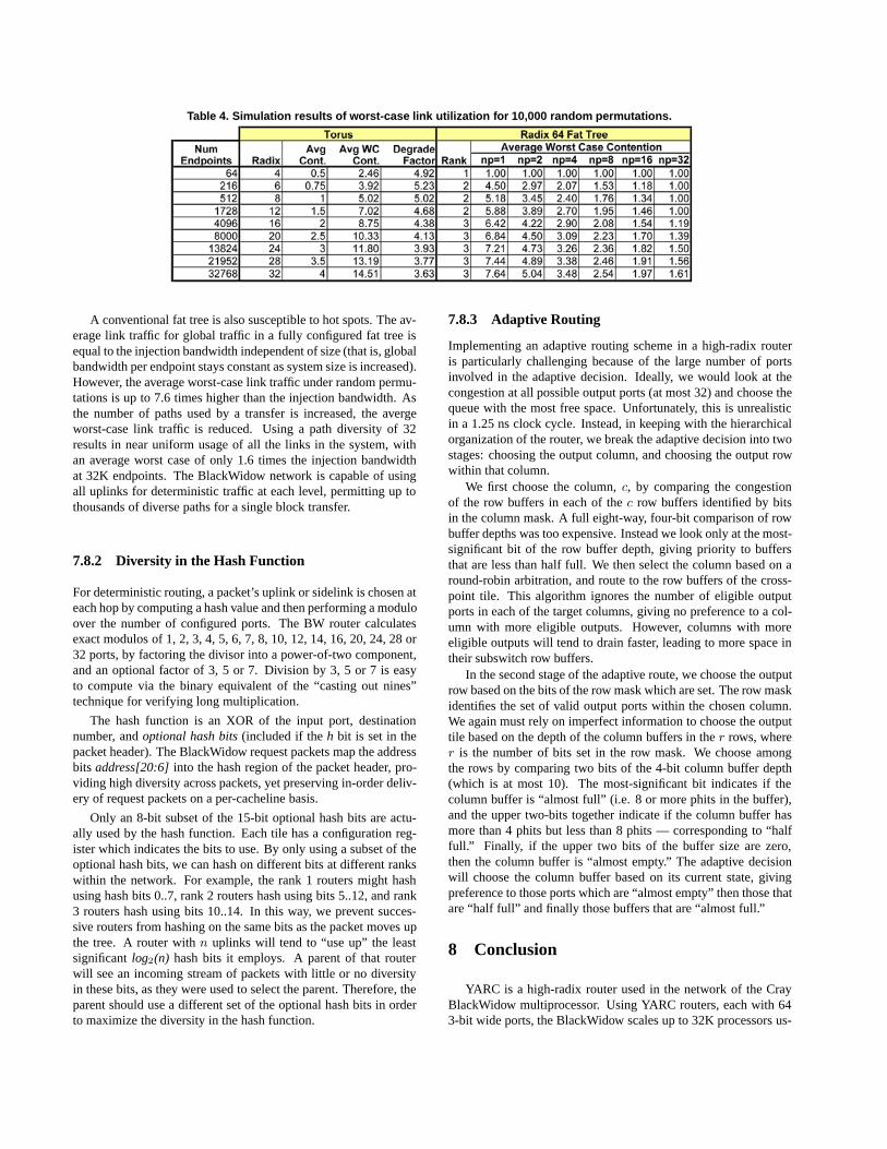
Table 4. Simulation results of worst-case link utilization for 10,000 random permutations.
A conventional fat tree is also susceptible to hot spots. The av-erage link traffic for global traffic in a fully configured fat tree isequal to the injection bandwidth independent of size (that is, globalbandwidth per endpoint stays constant as system size is increased).However, the average worst-case link traffic under random permu-tations is up to 7.6 times higher than the injection bandwidth. Asthe number of paths used by a transfer is increased, the avergeworst-case link traffic is reduced. Using a path diversity of 32results in near uniform usage of all the links in the system, withan average worst case of only 1.6 times the injection bandwidthat 32K endpoints. The BlackWidow network is capable of usingall uplinks for deterministic traffic at each level, permitting up tothousands of diverse paths for a single block transfer.
7.8.2 Diversity in the Hash Function
For deterministic routing, a packet’s uplink or sidelink is chosen ateach hop by computing a hash value and then performing a moduloover the number of configured ports. The BW router calculatesexact modulos of 1, 2, 3, 4, 5, 6, 7, 8, 10, 12, 14, 16, 20, 24, 28 or32 ports, by factoring the divisor into a power-of-two component,and an optional factor of 3, 5 or 7. Division by 3, 5 or 7 is easyto compute via the binary equivalent of the “casting out nines”technique for verifying long multiplication.
The hash function is an XOR of the input port, destinationnumber, and optional hash bits (included if the h bit is set in thepacket header). The BlackWidow request packets map the addressbits address[20:6] into the hash region of the packet header, pro-viding high diversity across packets, yet preserving in-order deliv-ery of request packets on a per-cacheline basis.
Only an 8-bit subset of the 15-bit optional hash bits are actu-ally used by the hash function. Each tile has a configuration reg-ister which indicates the bits to use. By only using a subset of theoptional hash bits, we can hash on different bits at different rankswithin the network. For example, the rank 1 routers might hashusing hash bits 0..7, rank 2 routers hash using bits 5..12, and rank3 routers hash using bits 10..14. In this way, we prevent succes-sive routers from hashing on the same bits as the packet moves upthe tree. A router with n uplinks will tend to “use up” the leastsignificant log2(n) hash bits it employs. A parent of that routerwill see an incoming stream of packets with little or no diversityin these bits, as they were used to select the parent. Therefore, theparent should use a different set of the optional hash bits in orderto maximize the diversity in the hash function.
7.8.3 Adaptive Routing
Implementing an adaptive routing scheme in a high-radix routeris particularly challenging because of the large number of portsinvolved in the adaptive decision. Ideally, we would look at thecongestion at all possible output ports (at most 32) and choose thequeue with the most free space. Unfortunately, this is unrealisticin a 1.25 ns clock cycle. Instead, in keeping with the hierarchicalorganization of the router, we break the adaptive decision into twostages: choosing the output column, and choosing the output rowwithin that column.
We first choose the column, c, by comparing the congestionof the row buffers in each of the c row buffers identified by bitsin the column mask. A full eight-way, four-bit comparison of rowbuffer depths was too expensive. Instead we look only at the most-significant bit of the row buffer depth, giving priority to buffersthat are less than half full. We then select the column based on around-robin arbitration, and route to the row buffers of the cross-point tile. This algorithm ignores the number of eligible outputports in each of the target columns, giving no preference to a col-umn with more eligible outputs. However, columns with moreeligible outputs will tend to drain faster, leading to more space intheir subswitch row buffers.
In the second stage of the adaptive route, we choose the outputrow based on the bits of the row mask which are set. The row maskidentifies the set of valid output ports within the chosen column.We again must rely on imperfect information to choose the outputtile based on the depth of the column buffers in the r rows, wherer is the number of bits set in the row mask. We choose amongthe rows by comparing two bits of the 4-bit column buffer depth(which is at most 10). The most-significant bit indicates if thecolumn buffer is “almost full” (i.e. 8 or more phits in the buffer),and the upper two-bits together indicate if the column buffer hasmore than 4 phits but less than 8 phits — corresponding to “halffull.” Finally, if the upper two bits of the buffer size are zero,then the column buffer is “almost empty.” The adaptive decisionwill choose the column buffer based on its current state, givingpreference to those ports which are “almost empty” then those thatare “half full” and finally those buffers that are “almost full.”
8 Conclusion
YARC is a high-radix router used in the network of the CrayBlackWidow multiprocessor. Using YARC routers, each with 643-bit wide ports, the BlackWidow scales up to 32K processors us-
ing a folded-Clos topology with a worst-case diameter of sevenhops. Each YARC router has an aggregate bandwidth of 2.4Tb/sand a 32K-processor BlackWidow system has a bisection band-width of 2.5Pb/s.
YARC uses a hierarchical organization[13] to overcome thequadratic scaling of conventional input-buffered routers. A two-level hierarchy is organized as an 8×8 array of tiles. This orga-nization simplifies arbitration with a minimal loss in performance.The tiled organization also resulted in a modular design that couldbe implemented in a short period of time.
The architecture of YARC is strongly influenced by the con-straints of modern ASIC technology. YARC takes advantage ofabundant on-chip wiring to provide separate column buses fromeach subswitch to each output port, greatly simplifying output ar-bitration. To operate using limited on-chip buffering, YARC useswormhole flow control internally while using virtual-cut-throughflow control over external channels.
To reduce the cost and the latency of the network, BlackWidowuses a folded-Clos network that is modified by adding sidelinksthat connect peer subtrees and statically partition the global net-work bandwidth. We showed the benefits of high-radix Clos, com-pared to the previous torus networks, in terms of fault tolerance,bandwidth spreading, and simpler routing algorithm. Both adap-tive and deterministic routing algorithms are implemented in thenetwork to provide load-balancing across the network and stillmaintain ordering on memory requests. Deterministic routing isperformed using a robust hash function to obliviously balance loadwhile maintaining ordering on a cache line basis.
As more networks take advantage of high-radix routers, manyopportunities are open for further research on high-radix routersand networks. High-radix Clos network can exploit high-radixrouters. However they are far from the lower bounds of achiev-able cost and latency. Research on alternate topologies may dis-cover more efficient organizations. The large number of possibleoutput ports on a high-radix router motivates the development ofnew routing algorithms. Of particular interest are algorithms thatreduce the complexity of the routing decision - to avoid quadraticscaling of the routing function. Research on router microarchitec-ture and switch organization is also of interest. As wire delays be-come more critical, organizations that exploit locality, for examplethose based on a network-on-chip may provide reduced latency.
Acknowledgements
Many people contributed to the development of the YARCrouter and BlackWidow network. Foremost, we would like tothank Greg Hubbard, Roger Bethard and Kelly Marquardt for theircountless whiteboard discussions. We would also like to thankthe rest of the BW network team: Joe Kopnick, Jack Webber,Boone Severson, Greg Faanes, Brad Smith, Doug Carlson, andPaul Wildes. We also thank Amit Gupta for his helpful insightsin the preliminary stages of this paper. Finally, we would like tothank three of the five referees for their detailed suggestions andcomments.
References
[1] J. Beecroft, D. Addison, F. Petrini, and M. McLaren.Quadrics QsNet II: A Network for Supercomputing Appli-cations. In Hot Chips 15, Stanford, CA, August 2003.
[2] C. Clos. A Study of Non-Blocking Switching Networks. TheBell System technical Journal, 32(2):406–424, March 1953.
[3] Cray X1. http://www.cray.com/products/x1/.[4] Cray XD1. http://www.cray.com/products/xd1/.[5] Cray XT3. http://www.cray.com/products/xt3/.[6] W. J. Dally. Performance Analysis of k-ary n-cube Inter-
connection Networks. IEEE Transactions on Computers,39(6):775–785, 1990.
[7] W. J. Dally. Virtual-channel Flow Control. IEEE Trans-actions on Parallel and Distributed Systems, 3(2):194–205,1992.
[8] W. J. Dally and C. L. Seitz. Deadlock-free message rout-ing in multiprocessor interconnection networks. IEEE Trans.Comput., 36(5):547–553, 1987.
[9] W. J. Dally and B. Towles. Principles and Practices of In-terconnection Networks. Morgan Kaufmann, San Francisco,CA, 2004.
[10] C. J. Glass and L. M. Ni. The turn model for adaptive routing.In ISCA ’92: Proceedings of the 19th annual internationalsymposium on Computer architecture, pages 278–287, 1992.
[11] M. J. Karol, M. G. Hluchyj, and S. P. Morgan. Input versusOutput Queueing on a Space-division Packet Switch. IEEETransactions on Communications, COM-35(12):1347–1356,1987.
[12] P. Kermani and L. Kleinrock. Virtual cut-through: A newcomputer communication switching technique. ComputerNetworks, 3:267–286, 1979.
[13] J. Kim, W. J. Dally, B. Towles, and A. K. Gupta. Microarchi-tecture of a high-radix router. In ISCA ’05: Proceedings ofthe 32nd Annual International Symposium on Computer Ar-chitecture, pages 420–431, Madison, WI, USA, 2005. IEEEComputer Society.
[14] J. Laudon and D. Lenoski. The SGI Origin: A ccNUMAHighly Scalable Server. In Proc. of the 24th Annual Int’lSymp. on Computer Architecture, pages 241–251, 1997.
[15] C. Leiserson. Fat-trees: Universal networks for hardwareefficient supercomputing. IEEE Transactions on Computer,C-34(10):892–901, October 1985.
[16] C. E. Leiserson, Z. S. Abuhamdeh, D. C. Douglas, C. R.Feynman, M. N. Ganmukhi, J. V. Hill, W. D. Hillis, B. C.Kuszmaul, M. A. S. Pierre, D. S. Wells, M. C. Wong-Chan,S.-W. Yang, and R. Zak. The Network Architecture of theConnection Machine CM-5. J. Parallel Distrib. Comput.,33(2):145–158, 1996.
[17] Mellanox. http://www.mellanox.com.[18] S. Mukherjee, P. Bannon, S. Lang, A. Spink, and D. Webb.
The Alpha 21364 network architecture. In Hot Chips 9,pages 113–117, Stanford, CA, August 2001.
[19] Myrinet. http://www.myricom.com/myrinet/overview/.[20] S. Scott and G. Thorson. The Cray T3E Network: Adaptive
Routing in a High Performance 3D Torus. In Hot Intercon-nects 4, Stanford, CA, Aug. 1996.
[21] A. Singh. Load-Balanced Routing in Interconnection Net-works. PhD thesis, Stanford University, 2005.
[22] C. B. Stunkel, D. G. Shea, B. Aball, M. G. Atkins, C. A.Bender, D. G. Grice, P. Hochschild, D. J. Joseph, B. J.Nathanson, R. A. Swetz, R. F. Stucke, M. Tsao, and P. R.Varker. The SP2 High-performance Switch. IBM Syst. J.,34(2):185–204, 1995.
[23] Texas Instruments - SR50. http://www.ti.com/.