
The Behaviour of Beam-C olumn Elements with Variable I...
15
1 Abstract Steel structural elements with variable cross section, made of welded plates, are largely used in the construction industry for both beams and columns in accordance with the stress and stiffness demand in the structure. These types of elements are mainly used for the design of singles storey frames with pitched roof rafters and pinned column base. Rafters and columns can be designed as tapered members made of steel welded plates, respecting the bending moment diagrams for gravitational load combination. Although they are partially restrained against out of plane buckling by side-rails and roof purlins cooperating with sheeting, in current design practice it is quite difficult to evaluate their influence. This paper deals with nonlinear elastic-plastic analysis and experimental tests performed on tapered beam-columns, parts of portal frames, subjected to both bending moment and compressive axial force. Failure of such members may occur by in-plane bending, local buckling and combination between these two, for members with low non-dimensional slenderness. While for members with intermediate and high non-dimensional slenderness, flexural–torsional buckling, local buckling and combination of these two may occur in function of the web slenderness. Numerical results will be compared with experimental tests, obtained for a relevant number of specimens, in order to check the reliability of the numerically determined ultimate capacity of the elements. The influence of both lateral and torsional restraints applied on the beam-column will also be discussed. Keywords: welded plates element, tapered members, pitched roof frames, out of plane buckling. Paper 3 The Behaviour of Beam-Column Elements with Variable I Cross-Sections considering Lateral Restraints I.M. Cristutiu 1 and A.I. Dogariu 2 1 Faculty of Architecture 2 Faculty of Civil Engineering “Politehnica” University of Timisoara, Romania ©Civil-Comp Press, 2012 Proceedings of the Eleventh International Conference on Computational Structures Technology, B.H.V. Topping, (Editor), Civil-Comp Press, Stirlingshire, Scotland
-
Upload
truonghanh -
Category
Documents
-
view
216 -
download
0
Transcript of The Behaviour of Beam-C olumn Elements with Variable I...
1
Abstract Steel structural elements with variable cross section, made of welded plates, are largely used in the construction industry for both beams and columns in accordance with the stress and stiffness demand in the structure. These types of elements are mainly used for the design of singles storey frames with pitched roof rafters and pinned column base. Rafters and columns can be designed as tapered members made of steel welded plates, respecting the bending moment diagrams for gravitational load combination. Although they are partially restrained against out of plane buckling by side-rails and roof purlins cooperating with sheeting, in current design practice it is quite difficult to evaluate their influence. This paper deals with nonlinear elastic-plastic analysis and experimental tests performed on tapered beam-columns, parts of portal frames, subjected to both bending moment and compressive axial force. Failure of such members may occur by in-plane bending, local buckling and combination between these two, for members with low non-dimensional slenderness. While for members with intermediate and high non-dimensional slenderness, flexural–torsional buckling, local buckling and combination of these two may occur in function of the web slenderness. Numerical results will be compared with experimental tests, obtained for a relevant number of specimens, in order to check the reliability of the numerically determined ultimate capacity of the elements. The influence of both lateral and torsional restraints applied on the beam-column will also be discussed. Keywords: welded plates element, tapered members, pitched roof frames, out of plane buckling.
Paper 3 The Behaviour of Beam-Column Elements with Variable I Cross-Sections considering Lateral Restraints I.M. Cristutiu1 and A.I. Dogariu2 1 Faculty of Architecture 2 Faculty of Civil Engineering “Politehnica” University of Timisoara, Romania
©Civil-Comp Press, 2012 Proceedings of the Eleventh International Conference on Computational Structures Technology, B.H.V. Topping, (Editor), Civil-Comp Press, Stirlingshire, Scotland

2
1 Introduction Structural stability is the fundamental security criterion for buildings, both during their functioning period and construction lifetime. The current European standard EN 1993-1-1[1], contains numerical procedures for buckling verification of steel structural elements, which differ from the traditional simplified procedures. The latter only covered regular geometrical shapes, simple load cases and classical supports (rigid or pinned). Nowadays advanced numerical computer-aided analyses can be performed which allow the investigation of complex structures by using European provisions. This allows one to use a greater number of factors that affect the structure in what concerns their stability: geometrical imperfections, material nonlinearities, production residual stresses, element lateral restraining, and real element boundary conditions. Although, the actual standards are more complex than the previous ones, interaction formulas for the strength and buckling verification of individual elements for different type of load (e.g. tension, compression, bending, shear, twisting, and combination between them) are provided only for uniform members. There are some provisions that could be applied for the design of tapered members, namely ―the general method. However its application involves advanced structural analysis (e.g. linear eigen buckling and elasto-plastic analysis).
Single storey buildings and not only, possess a steel main frame usually made of welded plate elements with tapered web classified as class 3 (elastic) and 4 (slender) according to EN 1993-1-1[1]. The constituent elements are mainly subjected to bending moment and interaction between bending moment and compression. In the case of class 3 sections, when they are restrained against lateral or/and torsional buckling, the interaction between sectional plastic buckling and overall buckling of the members in compression and/or in bending is possible. When class 4 (slender) sections are used, which generally is the case of the rafter at the maximum height of the tapered web, the sectional buckling (e.g. local buckling of walls or distortion) may occur in the elastic domain. If no lateral restrains, or when they are not effective enough, the lateral torsional mode could characterize the global behaviour of the frame members or interaction with sectional bucking modes may occur as well. Tapering of the elements is made in accordance with internal force distribution under gravitational loads, which are predominant in the design of these types of structures.
Even though many researchers have performed investigation on the uniform elements subjected to bending moment and axial compression force [2,3,4], information regarding the out-of-plane behaviour of tapered elements is still limited. The ultimate capacity for tapered steel plate girders subjected to shear was determined by Shanmugam [5] and the one for axially loaded thin-walled tapered columns with doubly symmetric sections by Salem [6]. Shanmugam [5] experimentally determined the ultimate behaviour of tapered steel plate girders and concluded that the shear capacity of the girder is 5% less than in the case of the prismatic one, if the inclined flange is tensioned. Whilst inclined flange is subjected to compression, the ultimate load of the tapered girder increases by more than 5% compared to that of straight girders.
3
The aim of the present paper is to analyse numerically and analytically the tapered beam-columns, parts of portal frames, subjected to a major axis bending moment and a compression axial force. Main failure mode of such members is likely to occur by in-plane bending, local buckling and yielding for members with short lengths, and by flexural–torsional buckling, local buckling and yielding at members with intermediate and long lengths. 2 Finite element model 2.1 Description of the model It is generally known that experimental tests are both time and labour consuming. However, if the boundary conditions and applied forces are not adequately provided, the final results of the experimental test could be altered significantly. The finite element modelling is a powerful tool that would be an alternative for the experimental test regarding the analysis of the behaviour and in establishing the ultimate capacity of steel structural elements. For the purpose of the present work some finite element models were built. Numerical simulations were performed in accordance with EN 1993-1-5 Annex C[7] that gives guidance for the use of FE-methods in order to evaluate the ultimate capacity. The commercial finite element package Abaqus v6.5-1 has been used. This software has proven its reliability in many benchmark studies and was considered suitable for the current task.
A finite element model was built using shell and solid elements following the exact nominal geometrical dimensions of tapered members. Shell elements were used mainly for the modelling of the straight parts, whilst solid elements were considered for the modelling of the connections. Consequently a three dimensional model was obtained whereon real test boundary conditions were applied (see figure 1). Two different cases i.e: end warping free (WF) and restrained warping (WR) were considered.
Using this complex model geometrical and material nonlinear analysis were performed on the perfect element (i.e GMNA). A four and three node, quadrilateral and triangular shape of linear geometric order, S4R, respective S3, finite elements were used. Both geometrically and materially nonlinear behaviour were considered, together with the equivalent global bow geometric imperfection, to determine elastic-plastic resistance in ULS, using GMNIA. Imperfections were applied according to EN1993-1-1 provisions, i.e. out of plane initial bow imperfection with the amplitude of 1/150 from the length of the considered elements, corresponding to a plastic analysis of a welded I-section element (buckling curve c about minor axis z-z). The considered equivalent imperfections take account for residual stresses and geometrical imperfections such as lack of verticality, lack of straightness, lack of flatness, lack of fit and any minor eccentricities present in the joints of the unloaded structure. Most of the standard provisions do not consider torsional imperfection (except AS4100 [8]) due to its small influence, hence no such imperfection were introduced in the analysis. Even if in some sections of the member (i.e. tapered section), class 4 of cross-section was obtained, the local sectional imperfection was

4
not considered individually, this being accounted in the considered equivalent imperfections. The material used is S355 steel grade with an elastic-perfectly plastic material behaviour.
a) (WF)
b) (WR)
Figure 1: Overall loading scheme and considered boundary conditions 2.2 Calibration of the FEM model 2.2.1 Description of the experimental test Finite element model was calibrated based on experimental test performed by Cristutiu et al [9].
A simple pitched-roof portal frame, as the one in Fig. 1, was designed at first in order to define realistic specimen configurations. The main geometric dimensions of the frame were: 12 m span, 6 m bay, 4 m height and a pitch roof angle α=80. Common load cases according to EN1991 [10,11] provisions were considered i.e: characteristic dead load of roof cladding gk=0.7 kN/m2; characteristic snow load sk=2.0 kN/m2. The load combination considered for the ultimate limit state was 1.35gk+1.5sk, and for the serviceability limit state was 1.0gk+1.0sk. The steel frame was analysed and designed according to the current EN 1993-1-1 provisions. The frames were considered pinned at the foundation level, while the rafter-to-column connection was considered fully rigid. The column specimens were extracted from the resulting frame and their global geometrical dimensions are presented in Fig. 2. In order to analyse the influence for the web thickness on the column behaviour, two different values (i.e. 6 and 8 mm) were considered. Three specimens of each configuration were tested, finally resulting in a number of six experimental tests.

5
The difference between the tests, for each specimen, was the provided type of lateral restraints.
A- AA
A
bb
w
t =20 mm
p
p
B - B
1
h 2
t =10mm
t =15 mm
h 1
h 2
f
t =10mmf
t =6...8mm
3393
20 3376 15
5040
h
B
B
Figure 2. Tested specimen typology
Specimen L
[mm] h1 [mm]
h2 [mm]
b tf tw
C1_8 3376 250 600 200 10 8 C2_6 3376 250 600 200 10 6
Table 1. Specimen main dimension Three of the specimens had 8 mm tapered web (C1-8) and the other three were designed with 6 mm tapered web (C2-6). The types of lateral restraints considered for each specimen configuration were (see Figure 3): (NR) – no restraints, (LR) – lateral restraints; and (TR) – torsional restraints respectively. Lateral restraints (LR) were provided by thin walled cold formed ―Zed purlins (Z150/1.5 mm), while in the case of torsional restraints (TR) supplementary L50x50x5 fly braces were provided at the compressed flange.
Figure 3: Types of lateral restraints
The applied static scheme was a simple one, i.e. pinned connection at the right
end of the column, and a mobile pin at the bottom of the vertical column. The vertical column was designed stiff enough, not to suffer any important deformation during test. A horizontal force was applied at the end of the vertical column. The applied load and boundary conditions were designed in such a way to load the
6
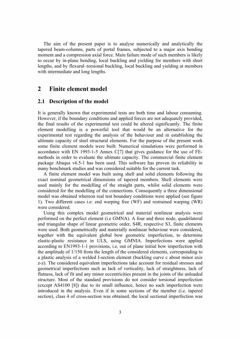
column by a combination between axial load and bending moment (Figure 5). The testing set-up was constructed in such a way to replace only the specimen from one test to the other. The load was applied through a Quiri hydraulic jack, with a maximum capacity of 1000 kN.
Figure 4. Testing setup and loading scheme
The tests have been conducted in displacement control procedure. Load was
applied quasi-statically with a displacement velocity of 3.33 mm/min. Overall view of the test setup is presented in Figure 4. Lateral restraints were applied at the top of the vertical column, to avoid out of plane displacement due to inherent imperfection. The in plane and out of plane displacement was monitored during tests through a number of 18 Novotechnic displacement transducers. Some of them measuring absolute displacement of the indicated points related to points independent from the testing frame (e.g: D1,D3…D9), whilst some of the relative displacement between points located on the tested frame (e.g: D2f,b). 2.2.2 Results of experimental test vs FEM A number of six tests have been performed on the specimens with the lateral restraints presented in Figure 3. Three of the specimen had 8 mm tapered web (C1-8) and the other three were designed with 6 mm tapered web (C2-6). The results obtained from experimental test and finite element modelling is presented herein in the forms of tables and graphs. The Moment rotation curve plot in figures show the behaviour from the elastic to ultimate capacity of the tapered columns laterally restrained or not. Von Misses stress distribution at the levels of flange and web are given to emphasize how the yielding zones develops according to increased load. Experimentally moment-rotation curves are compared with those obtained from the finite element analysis to verify both the accuracy of the finite element model and experimental test. A triliniar behaviour curve of the material was considered in the finite element modelling. The inflection points on the material behaviour curs represent the yield strength-fy and the ultimate strength fu respectively. The measured values of stresses from the tensile test were considered in the analyses.
7
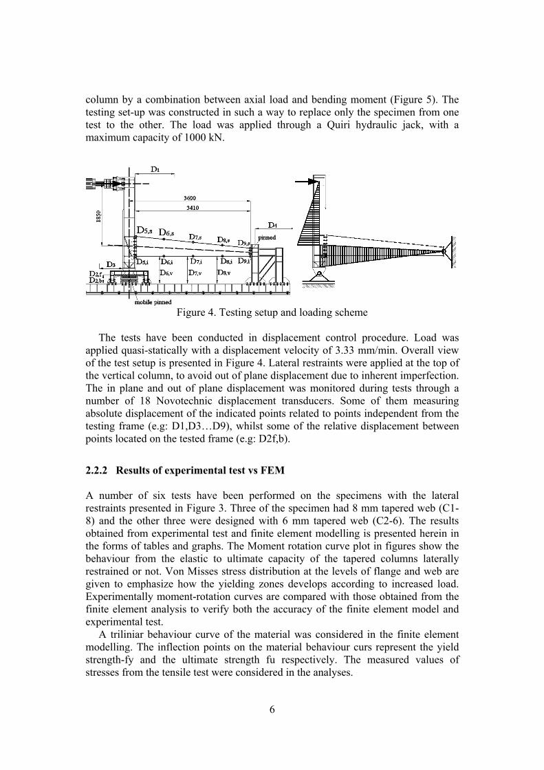
Experimental bending moment within the specimen with the corresponding values obtained from the finite element analysis is summarized in Table 2 for all the tested specimens. In the table MFEM refers to the finite element results, MEXP to the experimental tests. The moment-rotation curve obtained from test and FEM are plotted in Figure 5 for the series of C1-8 test and in Figure 6 for the series of C2-6 respectively.
Specimen MFEM
[kNm] MEXP [kNm]
C1_8_NR 474.51 488.75C1_8_LR 491.91 485.79C1_8_TR 527.09 534.44C2_6_NR 388.04 395.75C2_6_LR 395.93 382.43C2_6_TR 394.82 386.19
Table 2. Summarized bending moment capacities, FEM- experimental
Figure 5. Results on C1_8 series specimens
Failures of the specimen recorded during experimental tests are illustrated in
Figure 5 for different lateral restraints of C1-8 series specimens whilst the one recorded for C2-6 specimens are illustrated in Figure 6. It can be emphasized that for the case of C1-8 series, the failure is significantly influenced by the type of the lateral restraints. Although the same influence of the lateral restraints should have been recorded in case of C2-6 series, the obtained results did not confirm it. For the later the lateral restraints had a reduced influence both from the behaviour point of

8
view and failure mode (i.e. distortion of the compressed flange coupled with a local buckling of the column).
The failure modes of the C1-8 series of testes can be described as: C1_8_NR – at the beginning distortion of the compressed flange, followed by overall lateral-torsional buckling of the column; C1_8_LR – at the beginning distortion of the compressed flange, followed by overall lateral-torsional buckling of the column; C1_8_TR – distortion of the compressed flange followed by a slight overall torsional buckling.
The failure modes of the C1-6 series of testes can be described as: C1_6_NR – starting with distortion of the compressed flange, followed by slight isolated sectional buckling and overall lateral-torsional buckling of the column; C1_6_LR and C1_6_TR – starting with distortion of the compressed flange, followed by slight isolated sectional buckling and overall lateral-torsional buckling of the column. The isolated sectional buckling for this series of tests prevails over the global out of plane buckling.
Figure 6. Results on C2_6 series specimens
Von Misses stress distribution at the levels of flange and web are given to
emphasize how the yielding zones develops according to increased load. Experimentally Moment-rotation curves as compared with those obtained from the finite element analysis to verify both the accuracy of the finite element model and experimental test.
Views at the at the ultimate capacity loading of the considered specimens are shown along with the corresponding finite element predictions Figure 5 and Figure 6. Generally a good arrangement can be observed between the deflected web parts

9
and those obtained from finite element analysis. Similar observation could also be made in respect of deformations in flanges.
3 Analysed members and methods of analysis 3.1 Evaluation of the ultimate capacity The European norm EN1993-1-1 gives no detailed information and rules regarding the non-uniform members design capacity determination, except of general method based on rather advanced finite element simulations and an unclear way to establish the appropriate reduction factor depending on buckling curves and imperfections.
For design tapered members, three main approaches are possible: a first one is based only on the hand calculations using formulas, a second one that combines simple computer calculations with formulas, and a third one that consist in a complete computer calculation.
The first approach is based on analytical formulas available in the scientific papers to determine the bifurcation loads, i.e. elastic critical moment for lateral torsional buckling Mcr (either considering an equivalent section or by computing the flexural buckling of the compressed flange) and elastic critical axial force for flexural buckling Ncr. The imperfection sensitivity, elastic plastic interaction and interaction between different stress components will be considered using EN1993-1-1 provisions.
A standard FEM program ABAQUS has been used for estimation elastic critical resistance Rcr and plastic reference resistance Rpl, to be used at the determination of the design elastic-plastic buckling resistance Rd with the general method. The reduction factor χov, that consider both lateral and lateral-torsional buckling, will be determined as minimum and as an interpolated value of reduction factors for flexural and lateral-torsional buckling. The bending and compression effects will be consider separately, and after combined by applying the interaction factors, or by the simultaneous action of both bending moment and axial force. In this method imperfection sensitivity and elastic plastic interaction must be taken from the code provision. 3.2 Analysed cases In order to optimize the material costs of the pined portal frame industrial building with the span L in range of 12-30 m and a Lc column height of 4-6m, tapered member made of steel welded plates, respecting the bending moment diagrams, are widely used in constructional practice. At first the frames described above and presented in Figure 7 were designed to withstand gravitational load and to fulfil the ultimate limit state (ULS) and serviceability limit state (SLS) according to EN1993-1-1. The column specimens were extracted from the resulting frame and their global geometrical dimensions are presented in Table 3. In Table 3 design axial force (NEd) and design bending moment (MEd), resulted under gravitational load combination, are presented as well.

10
Figure 7. Analysedframes
L x h 12x4 12x5 12x6 15x4 15x5 15x6 18x4 18x5 18x6 20x4
20x5 20x6
Hmax 600 550 550 650 650 650 700 650 700 750 750 750 Hmin 250 250 250 300 300 300 350 350 350 350 350 350 B 200 220 220 220 220 240 250 240 260 240 250 270 tf 10 10 12 12 12 12 12 14 14 14 14 14 tw 8 8 8 8 8 8 10 10 10 10 10 10 NEd 143 121 124 170 139 138 214 180 183 227 186 186 MEd 270 221 225 413 345 350 582 486 500 714 602 607 L x h 22x4 22x5 22x6 24x4 24x5 24x6 27x4 27x5 27x6 30x4 30x5 30x6 Hmax 800 800 800 850 850 850 950 950 950 1050 1050 1050 Hmin 350 350 350 350 350 350 400 400 400 450 450 450 B 260 260 290 270 270 300 290 290 320 3110 310 340 tf 14 14 14 14 14 14 14 14 14 14 14 14 tw 10 10 10 10 10 10 12 12 12 12 12 12 NEd 262 219 222 267 227 227 324 272 274 350 289 289 MEd 842 708 729 950 829 842 1247 1053 1070 1505 1293 1328
Table 3. Geometric dimensions of the analysed cases
For the models presented in the Table 3, eigen-buckling analyses were performed, in order to identify their elastic failure in function of different type of lateral restraints and applied load (axial force, or bending moment). The first 50 modes were evaluated for each of them. The following failure mode were monitored: lateral buckling (LB); torsional buckling (TB); lateral torsional buckling (LTB) and local buckling (EBP).
Both eigen-buckling (LEA) and nonlinear elastic-plastic (GMNIA) analyses had been applied [7]. The computation was performed with Abaqus 6.4 FEM program using Shell elements enabling for large plastic deformation. The material behaviour was introduced by a bilinear elastic-perfectly plastic model, while S355 yield strength was considered in the analysis. Lateral restrains by purlins were considered. The lateral restraints are of 4 different types, as shown in Figure 8. Types 2 and 3 simulate the purlin/sheeting effect, when the purlin can be connected with one or two bolts, respectively. Type 4 is type 2 with an additional fly brace. Type 1, the reference case, actually means no lateral restrains introduced by purlins. To simplify the computational model, in the analysis the lateral restrains had been considered axially rigid.

11
a) NR
b)LR1
c)LR2
d)TR
Figure 8. Type of lateral restraints
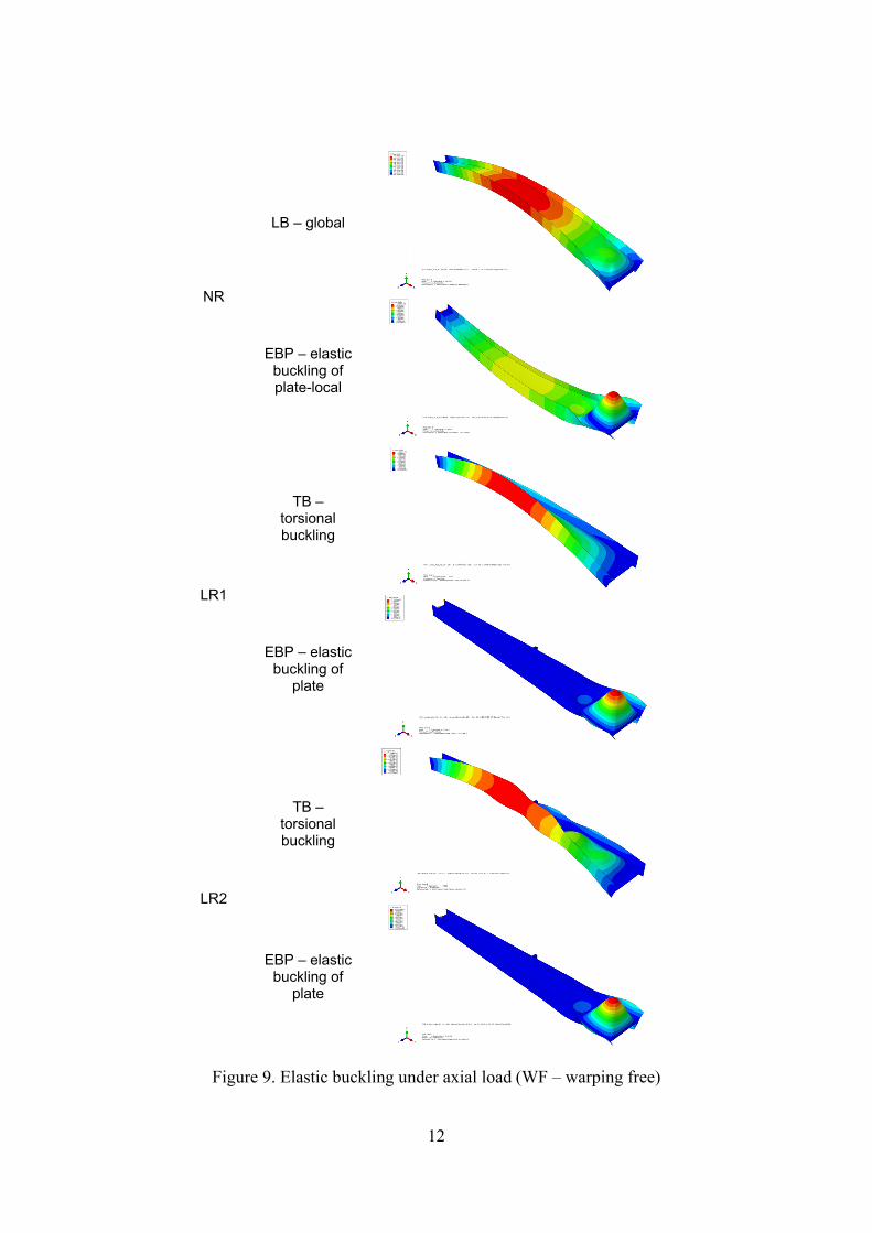
3.2 Results of numerical analysis Linear eigen-buckling analysis (LEA) and geometrically-materially nonlinear analysis with imperfections (GMNIA) were performed to identify the critical modes of members and the elastic plastic-failure of the considered tapered members. The LEA analysis was performed separately for axially loaded elements and for pure bending. Hence the critical buckling load Ncr (used for evaluation of the lateral buckling strength) and critical moment Mcr (used for evaluation of the torsional buckling strength) were determined for all the considered cases. Due to lack of space herein only the case of 12 m span and 4,5,6 m height will be discussed. The results in terms of behaviour were similar for all the considered cases. These were determined for all types of lateral restraints. Figure 9 and 10 show members in failure under axial load and pure bending for WF cases (see Figure 1).
12
NR
LB – global
EBP – elastic buckling of plate-local
LR1
TB – torsional buckling
EBP – elastic buckling of
plate
LR2
TB – torsional buckling
EBP – elastic buckling of
plate
Figure 9. Elastic buckling under axial load (WF – warping free)
13
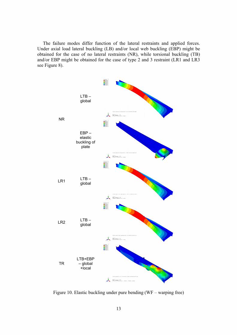
The failure modes differ function of the lateral restraints and applied forces. Under axial load lateral buckling (LB) and/or local web buckling (EBP) might be obtained for the case of no lateral restraints (NR), while torsional buckling (TB) and/or EBP might be obtained for the case of type 2 and 3 restraint (LR1 and LR3 see Figure 8).
NR
LTB – global
EBP – elastic
buckling of plate
LR1 LTB – global
LR2 LTB – global
TR LTB+EBP – global +local
Figure 10. Elastic buckling under pure bending (WF – warping free)

14
Under pure bending lateral torsional buckling (LTB) and/or EBP is obtained for the case of no lateral restraints (NR), global lateral torsional buckling (LTB) for type 2 and 3 lateral restraints (LR1 and LR2), while coupling of LTB and EBP might appear for the case of torsional restraints (TR).
For the case of 12 m span and 4,5,6 m height, supplementary eigen-buckling analyses and elasto-plastic analyses were performed. These were necessary for the evaluation of the ultimate capacity of the members via the “general method” (GM) of EN1993-1-1[1], thus obtaining rGM (load factor of the design action). The load factor corresponding for the GMNIA analysis, rGMNIA, was determined as well. Table 4 shows the results and comparisons with the “general method”.
12 m frame with height of αu αcr χGM rGM rGMNIA
4 2.44 4.4701 0.618 1.508 1.490 5 2.83 4.5417 0.586 1.658 1.838 6 3.13 3.801 0.517 1.618 1.790
Table 4. Comparison between GM and GMNIA
Analysing the results presented in Table 4, we can say that the results of the “general method” are rather conservative, the difference ranging around 10% with a slight exception for the case of 4 m height where an unsafe result was obtained. The latter could be explained by possible local buckling of the web, instead of global out of plane buckling. 4 Conclusions An extensive finite element study of the behaviour and load carrying capacity of tapered web beam-columns have been presented in the present work. At first the finite element models were calibrated using results of an experimental test made by the authors. A number of six specimens with different web thicknesses and lateral restraints were tested. For these cases the web slenderness is quite significant, while the global slenderness is rather low and hence the failure was dominated mainly by local modes.
Based on the results presented within this paper, it can be concluded that the finite element modelling is reliable in predicting the ultimate capacity of the elements with tapered web under both compression and bending with sufficient accuracy.
The failure mechanism for the selected specimen series varies in function of the web thickness and lateral restraints (i.e. global out of plane buckling governs in the case of thicker web specimens, whilst distortion of the compressed flange and local web buckling for the case of most slender webs). The ultimate capacity is significantly influenced by the width/thickness ratio of the web.
The failure mode varies between local and global buckling as a function of the applied lateral restraints.

15
Acknowledgements The authors gratefully acknowledge the financial support of “National University Research Council – NURC-CNCSIS-Romania” through the national research grant PN-II-RU-TE-2010-1/38 References [1] EN 1993-1-1, “Eurocode 3 ―Design of steel structures Part 1.1: General rules
and rules for buildings”, CEN - CEN - Brussels, Belgium 2005. [2] A. Taras, and R Greiner, “Torsional and flexural torsional buckling — A study
on laterally restrained I-sections”, Journal of constructional steel research, 64 (2008) 7-8, S. 725 – 731, 2008.
[3] J.Szalai and F.Papp, “On the probabilistic evaluation of the stability resistance of steel columns and beams”, Journal of Constructional Steel Research, 65 (2009), 569-577,2009.
[4] B. Farshi and F. Kooshesh, “Buckling Analysis of structural steel frames with inelastic effects according to codes”, Journal of constructional steel research, 65 (2009), 2078-2085, 2009.
[5] N.E Shanmugam and H. Min, “Ultimate load behaviour of tapered steel plate girders”. Steel and Composite Structures, 7(6), 469-486, 2007.
[6] A.H. Salem, M. El Aghoury, M.N. Fayed, I.M. El Aghoury, ”Ultimate capacity of axially loaded thin-walled tapered column with doubly symmetric sections”. Thin Walled Structures, 47(2009), 931-941,2009.
[7] EN 1993-1-5, “Eurocode 3 (2003) ―Design of steel structures Part 1.5: Plated structural elements”, CEN - CEN - Brussels, Belgium 2003.
[8] AS 4100—1998. Australian Standard: Steel Structures. Australian Building Codes Board.
[9] I.M Cristutiu, D.Nunes and A. Dogariu “Experimental study on laterally restrained steel columns with variable I cross sections”, in “ Proceedings of the International Conference on Steel and Composite Structures”, C.K.Choi (Editor), Seoul, Korea, 2011.
[10] EN 1991-1-1 Eurocode 1 (2002) ―Actions on structures - Part 1-1: General actions - Densities, self-weight, imposed loads for buildings�, CEN - CEN - Brussels, Belgium 2002.
[11] EN 1991-1-1 Eurocode 1 (2003) ―Eurocode 1 - Actions on structures - Part 1-3: General actions -Snow loads�, CEN - CEN - Brussels, Belgium 2003.


![A Structural Health Monitoring System Based on an Analysis ...webapp.tudelft.nl/proceedings/cst2012/pdf/maczak.pdf · structural vibrations and temperature fluctuations [2]. Both](https://static.fdocuments.in/doc/165x107/5fec4f6e050a886324606899/a-structural-health-monitoring-system-based-on-an-analysis-structural-vibrations.jpg)

