The Ball Piston Engine
27
THE BALL PISTON ENGINE CONTENTS CONTENTS 01 ABSTRACT 02 INTRODUCTION 03 TYPES OF ENGINE 04 CONSTRUCTION OF MULTI ENERGY DOMAIN ENGINE 05 WORKING 06 IMPORTANT DESIGN FUTURES 07 CONSTRUCTION OF WANKLE TWO STROKE ROTATY BALL PISTON ENGINE 08 WORKING 09 OPERATION AND TIMING 10 LUBRICATIONS AND COOLING OF ENGINE 11 ADVANTAGES & DISADVANTAGES 12 APPLICATION 13 CONCLUSION G. P. WASHIM PAGE NO.1
-
Upload
rajesh-shyamrao-kaje -
Category
Documents
-
view
5.101 -
download
4
description
THE BALL PISTON ENGINE:The ball piston engine is a new concept in high efficiency power machine. Although the basic geometry was invented by individuals, the concept has been subsequently studied and developed by scientists and professional engineers.
Transcript of The Ball Piston Engine
THE BALL PISTON ENGINE
CONTENTSCONTENTS
01 ABSTRACT
02 INTRODUCTION
03 TYPES OF ENGINE
04 CONSTRUCTION OF MULTI ENERGY
DOMAIN ENGINE
05 WORKING
06 IMPORTANT DESIGN FUTURES
07 CONSTRUCTION OF WANKLE TWO
STROKE ROTATY BALL PISTON ENGINE
08 WORKING
09 OPERATION AND TIMING
10 LUBRICATIONS AND COOLING OF ENGINE
11 ADVANTAGES & DISADVANTAGES
12 APPLICATION
13 CONCLUSION
14 REFERENCES
G. P. WASHIM PAGE NO.1
THE BALL PISTON ENGINE
ABSTRACT
A Patented new power machine concept has been designed and analyzed
for production, and proof of principle sub scale tests have been performed,
with positive result. The machine design concept is applicable as a
compressor, pump, motor, or engine. Simplicity of design based on
spherical ball piston enable a low moving part count, high power to weight
ratio, elimination of valve train and water cooling systems, and perfect
dynamic balance.
The new design concept utilizes novel kinematic design to completely
eliminate inertial loads that would contribute to sliding friction. Also, low
leakage is maintained without piston rings by using a small clearance on
the ball piston, resulting in choked flow past the ball. These features
provide the potential for an engine with higher efficiency than
conventional piston engines. The engine design - utilizes existing recent
technology to advantage, such as silicon nitride ball pistons, so a large
development effort is not required.
G. P. WASHIM PAGE NO.2
THE BALL PISTON ENGINE
INTRODUCTION
The ball piston engine is a new concept in high efficiency power
machine. Although the basic geometry was invented by individuals, the
concept has been subsequently studied and developed by scientists and
professional engineers.
The machine concept is attributes to simplicity. Having only a small
number of moving parts, the design implements a modified version of the
tried and proven thermodynamic otto cycle when use as a engine. Although
the small parts count an important advantages, other than the ball piston
engine will give future engineers new- found freedom in tailoring the
combustion processes.
TYPES OF ENGINE
A multienergy domain engine (model)
Wankle to stroke rotary ball piston engine
G. P. WASHIM PAGE NO.3
THE BALL PISTON ENGINE
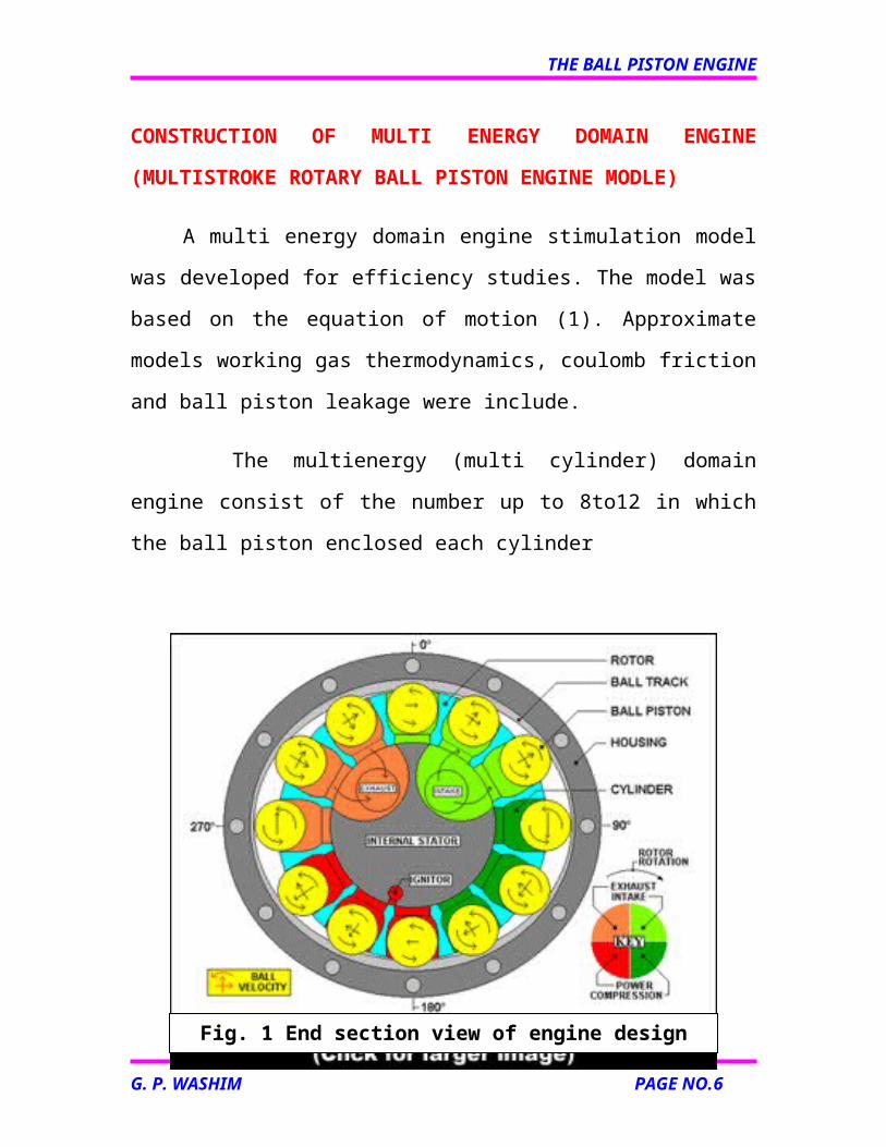
CONSTRUCTION OF MULTI ENERGY DOMAIN ENGINE
(MULTISTROKE ROTARY BALL PISTON ENGINE MODLE)
A multi energy domain engine stimulation model was developed for
efficiency studies. The model was based on the equation of motion (1).
Approximate models working gas thermodynamics, coulomb friction and
ball piston leakage were include.
The multienergy (multi cylinder) domain engine consist of the
number up to 8to12 in which the ball piston enclosed each cylinder
G. P. WASHIM PAGE NO.4
Fig. 1 End section view of engine design

THE BALL PISTON ENGINE
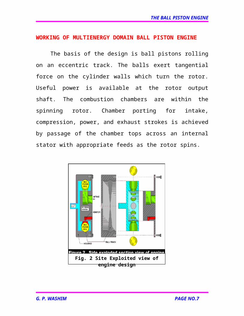
WORKING OF MULTIENERGY DOMAIN BALL PISTON ENGINE
The basis of the design is ball pistons rolling on an eccentric track.
The balls exert tangential force on the cylinder walls which turn the rotor.
Useful power is available at the rotor output shaft. The combustion
chambers are within the spinning rotor. Chamber porting for intake,
compression, power, and exhaust strokes is achieved by passage of the
chamber tops across an internal stator with appropriate feeds as the rotor
spins.
Beginning at top dead center (TDC) at 0 degrees rotation, the stator
intake passage is open to the cylinder and a fuel/air charge is pulled into the
cylinder as the ball piston moves radially outward for the first 90 degrees of
rotation (intake stroke).
Then the intake passage is closed off, and the ball reverses radial
direction for the next 90 of degrees of rotation, during which time the new
G. P. WASHIM PAGE NO.5
Fig. 2 Site Exploited view of engine design
THE BALL PISTON ENGINE
charge is compressed (compression stroke). Just past 180 degrees rotation,
the compressed charge is ignited as the cylinder port passes a small ignitor
port. Combustion ensues, and the high combustion pressure pushes radially
outward (on the ball piston for the next 90 degrees of rotation. The ball in
turn pushes tangentially on the cylinder wall because of the "slope" of the
eccentric ball track, which is now allowing the ball to move radially
outward. The tangential force produces useful torque on the rotor (power
stroke).
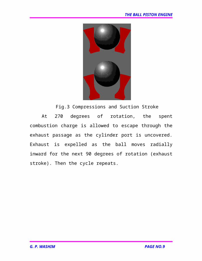
Fig.3 Compressions and Suction Stroke
At 270 degrees of rotation, the spent combustion charge is allowed to
escape through the exhaust passage as the cylinder port is uncovered.
Exhaust is expelled as the ball moves radially inward for the next 90 degrees
of rotation (exhaust stroke). Then the cycle repeats.
G. P. WASHIM PAGE NO.6
THE BALL PISTON ENGINE
IMPORTANT DESIGN FUTURES
The porting required for four stroke operation is achieved with
numbers of additional part, and no valve train losses. The porting
mechanism is achieved with simple port clocking within the
rotor/internal stator bearing interface. Thus part count is low and
hardware is simple in geometry, with only the rotor and ball piston as
moving part.
Sliding friction site are minimized by the use of a rolling ball piston.
Sliding friction still exists at the ball/cylinder wall contact, but it
minimized by special material selection and possibly local lubrication.
The use of an eccentric ball track allows tailoring of the chamber
volume vs time to optimize the cycle from a thermodynamic and
chemical kinetics stand point. The only requirement is that the ball
return to the starting radius at TDC before intake. For example
expansion/exhaust stroke length can be made different than for
intake/compression for more exhaust energy recovery, or the
combustion can be held at constant volume for a certain period.
Multicylinder rotor can be implemented. Instead of 4 stroke, 8,12 or
more stroke can be transverse in a single revolution. This effectively
multiplies the power out put proportionally if the stroke is maintain
constant.
The use of many ball pistons, which undergo the four strokes in
clocked fashion, result in smooth power delivery and small net
oscillatory forces, the total ball inertial forces are automatically
balanced by symmetry if numbers of ball is even.
G. P. WASHIM PAGE NO.7
THE BALL PISTON ENGINE
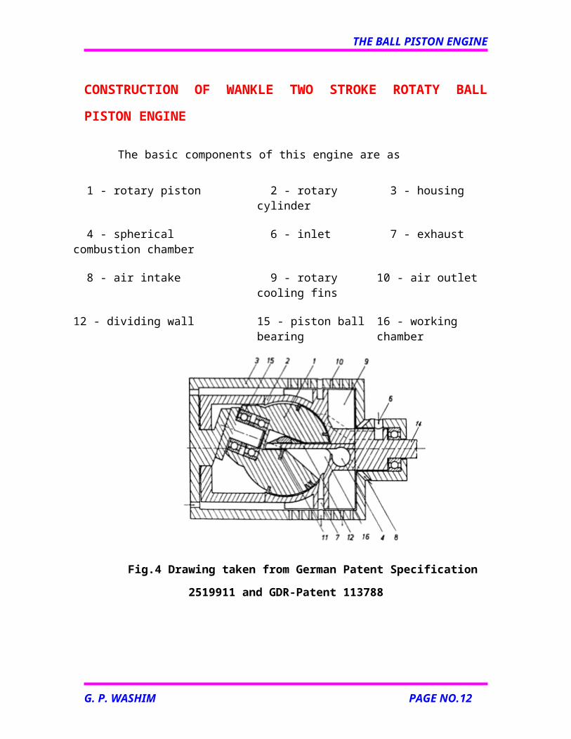
CONSTRUCTION OF WANKLE TWO STROKE ROTATY BALL
PISTON ENGINE
The basic components of this engine are as
1 - rotary piston 2 - rotary cylinder 3 - housing
4 - spherical combustion chamber 6 - inlet 7 - exhaust
8 - air intake 9 - rotary cooling fins 10 - air outlet
12 - dividing wall 15 - piston ball bearing 16 - working chamber
Fig.4 Drawing taken from German Patent Specification 2519911 and GDR-
Patent 113788
The principle components of this engine are two rotors: (1), an inner
piston rotor turning within (2), an external cylinder rotor, with both set at
oblique axial angles to one another. The piston rotor is a sphere, from which
a section resembling the shape of an orange wedge has been removed and
which rotates around two ball bearings, (15). The cylinder rotor is a hollow
G. P. WASHIM PAGE NO.8
THE BALL PISTON ENGINE
sphere of proportionate size enclosing the piston rotor. Both rotors turn in
concert at the same speed. Only their rotational axes are at an angle to one
another. For the spherical piston to be able to swivel inside the hollow
sphere/cylinder, both rotational axes must intersect exactly in the center of
the sphere. (This must be duly observed when constructing such an engine,
as otherwise reactive forces would be generated between the piston and the
cylinder.) If no errors have been made, the piston and cylinder turn freely
within one another without contact and without exerting unnecessary forces
on one another (apart from utilizable torque). The cylinder rotor is seated at
both ends in a stationary housing, (3) and possesses a shaft, (14). The
cylinder rotor separates lengthwise into two halves, allowing it to be placed
over the piston. Between these two halves, a dividing wall, (12) is also
screwed in, turning the sphere into two hemispheres. The piston rotor has a
corresponding cutout in the shape of an orange wedge, so that it can
accommodate this wall. In between, two symmetrical working chambers,
(16) are formed. (The whole unit resembles a joint for coupling two non-
aligned shafts. The dividing wall connects the two rotors in a torque-proof
fashion.)
G. P. WASHIM PAGE NO.9
THE BALL PISTON ENGINE
WORKING OF WANKLE ENGINE
A spherical piston rotates in combination with a spherical housing,
whereby the rotational axes alone incline towards each other slightly, not
unlike a cardan joint. In the process, “strokes” are created within the
rotational system, which are employed to produce periodic volumetric
change in working chambers. Two such symmetrical working chambers
arise in diametrically opposing sides of the spherical piston, in sections cut
out of the sphere like wedges removed from an orange, one on each side of a
smooth dividing wall that extends into these areas and which is firmly
anchored to the casing (external cylinder) that also rotates as part of the
system.
In order to understand what goes on inside this device, we will have to
take a look at the rotating system. Try to imagine yourself rotating along
with the cylinder rotor. You will observe a swiveling or tumbling motion of
the sphere-shaped piston in the sphere-shaped cylinder. The piston moves
back and forth at periodic intervals right up to the dividing wall, while
simultaneously swiveling lengthwise to it. It carries out a tumbling motion
that can be differentiated into two pivotal motions occurring vertically on
top of one another. One of these creates the desired stroke motion in the
rotating system, the other enables asymmetrical timing. This engine has the
kinematics of a single-rotational engine with the centers of gravity of both
rotating parts are at rest. In the coordinate system at rest there are, in the case
of this engine, no to and fro motions. The stroke motions exist only in the
co-rotating, body-fixed coordinate system and generate no oscillating inertial
forces. Consequently, this engine produces no vibrations resulting from
oscillating inertial forces. (Consideration of the sealing components is for
G. P. WASHIM PAGE NO.10
THE BALL PISTON ENGINE
the time being left aside as this would go beyond the scope here of general
descriptive purposes.)
Two rotors turn, one nested in the other. Contact between the two
occurs via the sealing components. The sliding speeds arising through the
motion of both parts tumbling in opposing directions in the co-rotating
system are in fact low. Accordingly, high revolutions per minute are possible
(more than 20,000 rpm). Centrifugal and other inertial forces are however
present and may affect particular sealing components at very high speeds.
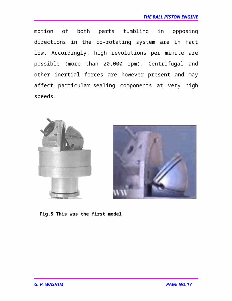
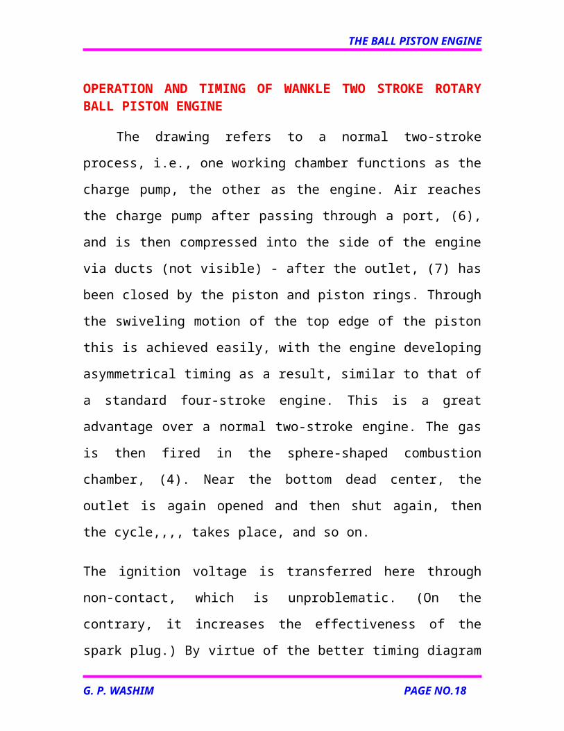
Fig.5 This was the first model
G. P. WASHIM PAGE NO.11
THE BALL PISTON ENGINE
OPERATION AND TIMING OF WANKLE TWO STROKE ROTARY BALL PISTON ENGINE
The drawing refers to a normal two-stroke process, i.e., one working
chamber functions as the charge pump, the other as the engine. Air reaches
the charge pump after passing through a port, (6), and is then compressed
into the side of the engine via ducts (not visible) - after the outlet, (7) has
been closed by the piston and piston rings. Through the swiveling motion of
the top edge of the piston this is achieved easily, with the engine developing
asymmetrical timing as a result, similar to that of a standard four-stroke
engine. This is a great advantage over a normal two-stroke engine. The gas
is then fired in the sphere-shaped combustion chamber, (4). Near the bottom
dead center, the outlet is again opened and then shut again, then the cycle,,,,
takes place, and so on.
The ignition voltage is transferred here through non-contact, which is
unproblematic. (On the contrary, it increases the effectiveness of the spark
plug.) By virtue of the better timing diagram and the significantly higher
volumetric efficiency – the “crankcase pump” here having almost no dead
volume – a single combustion stroke here produces more power than is the
case with a standard two-stroke engine, for which reason the engine output
per unit of displacement here is higher. Moreover, the number of
revolutions per minute can be increased even more, the bearings not being
subject to the otherwise high inertial forces, which in turn raises the engine
output per unit of displacement. It would thus be not only a prime mover for
lawnmowers and standard motorcycles and cars, but also a high-
performance engine for racing drivers.
G. P. WASHIM PAGE NO.12
THE BALL PISTON ENGINE
For standard cars, the engaging/disengaging of individual cylinders would
be more easily achievable, since they are anyway connected to each other
via cogs, gear wheels or similar means.
Other operations corresponding more to those of a turbine would also be
feasible.
The rotary piston apparatus could also serve as a compressor. It would be
less suited for work as a pump, however, since it would have the same high
pulsation rates as a typical two-cylinder piston pump.
Fig. 6 Different positions of the piston(The wall etc are removed)
G. P. WASHIM PAGE NO.13
THE BALL PISTON ENGINE
LUBRICATIONS AND COOLING OF ENGINE
Lubrication
As is the case with a standard four-stroke engine, an oil bath is
situated behind the piston, which in turn is fitted with oil scraper rings. Here,
attention must merely be paid to ensuring that the oil gathers externally,
because of the rotation. In fact, if outlet ports are placed in this area for the
oil, an oil pump can be potentially dispensed with. Otherwise, oil that is
pumped into the center also carries heat from the interior to the exterior,
which in turn can be utilized for cooling purposes.
Cooling
Plain and simple forced air lends itself as a cooling system here. There
are cooling fins attached to the outside of the cylinder rotor that
simultaneously act as fan blades. Cooling air is sucked in at the rear and
through channels, (8) inside and blown out through holes, (10) in the
housing, (3). (An oil circulation system could also be brought in for cooling
purposes.) A water-cooling system would not be so easy to bring about, but
would also be feasible. The manner of cooling depends on whether the
intention is to use the engine to power a lawnmower or a racing car.
G. P. WASHIM PAGE NO.14
THE BALL PISTON ENGINE
ADVANTAGES OF ROTARY BALL PISTON ENGINE
The ball piston engine (multi energy domain engine) having small
number of moving parts, the design implement a modified version
of the tried and proven thermodynamic otto cycle when use as a
engine.
It will give the future engineers new found freedom in tailoring the
combustion process.
The stroke magnitude and rate can be different for different stroke
in cycle (i.e. intake, compression, power and exhaust) so that it
provides the possibility of converting more energy to the shaft
power by greater expansion during the power stroke.
It has ability (i.e. in multi energy domain engine) to complete any
even numbers of strokes per revolution in single rotation of rotor.
This effectively multiplies the power output proportionally if
stroke is maintain constant.
In this engine the frictional losses are low and independent of
operating speed in contrast to conventional piston engine.
DISADVANTAGES
Leakage through the ball piston/cylinder gap is a significant
factor for engine efficiency at low speed.
Flow is choked during combustion due to high pressure
differential and small clearance area.
G. P. WASHIM PAGE NO.15
THE BALL PISTON ENGINE
The friction and wear at the ball piston/cylinder wall sliding
interface.
APPLICATION OF ROTORY BALL PISTON ENGINE
It can be applied compressor.
The multi cylinder ball piston engine can be applied to pump,
motor.
It can be applied to engine.
The wankle advanced two stroke ball piston engine can be
applied to land mover, standard motor cycle and car and also
for racing car.
G. P. WASHIM PAGE NO.16
THE BALL PISTON ENGINE
CONCLUSION
From analysis the design assumptions show that the ball piston
engine has potential for achieving higher efficiency than piston
internal combustion engine. Having only small moving parts and
achieving higher efficiency.
A new approach to kinematics design has devised to eliminate
friction contribution from internal forces in the engine. On the other
hand, conventional carburetion/induction and exhaust system are
applicable to the new engine.
G. P. WASHIM PAGE NO.17
THE BALL PISTON ENGINE
REFERENCES
www.google.com
www.howstuffwork.com
www.wikepedia.com
www.ballpiston.com
G. P. WASHIM PAGE NO.18