The Bahen Centre for Information Technology - engr.psu.edu · PDF fileelectrical design is...
13
The Bahen Centre for Information Technology University of Toronto ~ Toronto, Ontario, Canada Senior Thesis 2003 Lighting/Electrical Option Rebecca Ho 62 Electrical Study Scope of Study The Bahen Centre for Information Technology at the University of Toronto is one of the top information technology centers among universities in Canada. It hosts multiple computer labs featuring large numbers of workstations for students, faculty, and research use. The large electrical capacity of the building requires an extremely powerful and complex distribution system in order to satisfy the building’s electrical needs. For the electrical study portion of the thesis, only the existing electrical system will be analyzed and no redesigning will be performed. This is due to the fact that the Bahen Centre has an existing electrical system that is extremely advance and complicated. It would be too difficult to redesign the entire system without much of the crucial information which is unavailable for the purpose of this thesis. Therefore, a coordination study and analysis of the existing electrical system will be performed, with emphasis and detail studies on the more significant and special parts of the system. Overall Existing System Analysis One of the reasons why the electrical distribution system for the Bahen Centre project is quite intricate is because the electrical design is integrated in conjunction with the redesigning of the old electrical systems of the adjacent Fields Institute, Koffler Students Centre, and the Architecture Building (see Figure 8-1). In order to simplify the analysis, only the parts that are directly involved with the Bahen Centre will be studied. Figure 8.1 Site plan
-
Upload
truongkhanh -
Category
Documents
-
view
214 -
download
2
Transcript of The Bahen Centre for Information Technology - engr.psu.edu · PDF fileelectrical design is...

The Bahen Centre for Information Technology University of Toronto ~ Toronto, Ontario, Canada
Senior Thesis 2003 Lighting/Electrical Option Rebecca Ho
62
Electrical Study
Scope of Study The Bahen Centre for Information Technology at the University of Toronto is one of the top information technology centers among universities in Canada. It hosts multiple computer labs featuring large numbers of workstations for students, faculty, and research use. The large electrical capacity of the building requires an extremely powerful and complex distribution system in order to satisfy the building’s electrical needs. For the electrical study portion of the thesis, only the existing electrical system will be analyzed and no redesigning will be performed. This is due to the fact that the Bahen Centre has an existing electrical system that is extremely advance and complicated. It would be too difficult to redesign the entire system without much of the
crucial information which is unavailable for the purpose of this thesis. Therefore, a coordination study and analysis of the existing electrical system will be performed, with emphasis and detail studies on the more significant and special parts of the system. Overall Existing System Analysis One of the reasons why the electrical distribution system for the Bahen Centre project is quite intricate is because the electrical design is integrated in conjunction with the redesigning of the old electrical systems of the adjacent Fields Institute, Koffler Students Centre, and the Architecture Building (see Figure 8-1). In order to simplify the analysis, only the parts that are directly involved with the Bahen Centre will be studied.
Figure 8.1 Site plan
The Bahen Centre for Information Technology University of Toronto ~ Toronto, Ontario, Canada
Senior Thesis 2003 Lighting/Electrical Option Rebecca Ho
63
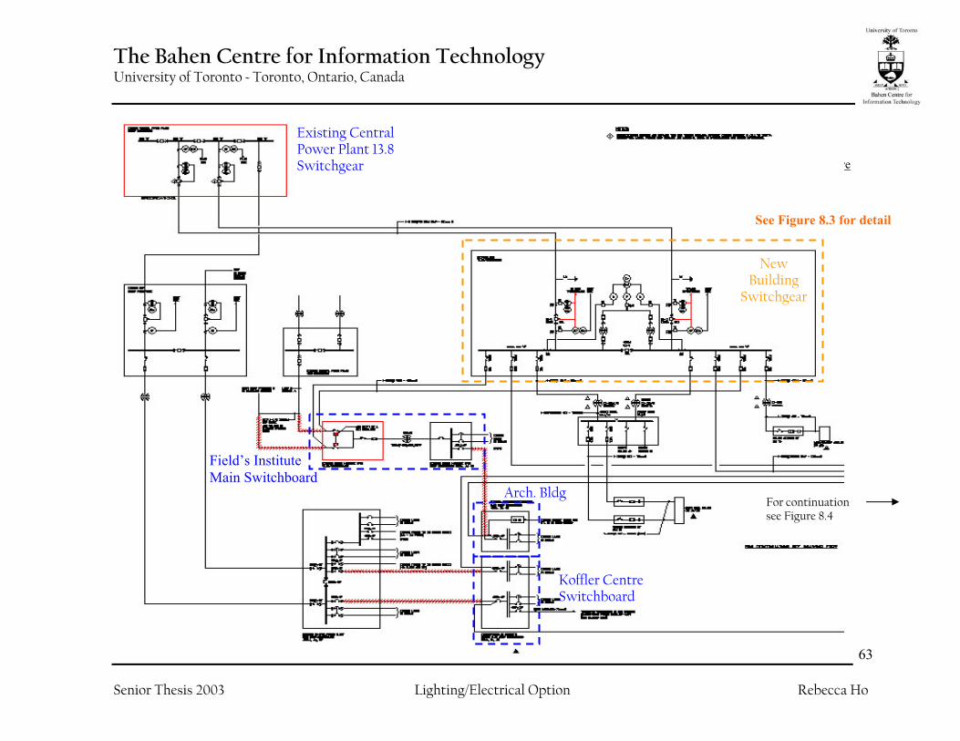
Figure 8.2 Single Line Diagram for the Bahen Centre
New Building
Switchgear
Existing Central Power Plant 13.8 Switchgear
Field’s Institute Main Switchboard
Arch. Bldg
Koffler Centre Switchboard
For continuation see Figure 8.4
See Figure 8.3 for detail

The Bahen Centre for Information Technology University of Toronto ~ Toronto, Ontario, Canada
Senior Thesis 2003 Lighting/Electrical Option Rebecca Ho
64
At the beginning side of the electrical system, power supply comes in through two high voltage primary distributions (13.8kV) from the existing central power plant located in another location within the university campus (Figure 8.2). These two high voltage paths of distribution are most likely to be isolated in location so that they can not be accidentally being dug up together.
The two high voltage lines becomes the two primary feeders of a what it is known as a secondary selective system, which in essence is two separate radial systems tied together with a tie-breaker in between, with many advantages which will be discussed later on. The system then splits into multiple feeds on the high voltage 1200A Bus “A”, with two branches to supply power to the Field’s
Figure 8.3

The Bahen Centre for Information Technology University of Toronto ~ Toronto, Ontario, Canada
Senior Thesis 2003 Lighting/Electrical Option Rebecca Ho
65
Institute. Two other branches supply power which is transformed down to 4160V by transformers TX-CHI1/1B and TX-CH2 for use of chillers and other mechanical equipment. Last but not least, two branches distribute power to the Bahen Centre, which is where the electrical analysis will focus on. As the power distribution system enters the Bahen Centre, the two main feeders are still carrying high voltages (13.8kV) into the building. These two lines form another secondary selective system, at which creates a redundancy of secondary selective systems (see Figure 8.4). The two feeds enters the main electrical room where the Delta-Y transformers TX-AB and TX-BB steps the power down to 347/600V for the building’s use. Power at this rating will be used for heavy equipment and most fluorescent lighting (a Canadian standard). Transformers located at each floor transforms the power again to a voltage rating of 120/208V for receptacles, lighting, and other power loads. On the distribution bus located after transformers TX-AB and TX-BB, a transient voltage surge suppression (TVSS) is used (see Figure 8.4), which will be discussed in later in the analysis. Three other feeds coming out of transformers TX-AB and TX-BB actually leaves the Bahen Centre to return and supply power to the adjacent Architecture Building and Koffler Student Services Centre. Branch feeders coming off of the low-voltage main bus then splits into various parts of the building for
various uses, such as elevator load and other service loads. The low voltage feeders then form the three risers of the building: the north, central, and south riser (See Figure 8.4 and 8.5). One portion of the risers that are worthy of mentioning is the use bus ducts in the Central and South Riser. The Central Riser uses an 800A, 3 phase, 4 wire bus duct; and the South Riser uses a 1200A, 3 phase, 4 wire bus duct. This will once again be discussed in detail later on in the analysis. As the electrical distribution gets closer to the user side, electric power is distributed through feeders placed underneath full access floors. The use of full access floors and its benefits will be discussed later on in the study.

The Bahen Centre for Information Technology University of Toronto ~ Toronto, Ontario, Canada
Senior Thesis 2003 Lighting/Electrical Option Rebecca Ho
66
Figure 8.4 ~ Continuation of single line diagram from Figure 8.2
Repeating of a secondary selective system
Power line returning to supply power to Architecture Building and Koffler Centre
Single-line diagram continued from Figure 8.2
North Riser
For continuation see Figure 8.5
Transient Voltage Surge Suppression (TVSS)

The Bahen Centre for Information Technology University of Toronto ~ Toronto, Ontario, Canada
Senior Thesis 2003 Lighting/Electrical Option Rebecca Ho
67Figure 8.5 Continuation of single line diagram from Figure 8.4
Central Riser
South Riser
800A 3Ph 4W Bus Duct
1200A 3Ph 4W Bus Duct
Single line diagram continued from Figure 8.4
The Bahen Centre for Information Technology University of Toronto ~ Toronto, Ontario, Canada
Senior Thesis 2003 Lighting/Electrical Option Rebecca Ho
68
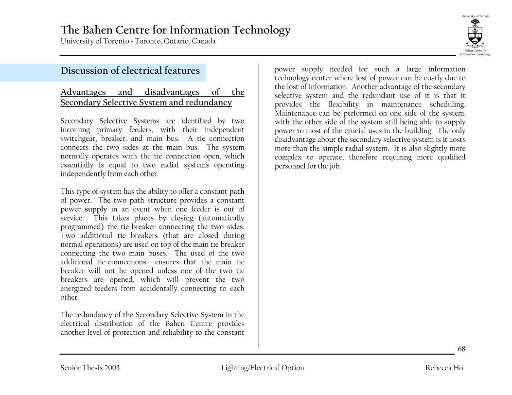
Discussion of electrical features Advantages and disadvantages of the Secondary Selective System and redundancy Secondary Selective Systems are identified by two incoming primary feeders, with their independent switchgear, breaker, and main bus. A tie connection connects the two sides at the main bus. The system normally operates with the tie connection open, which essentially is equal to two radial systems operating independently from each other. This type of system has the ability to offer a constant path of power. The two path structure provides a constant power supply in an event when one feeder is out of service. This takes places by closing (automatically programmed) the tie-breaker connecting the two sides. Two additional tie breakers (that are closed during normal operations) are used on top of the main tie breaker connecting the two main buses. The used of the two additional tie-connections ensures that the main tie breaker will not be opened unless one of the two tie breakers are opened, which will prevent the two energized feeders from accidentally connecting to each other. The redundancy of the Secondary Selective System in the electrical distribution of the Bahen Centre provides another level of protection and reliability to the constant
power supply needed for such a large information technology center where lost of power can be costly due to the lost of information. Another advantage of the secondary selective system and the redundant use of it is that it provides the flexibility in maintenance scheduling. Maintenance can be performed on one side of the system, with the other side of the system still being able to supply power to most of the crucial uses in the building. The only disadvantage about the secondary selective system is it costs more than the simple radial system. It is also slightly more complex to operate, therefore requiring more qualified personnel for the job.

The Bahen Centre for Information Technology University of Toronto ~ Toronto, Ontario, Canada
Senior Thesis 2003 Lighting/Electrical Option Rebecca Ho
69
Transient Voltage Surge Suppression Transient Voltage Surge Suppression (TVSS) is a term used for power conditioning method that protects the system from surges or spikes. The Transient Voltage Surge Suppressor limits the voltage’s surge to a certain level that the equipment connected to the circuit can handle. Impact of electrical surges and spikes can cause damages to the equipment such as computers that are connected to the electrical system. A device like this is vital in an information technology building because damages to computer equipments could be extremely costly.
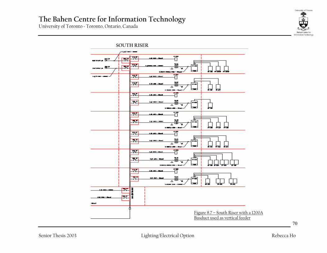
Busducts From figure 8.5, the uses of busducts are shown for the Central and the South risers of the Bahen Centre. The busducts used in the Bahen Centre are constructed of copper with a rigid metallic housing. They compose of three copper bars that run vertically through the building for vertical electrical distribution. They are primarily used on high rise and mid rise buildings due to the length of the vertical distance needed to reach. Although this type of distribution system can be very expensive, it is incredibly flexible and efficient. The advantage of using a busduct is that it has the capability to carry a large amount of power. The use of busducts allows the building operators to simply change out the plug in the breaker rather than running new conductors if the loads increase. Also, heavy-duty busducts, like the ones used in the Bahen Centre (which is 1200A), are suitable in applications with vertical feeders in high-rise buildings which require high power capacity with taps feeding each individual floor.
Figure 8.6 – A typical Transient Voltage Surge Suppressor that is used
at the incoming end of an electrical distribution system.
The Bahen Centre for Information Technology University of Toronto ~ Toronto, Ontario, Canada
Senior Thesis 2003 Lighting/Electrical Option Rebecca Ho
70
SOUTH RISER
Figure 8.7 – South Riser with a 1200A Busduct used as vertical feeder
The Bahen Centre for Information Technology University of Toronto ~ Toronto, Ontario, Canada
Senior Thesis 2003 Lighting/Electrical Option Rebecca Ho
71
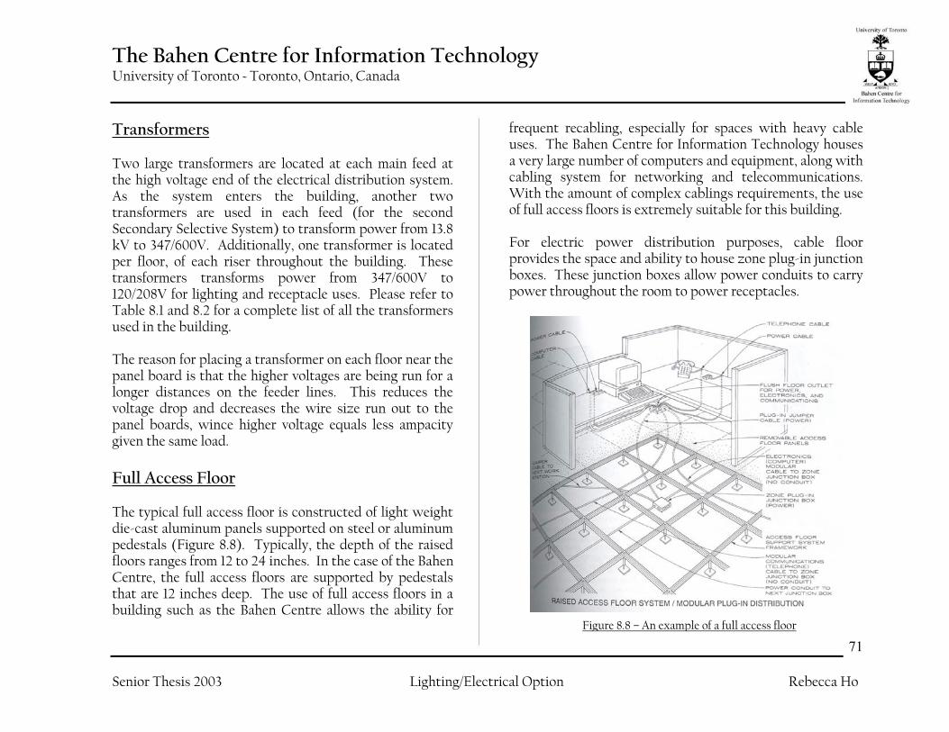
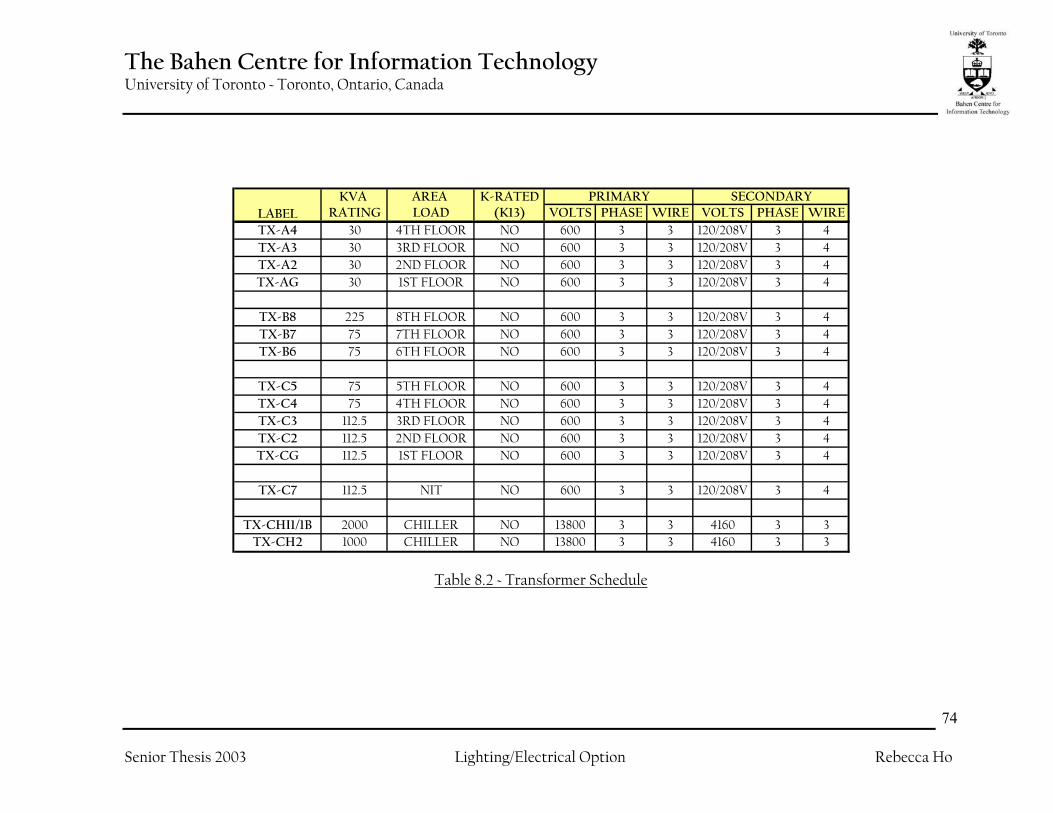
Transformers Two large transformers are located at each main feed at the high voltage end of the electrical distribution system. As the system enters the building, another two transformers are used in each feed (for the second Secondary Selective System) to transform power from 13.8 kV to 347/600V. Additionally, one transformer is located per floor, of each riser throughout the building. These transformers transforms power from 347/600V to 120/208V for lighting and receptacle uses. Please refer to Table 8.1 and 8.2 for a complete list of all the transformers used in the building. The reason for placing a transformer on each floor near the panel board is that the higher voltages are being run for a longer distances on the feeder lines. This reduces the voltage drop and decreases the wire size run out to the panel boards, wince higher voltage equals less ampacity given the same load. Full Access Floor The typical full access floor is constructed of light weight die-cast aluminum panels supported on steel or aluminum pedestals (Figure 8.8). Typically, the depth of the raised floors ranges from 12 to 24 inches. In the case of the Bahen Centre, the full access floors are supported by pedestals that are 12 inches deep. The use of full access floors in a building such as the Bahen Centre allows the ability for
frequent recabling, especially for spaces with heavy cable uses. The Bahen Centre for Information Technology houses a very large number of computers and equipment, along with cabling system for networking and telecommunications. With the amount of complex cablings requirements, the use of full access floors is extremely suitable for this building. For electric power distribution purposes, cable floor provides the space and ability to house zone plug-in junction boxes. These junction boxes allow power conduits to carry power throughout the room to power receptacles.
Figure 8.8 – An example of a full access floor

The Bahen Centre for Information Technology University of Toronto ~ Toronto, Ontario, Canada
Senior Thesis 2003 Lighting/Electrical Option Rebecca Ho
72
Conclusion on the design of the system Overall, the electrical system at the Bahen Centre is designed to provide a large amount of energy for the informational systems due to the large size of the building and the large amount of computer equipment used throughout the building. The design also has a high level of reliability and flexibility, while providing multiple levels of protection for equipments connected to the system. Even though that some of the equipments used maybe be very costly, it is more important to protect the equipments and the important information at which those computerized equipment carries.

The Bahen Centre for Information Technology University of Toronto ~ Toronto, Ontario, Canada
Senior Thesis 2003 Lighting/Electrical Option Rebecca Ho
73
KVA AREA K-RATEDRATING LOAD (K13) VOLTS PHASE WIRE VOLTS PHASE WIRE
TX-AP2 30 PARKING NO 600V 3 3 120/208V 3 4TXE-AP2 13 PARKING NO 600V 3 3 120/208V 3 4
TXE-AP1 15 LOADING NO 600V 3 3 120/208V 3 4
TX-AB 3500/4500 MAIN NO 13.8kV 3 3 347/600 3 4TX-BB 3500/4500 MAIN NO 13.8kV 3 3 347/600 3 4TX-CB 112.5 BASEMENT NO 600 3 3 120/208V 3 4TX-AP1 30 LOADING NO 600 3 3 120/208V 3 4TXE-AB 25 BASEMENT NO 600 3 3 120/208V 3 4
TXE-APH 15kVA PENTHOUSE NO 600 3 3 120/208V 3 4
TX-A8 112.5 8TH FLOOR NO 600 3 3 120/208V 3 4TX-A7 75 7TH FLOOR NO 600 3 3 120/208V 3 4TX-A6 75 6TH FLOOR NO 600 3 3 120/208V 3 4
TX-B5 150 5TH FLOOR NO 600 3 3 120/208V 3 4TX-B4 150 4TH FLOOR NO 600 3 3 120/208V 3 4TX-B3 150 3RD FLOOR NO 600 3 3 120/208V 3 4TX-B2 112.5 2ND FLOOR NO 600 3 3 120/208V 3 4TX-BG 75 1ST FLOOR NO 600 3 3 120/208V 3 4
LABELPRIMARY SECONDARY
Table 8.1 – Transformer Schedule
The Bahen Centre for Information Technology University of Toronto ~ Toronto, Ontario, Canada
Senior Thesis 2003 Lighting/Electrical Option Rebecca Ho
74
KVA AREA K-RATEDRATING LOAD (K13) VOLTS PHASE WIRE VOLTS PHASE WIRE
TX-A4 30 4TH FLOOR NO 600 3 3 120/208V 3 4TX-A3 30 3RD FLOOR NO 600 3 3 120/208V 3 4TX-A2 30 2ND FLOOR NO 600 3 3 120/208V 3 4TX-AG 30 1ST FLOOR NO 600 3 3 120/208V 3 4
TX-B8 225 8TH FLOOR NO 600 3 3 120/208V 3 4TX-B7 75 7TH FLOOR NO 600 3 3 120/208V 3 4TX-B6 75 6TH FLOOR NO 600 3 3 120/208V 3 4
TX-C5 75 5TH FLOOR NO 600 3 3 120/208V 3 4TX-C4 75 4TH FLOOR NO 600 3 3 120/208V 3 4TX-C3 112.5 3RD FLOOR NO 600 3 3 120/208V 3 4TX-C2 112.5 2ND FLOOR NO 600 3 3 120/208V 3 4TX-CG 112.5 1ST FLOOR NO 600 3 3 120/208V 3 4
TX-C7 112.5 NIT NO 600 3 3 120/208V 3 4
TX-CHI1/1B 2000 CHILLER NO 13800 3 3 4160 3 3TX-CH2 1000 CHILLER NO 13800 3 3 4160 3 3
LABELPRIMARY SECONDARY
Table 8.2 ~ Transformer Schedule