
The B61-based “Robust Nuclear Earth Penetrator:” Clever … · · 2008-02-04In an atmospheric...
34
arXiv:physics/0510052v1 [physics.soc-ph] 6 Oct 2005 The B61-based “Robust Nuclear Earth Penetrator:” Clever retrofit or headway towards fourth-generation nuclear weapons? Andre Gsponer Independent Scientific Research Institute Box 30, CH-1211 Geneva-12, Switzerland e-mail: [email protected] Version ISRI-03-08.14 February 4, 2008 Abstract It is scientifically and technically possible to build an earth penetrating device that could bury a B61-7 warhead 30 meters into concrete, or 150 meters into earth, before detonating it. The device (based on knowledge and technology that is available since 50 years) would however by large and cumbersome. Better penetrator materials, components able to withstand larger stresses, higher impact velocities, and/or high-explosive driven pene- tration aids, can only marginally improve the device. It is conclude that the robust nuclear earth penetrator (RNEP) program may be as much motivated by the development of new technology directly applicable to next generation nuclear weapons, and by the political necessity to periodically reasses the role and utility of nuclear weapons, then by the perceived military need of a weapon able to destroy deeply buried targets. 1 Introduction Nuclear weapons are the most destructive instruments of war available to the mil- itary. Their destructiveness is due to a number of effects — mechanical, thermal, and radiological — but by far the most important military effect of present-day nuclear weapons is due to the enormous shock-waves generated in the surrounding materials by the energy released from nuclear fission and thermonuclear fusion within the warhead. 1
Transcript of The B61-based “Robust Nuclear Earth Penetrator:” Clever … · · 2008-02-04In an atmospheric...

arX
iv:p
hysi
cs/0
5100
52v1
[ph
ysic
s.so
c-ph
] 6
Oct
200
5
The B61-based“Robust Nuclear Earth Penetrator:”
Clever retrofit or headway towardsfourth-generation nuclear weapons?
Andre GsponerIndependent Scientific Research InstituteBox 30, CH-1211 Geneva-12, Switzerland
e-mail: [email protected]
Version ISRI-03-08.14 February 4, 2008
Abstract
It is scientifically and technically possible to build an earth penetratingdevice that could bury a B61-7 warhead 30 meters into concrete, or 150meters into earth, before detonating it. The device (based on knowledgeand technology that is available since 50 years) would however by largeand cumbersome. Better penetrator materials, components able to withstandlarger stresses, higher impact velocities, and/or high-explosive driven pene-tration aids, can only marginally improve the device. It is conclude that therobust nuclear earth penetrator (RNEP) program may be as much motivatedby the development of new technology directly applicable tonext generationnuclear weapons, and by the political necessity to periodically reasses therole and utility of nuclear weapons, then by the perceived military need of aweapon able to destroy deeply buried targets.
1 Introduction
Nuclear weapons are the most destructive instruments of waravailable to the mil-itary. Their destructiveness is due to a number of effects — mechanical, thermal,and radiological — but by far the most important military effect of present-daynuclear weapons is due to the enormous shock-waves generated in the surroundingmaterials by the energy released from nuclear fission and thermonuclear fusionwithin the warhead.
1

In an atmospheric explosion the shock-waves generated in air propagate overlarge distances, destroying every building and laying downevery tree within about3 km from the point of explosion of a 1Megaton1 thermonuclear weapon. It is thisair-blast shock-loading effect combined with the incendiary effect of high-yieldthermonuclear explosion which is at the origin of the strategy of war deterrenceby mutually assured destruction.
However, if instead of striking relatively weak structuressuch as buildings theair-blast strikes the ground, most of the energy in the shock-waves is reflectedso that very little energy is in fact transferred to the ground. This very poor“coupling” of the energy released by an atmospheric explosion is due to the factorof about 1,000 difference in densities between the air and the soil, so that because ofenergy and momentum conservation the maximum energy coupling to the groundis at most of 15% [1, p.195]. More precisely, in the case of low-altitude near-surface explosions (which maximize the energy transfer to the ground) the typicaltheoretical energy couplings are between 5 to 10% for chemical explosions, andabout 8% for nuclear explosions — provided the direct coupling of X-rays2 (about6%) is added to the mechanical coupling (about 2%) [3, p.874].
Consequently, if the objective of a weapon is to destroy underground targetsby means of shock-waves, the obvious idea is to detonated it under the surface ofthe ground. This enables a reduction by a factor of about 10–15 in the explosiveyield of the weapon. Indeed, even for a rather shallow burial(about 0.6 meter), themaximum energy coupled to the ground by a 0.5ktfission-explosion was computedto be already about 30% of the total yield, an estimate that was confirmed by anuclear test conducted at the Nevada Test Site [4, p.899]. Therefore, nearly 100%coupling is achieved when a warhead is detonated at a few meters below theground, so that the explosion of an earth penetrating warhead (EPW) with a yieldof about 0.5Mt can in principle have the same destructive power as a 5Mt aboveground detonation.
The military rationale for developing and producing the B61-11 (that is the11th modified version of the B61 gravity bomb whose development started in1961) was therefore to provide a replacement for the 9MegatonB53 that wasintended to be used for destroying buried command centers and other undergroundtargets. Moreover, since the precision and the flexibility of the delivery of the B61
1We use italics whentons, kt, or Mt refer ot tons of TNT equivalent.2In principle one has to include the energy of the neutrons escaping from the warhead. This
contribution to the coupling is negligible for first and second generation nuclear weapons. However,for pure-fusion third and fourth generation nuclear weapons, energy transfer by neutrons becomespredominant. For such weapons the coupling to the ground or atarget can therefore be very large,even if the weapons does not penetrate into them [2].
2

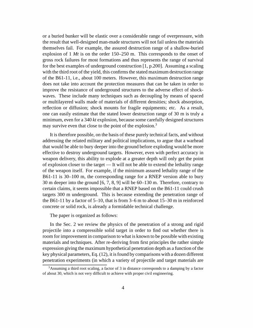
Figure 1: A number of components and a partially disassembled B61 bomb areshown in front of a fully assembled weapon (rear). The cylinder with a roundedhead on the left, located in the center subassembly of the B61, is the “physicspackage” containing the actual thermonuclear warhead.
were substantially greater than those of the B53, it was feltthat these advantageswould more than compensate for the lower yield of the B61, which is at most of340kt.
The B61-11 began entering service in 1997. It was therefore the first “new”nuclear weapon to enter into the arsenal of a declared nuclear power after theconclusion (in 1996) of the negotiations of the Comprehensive Test Ban Treaty,during which the United States stated that the B61-11 would be the last weaponto enter into its nuclear arsenal. So why is it that the UnitedStates administrationis now seeking a lifting of the 1993 ban on development of new nuclear weapons(the Spratt-Furse Law)? On 9 May 2003 a committee of the United States Senatepassed a bill to that effect, calling for the development of a“bunker buster” bombto be called the robust nuclear earth penetrator (RNEP).
Part of the reasons are of a military-technical nature: Eventhough the B61-11 can bury itself 3–6 meters underground before detonation, it cannot destroytargets at depths or distances much larger than 30–100 meters below or away fromthe point of explosion. This is because shock-waves propagating through a solidmedium are much less destructive that those propagating through air [5, Chap.6].For instance, ordinary buildings and even much stronger structures such as bridgesor above-ground military constructions are relatively brittle: The interaction of theblast-wave from an atmospheric explosion with them will be essentially inelastic,resulting in their complete failure at relatively large distances.
On the other hand, the interaction of an underground shock wave with a tunnel
3
or a buried bunker will be elastic over a considerable range of overpressure, withthe result that well-designed man-made structures will notfail unless the materialsthemselves fail. For example, the assured destruction range of a shallow-buriedexplosion of 1Mt is on the order 150–250 m. This corresponds to the onset ofgross rock failures for most formations and thus representsthe range of survivalfor the best examples of underground construction [1, p.200]. Assuming a scalingwith the third root of the yield, this confirms the stated maximum destruction rangeof the B61-11, i.e., about 100 meters. However, this maximumdestruction rangedoes not take into account the protection measures that can be taken in order toimprove the resistance of underground structures to the adverse effect of shock-waves. These include many techniques such as decoupling by means of spacedor multilayered walls made of materials of different densities; shock absorption,reflection or diffusion; shock mounts for fragile equipments; etc. As a result,one can easily estimate that the stated lower destruction range of 30 m is truly aminimum, even for a 340kt explosion, because some carefully designed structuresmay survive even that close to the point of the explosion.3
It is therefore possible, on the basis of these purely technical facts, and withoutaddressing the related military and political implications, to argue that a warheadthat would be able to bury deeper into the ground before exploding would be moreeffective to destroy underground targets. However, even with perfect accuracy inweapon delivery, this ability to explode at a greater depth will only get the pointof explosion closer to the target — It will not be able to extend the lethality rangeof the weapon itself. For example, if the minimum assured lethality range of theB61-11 is 30–100 m, the corresponding range for a RNEP version able to bury30 m deeper into the ground [6, 7, 8, 9] will be 60–130 m. Therefore, contrary tocertain claims, it seems impossible that a RNEP based on the B61-11 could crushtargets 300 m underground. This is because extending the penetration range ofthe B61-11 by a factor of 5–10, that is from 3–6 m to about 15–30m in reinforcedconcrete or solid rock, is already a formidable technical challenge.
The paper is organized as follows:
In the Sec. 2 we review the physics of the penetration of a strong and rigidprojectile into a compressible solid target in order to find out whether there isroom for improvement in comparison to what is known to be possible with existingmaterials and techniques. After re-deriving from first principles the rather simpleexpression giving the maximum hypothetical penetration depth as a function of thekey physical parameters, Eq. (12), it is found by comparisons with a dozen differentpenetration experiments (in which a variety of projectile and target materials are
3Assuming a third root scaling, a factor of 3 in distance corresponds to a damping by a factorof about 30, which is not very difficult to achieve with propercivil engineering.
4
used) that there is very little room for improvement: not more than 30 to 60%.
Starting form Sec. 3 we specialise to a concrete target, for which Eq. (17)gives a good estimate of the penetration depth as a function of the length, effectivedensity, and velocity of the penetrator. It is found that thestated penetrationcapability of the B61-11 is consistent with its published physical mensurationsand weights.
In Sec. 4 we give the physical and engineering reasons explaining the B61-7impact resistance (the B61-7 is the warhead of which the B61-11 is a ruggidizedearth-penetrating version), which enables it to withstandthe considerable decel-eration upon impact with the ground. We also derive simple formulas givingestimates for the maximum and mean decelerations during penetration.
In Sec. 5 we assess the scientific feasibility of a RNEP able tobury theB61-7 warhead 30 meters into concrete, or 100 to 150 meters into earth. Fourgeneral possibilities are analysed:(i) maximizing the weight and length of thepenetrator;(ii) maximizing the velocity of the penetrator;(iii) using conventionalpenetration aids such as a precursor shaped-charge jet; and(iv), assuming thatradically new types of compact nuclear explosives will become available in thenext few decades, speculations are made on hypothetical newdesigns which couldprovide a technically more attractive solution than the three previous possibilities.
In Sec. 6 we briefly recall the environmental and political limitations to the useof nuclear weapons, even when detonated underground. In particular, we stressthe political and nuclear proliferation problems posed by the “plutonium mines”created when an underground plutonium bomb explosion is contained.
In the last section, Sec. 7, we conclude that the technology for building aworking but cumbersome penetrator suitable to bury the B61-7 warhead 30 metersinto concrete is available, but that improving that penetrator and trying to reduceits size and/or weight by a factor of two will be very difficult, even if considerableadvances are made in the realms of materials science, micro-electromechanicalsystems’s engineering, and nanotechnology. Finally, considering these difficulties,as well as the military and political limitations to the battle-field use of existingtypes of nuclear weapons, we wonder whether apart from keeping the nuclearweapons debate alive, an important reason for considering anew generation ofnuclear earth penetrating weapons would not be to develop their associateed non-nuclear technologies, which overlap with those required for radically new types ofweapons, both conventional and nuclear.
5
2 Fundamental physical limits to kinetic penetration
A recurring suggestion in the non-technical literature is that by some new “trick”the penetration depth of a kinetic penetrator could be substantially increased(perhaps by a factor of ten or more) over what is presently possible with availablematerials and technologies, e.g., [9]. In order to show thatthis is not possible, wewill study a simple model in which everything is idealized except for the most basicprocesses which enable a high-velocity object to penetrateinto a material such assteel, concrete, or earth. Moreover, the model will be such that all approximationstend to overestimate the penetration depth, what is for instance the case for aone-dimensional model in comparison to a two- or three-dimensional one.
For this model we follow the general idea suggested in Ref. [10], namely thatwhen a high-velocity projectile penetrates into a materialit creates a shock wavewhich compresses and heats the material ahead of it: The maximum penetrationdepth is then obtained when the material immediately ahead of the projectile (i.e.,sufficiently heated to evaporate) is instantaneously removed by some ideal process,so that the penetrator can continue its course until its kinetic energy is exhausted,or some fundamental limit is reached. In other words, the basic idea is that thekinetic energy of the penetrator is entirely used to melt thematerial ahead of it,and that all other processes which remove that material are supposed to have noenergy cost. Similarly, it is supposed that the frictional forces on all sides of thepenetrator are negligible, and that all flows of materials inthe regions adjacent tothe surface of the penetrator are completely free. However,whereas the velocityis supposed to be high, it is not supposed to be so high that oneis in the high-velocity hydrodynamic-limit where all materials (including the penetrator whichin the present model is suposed to be perfectly strong and rigid) behave as idealincompressible-liquids, and all the kinetic energy is usedto move them aside fromthe path of the penetrator.
Let us therefore take a penetrator of lengthL, frontal areaS, densityρp,and very high compressive strengthYp; and a semi-infinite target of densityρt
and compressive strengthYt.4 To begin with we suppose that this penetrator isincompressible and sufficiently strong to remains intact during penetration intoa target.5 According to our model, at any given time during penetration, the
4To be precise, what matters most in the present problem is notthe “bulk compression modulus”K, but the “unconstrained (or unconfined) compressive strength.” For metallic projectiles andcohesive targets it has a magnitude comparable to the yield strengthYs, which is typically inthe range of 10 Mpa to 2 GPa. For cohesionless or granular targets such as soil or sand, theunconstrained compressive strength in on the order of 0.1 to10 MPa.
5That restriction will be removed at the end of this sections,when the maximum impact velocityconsistent with our model will be evaluated.
6
velocity of the projectilevp(t) is such that the compressive strength of the targetis exceeded, so that ahead of it the target material is compressed by a shock-waveto a densityρs > ρt. As we are considering large penetrations, we can assume thestrong shock limit, in which case
ρs = ρt
1 + γ
1 − γ, (1)
whereγ > 1 is the polytrope exponent.
The crucial step in the reasoning is now to apply energy-momentum con-servation to the shocked target material ahead of the penetrator, which implies
d(ρsSxvs) = ρsS(x dvs + vs dx) = 0, (2)
wherex is the distance measured (for convenience) from the back of the penetratorand vs(x, t) the velocity of the shocked material at any given time. With theboundary conditionvs(L, t) = vp(t), this equation is trivially integrated, i.e.,
vs(x, t) = vp
L
x, (3)
One can therefore calculate the energy distribution in the shocked material
Es(x, t) =
∫ x
l
1
2Sρsv
2
s = Ep
ρs
ρp
(1 −L
x), (4)
whereEp(t) = 1
2Sρpv
2
p(t) is the kinetic energy of the penetrator at timet. Byderivating this equation and dividing byS, or by directly using (3), one can alsocalculate the energy density, i.e.,
d Es
dV(x, t) =
1
2ρsv
2
s =1
2ρsv
2
p
L2
x2. (5)
The last equation can now be used to write down thecriterion for penetration,which is simply the condition that the energy density in front of the penetrator hasto be higher than that corresponding to the compressive strength of the target, i.e.,
d Es
dV(x, t) =
1
2ρsv
2
p
L2
x2≥ Yt. (6)
In particular, theminimum velocity6 of the projectile for penetration to proceeduntil it has come to a rest is given whenx = L, i.e.,
vp,min =
√
2Yt
ρs
. (7)
6This velocity is not the same as the usual estimate for penetration to occur, which is derivedfrom the ratio of the projectile ram pressure1
2ρpv
2
pto the target compressive strength, i.e., Eq. (7)
with ρs replaced byρp.
7
Equation (6) can also be used to calculate the thickness∆z = x − L of theshocked region such that its energy density exceedsYt, i.e.,
∆z + L = L
√
ρs
2Yt
. (8)
In the present model, the energy∆E = Es(∆z + L, t) given by Eq. (4) corre-sponds to the energy used to “evaporate” the material in the region of thickness∆z ahead of the penetrator. Therefore, since that material is supposed to be in-stantaneously removed out of its way, the penetrator’s linear energy loss is givenin first approximation by
dEp
dz≈ −
∆E
∆z= −
Ep
L
ρs
ρp
√
2Yt
ρs
1
vp
, (9)
or, expressingvp in terms ofEp and rearranging, by
dEp
2√
Ep
= −
√
S
L
ρt
ρp
Yt dz, (10)
where, because the removed material is in gaseous form, we have approximateits adiabatic exponent by that of a monoatomic gas, i.e.,γ = 5/3, so that Eq. (1)givesρs = 4ρt.
Equation (10) is easily integrated by quadrature, giving the penetration depthD = z in function of the initial and final penetrator energies
D =
√
L
S
ρp
ρt
1
Yt
(
√
Ep(0) −√
Ep(1))
, (11)
or in function of the initial and final penetrator velocities
D = Lρp
ρt
√
ρt
2Yt
(
vp(0) − vp(1))
, (12)
where the final velocityvp(1) can been replaced by the velocity given by Eq. (7),i.e., assuming againγ = 5/3,
vp(1) =
√
Yt
2ρt
. (13)
8

The main result of our model, equation (12),7 is remarkable because it explainsessentially all the important qualitative features observed in penetration experi-ments: direct proportionality to the length, density, and velocity of the penetrator;inverse proportionality to the square root of the density and compressive strengthof the target; and existence of a minimum velocity.
On the other hand, when making quantitative comparisons with the data, itturns out — as expected form the discussion in the introduction to this section— that Eq. (12) tends to overestimate the penetration depth.This can be seen,for example, if one looks at the penetration depth versus striking velocity ofsteel projectiles into concrete data of Ref. [11] shown in Fig. 2 of Ref. [12]. Inthat case Eq. (12) overestimatesD by a factor of≈ 2.8. But, if one makes thecomparison with the data of Ref. [13] shown in Fig. 7 of Ref. [14], the discrepancyis only a factor of≈ 1.5; and a factor≈ 2.1 when compared with the data ofRef. [15] (see, Table 1). Consequently, although the details of the experimentalconditions and the exact properties of the materials used are not well known, the“hypothetical maximum room for improvement” suggested by these comparisonsis small: at most between a factor 1.5 and 3. To better understand what this meansin practice, further comparisons with other experiments using other target andprojectile materials are made in Table 1.
Let us define the hypothetical room for improvement by the ratio R betweenthe hypothetical maximum penetration given by Eq. (12) and the correspondingmeasurement for a given penetrator lengthL at a normalized penetrator velocityof vp(0) = 1 km/s, i.e.,R = (D/L)hyp/(D/L)exp at that velocity. For the sakeof comparison, and in order to exhibit some possible trends,the data in Table 1is listed in approximately increasing order ofR, except for the last experiment inwhich the target is a low density foam. As can be seen, the smallest room forimprovement is with the steel (i.e.,ρp = 7.9 Mg/m3) projectiles into concrete data,possibly because everything feasible has already been donewith them in order tofacilitate their penetration, e.g., maximal hardness, ogival nose shape, and largelength over diameter ratio (“long rod” penetrator).
The second set of data, from Ref. [16], is for spherical ballsof tungsten carbide(i.e., ρp = 15 Mg/m3) into various typical armor materials: rolled homogeneousarmor (RHA) steel, titanium, polycarbonate (G.E. Lexan), and 1100-F aluminum.As can be seenR is comprised between 2.8 and 4.5, with a slight trend towards
7While dimensional analysis directly leads to its general form, and many papers use it in a formor another, I have not found a published derivation from firstprinciples of this equation.
9
Comparison of ideal maximum penetration formula, Eq.(12), to the data
ρt Yt D/L d/l vf D/L R[kg/m3 [MPa] (exp) [s/km] [km/s] (12)
Concrete [13] 2310 34.7 12 20 0.09 18 1.5
Concrete [15] 2300 62.8 6.1 15 0.11 13 2.1
Concrete [11] 2500 50 5 16 0.10 14 2.8
Steel [16] 7900 1000 1 3.8 0.25 2.8 2.8
Titanium [16] 4500 800 1.2 5.5 0.30 3.9 3.2
Lexan [16] 1210 60 10 40 0.16 34 3.4
Aluminum [16] 2700 100 4 21 0.14 18 4.5
Grout [15] 2000 21.6 7.6 27 0.07 25 3.3
Grout [15] 2000 13.5 8.1 34 0.06 32 4.0
Lead [10] 11300 17 2.5 3 0.03 13 5.2
Foam [10] 110 20 120 120 0.30 85 0.7
Table 1: RatioR = (D/L)hyp/(D/L)exp normalized to an impact velocity ofvp = 1 km/s, where(D/L)hyp = d/l(vp − vf) is calculated with Eq. (12), and(D/L)exp is measured for the materials listed in column 1 to 4. The symbol d/l isthe slope coefficient andvf the final penetrator velocity given by Eq. (13).
10

an increase when going from hard to softer materials. Clearly, by modifying thepenetrator shape and thus minimizing its drag coefficient,R could be significantlyreduced. This effect is well known and accounts for a factor of about 2 whengoing from a flat to a conical shape (see, e.g., [12, p.6]).8 A further reduction ofR,possibly by a factor of 1.5, will arise from taking into account the energy neededto moved the target material out of the way.
The third set of data are two experiments with ogive-nose steel projectileimpacting grout with two different compressive strengths [15]. The trend for anincrease ofR when going from harder to softer materials is observed again.
The last set of data, from Fig. 116 of Ref. [10], is for spherical balls ofsteel into a soft and heavy material (lead), or a low density foam (assumed tobe polyethylene). In the case of lead the hypothetical room for improvement is5.2, suggesting that for this material the idealizations leading to Eq. (12) are notadequate: in particular, the compressive strength is so small that little energy isneeded to crush it, while significant amounts are actually needed to sweep it aside.Finally, in the case of the low-density foam, the material can no more be consideredas a “solid,” even at the relatively high impact velocities considered here: Eq. (12)fails and another model should be developed.9
Consequently, by taking into consideration the most obvious detrimental effectsthat were neglected in the derivation of Eq. (12), the data inTable 1 showsthat instead of a room of improvement of about 3 to 4 as suggested by a naiveinterpretation, the actual margin cannot be more than a factor of about 1.5 to 2,or possibly even less considering the complexity and numberof small effects thatshould be considered at the detailed level.
In particular, this implies that processes such cavitation, which can have asignificant impact in aerodynamics and low-velocity hydrodynamics [18], will notbe able to play any significant role in improving penetrationinto a solid target [9],except possibly when driving into soil or mud. Similarly, using a composite ornano-engineered material instead of steel [19], or a heavy-material like uranium(which by adiabatic shearing enables to improve long-rod penetration into a metal10
by about 10% at high-velocities [17, 20]) for the penetrator, will only have marginalimpacts on penetration depth apart from those due to their density.
8This effect remains significative in the 1 to 2 km/s velocity range where going from a flat to asharp nose accounts for a factor 1.4 in penetration depth [17].
9Although R ≈ 0.7 is not a bad theoretical estimate, the large value ofvmin, especially incomparison to that of lead, suggests that a different model is definitely required. In effect,vmin isthe minimum velocity for shock-yielding to be the dominant penetration mechanism, while for asoft material penetration occurs at a much lower velocity.
10But not into concrete or rock.
11
Before summarizing, let us recall that the purpose of our model was not toprovide an exact fit to the data, but rather to give an estimatefor a hypotheticalmaximum penetration depth assuming that all the kinetic energy of a perfectlyhard projectile is used to “punch” a hole through the target,i.e., that none of thatenergy is used to remove the material evaporated at the head of the penetrator,and that none of that energy is lost as mechanical energy or stored as elasticenergy, but rather converted to heat in order to vaporize thematerial ahead of thepenetrator. This means that no conceivable physical process can possibly beat themaximum penetration given by Eq. (12). Moreover, if the projectile itself cannotbe considered as perfectly hard, Eq. (12) will provide and even larger upper limitto the actual maximum penetration depth. This happens when the velocity of theprojectilevp is so large that the ram pressure exceeds its compressive strengthYp, and that it begins to erode and loose rigidity. An estimate for thatmaximumvelocityis provided by going to the projectile rest frame, where the ram pressureis 1
2ρtv
2
p, giving the expression
vp,max ≈
√
2Yp
ρt
. (14)
Then, inserting Eq. (14) in (12), we can derive a simple formula for the maximumpossible penetration at maximum projectile velocity
Dmax ≈ Lρp
ρt
(
√
Yp
Yt
−1
2
)
, (15)
which like Eq. (12) will of course overestimate the actual maximum possiblepenetration depth.11
In conclusion, even if for some improbable reason the maximum penetrationdepths could be larger then given by Eqs. (12) or (15) — say by afactor of twoor three — the maximum hypothetically possible penetrationdepth would stillnot be larger than the experimentally measured and theoretically known values byone order of magnitude.12 Therefore, any conceivable improvement in projectiletechnology cannot increase penetration by a factor of be more than about 1.5 to 2.Finally, for the penetration depth into a solid to be maximum, the projectile velocityhas to be comprised between the two values approximately given by Eqs. (7) and
11For the steel into concrete data of Ref. [11] one finds that(D/L)max ≈ 5, while Eq. (15) givesabout 11, i.e., a factor of 2.4 more, as could be expected fromthe value ofR given in Table 1.
12The only debatable parameter in Eq. (12) is the polytrope exponentγ implicitly introducedthrough Eq. (1). If a reasonable value different from 5/3 is taken for this parameter, the depthsgiven by Eqs. (12) or (15) will be at most different by a factorof two. This has, however, noinfluence on what is physically possible in order to improve penetration.
12
(14). Belowvp,min penetration is not possible, and abovevp,max penetration willdecrease because of projectile erosion until it possibly reaches the hydrodynamiclimit given by the well known formula
Dhydro = L
√
ρp
ρt
, (16)
which always gives a smaller penetration depth than Eq. (12), even when modifiedto take compressibility effects into account, e.g., [21, 22].
3 The penetration capability of the B61-11
The present earth penetrating version of the B61, i.e., the B61-11, has a lengthL = 3.7 m, a maximum diameterd = 0.33 m. Its total weight isM ≈550 kg,about 200 kg more than the B61-7, the model of which the B61-11is a modifiedearth-penetrating version. Further characteristics of the B61-7 and 11 are listed inTable 2, and additional information can be found in references [23, 24, 25, 26, 27,28].
Assuming that the overall shape of the B61-11 can be approximated by anovoid, its volume will beV ≈ (π/6)d2L = 0.21 m3, which means that theeffective density of the B61-11 isρeff = M/V ≈ 2.6 Mg/m3 — about three timesless than if it was made out of solid steel.
Let us suppose that the target material consists of concrete, for which wetake the characteristics listed in the second line of Table 1. For the sake of theargument, let us also suppose that Eq. (12), which gives the hypothetical maximumpenetration depth, is overestimating the actual penetration depth by a factor of≈ 3,i.e., the average value ofR listed in the last column of Table 1. Taking this factorinto account, we therefore get the following expression
D ≈ 5Lρeff
ρFe(vp[km/s]− 0.1), (17)
which agrees well with the data and the two empirical formulas given in Ref. [12]whenρeff = ρFe.
In Eq. (18) the penetrator’s material enters by only one of its physical properties:the effective densityρeff. This is an elementary but important point which, by goingthrough the physical reasoning leading to Eq. (12), comes from the fact that for aperfectly hard and strong projectile the only thing that matters for penetration isits total kinetic energy.
13
Another trivial but important feature of Eq. (18) is that it contains theproductof ρeff by L, a quantity called “opacity,” and which appears in many physicalproblems. Consequently the penetration is the same if the density of a projectileis doubled at the same time as its length is halfed, provided the penetration ismeasured from the surface of the target to the tip of the penetrator when it comesto a rest. This implies that is not necessary to know how the mass is distributedwithin the penetrator. For example, in the case of the B61-11, one can supposethat its 550 kg are uniformly distributed over its 3.7 m of length, or else supposethat it is concentrated in the first half (which is actually not far from being thecase, as can be seen in Table 2) and assume that its length is only 1.85 m.
The notion that theeffective opacityρeffL is the decisive13 projectile-dependentparameter defining its penetration capability implies thatknowledge of the con-struction details of the B61-11, or any future RNEP, is not necessary. For example,looking at the numbers in Table 2, we see that out of the 203 kg mass differencebetween the B61-7 and B6-11, 133 kg are in the front. To account for this differ-ence several hypothesis can be made. For example, if we approximate the noseby a cone with base diameterd, and assume that its made out of steel with density7.9 Mg/m3, it would weight 146 kg. On the other hand, if we approximate the newpenetration aid subassembly by a cylinder of diameterd, and assume that its madeout of a tungsten or depleted uranium alloy of density 18 Mg/m3, it would weight153 k. After properly adjusting the numbers, either option would lead to the sameeffective opacity, and thus the same penetration. However,for many reasons suchas flight stability and terminal guidance, neither of these options will be optimum.
Let us now consider the penetration capability of the B61-11. If it is droppedfrom a height ofh = 12, 500 m, as in typical drop tests [12], its maximum groundimpact velocity neglecting air drag would be
vp(0) =√
2gh ≈ 500 m/s. (18)
Consequently, at a terminal velocity of 0.5 km/s, Eq. (17) gives a penetrationinto concrete of 2.4 m, i.e.,D/L ≈ 0.65,14 in agreement with the advertisedcapability of the B61-11. Indeed, if instead of concrete thetarget was the “frozenAlaska tundra” or the “Nevada test site alluvium,” which have densities similar toconcrete and a somewhat lower compressive strength, the penetration would havebeen 4–6 meters for the same drop height.
13As we have seen in the previous section, once obvious steps such as optimizing the penetrator’sshape have be taken, very little room is left for improvement.
14This implies that the warhead should be in the front-half of the bomb, which is actually thecase since it is located in the center subassembly, see Table2.
14
Comparison of B61-7 and B61-11 weights and lengths
B61-7 B61-11 B61-7 B61-11Subassembly Mass Mass Length Length
[kg] [kg] [m] [m]
Nose 0.65 0.65Center 1.15 1.15
Penetration aid 0.10Nose + center + penetrator 243 377 1.80 1.90
Preflight controller 23 23 0.30 0.30
Tail 80 150 1.50 1.50
Total 346 549 3.60 3.70
Table 2: The weights are from Ref. [28, Table 3.2], and the lengths are estimatedfrom Ref. [24, p.166] and [28]. The maximum diameter of both bombs is≈ 0.33 m.
How could this penetration capability be increased? Obviously, one couldincrease the impact velocity by fitting the bomb with a rocketengine, and possiblyreach the maximum set by the strength of the bomb casing, i.e., Eq. (15) whereone has to divided by 3 to be consistent with Eq. (17). For example, if thebomb’s casing is made out of steel so thatYp ≈ 1 GPa,15 that maximum would beD ≈ 4.2Lρeff/ρFe, i.e., approximately5 m in concrete — quite far away from thegoal of 30 m penetration in concrete or hard rock mentioned for the RNEP in thegeneral scientific literature [8, 9].
4 The robustness of the B61-11
Before discussing a number of possible designs which could lead to greater pene-tration depths, it is useful to make a few comments based on elementary physicalconsiderations, which explain how the B61-7 warhead contained in the B61-11can withstand the enormous deceleration of impact and penetration. This is par-ticularly important since any possible future RNEP will most probably also usethis warhead, because in the absence of nuclear tests an entirely new fission-fusionwarhead cannot easily be developed, and would not have the same deterrence valueas a fully tested warhead.
15In the case of maraging steel one could haveYp ≈ 2.6 GPa.
15
Figure 2: Main nuclear components of an early version of the B61 [29]: thefission primary (spherical and hemispherical parts), the fusion-fission secondary(cylindrical parts), and the two ends of the radiation case.The primary has alevitated pit: the small sphere at the bottom center with a hole for the deuterium-tritium boost gas supply.
In order to have a quantitative characterization of the robustness of the B61-7,it is necessary to find an estimate of the magnitude of deceleration during impact.A first approximation to this is obtained by assuming that after free-fall from aheighth a perfectly strong penetrator of massm and lengthL is decelerated bya constant accelerationamean, so that the equationmDamean = mhg gives theestimate
amean≈h
Dg, (19)
whereg the acceleration of Earth’s gravity. Forh = 12, 500 m andD = 2 m thisgives a mean decelerationamean≈ 6, 000 g.
Is it possible that a nuclear warhead can withstand such a large mean acceler-ation? The answer is certainly yes since earth penetrating warheads and nuclearartillery shells have been designed and deployed in the 1950s already. This givesan opportunity to make an estimate for the maximum acceleration during impact,and to compare that estimate with what is known about the robustness of nuclearartillery shells. Suppose therefore that the ram pressure of a projectile striking atarget (both assumed to be perfectly strong) isp = 1
2ρpv
2
p and that the pressure atimpact can be written asp = mamax/S whereS is the projectile’s cross-sectionalarea. In the case of an artillery shell elementary ballisticphysics shows that theprojectile’s velocity is related to the maximum range by therelationv2
p = grmax.
16

Thusamax ≈
rmax
2Lg, (20)
whereL is now the length of the shell assumed to be a cylinder. If we take forexample the W82 warhead, i.e., the “neutron bomb” artilleryshell,L = 0.87 mandrmax ≈ 30 km, giving a maximum accelerationamax ≈ 1, 7000 g at impact.In fact, by time symmetry, the argument leading to that estimate can be reversedand interpreted as the maximum acceleration during launching of the shell by anartillery gun, which in the case of the W82 is known to be 15,000 g [30],16 so thatour estimate is reasonable.
How can a nuclear warhead survive an acceleration or deceleration on the orderof 15,000g? Clearly, the warhead should contain a minimum of moving partsand all components must be mounted securely to resist shocks. Therefore all freespaces have to be filled by a strong light-weight material such as polyurethaneor beryllium, of such a density that it is compatible with thefunctioning of thewarhead. Moreover, since the crushing pressures are longitudinal, the warhead’sdesign should if possible be cylindrical rather than spherical.
For example, the early version of the B61 shown in Fig. 2 has a levitatedfissile pit that must be precisely positioned at the center ofthe reflector and high-explosive shells surrounding it. Because of the relativelyhigh densities of uraniumor plutonium, such a design cannot resist very large shocks,which is why mostversions of the B61 are “lay-down bombs,” i.e., bombs that are slowed-down by aparachute and ment to explode once they are at rest on the ground.
One the other hand, the W48 artillery shell developed between 1957 and1963 shown in Fig. 3 is based on a hybrid gun-assembly/implosion design witha diameter of less than 15 cm. This cylindrical design, code-named “Manticore”in Ref. [32], was first tested in 1955 and opened the way to the development ofcylindrical primaries for two-stage thermonuclear weapons. It is therefore mostprobable that cylindrical primaries are used in the warheads of the W82 and B61-7,and therefore the B61-11. A French experiment related to such primaries is shownin Fig. 4.
5 Scientific feasibility of a RNEP
The robust nuclear earth penetrator (RNEP) program is an engineering feasibilitystudy under way since May 2003 in the United States, with the objective to
16“The W82 warhead for the 155-mm nuclear projectile (...) must survive a 15,000g accelerationat launching” [30].
17
Figure 3: Schematic of a W48 nuclear artillery shell [31]. A critical mass isobtained by first gun-assembling two U-235 components and then imploding themradially. Because the overcriticality achievable is limited the yield is “very small,”probably 0.1kt [23].
Figure 4: Flash X-ray radiography of the implosion of a thin cylinder by confinedhigh-explosives [33]. The broken lines indicate the initial shape of the cylinder. Aconsiderable advantage of cylindrical primaries is that a sealed deuterium-tritiumboost gas reservoir can be inserted and removed axially for safety and maintenance.
18
determine if a more effective earth penetrating weapon could be designed usingmajor components of existing nuclear weapons. This is a quite ambitious objectivebecause the engineering aspects of the problem are very complex.
In this section we focus on a less difficult objective, i.e., to determine if itis scientifically possible to envisage a RNEP capable of penetrating 30 m ofconcrete [7, 8, 9].17 Specifically we will consider four possibilities, and discussthem in order of increasing sophistication, which in the medium to long term maycorrespond to increasing order of plausibility.
5.1 Maximization of effective opacity
According to Eq. (17), the most simple approach to increasing penetration is tomaximize the effective opacity because when dropped from a given height theterminal velocity does not depend on the penetrator’s mass or size (as recalled byEq. (18)). This approach was actually taken in 1991 at the endof the Gulf war todestroy a well-protected bunker north of Baghdad after repeated directed hits.
In that case an earth penetrating bomb, named GBU-28, was hastly createdusing a 3.9 m-long, 36 cm-diameter, surplus Army eight-inch-bore gun tube filledwith high-explosives [34, 35]. By taking densities of 7.9 and 1.9 g/cm3 for thesteel and the high-explosives, respectively, the weight ofthe GBU-28 comes outto be about 2,300 kg, and its effective density approximately 6,000 kg/m3. Fora length of 3.9 m and a terminal velocity of 0.5 km/s the penetration in concretegiven by Eq. (17) is 5.9 m, in good agreement with the improvedversion, GBU-28/BLU-113, which is claimed to “break through 7 meters of concrete or 30 metersof earth” [9].
Moreover, the same approach was already taken in the 1950s for designingearth-penetrating nuclear weapons [27]. For instance, “the uranium gun-type Mark8 bomb (nicknamed ‘Elsie’ for LC, or light case) was almost 3 meter long, 36 cmin diameter, 1,500 kg, and had a yield of approximately 25kt. (...) The Mark 11was an improved version of the Mark 8, slightly heavier, and according to theNational Atomic Museum, ‘able to penetrate up to 6.6 m of reinforced concrete,27 m of hard sand, 36 m of clay, or 13 cm of armor plate,’18 and fuzed to detonate90–120 seconds after penetration” [27]. In other words, thecharacteristics ofthis 1950-design are very similar to those of the GBU-28, except for the nuclearwarhead.
17This would correspond to about 100 to 150 m of earth.18There could be an error with the armor plate thickness, whichshould be more like 26 cm.
19

Using the same method one can easily propose a design for a weapon ableto break through 30 meters of concrete, i.e., five times more.First, one canreplace the steel tube by one made out of a strong tungsten or uranium alloy (withdensities of≈ 17g/cm3) and get this way an effective density possibly as largeas 15,000 kg/m3. Second, in order to get the desired factor of five increase ineffective opacity, one can double the length of the penetrator so thatL = 7.8 m,and the total weight becomes2, 300 × 5 = 11, 500 kg.
Will such a design work? Most probably yes, provided the 8-meter-long 10-ton-heavy penetrator can be delivered and properly guided to the target, whichseems possible since its aspect ratio of7.8/0.36 ≈ 22 is similar to that of amodern kinetic-energy antitank penetrator. But what aboutthe deceleration onimpact — will it differ from that of B61-11 for which Eq. (19) gave an averagevalue of 6,000 g assuming a penetrationD = 2 m? As a matter of fact, no: fora penetration of 30 m Eq. (20) actually gives a mean deceleration of only 400g.Indeed, the maximum impact pressure, which can be estimatedby Eq. (19), doesnot depend on the penetration depth or the penetrator’s weight, only on its lengthLso that the mean deceleration is smaller for a greater penetration depth. Moreover,by going to the penetrator’s rest-frame, one sees that the target is always impactingthe penetrator with the ram pressurep = 1/2ρtv
2
p, which does not depend on anyof the penetrator’s characteristics except velocity. Thus, a warhead that survivedpenetration after free-fall from a given height, will also work for a heavier andlonger penetrator able to penetrate deeper into the ground after falling from thesame height.
In summary, by simply increasing the effective opacity of the penetrator onecan — in principle — achieve any desired penetration, and theexisting B61-7 warhead can be used as the explosive charge with only minor modifications.However, the actual delivery, guidance, and successful penetration of the resultingvery-heavy and very-long penetrator will pose considerable engineering problems,which are out of the scope of the present paper.
5.2 Maximization of impact velocity
As shown by Eqs. (12) or (17), the second general possibilityto increase penetrationis to augment the impact velocity. This can be done for example with a rocket-engine fitted to the bomb, which has the advantage that the weapon could bereleased by a low-flying aircraft rather than dropped from a stratospheric bomber.
However, it is not possible to increase the impact velocity beyond the materiallimit set by the condition that the penetrator has to remain intact upon impact and
20

during penetration, a limit that is defined by the yield (or compressive) strengthof the penetrator casing. Moreover, as will be shown below, increased velocityalso means increased maximal impact deceleration, which results in severe con-straints on the nuclear warhead and its ancillary components. For these reasons, arealistic design will most probably be a compromise in whichthe impact velocityis increased at the same time as the effective opacity of the penetrator. However,in order to simplify the argument, we will assume in this subsection that the pri-mary free parameter is the impact velocity, and that everything is done to make itsincrease possible.
Let us rewrite Eq. (12) in the form
D ∝ ρpL( vp(0)√
2ρtYt
−1
2ρt
)
, (21)
where the ‘proportional to’ symbol has been introduced in order to stress that whatwe are interested in is the scaling of the penetration depth with the materials’sproperties, and where the maximum initial velocity consistent with the compressivestrength of the penetrator is approximately given by Eq. (14), i.e.,
vp,max(0) ≈
√
2Yp
ρt
. (22)
Let us consider again a concrete target, and suppose that we accept as a startingpoint a 4 m-long steel penetrator similar to the GBU-28. Since it is capable ofpenetrating 6 m of concrete at an impact velocity of 0.5 km/s,we ask for a five timeincrease in velocity tovp(0) = 2.5 km/s in order to reachD = 30 m accordingto Eq. (21). It then follows from Eq. (22) that the compressive strength of thecasing should be at least equal to 8 GPa, i.e., about three times larger than thestrongest steel alloy available, maraging steel (Mar 350) which has a yield strengthof 2.7 GPa.
We have therefore to consider a material different from steel for the casing(or at least for the outer skin of the casing). If for example we take a ceramicof the type used in tank armor [36, Table 2], we find that eitherboron carbide(B4C, Yp = 15.8, E = 460 GPa,ρp = 2490) or silicon carbide (SiC,Yp = 12.1,E = 450 GPa,ρp = 3230) could be used — provided their lower density iscompensated for by replacing some of the steel in the penetrator by tungsten oruranium in order to keep the same effective density. (For this purpose a tungstenheavy alloy will most probably be preferred because it has similar density andyield strength, but a three times larger elastic modulusE = 360 GPa, than the besturanium alloy [37, 38].)
21

Therefore, provided the penetrator could be jacketed with aceramic or someother superhard and elastic material, it may survive the factor of 52 = 25 increasedimpact pressure implied by a 5 times larger penetration depth. But what about thethe nuclear warhead and its ancillary components?
Let us rewrite Eq. (20) — which gives an estimate of the maximum decelerationof a perfectly hard and interdependent — in terms ofv2
p instead of the ballisticrange, i.e.,
amax ≈v2
p
2L. (23)
With L = 4 m andvp = 0.5 km/s this is 31 kms−2, or 3,200g, a decelerationsmaller than the 15,000g that we can assume the B61-7 can survive. However,at a velocityvp = 2.5 km/s, the maximum deceleration becomes 80,000g, i.e,significantly larger than this value.
Returning to the analysis made in Sec. 4 in which concluded that all themajor nuclear components in the B61-7 are axially symmetricand strongly held inposition, we can infer that at least all its metallic (uranium, plutonium, aluminum,etc.) and homogeneous (beryllium, lithium-deuterid, etc.) components may beable to survive a deceleration of possibly up to 100,000g. On the other hand, thehigh-explosives which have a heterogeneous and fragile constitution are known tobecome brittle and to crack at sustained accelerations greater than 30,000g [39].This can cause significant problems such as premature ignition and non-perfectly-symmetrical implosion.
Moreover, as is well known, the many ancillary components that are necessaryfor the proper functioning of a nuclear weapon are in fact much more fragile thanits main nuclear components. These include the safety and security devices, theneutron generators, fuzes, firing systems, high-explosivedetonators, etc. It isprimarily the resistance to failure of these key componentsthat has to be improvedto make them compatible with the increased stresses stemming from a twenty-five-fold increase in impact stress.
At that point we see that if deeper penetration has to succeedby going tohigher impact velocities, the primary implication is that considerable progress hasto be made in material science (i.e., to produce new superhard materials suitablefor strengthening the weapon’s casing, and new high-explosives than can sustaingreater accelerations) and in micro-electromechanical engineering (i.e., to buildstronger ancillary components). In both of these engineering domains, the current“buzz word” is nanotechnology [40], which is a term emphasizing that improvingmaterials is mainly to be able to design them by controlling their structure atthe atomic or molecular level (better alloys, composite materials, and chemical
22
explosives), and to be able to reduce as much as possible the linear size of allmoving components because (at a given yield stress) this is the easiest way toimprove resistance to mechanical stress. Indeed, if using elementary elasticitytheory we calculate the bending of rod (fixed at one extremity) of lengthℓ anddensityρ under the effect of an accelerationa one finds the relation
stress=force
surface≈ ρℓa < maximum stress≈ Ys, (24)
which implies that smaller objects have a larger resistanceto stress than largerones.
In summary, by increasing the impact velocity by a factor of five one isreaching a number of material and engineering limits which are at the forefront ofcontemporary research and development. If a compromise is made and the earthpenetrating weapon is made somewhat heavier and longer thanthe circa 2,000 kgand 4 m we took as a starting point, the resulting weapon couldnot be much lighterand smaller than the design considered in the previous subsection, especially if wetake into account the weight and volume of the rocket motor required to increaseimpact velocity.
5.3 Active penetration by conventional means
After having considered the possibility of higher velocities and “wrapping theweapon in some superhard new nanomaterial,” the third general possibility toincrease penetration is to use “repeated explosions to clear the path” through theground [8, p.33].
This possibility is based on the idea that weakening a targetbefore the impactof the main projectile could increase penetration depth. Inconventional weaponrythis is the rationale of “tandem” or “two-stage” warheads inwhich a precursorshaped-charge jet is followed by a kinetic-energy projectile containing a high-explosive filling [41].
To evaluate the influence of a precursor hole, the best is to first assume that thehole has simply been “pre-drilled,” i.e., that some target material has simply beenremoved before impact of the penetrator, but that otherwisethe target materialhas not been weakened. In that case the theory developed in Sec. 2 still applies,provided one corrects the penetration given by Eq. (12) by the ratio of the areasdefined by the projectile radiusa, the projectile’s radius, and the annulus of outerradiusa and inner radiusb, the pre-drilled hole’s radius [42],
D(a, b) =a2 − b2
a2D(a, b = 0). (25)
23

This expression as been found to be in reasonable agreement with various ex-periments [42], which showed that it generally tends to underestimate the actualpenetration depth whenb/a, the relative radius, is larger than≈ 0.3, i.e., when thepre-drilled hole radius is not much smaller than the penetrators’s radius. Thus, asthe increased penetration given by Eq. (25) depends on the square of the relativeradius, a small pre-drilled hole has only a very small influence on penetrationdepth.
It is therefore important to evaluate the influence of the target’s material weak-ening when, for instance, the hole is made by means of a precursor shaped-chargedand the material is damaged several crater radii away from axis during penetrationof the jet. This can be done by integrated experiments (provided they can be made),by separated experiments in which the shaped charge and the kinetic penetratorstrike the target in different experiments, or by computer simulations calibratedwith data from such experiments. For example, in one such simulation backed byexperiment [41], it was found that whereas the penetration depth of a caliber 6 cmprojectile impacting a concrete target at a velocity of 0.51km/s is 115 cm, the sameprojectile striking the target pre-drilled and weakened bya shaped charged chargejet to a depth of 60 cm will exit a 140 cm thick target with a residual velocity of0.23 km/s.
It is therefore possible to aid kinetic-energy penetrationby means of a precursorshaped charge, but the improvement is not dramatic. In particular, leaving asidethe complex interactions (such as slowing-down effects19) of the precursor chargeon the follow-through projectile, one may estimate that a “tandem” penetratormay have twice the penetration capability of a kinetic penetrator on its own. Ifnow the process is repeated and a hypothetical second shapedcharge is detonatedunderground (once a first shaped charge followed by a first penetrator has gone tosome depth) one could go further down — but at the expense of great complexityand a very uncertain design.
Finally, if we consider a single tandem such that a shaped charge would aid thepenetration of a weapon containing a nuclear warhead like the B61-7, which has aminimum diameter of about 30 cm, the precursor hole should have a diameter of atleast 5 to 10 cm over a length of more than 5 m to have some positive effect. Thisimplies a very large and powerful shaped charge jet, which may not be createdusing chemical high-explosives to form and drive the jet.
19These effects can be weakened by spacing the shaped charge and the projectile.
24

5.4 Active penetration by thermonuclear means
The fourth general possibility to increase penetration is to look at the contemporarytrend in nuclear weapons development, and to see whether some radically newtechnology could be on the design horizon that would complete change the rulesof the game.
As a matter of fact, since many years, and more so since the conclusion ofthe Comprehensive Test Ban Treaty, nuclear weapons’s testing has moved intolaboratories where huge laser facilities are used to betterunderstand the ignitionand burn of small thermonuclear explosions. The two largestsuch facilities areunder construction in the United States (the National Ignition facility, NIF) and inFrance (the Laser Megajoule, LMJ) but comparable facilities are already or soonavailable in Japan, England, Germany, China, Russia, etc.
The full understanding of the ignition and burn of small pellets of fusionmaterial (the so-call Inertial Confinement Fusion, ICF,20 route to thermonuclearenergy) will open the way to a radically new generation of nuclear weapons inwhich there will be no, or very little, fissile material [43].These “fourth-generationnuclear weapons” (FGNW) are a great concern for nuclear proliferation becausethey can potentially be built by all technologically advanced countries, includingnon-nuclear-weapon States, and because they are militarily “very sweet” as theyare very powerful and politically usable — since they do not have some of themajor drawbacks of existing types of nuclear weapons: radioactive fallout and toomuch yield.
For the purpose of the present paper we will assume that such fourth-generationnuclear explosives can be built, and that such explosives with yields in the range ofa 1 to 1000tonsof high-explosive equivalent could become available at most a fewdecades from now. We will also simplify the discussion by assuming that theseexplosives can be approximated by a point source of high-energy (i.e., 14 MeV)neutrons, even though they will most probably consist of spherical or cylindricaldevices with a radius of a few centimeters at least.
The availability of such powerful and compact sources of neutrons leads tomany military applications other than just explosives. This is because the neutronscan be used to work on some material which can be accelerated (as by a rocketengin) or forged and projected (as by a shaped charge) [2]. However, becauseof their small size (say a diameter of 5 cm or less instead of the 15 cm of thesmallest nuclear artillery shells), fourth-generation nuclear warheads could already
20For a recent review of ICF physics, see [44] and for a recent appreciation of the progress onNIF, see [45].
25
more easily take advantage of a precursor chemical-explosive shaped-charge inpenetrating and defeating a bunker or buried target than current nuclear warheads.
In the context of the present problem of driving a powerful explosive deep intothe ground before detonating it, FGNW technology gives the possibility to envis-age active earth-penetrating devices that could be both compact and lightweight.Although the technological and engineering hurdles could be formidable, it isessential not to be shy because the consequences can be far-reaching, and furthernuclear weapons proliferation is at stakes.
For example, one can think of a tandem weapon in which a front pure-neutronexplosive of 10tons would create a powerful shaped charge jet, and a backpure-neutron explosive of 100tonswould drive a third main nuclear explosivecharge forward into the hole formed by the jet. The development of such acomplex device would require very powerful computer simulation programs, andconsiderable interaction with reduced scale experiments at ICF facilities.21 In fact,the development of FGNWs such as the earth-penetrating device just describedmight be a far more credible justification than “stockpile stewardship” for theenormous computer facilities made available to the nuclearweapons laboratories...
In summary, new types of nuclear explosives in which the mainoutput ofenergy is in the form high-energy neutrons may lead to entirely new solutionsto the deep earth penetration problem. However, for these solutions to become areality, considerable development will have to be made to improve the non-nuclearcomponents of the penetrators as well, just as was seen in theprevious subsectionsfor the more conventional approaches to increased penetration. This implies thatthe RNEP program is consistent with the development of fourth generation nuclearweapons and their use in advanced earth penetrating weapons.
6 Environmental and political limitations
In a number of studies the environmental consequencies of shallow buried nu-clear explosions has been addressed, and it had been convincingly argued thatinsufficiently deep burial of an earth penetrating warhead will lead to extensiveradioactive pollution of the environment [12, 28].
For example, the minimum depth of burial required to fully contain a 1ktnuclear explosion at the Nevada Test Site is about 100 m. The implication for thecase under consideration in this paper, i.e., a penetrationdepth of about 30 m in
21A fundamental difference between the fission and the fusion explosive processes is that fusionis scaleable while fission is not: fission is bound to high-yield explosions by the critical mass.
26
concrete or rock, or about 100 to 150 m in sand or earth, is thatthe nuclear yieldshould be less than 1kt if radioactive fallout is to be avoided.
Therefore, if the buried target can only be defeated by an explosive yieldon the order of the maximum that can delivered by the B61-7, i.e., 340kt, onecannot expect that this explosion will be contained. The useof the RNEP willthus have the same environmental and political consequences as any atmosphericnuclear explosion, and will not in any way be comparable to a kind of “nucleartest explosion on enemy territory in which there would be no visible mushroomcloud.”
Another seldom mentioned political limitation to the use ofearth penetratingnuclear weapons arises even if the explosions are fully contained. This is becauseany nuclear weapon detonated below the surface of the Earth creates a radioactivehot spot, containing the highly-radioactive fission-products, as well as the fissilematerial that has not been fissioned during the explosion — that is more than 90%of the initial fissile-materials content of the warhead.22 This leads to numerousproblems, especially if the weapon contained plutonium. Indeed, most of the un-fissioned plutonium left in the cavity created by an underground nuclear explosioncan later be recovered, possibly by terrorists, and reused to manufacture nuclearweapons.23 This is the problem of“plutonium mines,”which are a major nuclearproliferation concern in countries such as Kazakhstan [48]and Algeria, wherenumerous plutonium-based nuclear explosives were detonated underground.
Consequently, earth penetrating warheads like the B61-7 use highly-enricheduranium as fissile material, because in that case the un-fissioned U-235 cannot berecovered after the explosion as it will be intimately mixedwith the U-238 fromthe non-enriched uranium components of the weapon.24 The only plutonium willbe the small amount bred by neutron capture in U-238. On the other hand, theun-burnt fraction of the tritium used for boosting is much less a problem. Firstbecause tritium is very volatile and easily drifts away fromthe point of explosion,second because its life-time is only eleven years, and thirdbecause its radio-toxicity is relatively small. For these reasons, in the caseof fourth generationnuclear weapons, the related problem of “tritium mines” is potentially much less
22In the case of an air-burst, the fission products and non-fissioned fissile materials are dispersedover a large surface or carried away in the form of nuclear fallout.
23The possibility of recovering plutonium left-over (or intentionally bred — as well as otheractinides or isotopes) in underground nuclear explosions,has been studied during the 1960s in theframework of the “Plowshare” program, e.g., [46]. Interestin the concept has persisted in variousforms until the present, e.g., [47].
24According to Ref. [26] the B61 primary consists of berylliumreflected plutonium. If that isthe case, any site of use of a B61-based EPW weapon will have tobe cleaned up, or else monitoredfor thousands of years like all other “plutonium mines.”
27

serious than the problem of “plutonium mines.”
7 Discussion
The paper was organized to begin with a new derivation, from first principles, of thefundamental equation giving to first order the penetration depth of a rigid penetratorinto a solid material. This derivation was necessary in order to confirm that in theparameter regime of interest to defeat well-protected underground targets thereis very little room for improvement outside the main parameters which appearexplicitly in Eq. (12). In particular, fine tuning parameters such as the shape of thepenetrator, or its surface texture, will only have second order effects on penetrationdepth, at the level of 10% or less.
We have then reviewed the physical and engineering reasons which explain thepenetration depth of the earth-penetrating nuclear weaponcurrently available inthe US arsenal, the B61-11, and derived crude estimates in terms of maximum sus-tainable decelerations of the ultimate impact-resistanceof the B61-7, the warheadenclosed in the B61-11 penetrator.
This has led us to consider four different possibilities of designing a RNEP ableto bury the B61-7 warhead 30 meters into concrete, or 100 to 150 meters into earth.The first solution is simply to build a 8-meter-long, 360-mm-caliber, 10-ton-heavypenetrator made out of a good tungsten alloy. This would be a “1950s generation”style weapon, albeit fitted with a modern two-stage thermonuclear warhead, anda GPS guidance system allowing for high precision delivery under all weatherconditions. Little sophisticated engineering development would be required toproduced the penetrator, and no change would have to be made in the B61-7warhead: the version carried by the B61-11 could be used without modification.
However, considering the weight and size of that first solution, we have in-vestigated the possibility of augmenting the impact velocity by means of a rocketengin. This immediately led to contemplate considerable engineering difficulties,because while the major nuclear components could probably resist the increasedstresses arising from the greater impact and penetration decelerations (with theexception of the chemical explosives which may have to be improved), many ofthe more fragile ancillary non-nuclear components of the weapon would have tobe redesigned, using new materials and techniques which arenot yet readily avail-able. Moreover, even by making a compromise such that the penetrator would notbe so large and heavy as the one considered in the first possibilty, fitting it with asuitable rocket engine would not make it much less cumbersome.
28
We have therefore turned to the possibilities of aiding penetration by means ofa precursor shaped-charge. Here we have met again with considerable engineeringdifficulties, especially since designing a shaped charge powerful enough to clearthe way to a circa 30 cm diameter penetrator containing a B61-7 warhead looksvery difficult, and this only to augment its penetration capability by possibly 50%under the best conditions.
The last possibility we have considered is more speculative: Assuming thatradically new types of compact nuclear explosives will become available in thenext few decades (i.e., low-yield pure-fusion thermonuclear explosives derivedfrom ICF pellets which are extensively studied at present inmany laboratories)speculations have been made on hypothetical new designs which could provide atechnically more attractive solution than the three previous possibilities. In par-ticular we have taken the example of an earth-penetrating weapon which wouldbe equipped with a powerful thermonuclear-driven precursor shaped-charge, fol-lowed by a main charge that would be accelerated and driven into the ground bythe momentum supplied by a fewtonsthermonuclear explosion at the back of it.
The main conclusion stemming from considering this more speculative pos-sibility is that the ancillary technological advances required in order to make itfeasible are similar to those implied by the second possibility, i.e., considerableadvances in the realms of materials science, micro-electromechanical systems’sengineering, and nanotechnology. Since these potential advances significantlyoverlap with the requirements of many other future weapons,both conventionaland nuclear, it is therefore possible that an important reason for considering animproved version of the B61-11 is simply to develop these technologies as theywill be needed, for instance, to weaponize fourth generation nuclear explosives.
Finally, we have briefly looked at some major environmental and politicalimplications of, and limitations to, the actual use of earth-penetrating nuclearweapons. Since these aspects have been discussed at length in many recentpublications — therefore reviving the still open debate on the arguable militaryutility and political roles of nuclear weapons — we have not gone further thanmentioning that even if an underground nuclear explosion isfully contained, thesite of the explosion will in due time have to be clean-up in order to avoid long-term contamination, and further nuclear proliferation problems if someone tries torecover the un-burnt fissile materials remaining after the bomb’s explosion.25
25There are also other problems with the used of RNEPs, such as assessing the actual damagemade to the intended target [49].
29

Acknowledgments
The author is indebted to David Hambling for stimulating correspondence, to JohnCoster-Mullen for several contributions to the iconography, and to Dr. Jean-PierreHurni any many others for their help, ideas, and criticism.
References
[1] H.L. Brode, Review of nuclear weapons effects, Ann. Rev. Nucl. Sci.,18(1968) 153–202.
[2] A. Gsponer,Fourth Generation Nuclear Weapons: Military effectivenessand collateral effects, Report ISRI-05-03 (2005) 42 pp., to be published.
[3] C.P. Knowles and H.L. Brode,The theory of cratering phenomena, anoverview, in D.J. Roddy et al., eds., Impact and Explosion Cratering (Perg-amon Press, New York, 1977) 869–895.
[4] D.L. Orphal,Calculations of explosion cratering — (I) The shallow-buriednuclear detonation JOHNIE BOY, in D.J. Roddy et al., eds., Impact andExplosion Cratering (Pergamon Press, New York, 1977) 897–906.
[5] S. Glasstone and P.J. Dolan, The Effects of Nuclear Weapons (U.S. Depart-ment of Defense and U.S. Department of Energy, 1957, third edition, 1977)638 pp.
[6] D. Hambling,Bunker-busters set to go nuclear, New Scientist (19 November2002) 6–7.
[7] P. Guinnessy,Pentagon revamps nuclear doctrine, Physics Today (May2003) 27–28.
[8] D. Malakoff,New nukes revive old debate, Science301(4 July 2003) 32–34.
[9] D. Hambling,A bomb to bust the deepest bunkers, New Scientist (16 July2005) 30.
[10] M. Lavrentiev et B. Chabat, Effects Hydrodynamiques etModelesMathematiques (Editions MIR, Moscou, 1980) 256–263.
[11] J. Rogers,Unexplored penetrator regime against super-hard undergroundfacilities, presentation given at Sandia National Laboratory (June 1996).Cited in Fig. 2 of Ref. [12].
30

[12] R.W. Nelson,Low-yield earth-penetrating nuclear weapons, Science andGlobal Security,10 (2002) 1–20.
[13] J.A. Canfield and I.G. Clator,Development of a scaling law and techniquesto investigate penetration into concrete, NWL Report No. 2057 (U.S. NavalWeapons Laboratory, Dahlgreen, VA, August 1966). Cited in in Fig. 7 ofRef. [14].
[14] R.S. Bernard,A projectile penetration theory for layered targets, Docu-ment ADA025976 (U.S. Army Engineers Waterways Experiment Station,Vicksburg, MI 39189, 1976) 14 pp
[15] M.J. Forrestal et al.,Penetration of grout and concrete targets with ogive-shaped steel projectiles, Int. J. Impact Engineering,18 (1996) 465–476.
[16] R. Continliano and C. Donaldson,The development of a theory for the designof lightweight armor, Report AFFDL-TR-77-114, Document ADA054046(Aeronautical Research Associates of Princeton, Princeton, NJ, 1977) 80 pp.
[17] Z. Rozsenberg and E. Dekel,On the nose profile in long-rod penetration,Int. J. Impact Engineering,22 (1999) 551–557.
[18] M.P. Tullin, Supercavitating flows and practical applications, in R. Davis,Ed., Cavitation in Real Liquids (Elsevier, Amsterdam, 1964) 55–79.
[19] M. Murphy,A new generation of munitions,Science and Technology Review(Lawrence Livermore national laboratory, July/August 2003) 20–22.
[20] A. Gsponer,Depleted-uranium weapons: the whys and wherefores, inA. Gut, B. Vitale and P. Low, Depleted Uranium (Spokesman, Notting-ham, 2003, ISBN 0-85124-685-0) 126–158, e-print arXiv:physics/0301059available in PDF format at http://arXiv.org/pdf/physics/0301059
[21] A. Tate,A theory for the deceleration of long rods after impact, J. Mech.Phys. Solids,15 (1967) 387–399.
[22] B.S. Haugstad and O.S. Dullun,Finite compressibility effects in shapedcharge jet and long rod penetration – the effect of shocks, J. Appl. Phys.52(1981) 5066–5071.
[23] T.B. Cochran, W.M. Arkin, and M.M. Hoenig, U.S. NuclearForces andCapabilities, Vol. I (Ballinger, Cambridge MA, 1984) 342 pp.
[24] C. Hansen, US Nuclear Weapons — The secret History (Orion Books, NewYork, 1988) 232 pp.
31
[25] C. Hansen, The Swords of Armageddon, CDROM 1366620 (ChuckleaPublications, 663 So. Bernardo Ave., Ste 226, Sunnywale, CA94087,1995).
[26] C. Sublette,The B61 (Mk-61) Bomb, (Last changeed 11 November 1997)Available at http://nuclearweaponarchive.org/hew/Usa/Weapons/B61.html
[27] R.S. Norris, H.M. Kristensen, and J. Gandler,The B61 family of bombs,Bull. of the Atom. Sci.59 (2003) 74-76.
[28] Committee on the Effects of Nuclear Earth-Penetrator and Other Weapons,Effects of Nuclear Earth-Penetrator and Other Weapons, ISBN 0309096731(National Research Council, Washington, 2005) 150 pp.
[29] The Information Division, Albuquerque Operations Office,Developing andProducing the B61, Video tape 0800072 (US Atomic Energy Commission,dated “1970s,” sanitized and declassified March 1998) 26:29minutes. Avail-able from Jeff Gordon, [email protected], Librarian, DOE/NNSA/NVPublic Reading Facility and Coordination and Information Center, Las Ve-gas, NV 89193-8521.
[30] Nuclear weapons, in The state of the laboratory, Energy and technologyReview (Lawrence Livermore National Laboratory, July 1979).
[31] John Large,Dual capable nuclear technology, Report Ref. No. LA RL2084-A (Large and Associates, London, 26 April 1995) 54 pp. Available athttp://www.greenpeace.org/ comms/nukes/nukes.html
[32] S. Francis,Warhead politics — Livermore and the competitive system fornuclear weapons design, PhD dissertation (Massachusetts Institute of Tech-nology, September 1995) 229 pp.
[33] P. de Brem,Airix: radiographier la matiere en uneclair, Les Defisdu CEA, No.96 (Juin-Aout 2003) 18–19; See also, J.-P. Leyrat and X.Clement,Le programme simulation: Les diagnostiques ultra-rapides, clesdes experience de detonique, Les Clefs du CEA, No.47 (Hiver 2002-2003)62–63.
[34] R.W. Nelson,Low-yield earth-penetrating nuclear weapons, FAS PublicInterest Report,54 (Federation of American Scientists, January/February2001) 1–5.
[35] L. Gronlund and D. Wright,Earth-penetrating weapons, Global SecurityBackgrounder (Union of Concerned Scientists, June 2002) ca. 4 pp.
32

[36] P. Lundberg, Interface Defeat and Penetration: Two Modes of Interactionbetween Metallic Projectiles and Ceramic Targets, Dissertation No. 1033,ISBN 91-554-6077-1 (Uppsala University, SE-751 20 Uppsala, Sweden,2004) 54 pp. Available at http://www.uu.se,[email protected]
[37] L.S. Magness, and T. G. Farrand,Deformation behavior and its relationshipto the penetration performance of high-density kinetic energy penetratormaterials, Proceedings of the 1990 Army Science Conference (Durham,NC, May 1990) 465–479.
[38] W. Lanz, W. Odermatt, Dr. G. Weihrauch,Kinetic energy projectiles: de-velopment history, state of the art, trends, 19th International Symposium onBallistics (Interlaken, Switzerland, 7–11 May 2001) 1191–1197. Availablein pdf at http://www.tsgs.com/.ttk/symp19/TB191191.pdf
[39] M.Y.D. Lanzerotti and J. Sharma,Brittle behavior of explosives during highacceleration, Appl. Phys. Lett.39 (1981) 455–457.
[40] A. Gsponer, Nanotechnology and fourth-generation nuclear weapons,Disarmament Diplomacy, No. 67 (October/November 2002) 3–6, e-printarXiv:physics/0509205 available in PDF format athttp://arXiv.org/pdf/physics/0509205
[41] N. Heider and S. Hiermaier,Numerical simulation of the performanceof tandem warheads, 19th International Symposium on Ballistics (In-terlaken, Switzerland, 7–11 May 2001) 1493–1499. Available in pdf athttp://www.tsgs.com/.ttk/symp19/TB191493.pdf
[42] J.A. Teland,Cavity expansion theory applied to penetration of targetswith pre-drilled cavities, 19th International Symposium on Ballistics (In-terlaken, Switzerland, 7–11 May 2001) 1329–1325. Available in pdf athttp://www.tsgs.com/.ttk/symp19/TB191329.pdf
[43] A. Gsponer and J.-P. Hurni, The Physical Principles of Thermonuclear Ex-plosives, Inertial Confinement Fusion, and the Quest for Fourth GenerationNuclear Weapons, INESAP Technical Report No.1, Presented at the 1997INESAP Conference, Shanghai, China, 8-10 September 1997, Seventh edi-tion, ISBN: 3-9333071-02-X (September 2000) 195 pp. Abstract availableat http://nuketesting.enviroweb.org/hew/News/AnnounceReviews.html
[44] J.D. Lindl et al.,The physics basis for ignition using indirect-drive targetson the National Ignition Facility, Phys. Plasmas,11 (2004) 339–491.
33
[45] E.I. Moses,The grand challenge of thermonuclear ignition, Science andTechnology Review (Lawrence Livermore National laboratory, July/August2005) 3.
[46] D.G. Karraker and W.C. Perkins,Recovery of actinides produced by nuclearexplosions in salt formations, Report DP-956 (Savannah River Laboratory,June 1965) 47 pp;Recovery of actinides produced by nuclear explosions involcanic tuff or desert alluvium, Report DP-1055 (Savannah River Labora-tory, December 1966) 18 pp.
[47] S. Sahin et al.,Fissile fuel breeding with peaceful nuclear explosives, FusionEng. and Design,65 (2003) 643–656.
[48] R. StonePlutonium fields forever, Science,300(23 May 2003) 1220–1224.
[49] G. Valentine,Defeating underground targets, Los Alamos Science, No.29(Los Alamos National Laboratory, 2005) 68.
34


![SW-305 - 505 (Cover) - KENWOODmanual.kenwood.com/files/B61-1073-00.pdfINSTRUCTION MANUAL SW-305 PAGE 2 SW-505D PAGE 13 B61-1073-00 (EN) KENWOOD CORPORATION. 2 SW-305 [EN] Before applying](https://static.fdocuments.in/doc/165x107/5e85fa0c5394a603673de0ba/sw-305-505-cover-instruction-manual-sw-305-page-2-sw-505d-page-13-b61-1073-00.jpg)


