The attached excerpted resource materials have been made ...
79
The attached excerpted resource materials have been made available for use within ACI University. To obtain a full version of this document, please visit the ACI Store. For additional education products, please visit ACI University.
Transcript of The attached excerpted resource materials have been made ...

The attached excerpted resource materials have been made available for use within ACI University.
To obtain a full version of this document, please visit the ACI Store.
For additional education products, please visit ACI University.

2

3
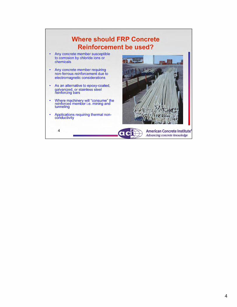
4

5

6
It must be noted that, while the member does not exhibit ductility, it has extreme deformability. For an FRP rupture failure, the beam will fail without warning, however, there will be large deflections and crack widths prior to the rupture of the bar.

7
Types of FRP composites include: carbon fiber-reinforced polymer (CFRP), aramid fiber-reinforced polymer (AFRP), and glass fiber-reinforced polymer (GFRP).
FRP material’s mechanical behavior is characterized as “linear-elastic to failure”. A typical ultimate stress and strain value is shown here for CFRP, AFRP, and GFRP reinforcing bars. However, the ultimate stress and strain values for each individual FRP material depend on the manufacturing process, type of fiber, type of resin, fiber volume, loading type, and environmental condition.
Steel reinforcing bar is often expressed as “linear elastic-plastic” where the material yields but then continues to carry load.
This difference in mechanical behavior between FRP materials and steel is accounted for in the ACI 440 document.

8
FRP materials are characterized as linear elastic to failure and thus have no yield point or yield strain value.
9
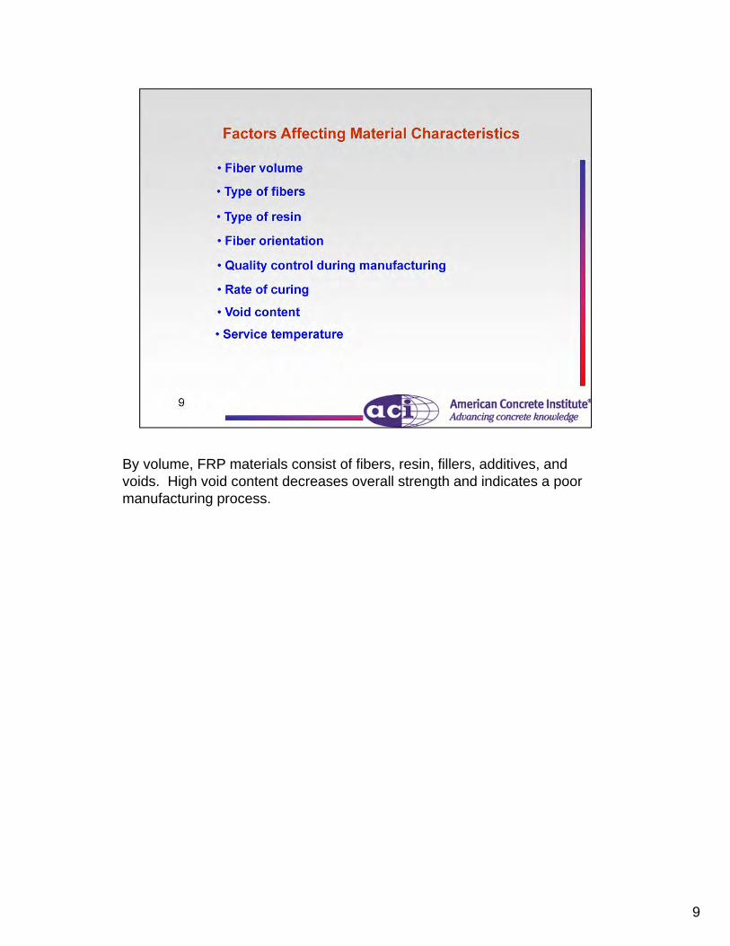
By volume, FRP materials consist of fibers, resin, fillers, additives, and voids. High void content decreases overall strength and indicates a poor manufacturing process.

10
Typical FRP materials used in civil engineering applications are 4 to 6 times lighter than steel.

11
The longitudinal coefficient of thermal expansion is dominated by the properties of the fibers, while the transverse coefficient is dominated by the resin. Note the negative CTE values for CFRP and AFRP. The carbon and aramid fibers actually shrink when heated.
Note the transverse CTE is quite high for carbon as compared to the longitudinal value. Differences in CTE between FRP materials and concrete can play an important role in determining cracking due to temperature increases. This could cause transverse cracking if large FRP bars are used.Concrete is considered isotropic and thus has the same CTE value in the longitudinal and transverse direction.

12
Given the wide range of glass transition temperatures, designers should be aware of the specific Tg value for a given resin. Tg values are typically higher for epoxy [365 to 465o F (185 to 240oC)]; however, epoxies are not commonly used with FRP reinforcing bars.
Vinylester and polyester resins are thermoset resins that do not soften, but rather decompose upon heating.
Thermoplastic resins soften or melt upon heating and are characterized by Tg or the melting temperature, Tm.
On the graph above, E is the elastic modulus of a thermoset resin.

13
The use of FRP reinforcement is not recommended for structures in which fire resistance is essential to maintain structural integrity.
FRP bars are somewhat protected by concrete and will not burn due to a lack of oxygen. Smoke generation can be a concern for exposed bars. Increased temperatures in FRP reinforced concrete will cause larger crack widths and larger deflections.

14

15
Shown here are various types of FRP concrete reinforcing products. An FRP grid is shown on the far left.
16
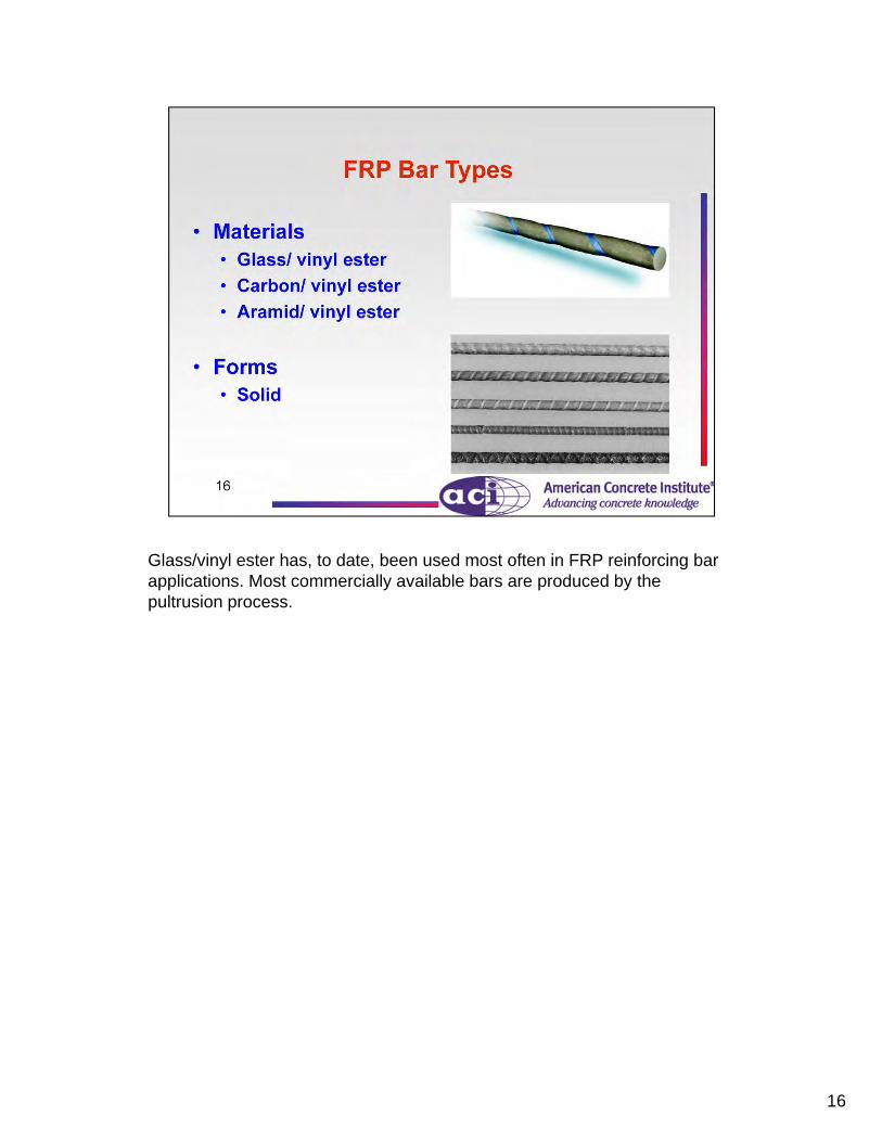
Glass/vinyl ester has, to date, been used most often in FRP reinforcing bar applications. Most commercially available bars are produced by the pultrusion process.

17
Surface deformation patterns for commercially available FRP bars:
(a) ribbed, (b) sand-coated, and (c) wrapped and sand-coated.

18
ACI 440.5-08 and 440.6-08 are the only two specifications written in mandatory language for FRP bars.

19
Some of the major advantages of FRP materials over steel.

20
FRP materials are linear-elastic to failure and thus do not yield. They do however have large ultimate strains, generally on the order of 1.5%, which gives the member a good amount of deformability. This plays an important role in the behavior and design of FRP reinforcing bars.
Items such as UV light susceptibility, moisture, and alkaline environments are accounted for in the final design.
Appropriate resin selections, as well as concrete cover, can mitigate issues such as smoke production.

21

22

23
These guaranteed tensile properties provide a 99.87% probability that the indicated values are exceeded by similar FRP bars, provided at least 25 specimens are tested.Standard deviation is a statistical quantity that is defined as a measure of dispersion of a population. In this case, the population is the tensile strength of tested FRP bars.

24
Typical compressive modulus and strength values are lower than corresponding tensile values. The behavior of FRP in compression has not been studied extensively, and at this time, ACI Committee 440 cannot recommend its use as primary compression reinforcing. Currently, there are several studies investigating the performance of compression members reinforced with FRP bars.
The interlaminar shear strength is governed by the polymer matrix, which is considerably weaker than the fibers.

25
Bond behavior is resin controlled and thus subject to environmental degradation. In FRP grids, bond is not an issue, but shear transfer is an issue.

26
The primary load carrying material of an FRP bar is the fiber. The fibers are susceptible to the creep rupture failure. Glass is a very viscous fluid and therefore is the most susceptible to the creep rupture failure.

27
While the stress limits appear to be quite low and do not allow the designer to take advantage of the higher strength of the bar, it should be noted that the stress limits are evaluated at service levels and only for permanent loads.
Carbon is the least susceptible to creep rupture but is unfortunately the most costly fiber of the group. Generally speaking it is cost prohibitive to use carbon bars in new construction applications.

28

29

30
One of the main selling points for GFRP bars are their potential long-term durability. This is also one of the most controversial and esoteric aspects of the material. There is little debate over the short-term performance of GFRP bars. We can build beams, load them, and measure their performance in real time. Debate centers on accelerated aging methodology that attempts to predict a residual end of service life strength and the accuracy of the accelerated aging methods.
While GFRP bars are not degraded by the mechanisms that would typically degrade steel reinforcing bar, it is possible for e-glass fibers to be degraded by alkaline solutions. It’s well understood that concrete is an alkaline solution.
Therefore, much research has centered on proper resin selection that will encapsulate the e-glass fibers and protect them from potential alkaline degradation.
On the left we see a microscopic view of the end of a GFRP bar. We see the individual glass fibers, a resin rich surface and kernels of sand on the surface of the reinforcing bar. On the right we see an enlarged section showing individual glass fibers and how they can be encapsulated in the resin. Definitive research has shown that a vinyl ester resin should be used. Vinyl ester resin exhibits greater elongation under strain and helps eliminate micro-cracks that are potential avenues for alkaline degradation of the glass fibers.

31

32

33
Actual diameters will vary slightly from one manufacturer to another. Nominal diameters are used to rate the bars and should be used in design calculations.

34
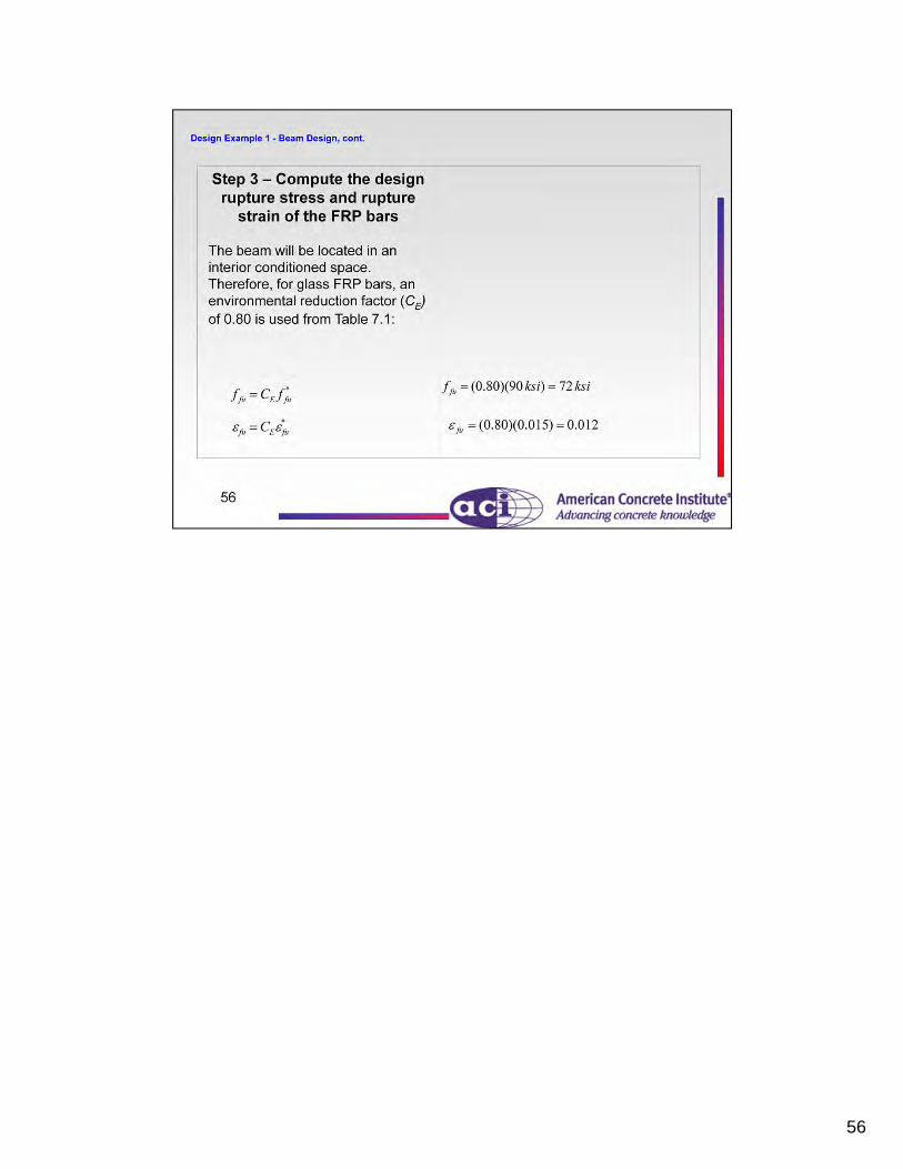
FRP design material properties take into account environmental factors through an environmental reduction factor, CE.

35
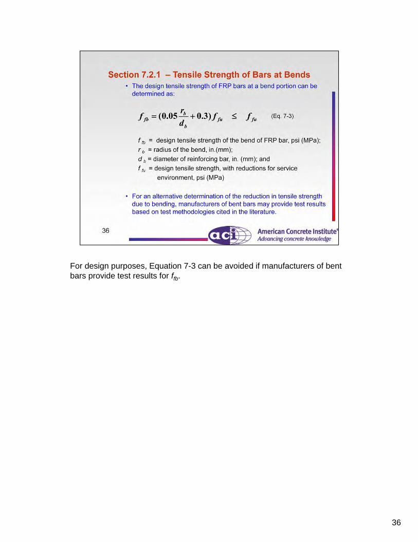
36
For design purposes, Equation 7-3 can be avoided if manufacturers of bent bars provide test results for ffb.

37

38
Bridge deck replacement for the Pierce Street Bridge in Lima, Ohio, USA.

39
Because FRP bars do not yield, a member governed by FRP rupture will have a “brittle” failure. The failure will be “sudden” and without warning and will not carry any load.
While the failure mode of an FRP rupture failure is not ductile, the member will exhibit a great deal of deformability. By the time the FRP bar ruptures, the effective moment of inertia (discussed later) will be a small fraction of the gross moment of inertia, resulting in very large deflections and a great degree of curvature. As mentioned earlier, the rupture strain of the FRP bar is fairly high and will result in excessive strains in the adjacent concrete leading to large cracks.

40

41
42
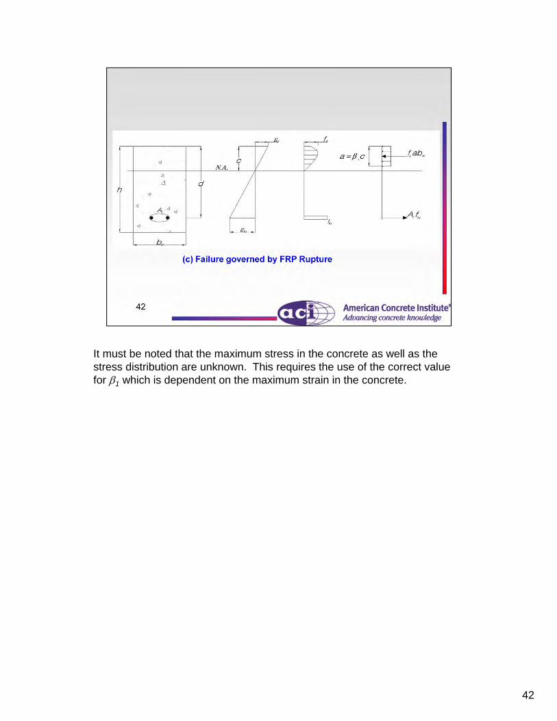
It must be noted that the maximum stress in the concrete as well as the stress distribution are unknown. This requires the use of the correct value for 1 which is dependent on the maximum strain in the concrete.

43

44
The factored moment, Mu, is due to all applicable loads such as dead load, live load, wind load, etc.
45

46

47

48
The actual neutral axis depth c is a function of the stress distribution and is not easily calculated so it is conservative to use a maximum value for c = cb.

49

50

51

52

53

54
55
56

57

58
59
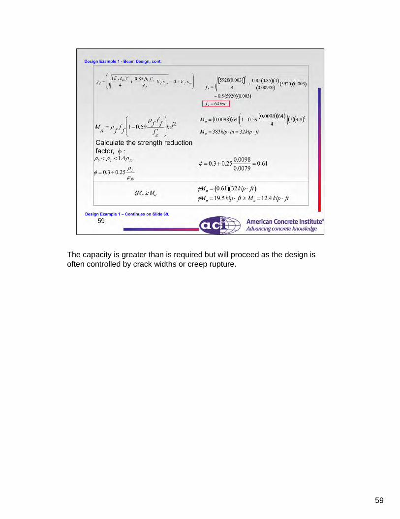
The capacity is greater than is required but will proceed as the design is often controlled by crack widths or creep rupture.

60

61
Due to the inherent differences between FRP and steel reinforcement, a separate deflection analysis of FRP RC beams is needed.
Excessively large cracks might result from large strains in the FRP bar, which could cause creep rupture limits to be violated.

62
Crack width determination based on Gergely-Lutz equation.
Minimum values of crack widths are relaxed because FRP material will not corrode.
The design guide recommendations are based on the Japanese and Canadian Code for cracking limits based on structures exposed to aggressive environments and designed to be watertight.
The kb factor accounts for how well the bar bonds to the adjacent concrete as compared to uncoated steel. When the bond is inferior to steel it will be less effective in restraining the crack width and hence the kb factor is greater than 1.0. The consensus of the committee is that if the exact value of kb is unknown, it should be conservatively taken as 1.4.

63
In general, the ACI 318 provisions for deflection control are concerned with deflections that occur at service levels under immediate and sustained static loads and do not apply to dynamic loads, such as earthquakes, transient winds, or vibration of machinery. Deflections in FRP reinforced members are much more sensitive to variables such as stiffness, brittle-elastic nature, and bond characteristics, and therefore ACI 440.1R-06 requires that the direct method be used.

64

65

66

67

68

69

70

71

72

73

74

75

76