TEST OF A MICROMEGAS DETECTOR FOR THE MUON TRACKING CHAMBERS
The Assembly of ATLAS Muon chambers @NIKHEF
34
Marcel Vreeswijk (NIKHEF) • The NIKHEF Muon Mission • Chamber assembly • Assembly QA • Assembly QC • Summary, Status and Plans The Assembly of The Assembly of ATLAS Muon ATLAS Muon chambers chambers @NIKHEF @NIKHEF
-
Upload
joseph-richards -
Category
Documents
-
view
47 -
download
1
description
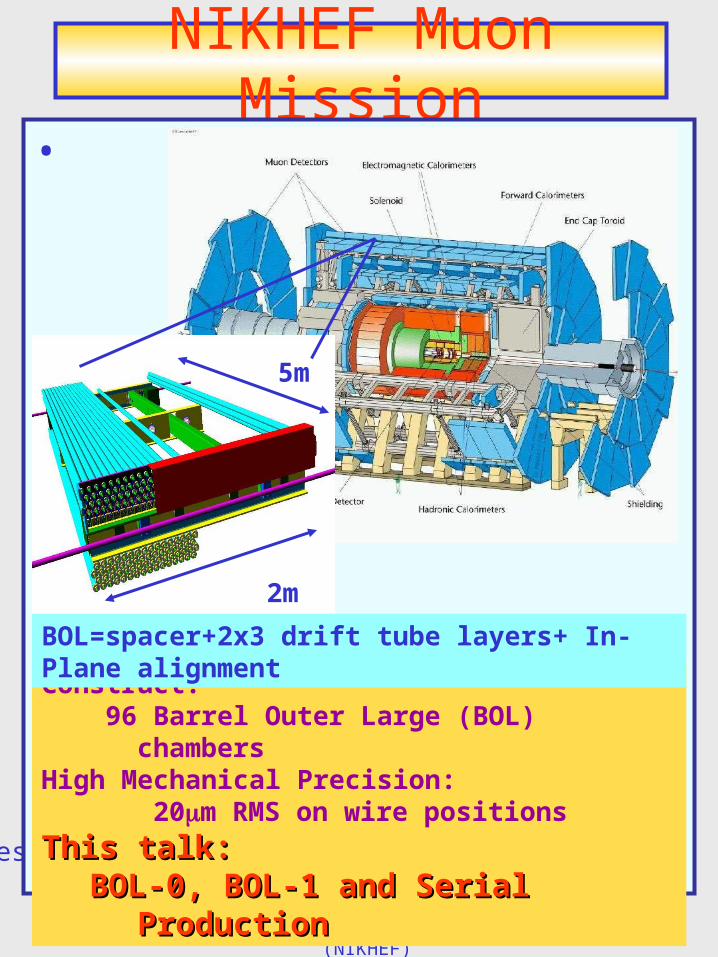
The Assembly of ATLAS Muon chambers @NIKHEF. The NIKHEF Muon Mission Chamber assembly Assembly QA Assembly QC Summary, Status and Plans. 5m. 2m. NIKHEF Muon Mission. BOL=spacer+2x3 drift tube layers+ In-Plane alignment. Construct: 96 Barrel Outer Large (BOL) chambers - PowerPoint PPT Presentation
Transcript of The Assembly of ATLAS Muon chambers @NIKHEF

Marcel Vreeswijk (NIKHEF)
• The NIKHEF Muon Mission• Chamber assembly • Assembly QA• Assembly QC• Summary, Status and Plans
The Assembly of The Assembly of ATLAS Muon chambersATLAS Muon chambers
@NIKHEF@NIKHEF
The Assembly of The Assembly of ATLAS Muon chambersATLAS Muon chambers
@NIKHEF@NIKHEF
Marcel Vreeswijk (NIKHEF)
NIKHEF Muon Mission
West side has expansion length o 0.1m in Xras
•
s
Construct: 96 Barrel Outer Large (BOL) chambers
High Mechanical Precision: 20m RMS on wire positions
This talk: This talk: BOL-0, BOL-1 and Serial ProductionBOL-0, BOL-1 and Serial Production
2m
5m
BOL=spacer+2x3 drift tube layers+ In-Plane alignment
Marcel Vreeswijk (NIKHEF)
Assembly Station
West side has expansion length o 0.1m in Xras
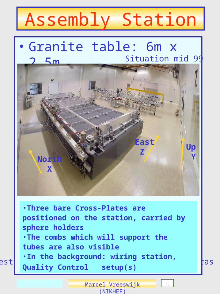
• Granite table: 6m x 2.5m
•Three bare Cross-Plates are positioned on the station, carried by sphere holders•The combs which will support the tubes are also visible•In the background: wiring station, Quality Control
setup(s)
Situation mid 99
North X
East Z
Up Y
s
Marcel Vreeswijk (NIKHEF)
Chamber Assembly
West side has expansion length o 0.1m in Xras
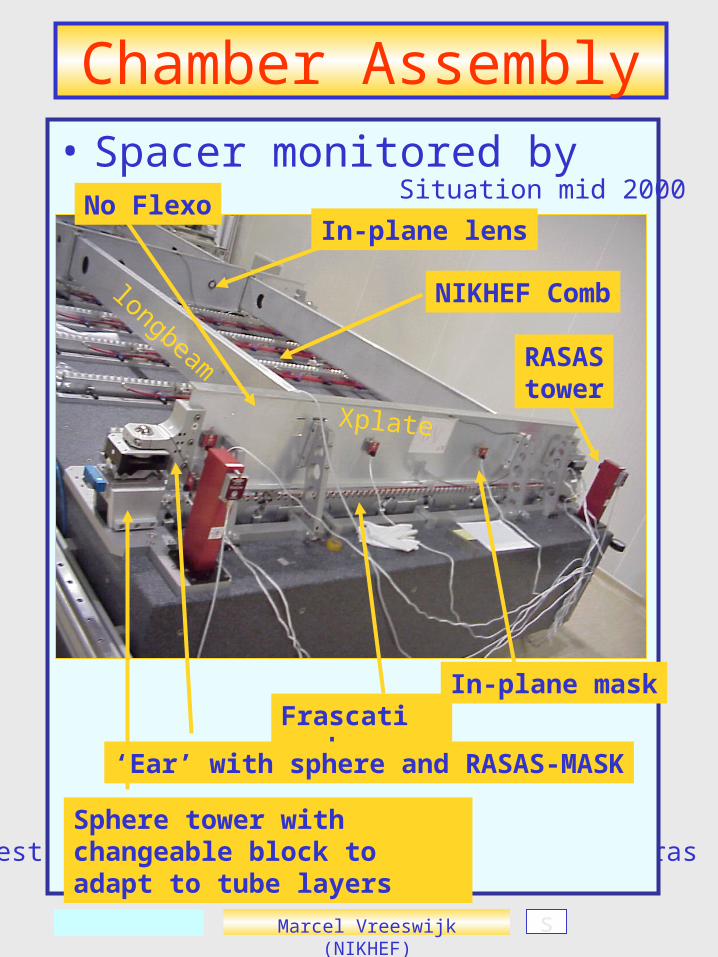
• Spacer monitored by RASASSituation mid 2000
Sphere tower with changeable block to adapt to tube layers
NIKHEF Comb
Frascati comb
RASAStower
‘Ear’ with sphere and RASAS-MASK
In-plane mask
In-plane lens
Xplate
longbeam
s
No Flexo

Marcel Vreeswijk (NIKHEF)
‘RASAS’ Monitors
s
Monitor positioning during assembly by RASAS monitor:
Changeable blocks
Support ‘ear’ which holds the mask
The RASAS tower which holds the camera and lens
xplate
Block 1
Block 2
Block 3
Ypitch 26.011mm
Scatter 5um
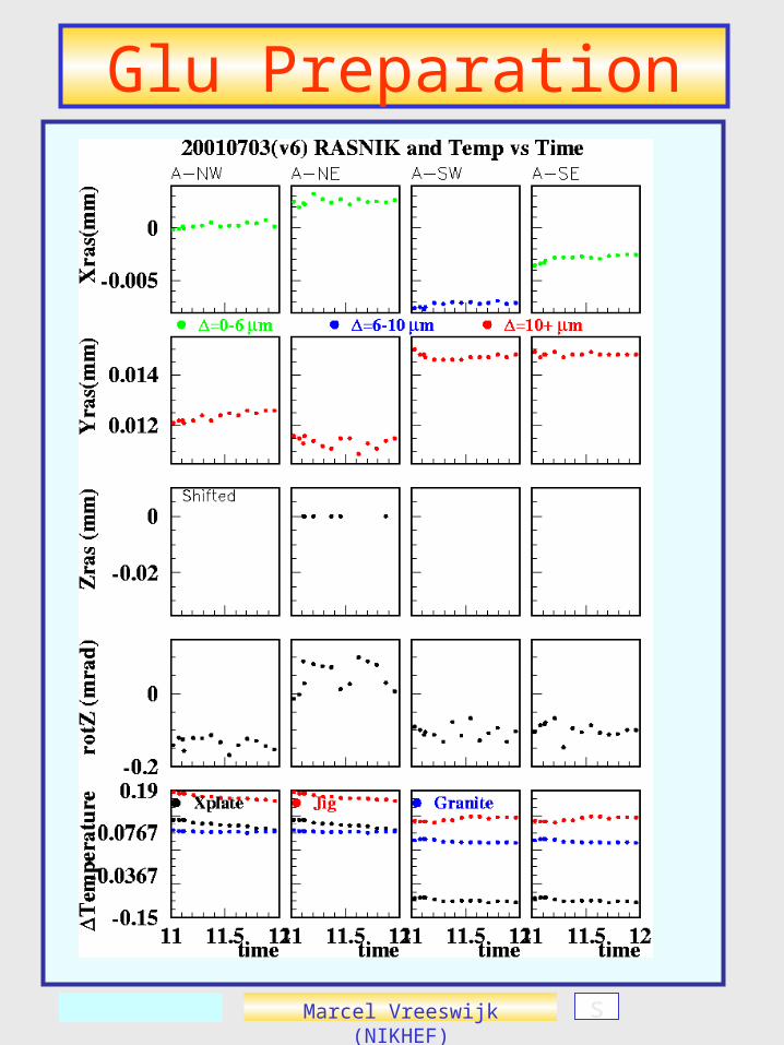
Measured temperatures explain (small) drift
Marcel Vreeswijk (NIKHEF)
Temperature Stability
s
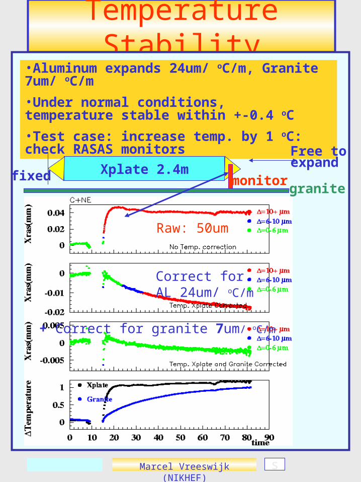
•Aluminum expands 24um/ oC/m, Granite 7um/ oC/m
•Under normal conditions, temperature stable within +-0.4 oC
•Test case: increase temp. by 1 oC: check RASAS monitors
Xplate 2.4mfixed monitorgranite
Free toexpand
Raw: 50um
Correct for AL 24um/ oC/m
+ Correct for granite 7um/ oC/m
Marcel Vreeswijk (NIKHEF)
Tube Placing
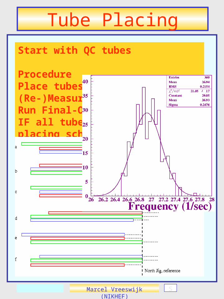
Start with QC tubes
ProcedurePlace tubes on combs (Re-)Measure Wire FrequencyRun Final-OK programIF all tubes OK, follow placing scheme
s
Marcel Vreeswijk (NIKHEF)
Glu Preparation
s
Marcel Vreeswijk (NIKHEF)
Glu Preparation
s
Marcel Vreeswijk (NIKHEF)
Glu Preparation
s
Marcel Vreeswijk (NIKHEF)
Glu Preparation
s

Marcel Vreeswijk (NIKHEF)
Glu Preparation
s

Marcel Vreeswijk (NIKHEF)
Glu Preparation
s

Marcel Vreeswijk (NIKHEF)
Glu Preparation
s

Marcel Vreeswijk (NIKHEF) s
Tube diameter 3cmDistance 65m
tube
tube tube
tubetube
Side rope Central rope
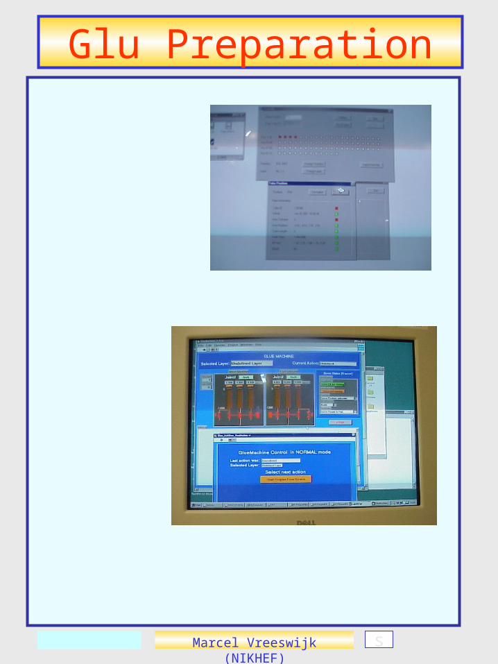
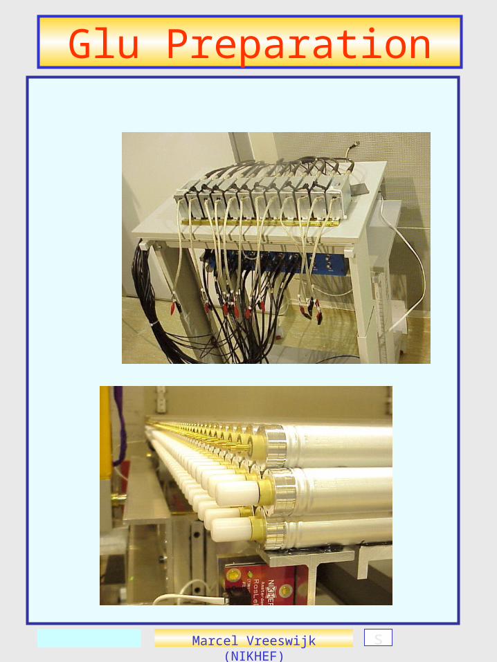
Gluing (BOL-0)2 x glue units2x3 glue nozzles
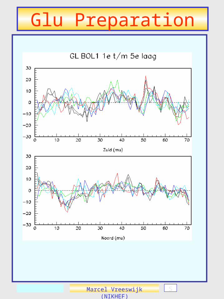
•Tube layer 1 central ropes•Spacer glued on layer 1•Tube layer 2 central ropes•Spacer+1 glued on layer 2•Tube layer 3 central+side ropes•Spacer+1+2 on layer 3•etc….
Marcel Vreeswijk (NIKHEF)
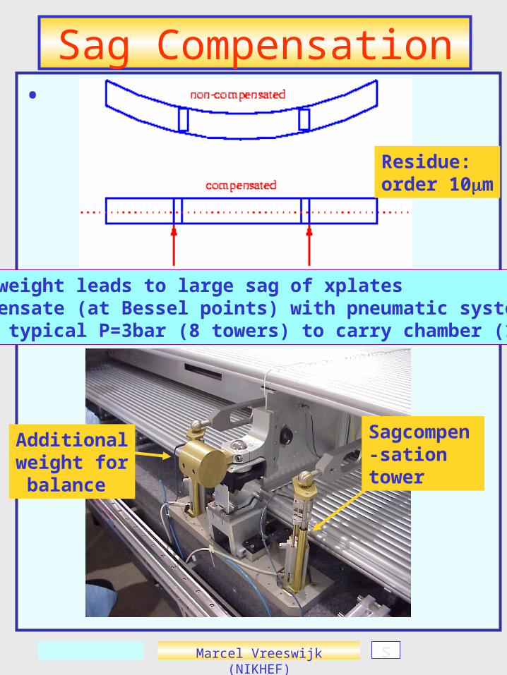
Sag Compensation•
Sagcompen-sation tower
Additionalweight for balance
s
•Own weight leads to large sag of xplates•Compensate (at Bessel points) with pneumatic system•Need typical P=3bar (8 towers) to carry chamber (150kg)
Residue:order 10m
Marcel Vreeswijk (NIKHEF)
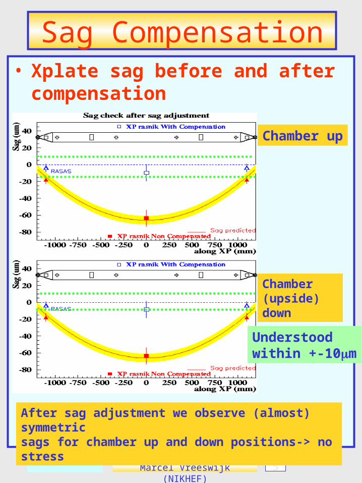
Sag Compensation• Xplate sag before and after
compensation
s
After sag adjustment we observe (almost) symmetric sags for chamber up and down positions-> no stress
Chamber up
Chamber (upside) down
Understoodwithin +-10m
Marcel Vreeswijk (NIKHEF)
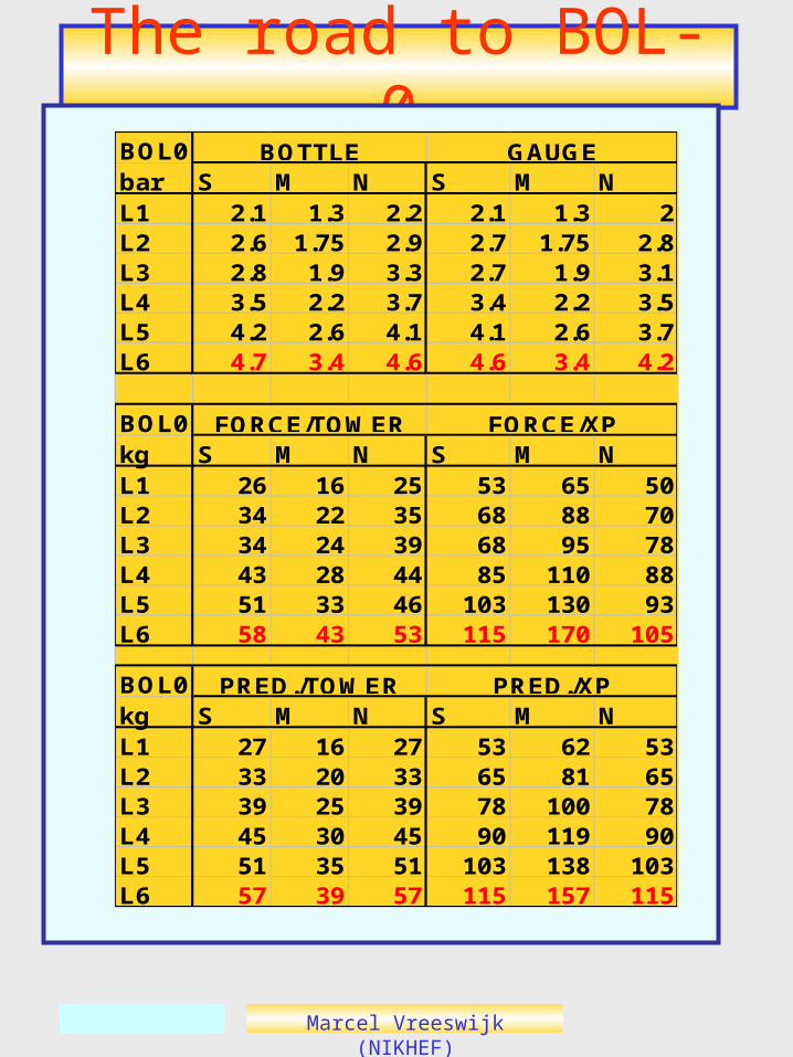
The road to BOL-0BOL0bar S M N S M NL1 2.1 1.3 2.2 2.1 1.3 2L2 2.6 1.75 2.9 2.7 1.75 2.8L3 2.8 1.9 3.3 2.7 1.9 3.1L4 3.5 2.2 3.7 3.4 2.2 3.5L5 4.2 2.6 4.1 4.1 2.6 3.7L6 4.7 3.4 4.6 4.6 3.4 4.2
BOL0kg S M N S M NL1 26 16 25 53 65 50L2 34 22 35 68 88 70L3 34 24 39 68 95 78L4 43 28 44 85 110 88L5 51 33 46 103 130 93L6 58 43 53 115 170 105
BOL0kg S M N S M NL1 27 16 27 53 62 53L2 33 20 33 65 81 65L3 39 25 39 78 100 78L4 45 30 45 90 119 90L5 51 35 51 103 138 103L6 57 39 57 115 157 115
PRED./TOWER PRED./XP
BOTTLE GAUGE
FORCE/TOWER FORCE/XP

Marcel Vreeswijk (NIKHEF)
Gluing BOL-0
s
Glue: Days needed1 Glue Spacer1 1st layer+platforms1 spacer on 1st1 2nd layer+spacer4 layersTotal <10 days
Marcel Vreeswijk (NIKHEF)
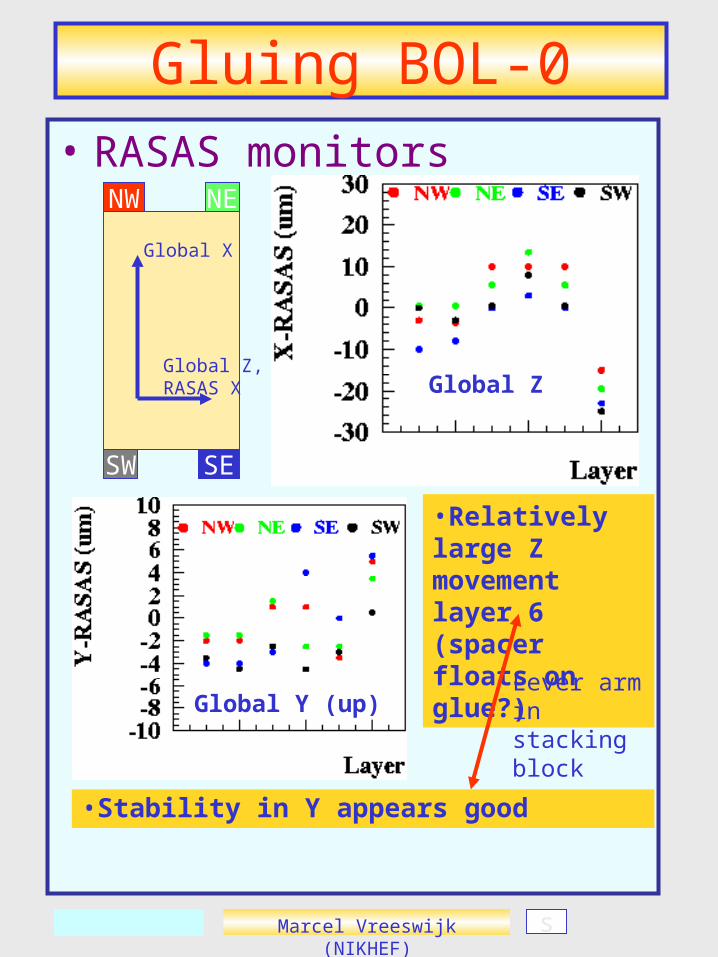
Gluing BOL-0• RASAS monitors
SE
NW
SW
NE
Global Z,RASAS X
Global X
•Stability in Y appears good
•Relatively large Z movement layer 6 (spacer floats on glue?)
s
Lever arm in stacking block
Global Z
Global Y (up)
Marcel Vreeswijk (NIKHEF)
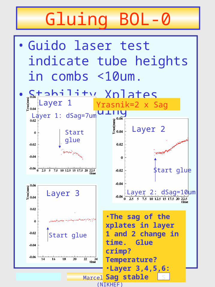
Gluing BOL-0• Guido laser test indicate tube
heights in combs <10um.
• Stability Xplates during gluing
Start glue
Start glue
Layer 2
Layer 3
Yrasnik=2 x Sag
Start glue
Layer 1
Layer 1: dSag=7um
Layer 2: dSag=10um
•The sag of the xplates in layer 1 and 2 change in time. Glue crimp? Temperature?•Layer 3,4,5,6: Sag stable
s
Marcel Vreeswijk (NIKHEF)
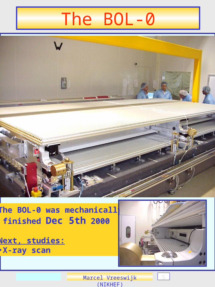
The BOL-0
s
The BOL-0 was mechanically
finished Dec 5th 2000
Next, studies:•X-ray scan
Marcel Vreeswijk (NIKHEF)
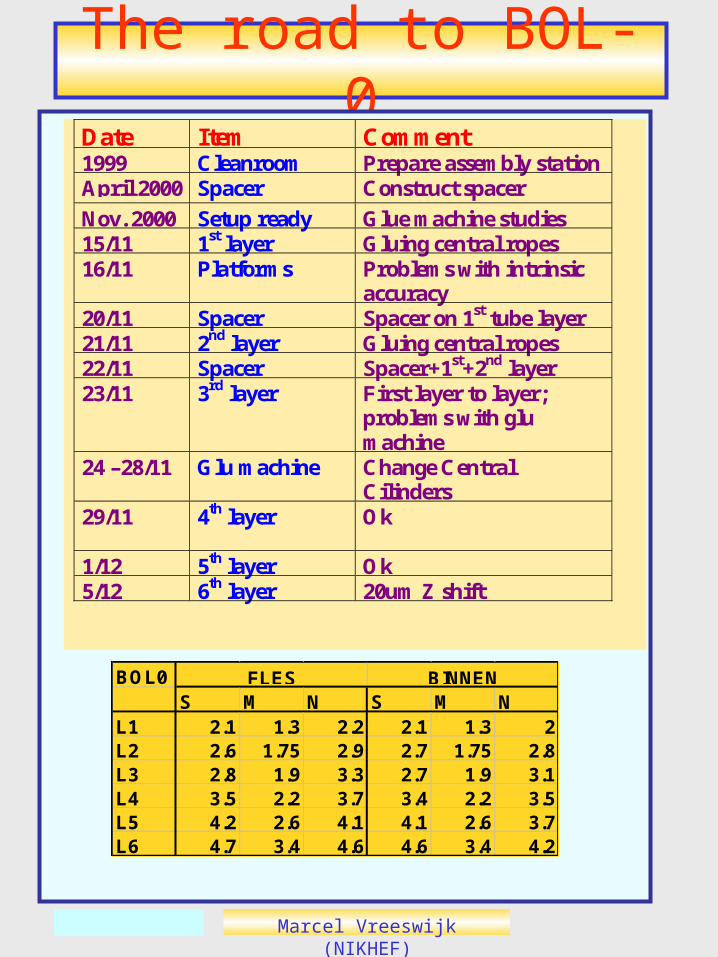
The road to BOL-0Date Item Comment1999 Cleanroom Prepare assembly stationApril 2000 Spacer Construct spacer
Nov. 2000 Setup ready Glue machine studies15/11 1st layer Gluing central ropes16/11 Platforms Problems with intrinsic
accuracy20/11 Spacer Spacer on 1st tube layer21/11 2nd layer Gluing central ropes22/11 Spacer Spacer+1st+2nd layer23/11 3rd layer First layer to layer;
problems with glumachine
24 –28/11 Glu machine Change CentralCilinders
29/11 4th layer Ok
1/12 5th layer Ok5/12 6th layer 20um Z shift
BOL0S M N S M N
L1 2.1 1.3 2.2 2.1 1.3 2L2 2.6 1.75 2.9 2.7 1.75 2.8L3 2.8 1.9 3.3 2.7 1.9 3.1L4 3.5 2.2 3.7 3.4 2.2 3.5L5 4.2 2.6 4.1 4.1 2.6 3.7L6 4.7 3.4 4.6 4.6 3.4 4.2
FLES BINNEN
Marcel Vreeswijk (NIKHEF)
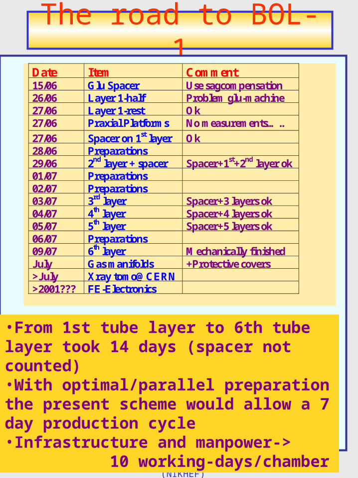
The road to BOL-1Date Item Comment15/06 Glu Spacer Use sagcompensation26/06 Layer 1-half Problem glu-machine27/06 Layer 1-rest Ok27/06 Praxial Platforms No measurements…..
27/06 Spacer on 1st layer Ok28/06 Preparations29/06 2nd layer + spacer Spacer+1st+2nd layer ok01/07 Preparations02/07 Preparations03/07 3rd layer Spacer+3 layers ok04/07 4th layer Spacer+4 layers ok05/07 5th layer Spacer+5 layers ok06/07 Preparations09/07 6th layer Mechanically finishedJuly Gas manifolds +Protective covers>July Xray tomo@CERN>2001??? FE-Electronics
•From 1st tube layer to 6th tube layer took 14 days (spacer not counted)•With optimal/parallel preparation the present scheme would allow a 7 day production cycle•Infrastructure and manpower->
10 working-days/chamber
Marcel Vreeswijk (NIKHEF) s
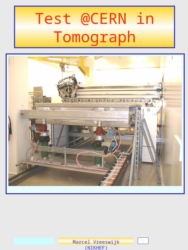
Test @CERN inTomograph
Marcel Vreeswijk (NIKHEF) s
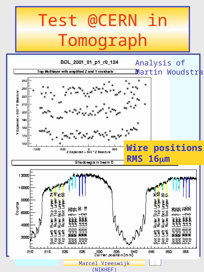
Test @CERN inTomograph
Wire positionsRMS 16m
Analysis of Martin Woudstra
Marcel Vreeswijk (NIKHEF)
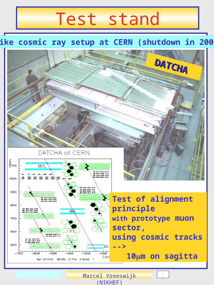
Test stand
s
DATCHADATCHA
Like cosmic ray setup at CERN (shutdown in 2000)
Test of alignment principle with prototype muon sector,using cosmic tracks --> 10m on sagitta

Marcel Vreeswijk (NIKHEF)
Test stand @NIKHEF
s
Tests five chambers using cosmic rays (end 2001)•Checks wire positions•Checks DCS + DAQ
Trigger modules, consisting of 50cm iron, with two layers scintillator. Ecut>1GeVExpected rate: 100Hz
Marcel Vreeswijk (NIKHEF)
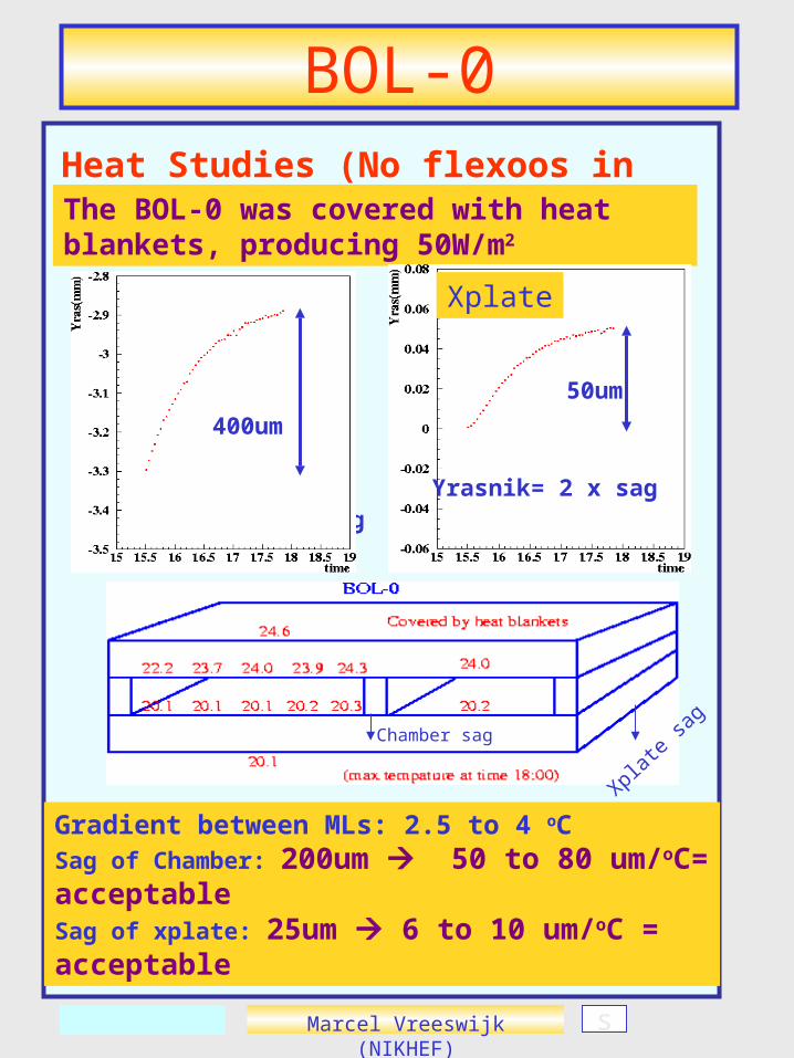
BOL-0Heat Studies (No flexoos in BOL-0)
s
Inplane
Yrasnik= 2 x sag
The BOL-0 was covered with heat blankets, producing 50W/m2
Gradient between MLs: 2.5 to 4 oCSag of Chamber: 200um 50 to 80 um/oC= acceptableSag of xplate: 25um 6 to 10 um/oC = acceptable
400um
Yrasnik= 2 x sag
Xplate
50um
Chamber sag
Xplate
sag

Marcel Vreeswijk (NIKHEF)
Status and Plans
• Finished BOL-0 at NIKHEF (dec. 5th 2000) with high mechanical precision (16m RMS)
• Quality Control automated
• Production of tubes started May 2001
• Now: Produce first chamber
• Expect to finalize 10 chambers by end 2001
• Produce 1chamber/2weeks: 24 chambers/year -> finish summer 2005
• Late 2002, evaluate need to speed up chamber production (work weekends and/or two gluing steps/day)
• Cosmic ray setup operational end 2001
Marcel Vreeswijk (NIKHEF)
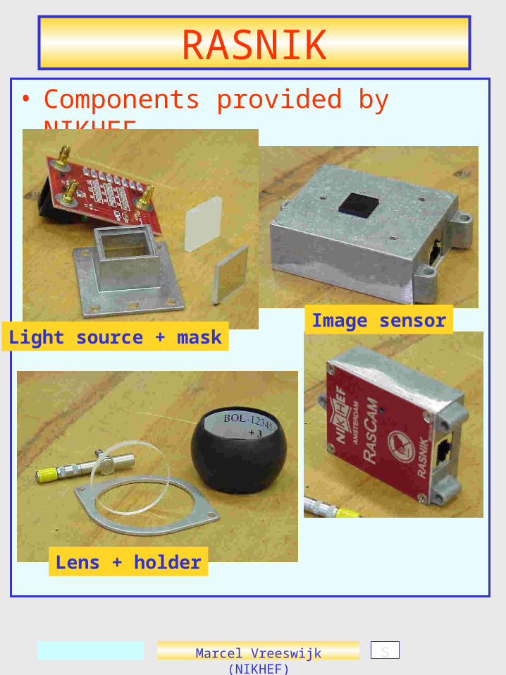
RASNIK• Components provided by NIKHEF
s
Light source + maskImage sensor
Lens + holder
Marcel Vreeswijk (NIKHEF)
Precision Mechanics
West side has expansion length o 0.1m in Xras
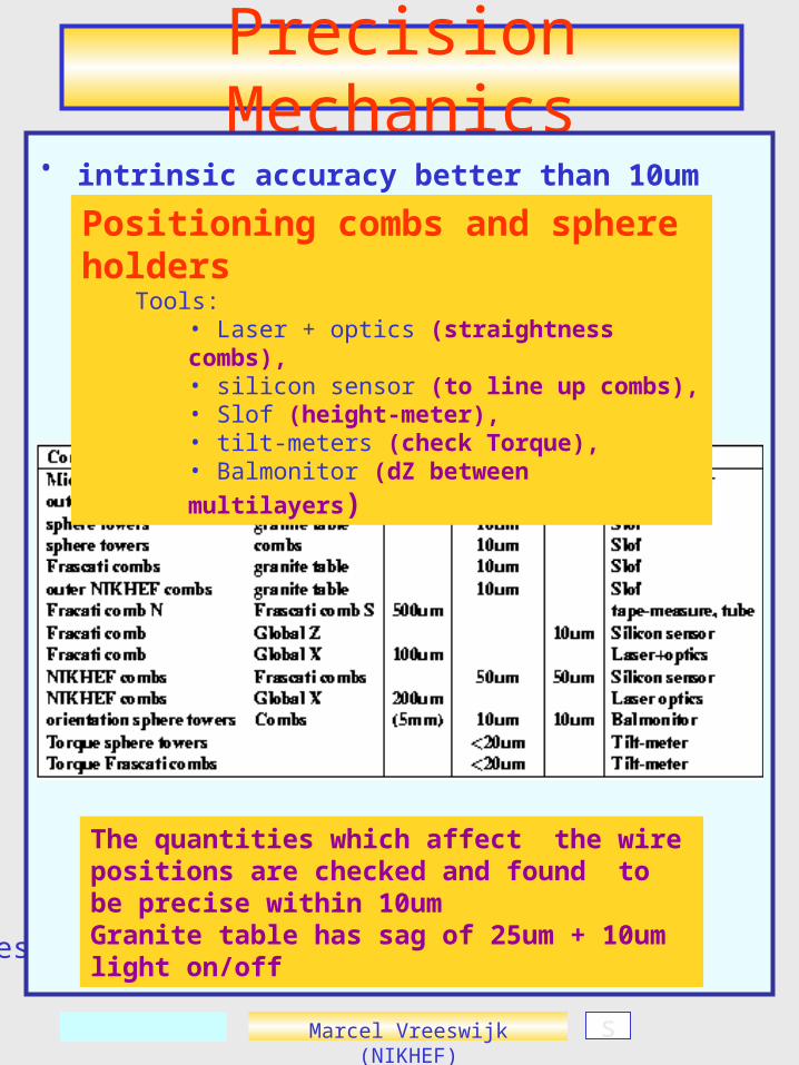
• intrinsic accuracy better than 10um
The quantities which affect the wire positions are checked and found to be precise within 10umGranite table has sag of 25um + 10um light on/off
s
Positioning combs and sphere holders Tools:
• Laser + optics (straightness combs),• silicon sensor (to line up combs),• Slof (height-meter), • tilt-meters (check Torque),• Balmonitor (dZ between multilayers)
Marcel Vreeswijk (NIKHEF)
Assembly Station
West side has expansion length o 0.1m in Xras
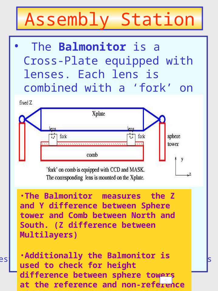
• The Balmonitor is a Cross-Plate equipped with lenses. Each lens is combined with a ‘fork’ on the combs to form a RASNIK system
•The Balmonitor measures the Z and Y difference between Sphere tower and Comb between North and South. (Z difference between Multilayers)
•Additionally the Balmonitor is used to check for height difference between sphere towers at the reference and non-reference side (West/East)
s

Marcel Vreeswijk (NIKHEF)
Gluing BOL-0• Result for side (106) and central (103) ropes
Central rope
Central rope
Central rope
Central rope
Central rope,sometimes bad(stability glue unit?)
tube