THE ART OF ERGONOMICS - Atlas Copco · 4.6 Strip trigger ... 14.2 Orbital and random orbital...
40
THE ART OF ERGONOMICS
Transcript of THE ART OF ERGONOMICS - Atlas Copco · 4.6 Strip trigger ... 14.2 Orbital and random orbital...

THE ART OFERGONOMICS

2 T H E A R T O F E R G O N O M I C S
CONTENTS
1. What is ergonomics? .........................................................................................4
2. Why ergonomics? ..............................................................................................4
3. Handle design ....................................................................................................5 3.1 Bow handle ...................................................................................................6 3.2 Pistolgrip handles ........................................................................................7 3.3 Straight handles ...........................................................................................8 3.3.1 Screwdrivers and drills ......................................................................8 3.3.2 Grinders and angle nutrunners .........................................................9
4. Triggers .............................................................................................................. 10 4.1 Finger triggers ............................................................................................ 10 4.2 Two finger triggers .................................................................................... 10 4.3 Thumb triggers .......................................................................................... 11 4.4 Lever triggers ............................................................................................. 11 4.5 Push start .................................................................................................... 11 4.6 Strip trigger ................................................................................................ 11
5. Torque reaction in fastening tools ..................................................................12 5.1 Impact wrenches ........................................................................................12 5.2 Impulse tools ..............................................................................................12 5.3 Direct driven tools 5.3.1 Pneumatic shut-off tools ..................................................................13 5.3.2 Electric nutrunners ...........................................................................13 5.4 Reaction bars .............................................................................................. 14 5.5 Balancers ....................................................................................................15
6. Sound ................................................................................................................16 6.1 What is sound? ...........................................................................................16 6.2 How does sound affect us? .......................................................................16 6.3 Measurement to establish noise emission values ..................................17 6.4 Health and safety regulations ...................................................................17 6.5 The Physical Agents (Noise) Directive ......................................................17
7. Sources of noise in pneumatic tools .............................................................19 7.1 Process noise .............................................................................................. 19 7.2 Air flow noise .............................................................................................. 19 7.3 Vibration induced noise ............................................................................. 19

3T H E A R T O F E R G O N O M I C S
8. Methods of reducing noise .............................................................................20 8.1 Process noise..............................................................................................20 8.2 Air flow noise .............................................................................................21 8.3 Vibration induced noise .............................................................................22 8.4 Noise control at the workplace .................................................................22
9. Vibration in handheld tools ............................................................................23 9.1 What is vibration? ......................................................................................23 9.2 Why is vibration a concern? ......................................................................23 9.3 Measurement to establish vibration emission values ............................24 9.4 Health and safety regulations ...................................................................24 9.5 The Physical Agents (Vibration) Directive ................................................25
10. Source of vibration ..........................................................................................26
11. Reducing vibration in handheld tools ............................................................27 11.1 Grinders .....................................................................................................27 11.2 Die grinders ...............................................................................................27 11.3 Angle and vertical grinders ......................................................................27 11.4 Turbo grinders ...........................................................................................27 11.5 Percussive tools ........................................................................................28 11.6 Chipping hammers ...................................................................................29 11.7 Riveting hammers ....................................................................................29 11.8 Bucking bars ..............................................................................................29 11.9 Scalers .......................................................................................................29 11.10 Impact wrenches and impulse tools .....................................................30
12. Lubrication-free motors...................................................................................31
13. Dust control ......................................................................................................32 13.1 Why control dust? ....................................................................................32 13.2 Health ........................................................................................................32 13.3 How to control dust .................................................................................32
14. Extraction systems for tools ...........................................................................33 14.1 Disc sanders .............................................................................................33 14.2 Orbital and random orbital sanders .......................................................33 14.3 Depressed center grinders ......................................................................33 14.4 Straight grinders ......................................................................................33 14.5 Die grinders ..............................................................................................33 14.6 Diamond tipped grinders ........................................................................33 14.7 Drills ..........................................................................................................33 14.8 Chipping hammers ..................................................................................34
15. Vacuum sources ...............................................................................................35 15.1 Installation of extraction systems...........................................................36

4 T H E A R T O F E R G O N O M I C S
1. WHAT IS ERGONOMICS?Ergonomics is a relatively new science combining knowledge mainly from three disciplines: human science, work-related sciences and production science.
Ergonomics describes a complex interaction between the operator and his/her working environment. Power tools with good ergonomic design are an essential element with regard to achieving a good ergonomic workplace. At the same time they are only one of the several contributing factors involved.
2. WHY ERGONOMICS?In today´s competitive market, the drive to achieve high pro-ductivity with high quality production is strong.Many companies now realize the important contribution that ergonomic workstations can make towards achieving this goal.
More and more companies have come to realize that work related disorders cost a lot of money. Not only for the reha-bilitation of injured persons but also for lost productivity and for quality problems related to workplaces with poor ergo-nomics. Studies have been published that indicate that those costs are often several times greater than the direct cost for rehabilitation. With this taken into account, good ergonomic design of workplaces and tools can save companies a great deal of money.
Workstations and working practices should be designed toavoid exposing the operator to unnecessary physical load,noise, vibration and dust.
Handheld tools are of particular importance because they form the direct link between operator and process.
The aim of this pocket guide is to give the reader an under-standing of how handheld tools can be designed to avoid un-necessary strain on the operator.

5T H E A R T O F E R G O N O M I C S
3. HANDLE DESIGNThe handle is the interface between the operator and the tool. All forces associated with the task are transmitted between the hand and handle. An ergonomic handle design is vital in producing a tool that places the minimum strain on the opera-tor.
To ensure the optimum position for transmitting forces be-tween hand and arm, the wrist must be kept straight. It is also important to reduce, as far as possible, the twisting and bend-ing forces applied to the wrist. As there are many different working positions most tools are available with a selection of handle types.
All tools should be designed to have a high power-to-weightratio. Heavy tools not only put a higher load on the wrist, they also make precision tasks more difficult.
This section looks at the design of the different handles andexplains the applications they should be used for.
There are many different handle designs. It is important to choose the best design for every applica-tion.

6 T H E A R T O F E R G O N O M I C S
3.1 Bow handle
This type of handle is used to transmit high feed forces with-out causing a torque in the wrist. To achieve this, the handle should be designed to ensure the feed force is transmitted through the center line of arm and wrist.
The natural angle of the handgrip is independent of handsize. This angle is approximately 70 degrees.
By making the handle at this angle the muscles stabilizingthe wrist are in the optimal position.
The limitation of this design is that the weight of the tool is put in front of the hand. If used as a single handed tool it would put a high bending force on the wrist, which is undesirable.
This handle is ideal for chipping hammers and big rivetinghammers.
The bow handle is ideal for tools requiring high feed forces.

7T H E A R T O F E R G O N O M I C S
3.2 Pistol grip handles
The pistol grip handle is used to shorten the length of the tool, reducing the bending load on the wrist. Keeping the dis-tance between hand and workpiece as short as possibleallows precision tasks to be performed efficiently.
There are two different ways to design a pistol grip handle.The drill handle is used, e.g., on drills requiring high feed forces. This handle is placed in the rear of the tool allowing the use of a high grip. On, e.g., pulse tools where feed forces are normally low, the handle is moved forward placing the center of the tool weight directly above the handle. This nut-runner handle keeps the bending force on the wrist from the weight of the tool low.
The drill handle designed for the high grip should be angled to 70 degrees. This is the best angle for the wrist when trans-mitting high feed forces to the tool. In many cases though, the drill handle is also used with a low grip, e.g., when a drill is used as a screwdriver. It is therefore important to make the pistol grip handle long enough to allow a low grip.
n The high grip keeps a straight line through the arm and wrist for high feed forces.
nThe low grip is used to transmit twisting forces comfort-ably to the wrist.
For tools requiring high feed forces a high grip is preferred. For tools with only twisting forces, it is more important to have the handle in a forward position to reduce the wrist torque from the weight of the tool.
The two possible hand positions used on pistol grip handles.

8 T H E A R T O F E R G O N O M I C S
3.3 Straight handles
Handle diameters of 38 mm for men and 34 mm for women have been found to allow the strongest grip and cause the minimum strain in the hand when held. Consideration to the probable gender of the worker should be given when design-ing a tool.
The next aspect to consider is whether the tool produces a twisting torque in the hand (screwdrivers and drills) or pro-duces a levering torque on the wrist and arm (grinders and angle nutrunners).
3.3.1 Screwdrivers and drillsFor tools used in light assembly work a diameter of 34 mm should be aimed for. This is because many operators in this environment are female. As the male grip tends to be stronger, men are less affected by a small deviation from their optimum diameter.
For applications, such as drilling, where male operatorsdominate, a 38 mm handle diameter should be used.
High torque can comfortably be handled with lower grip force if the handle has an ergonomic design. The surface should have a visco-elastic coating with high friction. The texture should allow ventilation of the grip. A tapered handle allows all fingers to grip equally.
For ease of movement and to minimize loading of the wrist the tool should be kept short with the center of balance where the tool is gripped. Keeping the distance between hand and workpiece as short as possible speeds up precision tasks.
Straight handles can be used either for twisting torque or for levering torque applications.
For screwdrivers used mainly by female operators the best handle diameter is 34 mm.
For drilling, a handle diameter of 38 mm should be used.

9T H E A R T O F E R G O N O M I C S
3.3.2 Grinders and angle nutrunnersIn the case of angle nutrunners, particularlyon tools with a high torque capacity, it isimportant to ensure a secure grip on the tool.As these tools are mainly used by men a handle diameterof 38 mm is most suitable.
With die grinders the forces on the hand and wrist are often lower than with other tools but they are used over longer time periods. The comfort level for operators can be improved by making the handle from an insulating material, protecting the hand from the cold temperature of the expanding exhaust air.
On rough grinders requiring two-handed operation and high-er feed forces it is important to have an ergonomic handle design. The support handle should be adjustable.The main handle should preferably be angled allowing amore natural wrist angle. The distance from the supporthandle to the grinding spot should be kept short to reducewrist torque.
Today the grip surface on most handles is covered with a visco-elastic material. The grip is appreciated as more com-fortable, friction is improved and the handle feels less cold.
Put the support handle in the most suitable position.
Using the wheel wrench it is secured to a strong tripod support.
For angle nutrunners the handle dimeter should preferably be38 mm.
On die grinders it is important to insulate the grip surface from the cold exhaust air.
The use of visco-elastic materials in the grip surface has now be-come standard.
The GTG grinder is designed for best ergonomics.

10 T H E A R T O F E R G O N O M I C S
4. TRIGGERSThe choice of trigger is closely related to the design of the handle and the function of the tool. In the following section the different trigger types are described.
4.1 Finger triggers
Used mainly on pistol handle tools where the trigger can be operated without affecting the grip on the handle. The trigger should be designed to ensure that it is pressed with the mid-dle part of the finger. If the tip of the finger is used, tendon damage can result.
The drill handle designed for high push force has a high grip and a trigger operated with the middle finger.
The screwdriver handle designed for high torque and limited push force is often located underneath the tool body close to the center of gravity and with a trigger operated with the index finger.
This type of trigger gives very precise control over the speed of the tool. To give the operator the right “feel” when using the tool, the trigger should be designed so that increasing the pressure on the trigger increases the speed of the tool.
Finger triggers are used for frequent operation, precision tasks and where the tool needs to be positioned before it is started.
4.2 Two finger trigger
On the Tensor electric nutrunners a two finger trigger is used. This reduces the trigger forces when two fingers are used. It also increases flexibility as the trigger hand can be moved along the handle and still have a comfortable trigger for one finger operation.
On handles designed for high grip the trigger is operated with the middle finger while handles for the low grip have triggers op-erated with the index finger.
The two finger trigger on Tensor ST allows a high degree of free-dom when gripping the tool.

11T H E A R T O F E R G O N O M I C S
4.3 Thumb triggers
This type of trigger can be operated while maintaining a firm grip on the tool. It is particularly suitable for tools such as chipping hammers where high feed forces are used.In this application the trigger operation becomes part of thefeed force.
4.4 Lever triggers
With the lever start the trigger operation becomes part of the grip on the handle, giving great stability.
Ideal for long cycle operations and for tasks which place high forces on the tool. It enables the tool to be positioned prior to start-up, and a safety device can be built into the trigger with-out affecting its operation.
Lever start triggers are used on grinders, nutrunners, drills and screwdrivers.
4.5 Push start
Used primarily on straight screwdrivers, where it is ideal for repetitive high volume operation. The trigger is activated by putting a feed force on the tool. A stable grip is maintained on the handle at all times.
4.6 Strip triggers
Operation is achieved with low trigger forces. All fingers are used, thus minimizing strain in the hand. With this type of trigger the grip on the tool is unstable. It is, however, ideal for non-precision, repetitive functions, as found in blow gun applications.
Thumb trigger on a chipping hammer.
Strip trigger on blow gun.
Screwdrivers often have the push start trigger.
All rough grinders should be protected from accidental start with a safety device.
Angle nutrunners and rough grinders are normally equipped with a lever trigger.

12 T H E A R T O F E R G O N O M I C S
5. TORQUE REACTION IN FASTENING TOOLSTorque reaction is most apparent in fastening tools. It is caused by the turning force, required to tighten a screw or bolt. To counteract the torque reaction, the operator must apply an equal and opposite force on the handle of the tool. In this section the different types of fastening tools are considered.
5.1 Impact wrenches
The tightening mechanism consists of a rotary hammer and an anvil on which the fastener is located. During rundown the hammer and anvil rotate as one. When resistance is met the anvil is stopped. However, the rotary hammer continues to be turned by the air motor. Further torque is applied to the fas-tener when the rotary hammer hits the anvil. The only torque reaction occurring in the handle is that caused in accelerating the hammer up to speed. These are very fast tools and can be used to very high torques (5000 Nm +) without a reaction bar.
5.2 Impulse tools
The impulse tool works on the same principle as the impactwrench but the mechanical impact mechanism is replacedby a hydraulic unit (see section on Methods of reducingprocess noise). These are compact tools which can achievehigh torques (500 Nm) without reaction bars. Modernpulse tools also have a function that shuts the tool off whenthe correct torque is reached.
Torque reaction
Force fromoperator
Rotation of bolt.Direction ofapplied torque
Impulse tools have the same low torque reaction and the advan-tage of creating less noise and vibrations compared to impact wrenches.
Impact wrenches can be used to very high torques and still have limited torque reaction.

13T H E A R T O F E R G O N O M I C S
5.3 Direct driven tools
Reaction force occurs primarily in direct driven assembly tools. The reaction force is generated by the torque applied to tighten the screw and must be absorbed by a torque arm/reaction bar, by the tool’s inherent inertia, or by the operator.
The operator’s capability to absorb torque depends on his orher muscular strength. Muscular strength depends, in turn, on factors such as the operator’s working posture and how fast the torque builds up. For very fast torque reactions, the tool inertia absorbs the reaction torque and the tightening feels comfortable.If the tool inertia cannot absorb the reaction force for a fasttightening, it becomes jerky and uncomfortable.On the otherhand, if the speed of the tightening is slow enough, the op-erator can counteract the torque reaction in a controlled way and it becomes more comfortable. For a controllable torque reaction, the ”soft stop” feature should be used, if applicable.
To set limits for torque, it is necessary to take the above fac-tors into consideration. However, it is difficult to state a gen-eral limit for when the torque reaction becomes too great to be absorbed by the operator. According to the safety standard for assembly tools, ISO11148-6, it should be possible to attachtorque absorbing devices for the following torques:
- Straight tools, 4 Nm,- Pistol grip tools, 10 Nm- Angle tools, 60 Nm
However, in many cases, these torques can be too high to beabsorbed manually.
5.3.1 Pneumatic shut-off toolsPneumatic shut-off tools have a clutch mechanism built into the driveline. The clutch releases at a preset torque level and at the same time the air supply to the motor is shut off.
With a fast acting clutch the inherent inertia in the tool takesa large percentage of the reaction force. This only applies forvery fast tightenings, which normally mean hard joints. The fast clutch simply helps to stop the torque build-up faster. Although not as compact as impact/impulse tools, pneumatic shut-off tools are relatively small and fast compared to stall tools.
Pneumatic angle tools are nor-mally used up to 50 Nm without reaction bars.

14 T H E A R T O F E R G O N O M I C S
5.3.2 Electric nutrunnersAn electric nutrunner system comprises the tool and its con-troller. In the controller a number of parameters can be set, such as shut-off torque, run-down speed and tighteningangle. This allows the system to be tuned for each type ofjoint and the ergonomics to be optimized for the tightening.
Examples of settings that improve ergonomics are two speed tightening, where the run-down is fast and the tightening slow and controlled, and soft shut-off. It is also possible to tighten at high speed with modern tools, and that allows the tool inertia to absorb the reaction torque.
Today, many of the big car manufacturers allow higher torque to be tightened with an electric nutrunner, compared to a pneumatic tool where some kind of torque reaction bar has to be used. The reason for this is that the tool can be more easily adjusted ergonomically.
5.4 Reaction bars
For higher torque some means to handle the reaction forcesmust be introduced. There are several possible systems, from simple reaction bars to advanced reaction arms suspended from the ceiling.
An electric nutrunner system offers the possibility to set a number of parameters to fine tune the tightening for good operator comfort.
Examples of torque reaction arms used to remove the torque reac-tion from the operator.

15T H E A R T O F E R G O N O M I C S
5.5 Balancers
Where possible, tools should be fixed to balancers to reduce the strain on the worker, to prevent damage to the tool and to keep the work area tidy. There are two types of balancers from which to choose:
nStandard spring balancernConstant tension balancer
The standard spring balancer applies a force on the tool that retracts the tool to a stand-by position. This force increases the further the wire is extended. Every time the tool is used the operator has to overcome the load.
The constant tension balancer applies a constant force on the tool regardless of wire extension. This reduces the load on the worker. A drawback with this balancer is that the tool has to be consciously moved to the stand-by position.
Bench assembly of small electric devices is a typical application for screw-drivers supported in balancers.
Colibri balancer of the constant tension type.
RIL balancer of spring type.

16 T H E A R T O F E R G O N O M I C S
6. SOUND6.1 What is sound?
Sound is the ear’s ability to detect variations in air pressure. The audible range is measured in units called decibels (dB). Sensitivity to sound is dependent on the frequency of pres-sure variation. When measuring sound levels a filter simulat-ing the characteristic of the ear is used. This filter is called the “A” filter. Sound is usually described in dB(A) indicating the filter has been used in sound measurement.
6.2 How does sound affect us?
Continued exposure to high sound levels destroys the sound sensitive hair cells in the inner air which reduces hearing abil-ity. To a certain extent the ear can protect itself against loud noise by dampening the movement of the bones in the mid-dle ear. As this mechanism takes about 0.04 of a second to activate, impulse noises from tools such as impact wrenches and riveting hammers can be particularly damaging.
Since hearing is one of the brain’s main senses even relativelylow levels of noise can be distracting. This can lead to loss of concentration and fatigue.
10000100010010
10
0
20
30
40
50
60
70
80
db
A
The dB(A) filter used in sound measurements.

17T H E A R T O F E R G O N O M I C S
6.3 Measurement to establish noise emission values
Most pneumatic tool manufacturers use the ISO 15744 test method to measure the noise levels of their products. This method involves measuring the noise level (in an anechoic chamber) at 5 points around the tool. From this the noise emission level for the tool is obtained. Most types of tools are run under no load conditions with the supplied accessories mounted. This is the value you will find as the declared noise level in the documents supplied with the tool.
This value is only an indication of the noise level that the operator will be exposed to in a real work situation. Because each tool can be used in many different applications it is im-possible to predict what the process noise level will be. Also the distance from the tool to the operator’s ear can differ from the 1 meter used in the test.
For example, with screwdriving operations the machine noise will be the greatest source of noise in the workplace. How-ever, when grinding the machine noise is only significant at start-up, stopping and during unloaded running. During the grinding operation the process noise will be most significant.
6.4 Health and safety regulations
The health and safety regulations are most concerned with overall noise levels in the workplace. Although brief exposureto very high noise levels can cause pain and a permanent loss of hearing, it is prolonged exposure to relatively high noise levels that affects the majority of operators.
6.5 The Physical Agents (Noise) Directive
In February 2003 the European Parliament and Council pub-lished the Directive 2003/10/EC. This directive regulates how operators can be exposed to noise. The directive has been adopted into national law or regulations since February 15, 2006.
The directive introduces 3 values. The lower action value, the upper action value and the limit value. The values are ex-pressed as 8 hour dose values in dB(A) and as peak values in dB(C).
Measurements according to ISO 15744 are made with 5 micro-phones at a distance of 1 meter from the center of the tool.

18 T H E A R T O F E R G O N O M I C S
Where noise exposure exceeds the lower action value the employer shall make individual hearing protectors available to workers. Where noise exposure exceeds the upper action value individual hearing protectors shall be used. Under no circumstances shall the exposure of an operator exceed the limit value taking into account the attenuation of the hearing protectors.
With this directive all countries in the European Union will have similar regulations.
Value 8 hour dose value dB(A) Peak value dB(C)
Lower action value 80 135
Upper action value 85 137
Limit value 87 140
Riveting is typical of an operation that generates a great deal of pro-cess noise.

19T H E A R T O F E R G O N O M I C S
7. SOURCES OF NOISE INPNEUMATIC TOOLS There are three main sources of noise associated with pneu-matic tools.
7.1 Process noise
This is noise caused by contact between machine and work-piece.
7.2 Air flow noise
There are two types of air flow noise.
Pulsating air flow Caused when a vane passes an exhaust port and the trappedvolume of air expands into the exhaust.
Aerodynamic noiseGenerated when air at high velocity passes through a hole.
7.3 Vibration induced noise
Where the pulsating air flow sets up a vibration in the tool casing. The movement of the casing acts like a speaker andcreates sound energy.
Each time a vane passes the outlet an air pulse is generated.
Aerodynamic noise is dependent on the velocity of the air and the diameter of the holes.
The surface of the tool vibrates and noise is generated.

20 T H E A R T O F E R G O N O M I C S
8. METHODS OF REDUCING NOISE8.1 Process noise
Unfortunately with operations such as grinding, riveting and chipping it is very difficult to reduce process noise levels. In many cases the best solution is to isolate these processes from the rest of the factory and ensure that the operators in that area wear ear protection.
For scaling applications one solution is to fix the chisel to the reciprocating piston. The shock wave that would have been caused when a piston hits the chisel is not present and hence noise levels are much reduced. The applications for this design are limited because it has a relatively low impact force.
A fastening tool that produces high process noise levels, is the impact wrench. Despite this these tools remain popular because of their high torque capacity and low reaction force. A solution to the noise problem has been found in the hy-draulic impulse tool. The mechanical impact mechanism has been replaced with a hydraulic impulse unit, which generates a smoother torque pulse, which causes much lower process noise levels.
Scaling hammer with chisel fixed to piston.
Simplified layout of a hydraulic impulse tool.
Comparison between sound pres-sure levels produced in a structure by impact and impulse tools.

21T H E A R T O F E R G O N O M I C S
8.2 Air flow noise
A simple but very effective method of reducing air flow noise is to pipe the exhaust air away from the working area.
To reduce noise levels further, a silencer can be put into the exhaust pipe. The silencer restricts flow, causing a back pres-sure in the pipe which smoothes the pulsating air flow.This reduces the peak sound energy. The air is exhausted through diffusing holes, which give a controlled pressure drop and reduction in air velocity (and hence reduce airflownoise).
To achieve very low noise levels, a two stage silencer canbe used. A large back pressure (which smoothes pressurepulses) is achieved by reducing flow area. However, thisproduces a high air flow velocity at exit. To reduce this, theair is allowed to expand into a second chamber (so reducingpressure) before being exhausted to atmosphere thoughdiffusing holes.
The most common silencer used in air tools is a volume (V)and a pressure drop (Dp).
Two stage silencers are used to achieve a very low noise level.
22 T H E A R T O F E R G O N O M I C S
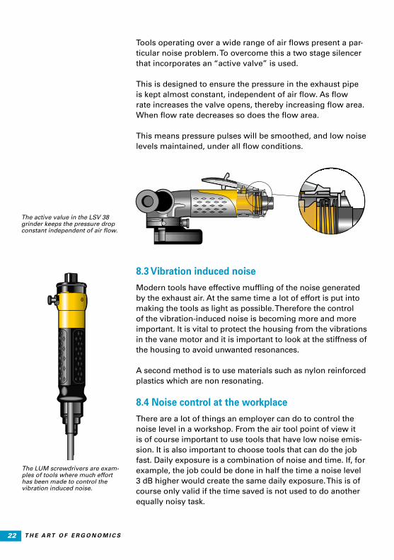
Tools operating over a wide range of air flows present a par-ticular noise problem. To overcome this a two stage silencer that incorporates an “active valve” is used.
This is designed to ensure the pressure in the exhaust pipeis kept almost constant, independent of air flow. As flow rate increases the valve opens, thereby increasing flow area. When flow rate decreases so does the flow area.
This means pressure pulses will be smoothed, and low noiselevels maintained, under all flow conditions.
8.3 Vibration induced noise
Modern tools have effective muffling of the noise generated by the exhaust air. At the same time a lot of effort is put intomaking the tools as light as possible. Therefore the control of the vibration-induced noise is becoming more and more important. It is vital to protect the housing from the vibrations in the vane motor and it is important to look at the stiffness of the housing to avoid unwanted resonances.
A second method is to use materials such as nylon reinforced plastics which are non resonating.
8.4 Noise control at the workplace
There are a lot of things an employer can do to control the noise level in a workshop. From the air tool point of view it is of course important to use tools that have low noise emis-sion. It is also important to choose tools that can do the job fast. Daily exposure is a combination of noise and time. If, for example, the job could be done in half the time a noise level 3 dB higher would create the same daily exposure. This is of course only valid if the time saved is not used to do another equally noisy task.
The LUM screwdrivers are exam-ples of tools where much effort has been made to control the vibration induced noise.
The active value in the LSV 38 grinder keeps the pressure drop constant independent of air flow.

23T H E A R T O F E R G O N O M I C S
9. VIBRATIONS IN HANDHELD TOOLS9.1 What is vibration?
Vibration is a means of describing how a body is accelerated by oscillating external or internal forces. These oscillating forces have different frequencies, depending on their source.
9.2 Why is vibration a concern?
Exposure to excessive levels of vibration can cause vascular injury, damage nerve cells and cause damage to the bones at the joints.
Vascular injury is where the arteries in the fingers thicken, thereby reducing flow area for the blood. The condition is ir-reversible. This injury becomes apparent under coldtemperatures where the body reduces blood supply to the extremities. Because of the restricted flow path the blood can-not pass through the affected areas and sensation is lost. The affected fingers appear white and this phenomenon is calledvibration induced white finger (VWF).
Finger arteries on normal cross section and when affected by VWF.

24 T H E A R T O F E R G O N O M I C S
Nerve cells can be damaged by vibration and this is associ-ated with a loss of sensitivity in the fingers.
In the early stages the damage may be reversible but pro-longed exposure will cause permanent damage. This is the type of induced damage that gives rise to most complaints, because affected persons are restricted in their everyday ac-tivities. Things like buttoning up a shirt, picking up coins from a flat surface or sawing become difficult or impossible tasks.
Bone damage is caused by using tools that require high feed forces. The vibration is passed through the hand and arm causing wear and even fracturing at the joints.
9.3 Measurements to establish vibration emission values
Vibration emission measurements used as the basis for the declared vibration values are made by using the ISO 28927 series of test codes. Corresponding test codes for electric tools can be found in the EN 60745 series. The main purpose of the measurements is to produce repeatable and reproduc-ible values that can be used to compare different tools from a vibration viewpoint. Present standards in the 28927 series use one or two accelerometer positions located between the thumb and the index finger for the hand/hands in contact with the tool. At each point measurements are made in three directions.
A declared value measured using the ISO 28927 series, or the EN 60745 series standards will, in most cases, be repre-sentative of the in-use vibration values which are likely to be experienced in the workplace when the tool is in normal use. According to CEN/TR 15350 a rough assessment can be made using the values obtained using the ISO 28927 series, or the EN 60745 series standards.
9.4 Health and safety regulations
It is very difficult to quantify what exposure time and what amplitude and frequency of vibration causes the injuries described previously.

25T H E A R T O F E R G O N O M I C S
The most indepth analysis of vibration induced injuries has been made by the International Standardization Organisation (ISO) and their recommendations are published in ISO 5349. Many factors affect the risk of developing vibration disorders.Some are highly individual. It is therefore not possible to ex-actly predict the risk on an individual level. Statistically it can be estimated what the probability is that a certain percentage within a group will develop vibration disorders.
9.5 The Physical Agents (Vibration) Directive
In June 2002 the European Union published the Physical Agents (Vibration) Directive (PA(V)D). It outlines new guide-lines for exposure to vibration in the workplace.The Directive has been adopted into national law sinceJuly 6, 2005.
Since that date all member states have had similar require-ments on employers to control vibration exposure for all their operators.
The directive introduces two values. The action value, and the limit value. The values are expressed as 8 hour exposure given in m/s2
When the action value is exceeded, the employer has to start an action program showing a plan for reduction of the expo-sure to below the action value.
It is never allowed to exceed the limit value except in some special circumstances. For more information see Atlas Copco’s pocket guide “Vibration exposure assessment for industrial power tools”. (article No. 9833 1508 01)
Value 8 hour exposure m/s2
Action value 2.5
Limit value 5

26 T H E A R T O F E R G O N O M I C S
10. SOURCES OF VIBRATIONTools for industrial use must be of very robust design to with-stand the hard use they can be exposed to. From a vibration point of view this means that most tools can be regarded as rigid bodies. Oscillating forces act on this body and the result is vibration. The oscillating forces are either independent of the work process or process dependent forces.
The forces independent of the work process originate from, e.g., the imbalance of internal parts in rotating machines or the imbalance of inserted tools. The forces necessary to accel-erate the piston in a percussive tool are also examples of this type of force.
Process dependent forces are generated, for example, whena grinding wheel is in contact with the workpiece or when the shockwave in a chisel to a percussive tool is reflected back into the tool from the workpiece. The contact force between the bolt and the socket when an impact wrench is tighteninga bolt is another example of a process dependent force.
In all cases we are talking about forces as the source of vibra-tion. This leads to the three basic principles to control vibra-tion:
nControl the magnitude of the vibrating forces. Examples are the autobalancer on a grinder or the differential piston in a chipping hammer.
nMake the tool less sensitive to the vibrating forces. Exam-ples can be when the mass of the guard on a grinder is rigidly connected to the tool to increase its inertia.
nIsolate the vibrations in the tool from the grip surfaces. Examples are vibration-dampening handles on grind-ers or pavement breakers and the air-spring behind the blowmechanism in a riveting hammer or the mass spring system in a chipping hammer.

27T H E A R T O F E R G O N O M I C S
11. REDUCING VIBRATION IN HAND-HELD TOOLS11.1 Grinders
As grinders tend to be used over long periods of time it is important to reduce vibrations as much as possible. The greatest source of vibration is the imbalance of the inserted tool (grinding wheel, burr or mounted point). It is therefore important to always use well balanced inserted tools. It is also important that operators are informed not to use a grinder when a newly inserted tool causes excessive vibration. They should immediately scrap the inserted tool involved and use a new one instead.
11.2 Die grinders
Vibrations are caused by out of balance cutting burrs and by the grinding process itself. A method of reducing vibration in the handle is to mount the motor and drive line in a weak suspension, which in this case are rubber elements. The vibra-tions are absorbed in the suspension and are not transmitted to the handle.
11.3 Angle and vertical grinders
Support handles can be used to control vibration in two dif-ferent ways. A rigidly mounted handle will move in phase with the housing. The inertia of the handle will help to reduce the rotation around the main handle.
A softly suspended handle will move out of phase. Its inertia is no longer part of the inertia of the occillating machine. The amplitude of the rotation of the tool around the main handle will increase but only a fraction of the vibration is transmitted to the support handle.
11.4 Turbo grinders
The GTG turbine grinders represent the state of the art in vibration control. The tools are 30 to 50% lower in weight compared to conventional grinders with similar power, and still they have vibrations that are considerably lower than conventional tools. All existing techniques to reduce vibration have been used in the design.
Angle grinder LSV 38 with a sup-port handle with a small extra weight stiffly mounted on the tool to reduce vibrations.
Die grinder LSF with soft suspen-sion of the rotating parts.

28 T H E A R T O F E R G O N O M I C S
The oscillating forces have been reduced by using a spindle with a very stiff bearing configuration in combination with flanges that are machined to tight tolerances. An autobalanc-er is also used. The autobalancer is a device located on the tool spindle that automatically counterbalances any imbal-ance of the wheel.
The tool has been made less sensitive to the oscillating forces by using as much as possible of the available mass in the tool to increase the inertia. On this tool the wheelguard is an important part of the inertia especially for rotation around an axis along the main handle. Therefore the guard is rigidly fixed to the tool using the pressure in the compressed air when the tool is running. When the tool is not triggered there is no pressure and the guard can easily be moved.
The sensitivity to oscillating forces can also be reduced when the distance between the unbalanced forces from the wheel and the center of gravity of the tool is kept as small as pos-sible.
Support handles with vibration isolation were also considered but were rejected due to the fact that vibrations were already low and the decreased maneuverability was regarded as a major disadvantage.
11.5 Percussive tools
With all percussive tools there is a potential vibration source from the movement of the piston and from the changing air pressure that powers it. In a conventional percussive tool this vibration is transferred to the handle.
The GTG turbine grinders are designed using all possible means to reduce vibrations.
Spindle withhigh precision Support handle
Light weight to save 0.4 kg
Shortdistance
Guard locked under grinding
Autobalancer
Use thesleeve
Because the shockwaves in them cause vibration, the chisel or die should never be held.

29T H E A R T O F E R G O N O M I C S
A high level of vibration is generated in the chisel, which is caused when the piston strikes the chisel. This vibration can-not be removed, and for this reason the chisel or die should never be held.
11.6 Chipping hammers
Vibration levels in the handle of a chipping hammer can be reduced by using a “differential piston” percussive mecha-nism. With this design the air pressure acting on the handle remains almost constant and therefore the vibrations in the handle are very small.
11.7 Riveting hammers
For this application very precise control over tool speed and feed force is required. Atlas Copco has developed a success-ful designusing a conventional percussive mechanism, which is isolated from the handle of the tool.
The movement of the percussive mechanism is controlled by an air cushion between the mechanism and the handle. Plac-ing a feed force on the handle of the tool increases pressure in the air cushion, which increases the force on the percus-sive mechanism. In this way precise tool control is main-tained and the vibrations in the percussive mechanism are not transferred to the handle.
11.8 Bucking bars
In a real riveting process vibrations are often higher on the bucking bar side than in the riveting hammer itself. One pos-sibility to reduce vibrations is to use heavy bucking bars. This is often not possible due to weight or space restrictions. Vi-bration controlled bucking bars using the same damping sys-tem as the riveting hammers have therefore been developed. Using a riveting hammer and a bucking bar that are tuned together results in a quick and high quality riveting process.
11.9 Scalers
Scaling does not require a percussive tool. By fixing the chisel to the piston and by allowing the cylinder to move in the opposite direction, the tool can be designed so that the forces caused in the movement of these two masses approxi-mately cancel each other out. Therefore the vibration gener-ated in the handle of the tool is low.
Vibration damped riveting ham-mer RRH with air cushion to re-duce vibration in the handle.
Scaler RVM with two piston system.
Vibration damped bucking bar RBB using the same damping system as the RRH hammers.
Vibration damped chipping hammer RRD with differential piston.

30 T H E A R T O F E R G O N O M I C S
11.10 Impact wrenches and impulse tools
The vibrations in the handle of these tools are generally small, except for the big tools used for very high torque applications. However, incorrect use can cause the operatorto experience high vibration levels.
The main source of vibration is from the socket. To reducevibration the tool and socket should be kept in line, a wornout socket should not be used and the operator should never hold the socket.
The impact mechanism on impact wrenches and the pulse mechanism on pulse tools is a substantial part of the tool weight. It is therefore important to design them so they are very well balanced.
To keep vibration exposure low it is also important to keep the exposure time low. For impact wrenches and pulse tools, choosing a tool of correct size is important. When a tool that is too small for the job is chosen the tightening time rises sharply.
12. LUBRICATION-FREE MOTORSThese allow the working area to be kept free from oil contam-ination. This makes the working environment more pleasant and gives great benefits to operators who have sensitive skin. Lubrication-free motors also give a reduction in maintenance costs and ensure that no oil contamination of the product oc-curs.
Never hold the socket on impact wrenches or impulse tools.

31T H E A R T O F E R G O N O M I C S
13. DUST CONTROL13.1 Why control dust?
The dust from many materials is inert and causes no perma-nent damage. Even so, this dust can make working conditions difficult and unpleasant, which can affect productivity.
The dust from some materials, however, can be harmful and diseases such as cancer, silicosis, asbestosis and toxic poi-soning can result.
The sizes of dust particles that are of most concern are those below 5 microns (5 x 10⁻⁶ metres). Particles of this size can penetrate the body’s defence systems and reach the oxygen transfer areas in the lungs.
13.2 Health
Every country has its own national threshold values of al-lowable dust levels for different materials. These levels are constantly under review. Many new materials are being intro-duced each year and added to the list of threshold values.
13.3 How to control dust
There are a number of methods of ensuring that the operator is not exposed to dust when using hand-held tools. The work bench can have extraction openings connected to a strong vacuum source, a movable extraction hood can be used and the tool itself can be fitted with an extraction system. In ex-treme cases the operator can wear breathing apparatus as an additional protection.
Of the dust collection methods, dust extraction on the tool is the most efficient as collection is at the point of dust creation. This not only ensures very efficient extraction but also allows a relatively low power vacuum source to be used.

32 T H E A R T O F E R G O N O M I C S
14. EXTRACTION SYSTEMSFOR TOOLS14.1 Disc sanders
On all rotating cutting tools heavier particles are propelled at a tangent from the disc. As the particle size reduces, the dust tends to follow the rotation of the disc. It is the smaller parti-cles which are most harmful. To remove the lighter particles efficiently the extraction should be made around as much of the periphery of the disc as possible.
The hood has a plastic or a brush edge to trap heavier parti-cles. There is a cut-out on the front of the hood, which allows sanding into corners and also gives good visibility. This de-sign has improved suction in the area where dust is formed.
14.2 Orbital and random orbital sanders
On orbital and random orbital sanders dust extraction is achieved through holes in the pad. As these tools tend to be used on flat surfaces the dust is kept under the pad.
14.3 Depressed center grinders
The same principle is used for grinding as on the fixed hood for sanders.
14.4 Straight grinders
These are equipped with a shield placed in front of the wheel. This traps the dust, which can then be extracted.
14.5 Die grinders
The burr is enclosed by the hood, apart from a cut-out to give access to the workpiece. This gives dust extraction over the largest possible area.
14.6 Diamond tipped grinders
In this case the dust is extracted through the center of the drum.
14.7 Drills
A flexible hood is used which totally encloses the drill bit during the drilling process. It is designed so the hood can be pulled back to help locate the drill.
Angle sander LSV 38 with dust extraction hood.

33T H E A R T O F E R G O N O M I C S
14.8 Chipping hammers
It is almost impossible to offer a high efficiency extraction system on a chipping hammer. This is because of the difficulty in getting an extraction hood near the point of dust genera-tion. Also because of the different sizes of pieces removed an extraction hood can easily be blocked. The best compromise is to use a flexible rubber hose through which the chisel pro-trudes. This gives the flexibility of positioning the hood in the best position.
Special dust extraction hoods need to be designed for all different types of tool.
Chipping hammer RRD with dust extraction used in building industry.

34 T H E A R T O F E R G O N O M I C S
15. VACUUM SOURCESThere are basically three choices of vacuum source.
nSelf generating vacuum sourcenPortable vacuum sourcenCentral vacuum source
Tools with a self generating vacuum have the lowest set up cost and offer great flexibility. However, the extraction strength is low compared with the other methods. Also when the air supply to the motor is shut off the vacuum in the suc-tion hood and in the collecting bag is lost.
This means the efficiency of extraction is low compared with other methods.
Portable units provide a strong vacuum for 1 or 2 tools. They are ideal for small workshops and for flexible working condi-tions. The initial set-up cost is low, but the units take up work-space and the vacuum unit must be kept close to the tool.
A central vacuum source is used where there are fixed work-stations. This can provide a very strong vacuum and the dust can be easily collected. The system keeps the work area clear. However, the initial set-up cost is high.
Self generating vacuum source.
Portable vacuum source.
Central vacuum system.

35T H E A R T O F E R G O N O M I C S
15.1 Installation of extraction systems
For efficient dust extraction the designed flow rate through the extraction hood must be maintained. For handheld toolsthis is usually between 150 and 250 cubic meters an hour.
When selecting the vacuum source the number of tools thatwill be used, and their required extraction rate, must be known. In addition, the losses in the pipes and hoses mustbe calculated.
Using the diagram below the pressure loss in different lengths and diameters of extraction pipe can be seen.
Graph showing the relation between pressure drop (Dp) and flow for various diameters and lengths of spiral reinforced suction hoses.

36 T H E A R T O F E R G O N O M I C S
For example, assuming a single tool requiring a flow of 200 cubic meters per hour is connected to a vacuum source through a 5 meters, 1 1/2 inch diameter, pipe.
From the graph it can be seen that the pipe will cause a pres-sure drop of 1 800 mm water gauge. In addition, there will be a further pressure drop generated in the extraction hood, couplings, filters, etc. This will be around 500 mm water gauge.
Therefore for this application the vacuum source must main-tain an extraction rate of 200 cubic meters an hour at 2 300 mm water gauge.
It might be necessary to use the same tool and vacuum source but, for example, over a length of 10 meters. In this case, a suitable hose would be one that has a diameter of 2inches, over 7 meters, and a diameter of 1 1/2 inches over3 meters.
To make a tool easy to use the extraction hose should be small and light but unfortunately a small hose causes a large pressure drop. The best solution is to keep the distance be-tween the tool and the main pipework, or portable vacuum unit, as short as possible and to thin the hose near the tool. (This as the reason for calculating the pressure drop over two lengths of pipe in the previous example). It is also important to join the extraction hose and air supply hose together. If this is not done the handling of the tool is made very difficult.
To design a complete centralized system many other factors need to be considered which are outside the scope of this pocket guide. We recommend that you ask for expert advice if a centralized system is required.

37T H E A R T O F E R G O N O M I C S
ATLAS COPCO POCKET GUIDES
Title Ordering No.
Air line distribution 9833 1266 01
Air motors 9833 9067 01
Drilling with handheld machines 9833 8554 01
Grinding 9833 8641 01
Percussive tools 9833 1003 01
Pulse tools 9833 1225 01
Riveting technique 9833 1124 01
Screwdriving 9833 1007 01
Statistical analysis technique 9833 8637 01
The art of ergonomics 9833 8587 01
Tightening technique 9833 8648 01
Vibrations in grinders 9833 9017 01
Vibration exposure assessment for power tools 9833 1508 01
Cable management 9833 1640 01
Testing and calibration in assembly technology 9833 1720 01
Error proofed production 9833 1437 01
LEAN 9853 8215 01
Power Tool Ergonomics (book) 9833 1162 01

38 T H E A R T O F E R G O N O M I C S
NOTES
.......................................................................................................
.......................................................................................................
.......................................................................................................
.......................................................................................................
.......................................................................................................
.......................................................................................................
.......................................................................................................
.......................................................................................................
.......................................................................................................
.......................................................................................................
.......................................................................................................
.......................................................................................................
.......................................................................................................
.......................................................................................................
.......................................................................................................
.......................................................................................................
.......................................................................................................
.......................................................................................................
.......................................................................................................
.......................................................................................................
.......................................................................................................


9833
858
7 01
20
15:1
Jet
lag/
Boa
rdw
alk.
Prin
ted
in S
wed
en.
© A
tlas
Cop
co In
dust
rial T
echn
ique
AB
. All
right
s re
serv
ed. N
o pa
rt of
this
pub
licat
ion
may
be
repr
oduc
ed w
ithou
t the
prio
r per
mis
sion
of t
he c
opyr
ight
hol
der.
COMMITTED TO SUSTAINABLE PRODUCTIVITY
www.atlascopco.com