the and Workshop 19-21, 1988 · NATIONALINSTITUTEOFSTANDARDS& TECHNOLOGY ResearchInformationCenter...
112
United States Department of Commerce National Institute of Standards and Tectinology NIST Special Publication 781 Computerization of Welding Data- Proceedings of the Conference and Workshop October 19-21, 1988 T. A, Siewert, /. E. Jones, and H. G. Ziegenfuss, Editors
Transcript of the and Workshop 19-21, 1988 · NATIONALINSTITUTEOFSTANDARDS& TECHNOLOGY ResearchInformationCenter...

United States Department of CommerceNational Institute of Standards and Tectinology
NIST Special Publication 781
Computerization of Welding Data-Proceedings ofthe Conference and WorkshopOctober 19-21, 1988
T. A, Siewert, /. E. Jones, and H. G. Ziegenfuss, Editors

NATIONAL INSTITUTE OF STANDARDS &TECHNOLOGY
Research Information CenterGaithersburg, MD 20899
DATE DUE
Demco, Inc. 38-293

Odftto
l99o
NIST Special Publication 781
Computerization of Welding Data —Proceedings of the Conference and WorkshopOctober 19-21, 1988
Edited by
T. A. Siewert
National Institute of Standards and Technology
Boulder, Colorado
Sponsored by
National Institute of Standards and Technology
Boulder, Colorado
J. E. Jones
American Welding Institute
Louisville, Tennessee
and
H. G. Ziegenfuss
American Welding Society
Miami, Florida
American Welding Institute
Louisville, Tennessee
and
American Welding Society
Miami, Florida
March 1990
U.S. Department of CommerceRobert A. Mosbacher, Secretary
National Institute of Standards and Technology
John W. Lyons, Director

National Institute of Standards U.S. Government Printing Office
and Technology Washington: 1990
Special Publication 781
Natl. Inst. Stand. Technol.
Spec. Publ. 781
101 pages (Mar. 1990)
CODEN: NSPUE2
For sale by the Superintendent
of DocumentsU.S. Government Printing Office
Washington, DC 20402

ABSTRACT
This publication comprises the proceedings of an October 1988 conference on com-
puterization of welding data. A written summary of each speaker's presentation is included in
its appropriate conference session:
• Overview of computers and databases,
• Welding applications software, and
• Welding case studies.
This publication also includes the proceedings of a workshop which listed future com-
puterization needs in the welding industry and an informal survey of the registrants' usage of
computers on the job, both of which occurred at the conference.
Key words: computerization; database; mechanical properties; procedure qualification
records; welding information; welding procedures
Except where attributed to NIST authors, the content of individual sections of this volume has not been reviewed or
edited by the National Institute of Standards and Technology. NIST therefore accepts no responsibility for com-
ments or recommendations therein. The mention of trade names in this volume is in no sense an endorsement or
recommendation by the National Institute of Standards and Technology.

ABBREVIATIONS
AI artifirial intpllidpnrp
ASME AmpHpan SnpiPtv of A/TppHanipfil T^n(Tinppr<i
ASTM /^iiidi^dXi OUdC^ty L\JL XC/oLlli^ dliVX IVXClL^i idlo
AWT1\. TV i.Am<=*nfan W/i=*lHin(T Tn^titiifpxViiiwi i^dil vv ^iVXlll^ XilotlLLlLW
AWSTV \J Ampripun WplHino" .^opipfv
compuier diueu uesign
CFGR r~V^ntrjil T^lppfripit\; r^pnpratino" RoarH of ^rrp^it T^rit?in^
rr^A
rvNV I Hj^mv \/ notph
DOD i^Cpal LIIICIIL Ui X^ClCIldC
DDF l^Cpal LIIICIIL UI xZ^ilCIgy
DOS HiQlr-onf^rjitino' Q\7Qtf='m
PGA pnhjinppH crr^iT^hiPC JiHjir>for
FCAWX V^ifc. vv fliiY-Porpfl JirpwplHincr
GMAW ^do liiC/Ldl dlw Wi^ivXlil^
HA7 hRat pfff^pff^H TOTIf^li&dL dLLC/WLWlX iCUiiW
ToinincT T'pphnoloCTv Tnformfition r^i=*ntprJVJiliili^ X C^vllilUl^^y XiiLUiliidllUil V^-^ilL^i
MIST MatPriaK Information for Scipnpp and Xpphnolocrv
MPF)IVXX X-/ lYXdiciidio JTiupciLy X^dld
MMA manual mptal arp
NACE National Association of Gorrision Engineers
NASA _ National Aeronautics and Snare Administration
NBS N^ational Riirpan of StanrlarH*^ /^now NTST^lid Liwild! ±J UiWd Li V^L LdiiLidi ViO 1 iiWW 1 1 XO X 1
NIST National Institute of Standards and TechnolopvX ^ KA V AVw/ A XV4 A ^AXU VX V ^X X k.^ ^ LX X X^X t.XX CX A XV* X X X X £L V
NMPDN National Materials Property Data NetworkNNS _ neural netwnrlf svstem
P prouDS classification svstem within ASME B&PV codevXvXtJkJXLXWU t-XV^XX kJJkJ\i\^AXl TTAVXXXXX X J i » m M j .X^V-^X. W
PC personal computer
PEPCO Potomac Electric Power CompanyPQR procedure qualification record
RAM random access memorySAW submerged arc welding
SMAW shielded metal arc welding
TWI The Welding Institute (of Great Britain)
VGA video graphics array
WIC Welding Institute of CanadaWIN™ Welding Information Network*(trade mark)
WPS welding procedure specification
WRC Welding Research Council
iv

CONTENTS
INTRODUCTION 1
SURVEY OF PARTICIPANTS 2
PRECONFERENCE TUTORIAL SESSION 3
CONFERENCE PAPERS -Overview of Computers and Databases 5
Databases for Technology 5
J. Rumble, National Institute of Standards and Technology
Review of the 1 986 Workshop—Computerization of Welding Information 9
T.A. Siewert, National Institute of Standards and Technology
On-line Access to Worldwide Sources of Materials Performance Data 17
J.G. Kaufman, The National Materials Property Data Network
ASM International's Materials Properties Data System: Mat.DB® 26
T.L Gall and W.A. Weida, ASM International
Application of Artificial Intelligence to Welding 31
J.E. Jones, American Welding Institute
CONFERENCE PAPERS-WeldIng Applications Software 39
Computerized Software for Welding Engineers 39
W. Lucas and A.D. Brightmore, The Welding Institute
Computer Applications in Welding 56
B. Chew, Marchwood Engineering Laboratory
CONFERENCE PAPERS-Welding Case Studies 61
Update on Procedure Qualification Records and Welding Procedure Specifications 61
H.G. Ziegenfuss, American Welding Society
Computers in Welding--from Breadboards to Desktops 62
F.R. Baysinger, R.A. Hansen Company
Weld Improvement Program: Weld and Welder Tracking System 68
W. Newcomb, Potomac Electric Power Company
Expert Systems for Diagnosing Problems In Welding Power Sources 79
T. Flynn, Miller Electric Manufacturing Company
WORKSHOP SUMMARY 83
Appendix A. List of Participants 91
Appendix B. Survey Form 97
Appendix C. Responses to the Survey 99


Introduction
INTRODUCTION
The first workshop on computerization of welding data was held in 1986. It produced a
list of national welding data needs to guide software developers and other computer profes-
sionals.^ Since then, substantial improvements have occurred in software, hardware, and the
acceptance of database technology. In the spring of 1988, the National Institute of Standards
and Technology, the American Welding Institute, and the American Welding Society decided
to plan another workshop to assess the progress. After further discussion, they decided to or-
ganize (1) a conference to present the latest developments, (2) a subsequent workshop to
produce a new list of needs, and (3) a preconference tutorial to give novices a background on
common computer applications, such as word processing and database management.
The conference, workshop, and tutorial were held October 19 through 21, 1988, in
New Orleans, Louisiana. Sixty-one managers, welding engineers, and computer professionals
attended. The list of participants is included in AppendixA This report is a chronological
record of the conference and workshop.
^ Computerization of Welding Information—A Workshop Report, T.A. Siewert and J.E. Jones, eds., National Bureau
of Standards (U.S.) Special Publication 742, National Bureau of Standards, Boulder, Colorado, 1988.

Computerization of Welding Data
SURVEY OF PARTICIPANTS
To provide additional information for the conference planners, all registrants were asked
to complete a survey form (Appendix B). Those whose forms had not been received by the
start of the conference were asked to complete a form at the beginning of the conference.
The survey was designed by the conference committee to determine the size of the room,
the number of computers needed for the preconference tutorial, and which welding industry
groups would be represented at the workshop. The tabulated data are included in this report
(Appendix C) because they provide a measure of the use of computers in the welding industry
and perceived needs for the future.
Results of the survey were surprising. The organizers expected that only a small numberof the participants would feel the need for the tutorial in basic computer capabilities. Aboutninety percent of the participants were interested in attending the tutorial, even though their
survey replies indicated considerable knowledge of computer capabilities. The obvious con-
clusion was that, in spite of their experience, they wanted to take advantage of this oppor-
tunity to review their skills and possibly learn about recent advances.
Most of those surveyed have access to personal computers, from 8088 chip-based ma-
chines to 80386 chip-based machines and work stations. Although participants at the 1986
workshop were not polled, it seemed that less than half had access to a personal computer.
This tremendous increase in computer availability indicates an influx of computers into the
welding industry (and so the value of this conference). Since the participants had both welding
and computer experience, they were well-qualified to produce a list of national welding-data
needs.
The survey also asked the participants to list three industry groups that would describe
their interests. The objectives were to characterize the types of industries that were repre-
sented at the conference and to select topics for the group discussions in the workshop. Thechoices (see Appendix B) included the top ten topics identified at the 1986 workshop and an
optional write-in topic. Three of the top four choices of the 1986 workshop were listed at the
top again (see Appendix C), indicating that these areas of the welding industry have data
needs that can be met by databases, and the needs are sufficient to send someone to a con-
ference. Although several new topics received some votes, the top ten topics remained virtual-
ly the same.
2

Introduction
PRECONFERENCE TUTORIAL SESSION
The preconference Tutorial on Computer Applications was held on October 19, 1988,
just before the workshop began. Attendance was excellent—most of the conference partici-
pants attended. The tutorial, which was prepared by P. Oberly and M. D'Attilio of the
American Welding Institute, consisted of four sections describing the personal computer's role
in welding engineering:
• Report writing with a word processor software program
• Designing with a computer-aided design software program
• Cost calculation with a spreadsheet software program
• Welding procedure generation with a database software program
Computers (IBM compatible) were available for participants to use during the presenta-
tions and to gain first-hand experience with popular personal computer software. WordStar,
AutoCAD, Lotus 1-2-3, and Dbase Ill-f were used to illustrate the four topics presented.
The sessions apparently gave the participants new ideas and techniques for using the personal
computer to help them in welding engineering.
3

Conference Papers—Overview of Computers and Databases
CONFERENCE PAPERS -Overview of Computers and Databases
Databases for Technology
J. Rumble
National Institute of Standards and Technology, Gaithersburg, Maryland
Introduction
Databases are growing in popularity because they have many advantages over other
sources of data. They are extremely comprehensive. A read-only compact disk (CD-ROM)contains the equivalent of many pages of text. On-line systems have sizes in the gigabyte
(10^-byte) range.
Databases can be easier to use, faster, and more convenient than other sources of infor-
mation. With powerful search procedures, they enable one to search many data fields (effec-
tively functioning as the ultimate index). This rapid access to many sources of information
substantially increases efficiency.
Databases facilitate manipulation of the data by rearranging the data into subsets or
supersets and changing dimensions and units. Programs can be linked so that specific tasks can
be performed within the database or a subset of data can be sent to other software for further
processing.
The flexibility of a database enables the data to be compared or contrasted in virtually un-
limited ways. A very effective way to evaluate comparisons is on the screen, before deciding
whether to save the information or to produce a printed copy. Data can be displayed in a wide
variety of graphic formats or tables. Desktop publishing programs combine the text, tabular
data, and graphic data into a report having the same quality as one that has been typeset.
General Progress in Database Development
A major trend in databases is the growth of those that reside in small personal computers.
A 1985 NBS (now NIST) survey revealed only one materials database of this type; a 1988 sur-
vey revealed dozens, with many more to be released soon.
Personal databases have some advantages over databases on large, centrally based com-
puter systems: Personal-computer-based systems are available on demand. The user is not sub-
ject to the slowing of response that occurs on large systems when another user submits a large
job. A PC system is also available during the evening and weekends, when a central system is
often committed to batch accounting jobs or scheduled maintenance.
5

Computerization of Welding Data
The software for the PC has been developed for a large market of users, justifying a well-
designed users' manual, often with a toll-free number to a software engineer. Good support
gives users confidence and promotes the use of personal systems over central systems. The per-
sonal nature of small computer systems encourages the user to customize it for his individual
needs.
Progress has also occurred in the area of interfaces. Color screens enable more striking
displays of the data, calling the viewer's attention to selected fields or trends. The designer can
include more data on the screen without confusing the viewer. Taking full advantage of the
newer color monitors are enhanced-resolution graphics packages. They enable data to be rep-
resented on the screen as pictures or detailed schematics, two forms that are particularly ap-
propriate for design work or complex configurations. Improvements in interfaces also include
better screen designs, clearer menus, and self-teaching capabilities.
The variety of data now available in databases is increasing. New databases are being
developed for material properties that have not been available before in any format. Existing
databases are being updated to include new materials and more complex information on ex-
isting materials. For example, the NIST Crystallographic Database expanded from 40,000
compounds in 1985 to 137,000 in 1988. This depth and breadth of data are needed if these
databases will be evaluated by statistical techniques for process control and design applications.
Progress is also occurring in the development and application of expert systems. This
technology promises substantial increases in searching efficiently; it guides the user through
a series of customized decision trees rather than through general menus. Expert systems can
also help with interpretation of data by developing recommendations from incomplete data,
estimating the validity of data, or evaluating conflicting data.
Technical Database Developers
Groups that are developing databases are generally those who have disseminated data in
handbook form, those who see this as another way to support a project (for example, a
manufactured product), and entrepreneurs responding to this new market. For example, tech-
nical societies have traditionally produced handbook data, but they project a loss in revenue if
their data are not also available in a database format. Publishing houses perceive it in muchthe same way, except that the dissemination of information for profit is their main business,
rather than an ancillary activity, as it is for technical societies. Databases are another way to
distribute the data that government and independent research groups generate. Some govern-
ment agencies have been assigned the task of giving guidance to database development by
working with private organizations to produce standards. Semiprivate agencies and
entrepreneurs see the growth in the demand for data as an economic opportunity. The sales
and marketing departments in manufacturing firms find that databases can support their
products in the field and expand their market.
6

Conference Papers—Overview of Computers and Databases
Trends in Materials Databases
Current trends include the networking of individual databases into large sources of data,
development of new and expanded databases, and the development of data standards. Ex-
amples of the networks and new databases are
• MPD Network by National Material Property Data Network
• European Materials Information Services Network bythe Commission of the European Communities
• MetSel2 and EnPlot database and software by ASM International
• Cor Sur2 database by NACE and NIST
• Software System for Plastic Material Data by International Plastic Selector/IDES
• Low-Cycle Fatigue Material Test Programs by MTS
• Weldselector by the American Welding Institute
• Computerized Alloy Steel Information System by Minitech
• Expert Systems for Hazardous Chemicals by MTI, NDI, and
the NACE-NIST Corrosion Data Center
In the area of standards, ASTM Committee E49 is developing standards for material
descriptions, reports of test results, data exchange, and data-quality indicators. A task group
is devoted to the special needs of the welding industry.
Technical Database Development Needs
A major problem that has developed is compatibility among sources. Complex problems
require data from many sources, data which must be combined and processed. Even if the data
from each source could be processed separately, the users would not want to learn a large
number of commands for each system. It is not certain that standards to produce data-system
compatibility will succeed. A related problem is duplication of data in different databases. Will
these data be recognized as duplicates or will they receive undue weight during statistical
analysis?
Another problem is the substantial investment necessary to construct the database and
enter the data, and during the construction phase there is very little income. Before the invest-
ment is committed to a database, a clear understanding of the estimated life and income from
the data must be developed, so that a current net value can be calculated and compared with
the construction cost.
Gaps in the data must be eliminated. Since databases are relatively recent, many are still
incomplete. Data entry must not only keep up with the receipt of new data, but must also be
able to fill existing gaps in the data. Some databases may have a bias, such as those including
only the products of a single producer, and the user must be aware of the bias when interpret-
ing the data.
7

Computerization of Welding Data
Quality of the data must be evaluated. Unless some review is made of incoming data, it is
possible to put inaccurate data into the system. Even data within the system must be evaluated
periodically to ensure that they are not outmoded or obsolete. Simply stating that the data
must be of a certain quality may be insufficient, because there are no agreed-upon levels that
are used for evaluation.
Lack of awareness will be a continuing problem as long as this field develops rapidly.
Few know all the databases that have been developed. Perhaps an on-line catalog is a solution.
Conferences, such as this one, help. It is also difficult to keep up-to-date with the many items
of hardware. As new and improved database software is developed, better interfaces will be-
come possible. Simpler and more logical interfaces will generate a larger market.
The Future of Technical Databases
These problems and needs are topics for research by database developers. As they de-
velop solutions to these problems, we anticipate substantial growth in the uses and benefits of
databases. Compatibility will increase through networking and the development of stan-
dards. The uniformity of the data will increase as groups with vested interests or mandated
responsibility continue to strive toward this goal. The databases will become more complete
as data-entry efforts continue. The quality of the data and the interfaces will increase as the
developers respond to user comments and look for additional sales. The awareness of the
databases will increase as the developers learn better ways to market the system. Interpreta-
tion of the data will improve through the use of expert systems.
Summary
The future for the database looks very bright. The problems that I have mentioned are
the normal result of growth in a new technology; they will guide the developers. The search
for solutions to these problems should result in a new generation of improved databases.
8

Conference Papers—Overview of Computers and Databases
Review of the 1 986 Workshop-Computerization of Welding information
T.A. Siewert
Fracture and Deformation Division, National Institute of Standards and Technology,
Boulder, Colorado
Introduction
The United States is recognized as a leader in the development and application of com-puter systems, from mainframes to microcomputers. Recently, smaller, yet more powerful,
computers have become affordable even to small companies. It is quite logical to apply this
technology to the welding industry, especially since its recent slow growth has stimulated a
search for ways to increase productivity.
A workshop on Computerization of Welding Data, cosponsored by the National Bureauof Standards (now National Institute of Standards and Technology) and the American Weld-
ing Institute, was held in 1986 to determine what data the industry needs, if the data exist, and
whether the development of national welding databases could increase productivity.
The workshop was organized into two sessions: one to define and rank the data needs of
the welding industry and the other to determine desirable characteristics of possible welding
databases. Within each of these sessions, invited speakers shared their experiences; then small
groups discussed the topic. At the close of each session, all participants discussed the recom-
mendations of the small groups and reached consensus. This report summarizes the detailed
workshop report.'^
Workshop Summary
For convenience, the workshop is summarized under two general concerns, ranking of
welding data needs and definition of the needs.
Ranking ofWelding Data Needs
The keynote address by F.J. Smith emphasized recent advances and trends in computers
and data management systems.
• Most databases have been developed for business or financial applications. Only
recently have they been developed for engineering and scientific applications.
• Databases should emulate books to facilitate our use. Retrieval must be sure, con-
venient, fast, and economical.
• The best systems are on-line; they are limited by media storage capacity. Increases
in processor speed and increased memory will enable microcomputers to replace
on-line computers in large-scale database applications by the early 1990s.
9

Computerization of Welding Data
Four speakers from different disciplines within the welding industry gave their perspec-
tives of database opportunities. H.B. Cary described the rapid trend toward automation in
welding and explained how this created demands for information and information processing.
G.R. Olejniczak described how the National Training Fund developed a database of personnel
qualification records (PQRs) for more efficient matching of qualified welders with jobs. F.C.
Breismeister described the extensive data requirements of a large prime contractor or design
firm and emphasized that engineering judgment must be used to assess the accuracy of data.
J.G. Kaufman described the value of a gateway system to link a variety of different databases
and provide supporting information, such as nomenclature or graphics.
The participants developed and ranked a list of topics that described the various interests
of the welding industry. The top four topics (thick-section welding, electrodes and welding
machines, ferrous-metal welding, and pressure-vessel welding) were chosen as subjects for
small group discussions. Participants were asked to identify the welding data needs within their
topic area by using some of the ideas suggested by the speakers. When the small groups re-
turned, the lists of data needs reported by each of these groups were added to a master list.
The entire workshop then ranked these data needs in descending order of importance for the
welding industry. The top four needs were
1. General welding procedures
2. Properties of materials
3. Procedure qualification records (PQRs)
4. Welding variables
Definition of the Needs
J.E. Jones described the differences between traditional data (numerical information,
character information, and text) and nontraditional data (graphics, images, recorded speech,
annotated speech, motion images, and knowledge information) that can be stored in advanced
computer systems. J. Rumble outlined the importance of careful planning, design, selection of
hardware and software, and implementation to achieve a successful database. He stressed the
importance of database design based on user needs, common sense, modern software, and a
realistic schedule.
The participants were divided into four groups again, one for each of the top four data
needs. Using the guidance given by the previous speakers, they were to characterize the data
needs by developing a list of potential users, content, sources of information, and other key
concerns.
10

Conference Papers—Overview of Computers and Databases
Group 1—General Welding Procedures
Potential Users
The group identified the potential users of the welding-procedures database:
Primary Users
Welding engineers
Welding foremen or supervisors
Welders and welding technicians
Quality-assurance engineers
Quality-control engineers
Other Users
Engineers in manufacturing
Draftsmen
Design engineers
Welding distributors
Customers and buyers
Manufacturers of filler metal and equipment(such as power sources)
Content
In addressing the amount of data that is required for a reliable data source, the groupdiscussed
• the number of welding procedure specifications (WPSs) that are needed to cover a
specific area
• the quantity and degree of coverage that would represent a database sufficient to
provide 90% of the required data in the area of sheet-metal work, ASME codewelding, pipe welding, and structural welding.
The consensus of the group was
Number ofWPSs Required
15
50
150
about 100 to 150
Area
sheet-metal work
ASME-code welding
pipe welding
structural welding
Sources ofInformation
The primary source of welding procedures information is probably government labora-
tories, followed by military contractors. Other sources are public and governmental utilities,
the Electric Power Research Institute and government contractors, such as contractors for
the Bureau of Reclamation and the Army Corps of Engineers. Technical societies and associa-
tions could also contribute to the system. Through their research, universities, electrode
manufacturers, and technical welding institutes throughout the world also develop welding
information. Finally, the welding industry would be another valid source of information,
provided that a nontraceability function could be incorporated into the database (see next
section). An especially important consideration is the validity of the data from these sources.

Computerization of Welding Data
Liability Considerations
The subject of data sources included a discussion of strategies for convincing companies
to release information for the system. The problem is to obtain WPSs and PQRs from the in-
dustry in such a way that the liability of using them does not extend to those who supplied
them. Suggested solutions to this problem included disclaimers, limitation-of-liability laws
(which could be in the form of laws or guidelines from Congress), anonymity of sources,
Department of Commerce guidelines, tax breaks, technical-society administration, studies
to defend the competition, and promotion of the system by the government.
Group 2—Material Properties
Potential Users
Potential users consist of
• welding engineers
• design, product, and other engineers
• other technical people
Content
The users of a welding-oriented properties database would be particularly interested in
two types of data:
• data that are specific to welding and generally not available from other sources
• data aimed at other applications but useful in welding applications (data needed
mainly for completeness of the database)
The following five categories of welding data have significant areas of missing information:
• weldment versus all-weld-metal properties
• fracture and impact toughness ofHAZ• test detail (precise location ofHAZ in CVN specimens)
• material history (temper embrittlement)
• welding history and filler-metal traceability
The specific size of the database that is needed to provide an adequate data source was
not addressed. Instead, the group felt that the size of the database should be sufficient to pro-
vide state-of-the-art data coverage for materials as well as materials-testing data.
Sources ofInformation
The group listed the following sources of data:
• welding institutes (AWI, EWI, TWI, WIC, . . .)
• Materials Property Data Network
• manufacturers
12

Conference Papers—Overview of Computers and Databases
• literature
• failure-analysis groups
• producers of materials
• universities
• research laboratories
• utilities
• users
• government
• code bodies
• consultants
Group 3—Procedure Qualiflcation Records
Potential Users
The group felt that large fabricators have databases of procedures that are sufficient to
cover most of their current needs. However, as the use of materials changes, and as greater
code acceptance of the standard PQRs in the database increases, even the large fabricators
will find a PQR database useful. Initial users are expected to be
• contractors (small and large)
• fabricators (small)
• welding engineers
• industries with existing databases (to fill gaps in their data)
• consultants
• inspection laboratories and agencies
• universities (limited)
Content
The database content should include the information on the Welding Research Council's
(WRC) Welding Procedures Committee forms. Specifically, testing data should be included
with the PQRs. An acceptance consensus must be established for PQRs on three issues: stan-
dardization ofPQR information, codified acceptance of these standard PQRs, and standard
forms for PQRs. State and federal regulations (including military standards) should also be
incorporated into the PQR database standard.
The group was concerned with "gaps" or "holes" in the data. The database administration
should interact with industry and government to obtain data that could be used to fill the gaps.
The database should be designed in a modular format so the gaps can be filled easily. Gaps in
existing data that must be filled are
13

Computerization of Welding Data
• effect of joint misalignment and overlaps
• PQRs for materials thinner than 5 mm (0,2 in)
• PQRs for exotic materials
Although generation of the database will be a massive task that will be more difficult as its
size increases, a large database is needed to provide a size that forms a "critical nucleus" for
the user. The PQRs entered should cover a very broad scope and include as many codes as
possible. If possible, the initial database should include 10,000 to 20,000 PQRs.
Sources ofInformation
Principal data contributors were identified:
• Welding Procedures Committee of the WRC (including code acceptance)
• industry
• national laboratories (DOD, NASA, DOE, and their contractors)
• bureaus and associations (e.g.. National Construction Association,
National Certified Pipe Welding Bureau)
• state agencies
Group 4—^Welding Variables
Potential Users
The potential users of a welding variables database are diverse:
• welding engineers
• designers
• quality-control and quality-assurance engineers
• researchers
• process engineers
• managers
• design engineers
• regulating bodies
Content
The group decided that the appropriate scope was "all the data needed for a good weld."
Although some disagreement existed with respect to the amount of data coverage represented
by that expression, it was felt that providing too much data was better than supplying too little.
It was estimated that the minimum size for an effective database was 5,000 data records.
14

Conference Papers—Overview of Computers and Databases
This discussion group approached the issue of gaps in the data in terms of their causes
rather than their types. They determined the causes to be
• validation
• lack of access to proprietary data
• incompleteness of records
Sources ofInformation
Data sources identified for welding variables were also diverse
• cooperative-research societies (especially for PQR data)
• published literature (domestic and foreign)
• manufacturers' literature
• government (domestic and foreign)
• internal documentation from users and suppliers
• patents
• university research
Case Histories
To facilitate the participants' review of these lists of users, content, and sources, four
speakers reported their experiences with database development. J.E. Sims related the develop-
ment and evolution of a 10,000-record WPS database. G.R. Olejniczak described a national
database on sheet-metal welders personnel information and qualification histories.
J.E. Jones talked about a welding information network that includes weld- and base-
metal composition and properties, welder qualification histories, weld-procedure information,
design information (weld symbols and design graphics), and corrosion and wear information.
A. Kuhne described an expert system designed to enable welders to diagnose and correct weld
defects.
Final Discussion
On the basis of these case histories, the participants refined the characteristics of welding
data needs to include safety information and wind-velocity effects. The participants also listed
the ways in which the data should be disseminated: tapes or diskettes, computer phone lines,
phone lines with trained operators at computer terminals, and the mail.
Summary
The previous workshop on Computerization of Welding Information, sponsored by the
National Institute of Standards and Technology (at the time of the workshop, the National
Bureau of Standards) and the American Welding Institute, was held August 5-6, 1986. Its goal
was to determine whether national welding productivity could be improved through the
development of welding databases.
15

Computerization of Weiding Data
The topics of the workshop were introduced by specialists in those areas. The 42 welding
engineers, welding managers, and computer scientists who attended discussed these topics in
small groups. These groups identified the most useful topics for welding databases, in descend-
ing order of importance, to be
1. General welding procedures
2. Properties of the weld, heat-affected zone, and base metals
3. Procedure qualification records
4. Welding variables
For each of these topics, the participants identified potential users, content, and sources
of information. They concluded:
1. A significant portion of the data needs can be met by existing information, but this
information should be carefully screened and reviewed before inclusion in databases.
2. Databases should be accessible to the greatest number of potential users.
3. Databases should use the latest computer technology and be upgradable to newtechnology as it becomes available.
References
1. Industry StatisticsAnnual Survey ofManufacturers 1981 to 1986, United States Bureau of Census,
Washington, D.C.
2. Computerization of Welding Information—A Workshop Report, T.A. Siewert and J.E. Jones, eds., National Bureau
of Standards (U.S.) Special Publication 742, National Bureau of Standards, Gaithersburg, Maryland, 1988.
16

Conference Papers—Overview of Computers and Databases
On-line Access to Worldwide Sourcesof Materials Performance Data
J. G. Kaufman
The National Materials Property Data Network, Columbus, Ohio
Introduction
A broad, cooperative approach to establish easy access to high-quality materials-property
data was the recommendation of the 1982 Fairfield Glad Conference,^ sponsored by CO-DATA, the National Institute of Standards and Technology (NIST; formerly the National
Bureau of Standards), and the Materials Properties Council (MPC; formerly the Metals
Properties Council). Independently, a study of the National Materials Advisory Board arrived
at the same conclusion.^ Subsequently, a number of groups initiated action toward achieving
this goal,'^^ and in 1984, the National Materials Property Data (MPD) Network was formed.^
The MPD Network works with technical societies, government laboratories, universities,
and more than fifty private industries in the quest for better access to quality data from world-
wide sources. This is being accomplished with an on-line network of well-documented data-
bases, each focused on a specific area and managed by experts in that area, and a simple
interface that is accessible to the occasional user. The MPD Network does not duplicate other
services; it provides users with information on all data sources. The work of the MPD Network
includes publicizing and distributing data to material experts, to aid them in design and mate-
rials selection.
In this paper are given an overview of the plans and implementation of the MPD Net-
work's pilot and production systems. The plans for databases for welded, adhesive-bonded,
riveted, and bolted joints are described.
Implementation of the MPD Network
The implementation program for the MPD Network includes two major elements:
(1) the research prototype network that is based on SPIRES and the technology developed
by the NBS-DOE-MPDN project, which is known as Materials Information for Science and
Technology (MIST) and (2) the production MPD Network based upon MESSENGER on
STN International.
The Pilot MPD Network
The development of a prototype network of materials databases began early in 1986,
when the MPD Network and Stanford University joined the MIST project initiated by NISTand DOE. The Pilot MPD Network project, built upon the MIST architecture developed
primarily by J.L. McCarthy of Lawrence Berkeley Laboratory (LBL),^ added a new user-
interface concept and new databases.
17

Computerization of Welding Data
The pilot system utilizes the SPIRES database management system augmented first by
McCarthy (version MPDNl) and later by the Stanford University Commercial Information
Resources Group under S.B. Parker (version MPDN2). Written in Fortran 4, it runs on an
IBM 3091 at Stanford; it can be accessed from anywhere in the world via the GTE Telenet,
a telecommunication service connected to local telephone systems.
The MPDNl version of the MPD Network contained three databases: (1) significant
portions of MIL-HDBK-5, an aerospace industry design handbook, (2) a few sections of the
Aerospace Structural Metals Handbook (ASMH), evaluated data summaries from the litera-
ture, and (3) STEELTUF, a database of approximately 20,000 test results for more than 50
steels. These databases were chosen because they represented different types of data, from
single-value design properties to large groups of replicated "raw" data, thus providing a chal-
lenge in storage and retrieval.
The MPDN2 version added a fourth database, MARTUF, which was developed jointly by
the U.S. Coast Guard, the Ship Structures Committee, and the MPD Network. This database
is a compilation of test data on the toughness of steels for marine applications; it includes one
of the most completely documented data sources available, especially for weld properties.
The Pilot MPD Network is available on-line to its financial sponsors (about thirty-eight
accounts are active). Principally, it is a research tool for developing, evaluating, and refining
search strategies and the user-interface system. It is also valuable for gaining experience with
an interactive metadata system. Users of the pilot system find the interface easy to use and
appreciate the many search options and the metadata system. The pilot system will remain on-
line at least until the production version is available.
The Production MPD Network on STN International
STN International is the premier on-line scientific and technical information database net-
work. It is operated by the American Chemical Society's Chemical Abstracts Service (CAS) in
Columbus, Ohio; FI2^-Karlsruhe, a scientific and educational organization in Karlsruhe,
Federal Republic of Germany; and the Japan Information Center of Science and Technology
(JICST) in Tokyo, Japan. Through an agreement with the American Chemical Society, the
MPD Network services will be offered on STN International, with 1990 the targeted start date.
Production enhancements to the underlying MESSENGER software and the design and
loading of a number of files are under way and will continue at an aggressive pace. Although
new capabilities are being added, all the features of the pilot-system interface will be retained.
Numerical information that will be available includes the mechanical and physical properties
and other performance data for all structural materials, related substances, and associated con-
nection and joint materials. The latter encompasses the documentation needed for proper
characterization of adhesive-bonded, bolted, riveted, and primarily, welded joints.
18

Conference Papers—Overview of Computers and Databases
Key Features of an Integrated On-line System
Among the many issues to be addressed in implementing an international network of
databases are (a) an easy-to-use interface, (b) a variety of search options, (c) presentation for-
mats that provide sufficient documentation, (d) distributed sources, (e) associated analytical
and graphics capabilities, and (f) downloading to and integration with PC systems.
User Interface
Users of the MPD Network -will include not only professional searchers trained in the use
of on-line command-driven systems, but also a new, diverse group of end-users. Searches for
numeric or factual data are often so specific that relying upon intermediate searchers, how-
ever knowledgeable, may require many iterations and still not be satisfactory. Enabling the
search to be performed by the user of the information improves its efficiency.
These end-users will include engineers and scientists from small and large companies and
even consultants, who will use the MPD Network occasionally. They do not have time to read
ponderous manuals, learn complex command languages, deal with cryptic response messages,
and relearn the system operation every time they use it. Thus, a logical, easy-to-use interface is
essential for these users.
Responding to these needs, the MPD Network will provide
a. very logical, menu-driven search paths
b. a variety of search paths for the different queries required by different users
and different applications
c. a "metadata" system in the form of an interactive thesaurus, which translates
user queries to nomenclature and terminology acceptable to the system and
quickly clarifies the meaning of names, terms, and abbreviations
d. a directory of data sources, including those outside the MPD Network
Search Options
Depending on the nature of a query, the program will request different kinds of
information:
a. a database with specific data, e.g., design values
b. a specific material for which different types of data are sought
c. comparison of one or more properties of different materials, perhaps within a
specified range of values
An "expert" mode of searching will be an option for experienced users who do not need
the depth of guidance provided by menu-driven screens. This mode will circumvent the many
menus and enable the researcher to go directly to the information needed.
Those acquainted with the STN International command language will have the option of
searching in the familiar STN mode.
19

Computerization of Welding Data
Presentation Formats
The type of user and the type of queries must also be considered in establishing options
for presentation formats. Adequate documentation is needed to define properly the source
and applicability of data presented on the screen. This may go well beyond the user's request.
However, basic facts, such as the type of data (design value or individual test result) and the
applicable orientation (longitudinal or short transverse), should never be in doubt.
For the MPD Network, key information will be automatically displayed for each query.
Even the brief displays to assist users in narrowing their query will contain certain basic facts,
such as the type of data and key variables.
Distributed Sources
A key element of a true network of interactive databases is the ability to provide access to
databases in various locations without interfering with the efficiency and ease of the search.
Ideally, the network would have nodes in many locations and be able to work with many data-
base management systems and languages. Realistically, those requirements impose a level of
complexity for which we are not yet prepared.
The MPD Network designers plan to take full advantage of the three nodes or service
centers on STN International and work toward linking European and Japanese databases on
materials with those in the United States. Then materials databases loaded by JICST in Tokyoand FIZ-K in Karlsruhe would be available to users of the MPD Network. Such databases will
be loaded in STN files accessible via MESSENGER software. Databases not loaded at one of
the STN service centers would not be accessible through the MPD Network, although infor-
mation on their availability would be provided.
Capabilities for Analysis and Graphics
Capabilities for analysis and graphics is a far-reaching subject, too broad for the scope
of this paper, but a basic approach can be described. Consistent with the capabilities being
developed within STN International, increasing levels of on-line analytical treatment of data
will be provided. However, analysis and graphing of data are usually more efficient and eco-
nomical when done on the users' computer systems rather than on-line.
In certain instances, software products such as STN EXPRESS will be adapted to provide
these functions, and downloading capabilities will be provided to enhance the users' ability to
interface with their own software.
Performance Data for Welded Joints
The scope of the MPD Network databases includes not only the properties of metals,
polymers, ceramics, and composites, but also those of all kinds of joints and connections as-
sociated with these materials, including welded joints. We are making every effort to include
existing databases, such as that for welds in aluminum alloys from Iowa State University^ and
the Fatigue Database from The Welding Institute.^ At minimum, we will provide reliable infor-
mation on how to access them.
20

Conference Papers—Overview of Computers and Databases
We are also working with groups such as the Materials Properties Council ( Martin
Prager, Executive Director) and the Ship Structures Committee to build new databases that
fill voids in data needs. Such a database, MARTUF, is discussed in more detail below.
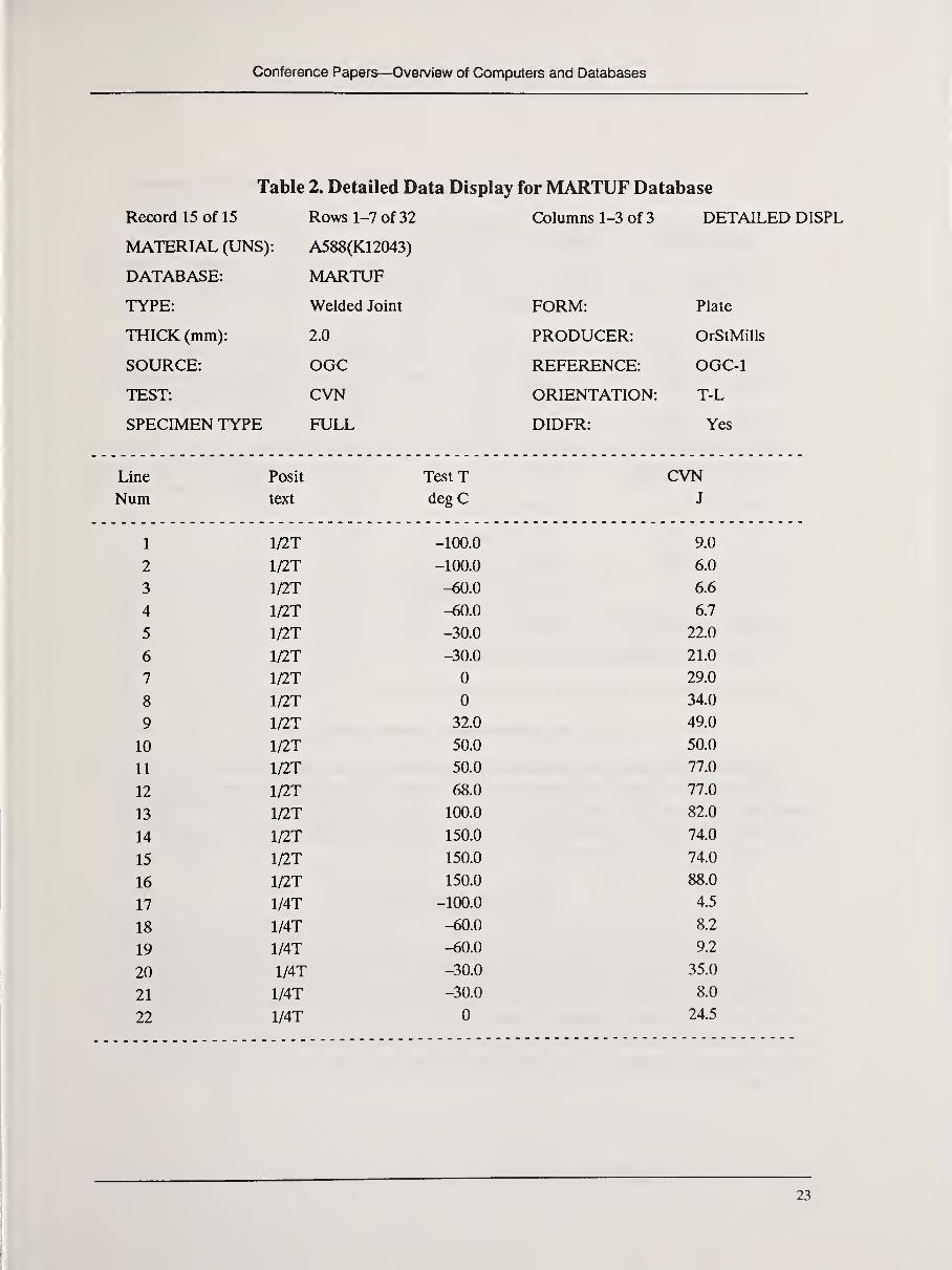
The MARTUF Database
MARTUF is a database of the toughness of steels for marine-industry applications.^^ It
contains about 10,000 individual test results for about 15 steels specifically identified by the
U.S. Coast Guard and the Ship Structures Committee as candidates for ship and marine struc-
ture applications. Data from many types of toughness tests are included, such as Charpy
notched-bar impact, plane-strain fracture toughness, nil-ductility, drop-weight tear, and dyna-
mic tear. MARTUF is being added to the Pilot MPD Network and will be included in the ini-
tial production version.
Data fields that are descriptive of the weld process and conditions are summarized in
Table 1. The level of detail was prescribed by Dr. Prager as a result of his studies of the data to
be included in the database and an assessment of the parameters that are important for deter-
mining levels of performance or for making comparisons with other data sets.
The basic type of weld process, the preweld treatment of base materials, and the postweld
treatment of joints are, of course, of primary importance. Equally important is careful iden-
tification of the location of the test portion of the specimen with regard to the weld metal and
adjacent heat-affected zone. The composition of the weld metal will also be included whenknown.
Those who have searched for data on welded structures know that seldom is all the infor-
mation given in Table 1 available. In far too many cases, some of this information was never
recorded. Nevertheless, the format was designed to store these details when they are available,
in the event it is needed by someone.
This format will not unduly submerge researchers in too many details because retrieval
can be restricted in two ways:
1. The original presentation of the data is structured to show only the general
descriptors of material needed by most users (Table 2); additional information can
be requested. For example, "?WELD" leads to a tabulation such as that in Table 3.
This is the procedure used in the MARTUF database on the Pilot MPD Network.
2. The format of the data can be set by identifying the desired parameters and their order
of presentation. This approach provides the greatest flexibility; it will be used in the
production version of the MPD Network.
21

Computerization of Welding Data
Table 1. Weld Descriptor Information in MARTUF Database on MPD Network
W-1 WCODE Weld code Alphanumeric identifier
W-2 WELD Weld type SAW-submerged arc weld,
SMA-shielded metal arc,
GTA-gas tungsten arc, . .
.
W-3 BTHIK Base metal thickness (mm or in)
W-4 PHTMP Preheat temperature (°Cor °F)
W-6 JPREP Joint preparation V-vee groove; U-U groove.
SB-square butt, . .
.
W-7 GAP Base metal gap (mm or in)
W-8 INTPT Interpass temperature (°C or °F)
W-9 PASES Number of passes numbers 1 to 1000
W-10 HLLR Filler metal specification alphanumeric
W-11 HLNM Filler metal trade name alphanumeric
W-12 HLRC Filler metal carbon (%)content
W-13 FILSZ Filler metal size (mm or in)
W-14 SHELD Shielding gas Ar-argon, He-helium, M-mixedW-15 WVOLT Welding voltage (volts)
W-16 WAMP Welding current (amperes)
W-17 POLAR Welding polarity text
W-18 WSPED Welding travel speed (mm/s or in/min)
W-19 INPUT Heat input per pass (kJ/mm or BTU/lb)
W-20 NSIDE Number of sides welded lor 2
W-21 WLOCT Test location re: weld all weld metal; along fusion line;
distance (mm or in) into
heat-affected zone
W-22 SLOCT Test location re: surface final surface; back surface at root;
midthickness, full thickness, . .
.
W-23 PWHTP Postweld heat-treatment (°Cor °F)
temperature
W-24 PWHTM Postweld heat-treatment (hours)
time
W-25 FLUXT Rux type text
W-26 FLUX Flux trade name text
W-27 WCOMP Reference to weld yes or no
composition
Conference Papers—Overview of Computers and Databases
Table 2. Detailed Data Display for MARTUF Database
Record 15 of 15 Rows 1-7 of 32 Columns 1-3 of 3 DETAILED E
MATERIAL (UNS): A588(K12043)
DATABASE: MARTUF
TYPE: Welded Joint FORM: Plate
THICK (mm): 2.0 PRODUCER: OrStMills
SOURCE: OGC REFERENCE: OGC-1
TEST: CVN OR TFMTATTr»M- T-T
SPECIMEN TYPE FULL DIDFR: Yes
Line Posit TestT CVNNum text degC J
1 1/2T -100.0 9.0
2 1/2T -100.0 6.0
3 1/2T -60.0 6.6
4 1/2T -60.0 6.7
5 1/2T -30.0 22.0
6 1/2T -30.0 21.0
7 1/2T 0 29.0
8 1/2T 0 34.0
9 1/2T 32.0 49.0
10 1/2T 50.0 50.0
11 1/2T 50.0 77.0
12 1/2T 68.0 77.0
13 1/2T 100.0 82.0
14 1/2T 150.0 74.0
15 1/2T 150.0 74.0
16 1/2T 150.0 88.0
17 1/4T -100.0 4.5
18 1/4T -60.0 8.2
19 1/4T -60.0 9.2
20 1/4T -30.0 35.0
21 1/4T -30.0 8.0
22 1/4T 0 24.5
23

Computerization of Welding Data
Table 3. Weld Description Display MARTUF Database on MPD Network
DATABASE: MARTUF
MATL: A302B
FORM: Welded plate
CODE: 001.PWHT FILNM: ABC WLOCT: all weld metal
WELD: SMA FILRC: 0.1% SLOCT: nnidthickness
BTHIK: 0.75 in FILSZ: 3/8 In PWHTP: 1300°F
FPHTMP: 900°F SHELD: argon PWHTM: 2h
WLDPS: overhead WVOLT: 220 V FLUXT: dexxxxx
JPREP: V WAMP: 20 A FLUX: XYZ
GAP: 0.25 In POLAR: full WCOMP: yes*
INPT: 500°F WSPED: 3.0 in/nnin
PASES: 4 INPUT: 5000 BTU/mIn
FILLER: A303B NSIDE: 2
*to view weld connposition, enter 7WC0MP
Data for Other Types of Joints
The Materials Properties Council has previously developed, in cooperation with Electric
Power Research Institute, a database on the properties of bolted joints in steels for pressure-
vessel applications. This database will be added to the production MPD Network. Databases
covering riveted joints in aluminum and steel structures and adhesive-bonded joints in a
variety of materials are being sought.
Data for Welded Joints
To provide broader guidance to builders of material-property databases, ASTM Commit-tee E-49 (Computerization of Material Property Data) is developing guidelines for the ele-
ments of information that will be recorded and stored. ^ One of the activities under way is the
development of guidelines for storing data for welded joints; J.E. Jones (American Welding In-
stitute) and T.A. Siewert (National Institute of Standards and Technology) lead this effort. In
developing their recommendations, the group will consider input from many sources; readers
are encouraged to contact Dr. Jones with their ideas for and comments on this important
program.
24

Conference Papers—Overview of Computers and Databases
Summary
A pilot Materials Property Data (MPD) Network system has been developed in a joint
program with the National Institute of Standards and Technology (formerly the National
Bureau of Standards), the Department of Energy, Lawrence Berkeley Laboratory, and Stan-
ford University. Based on MIFST technology, the system uses SPIRES as the basic database
management system. Sponsors can access the pilot system from their own facilities.
Both the pilot system and the production version now in development feature easy-to-use
software for the nonprofessional searcher and a metadata system to manage the varied ter-
minology, materials nomenclature, units, and abbreviations typical of this field. The produc-
tion system will be distributed on STN International in 1990.
Data for welded joints will be an important element of the MPD Network. Databases,
such as MARTUF, and other data sources from around the world will be included in the pro-
duction system. Welding procedures and conditions are being carefully documented in the
MPD-Network databases.
References
1. Computerized Materials Data Systems, Proceedings of the Fairfield Glade Conference, J.H. Westbrook and J.R.
Rumble, eds.. National Bureau of Standards, Gaithersburg, Maryland, 1983.
2. Materials Data Management—Approaches to a Critical National Need, National Materials Advisory Board
(NMAB) Report No. 405, National Research Council, National Academy Press, Washington, D.C., September 1983.
3. An Outline Materials Property Database, MPC-20, proceedings of the Winter Annual Meeting ofASME, J.A.
Graham, ed., ASME, New York, 1983.
4. E. Ambler, Engineering Property Data—^A National Priority,ASTM Standardization News, ASTM, Philadelphia,
August 1985, pp. 46-50.
5. Materials Data for Engineering, proceedings of a CODATA workshop, J.H. Westbrook et al., eds.,
FlZ^Karlsruhe, September 1985.
6. J.G. Kaufman, The National Materials Property Data NetworkA Cooperative NationalApproach to Reliable
Performance Data, Proceedings of the First International Symposium on Computerization of Material Property
Data, ASTM STP 1017, ASTM, Philadelphia, 1989.
7. W. Grattidge et al., Materials Information for Science and Technology, NBS Special Technical Publication 726,
National Bureau of Standards, Gaithersburg, Maryland, November 1986.
8. W.W. Sanders, Jr., General Outline and User's Guide to Welding Research Council Data Bank—Fatigue of
Aluminum Alloy Weldments, Engineering Research Institute, Iowa State University, Ames, Iowa, January 1981.
9. T.R. Gurney and G.S. Booth, The Welding Institute Fatigue Database, Proceedings of the 1988 AWS Annual
Meeting; to be published.
10. "Establishment of a Marine Structural Toughness Data Bank (MARTUF)," Fourth Quarterly Report of
Contract DTCG 86-C-20062, National Materials Property Data Network, Columbus, Ohio, January 15, 1988.
1 1. J.G. Kaufman, Toward Standards for Computerized Material Property Data Intelligent Knowledge Systems,
ASTM Standardization News, ASTM, Philadelphia, March 1987.

Computerization of Welding Data
ASM International's Materials Property Data System: Mat.DB
T.L. Gall and W.A. Weida
ASM International, Metals Park, Ohio
Introduction
Mat.DB is ASM International's commercially available materials property data system
for DOS-compatible personal computers. It was developed for end-users interested in build-
ing their own databases as well as for users who simply want to access precompiled databases.
Mat.DB is the latest in a series of products that began with the 1984 publication of Metal-
Selector, ASM's first PC-based materials property data system. MetalSelector was upgraded
in 1986 with MetSel/2, which is now being replaced by Mat.DB. Since 1984, more than 1,000
individuals have purchased the system. The new Mat.DB incorporates many of the comments
and suggestions received from this user group over the past five years.
Mat.DB is designed to maintain information on the properties and processing of engineer-
ing materials. The system provides a flexible format for structuring diverse data types into a
unified system. This format can accommodate information on metals, plastics, composites, and
ceramics. Once computerized with Mat.DB, these diverse data compilations are accessed by
Mat.DB via a common user interface.
The system has two fundamental components: Mat.DB, the database management sys-
tem, and databases, collections of materials property data on 5-1/4-inch floppy diskettes. Anydatabase developed for use with Mat.DB serves as a very efficient communications tool for dis-
tributing large amounts of computerized materials property data in a format that can be imme-diately utilized by the recipient.
The Material Record
Three types of information can be maintained: text, numbers, and two-dimensional
graphs. Information on materials is gathered in a Mat.DB record, which consists of the follow-
ing fields:
• designation
• common name
• UNS number
• manufacturer
• country
• composition (minimum and maximum ranges for up to 20 elements)
• related specifications (up to 30)
• product forms (up to 30)
26

Conference Papers—Overview of Computers and Databases
• comments (up to 12,000 characters)
• graphs (up to 20)
• properties (As many as 100 properties can be reported for 20 material conditions.
Each property value can be qualified and footnoted.)
• indexing terms (Each record can be indexed according to characteristics.)
As you can see, a Mat.DB record can be quite large. If every field were filled with data,
the resulting record would exceed 500 kilobytes. A Mat.DB database can accommodate anunlimited number of these records, subject only to the constraints of the computer itself.
Building Databases
Databases are being built by end-users, ASM editors, and commercial materials produc-
ers. Users can build their own databases by entering data themselves. The Mat.DB screens
prompt the user for input. Consequently, there is no need to know a programming language.
Because of the nature of the task, users quickly find, however, that structuring and inputting
data can be a tedious and time-consuming process. Fortunately, for many of the standardized
materials, ASM-developed databases can be purchased to expand a user's data collection.
ASM editors are systematically computerizing the data in such ASM publications as the
Metals Handbook, Woldman's EngineeringAlloys, The Worldwide Guides to Equivalent Metals
and Alloys, and the Heat Treater's Guide. The data in these publications are consolidated into
Mat.DB databases and then offered for sale to the Mat.DB user group. The ASM data collec-
tion is expected to exceed 65,000 records by the end of 1989.
Many materials producers, such as Carpenter Technology Corporation, INCO Alloys In-
ternational, and the Brush Wellman Company, are using the Mat.DB system to catalog their
product offerings. Typically, the company, working with ASM, transfers its product literature
into Mat.DB databases. These collections can be quite comprehensive; CarTech's database
contains more than 200 materials and occupies close to 4 megabytes of disk space. Companydatabases are often distributed free to the Mat.DB User Group at the expense of the sponsor-
ing company.
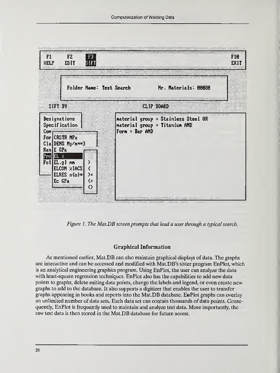
Searching the Database
Data in the system can be searched by indexing terms, alphanumeric field searching, and
numeric range searching. The program presents the user with a series of screen prompts that
are used to direct the search by using Boolean operators. For example, a typical search com-
mand is "Stainless Steel or Titanium and Bar and EL > 15%." This search will locate all bar
materials that are available in either stainless steel or titanium and that have an elongation
greater than 15%. This search can then be stored for future access. In this way, frequently ac-
cessed groups of materials can be segmented from the larger database for quick access and
review. Figure 1 shows the Mat.DB screen prompts leading the user through the typical search
given above.
27
Computerization of Welding Data
i Fl F2 1 FIB
\ HELP EDIT EXIT
Folder Nane: Test Search Nr. Materials: 88888
SIFT BY
Designations
Specification
Con
For
Cla
Ran
Fol
CRSTR nPa
DENS Ng/Ki«»3
E GPa
EL.gl nn
EICON AimELRES n{o}»
Ec GPa
>
<
>=
<=
<>
CLIP BOARD
material group = Stainless Steel OR
material group = Titanium AND
Forn = Bar AND
Figure 1. The MatDB screenprompts that lead a user through a typical search.
Graphical Information
As mentioned earlier, Mat.DB can also maintain graphical displays of data. The graphs
are interactive and can be accessed and modified with Mat.DB's sister program EnPlot, which
is an analytical engineering graphics program. Using EnPlot, the user can analyze the data
with least-square regression techniques. EnPlot also has the capabilities to add new data
points to graphs, delete exiting data points, change the labels and legend, or even create newgraphs to add to the database. It also supports a digitizer that enables the user to transfer
graphs appearing in books and reports into the Mat.DB database. EnPlot graphs can overlay
an unlimited number of data sets. Each data set can contain thousands of data points. Conse-
quently, EnPlot is frequently used to maintain and analyze test data. More importantly, the
raw test data is then stored in the Mat.DB database for future access.
28

Conference Papers—Overview of Computers and Databases
Data Security
Mat.DB provides the user with three levels of password support: read only, read-search,and read-modify. Each database can be separately secured, thereby allowing restricted access
to sensitive data. Users with read-only passwords can browse on the data in established files;
they cannot create files, and they cannot change the data in the database. Read-search userscan search the data and create files, but they cannot edit the data. Read-modify users, typical-
ly the system operator, can edit and search the database. Figure 2 shows the Mat.DB screenprompts that request a user name and password before allowing access to the CarTechdatabase.
Uieu Folder Sift Folder File Operations J til ities
Help File
Pronpt File
Use DOS
Directory
Browse File
Change Disk
Change Director<j
Database
:
CarTech. db
User Nane: iTin Gall
Password
:
Mode : H
MATDB.DB
Figure 2. The MatDB screen prompts requesting a user name andpassword
before allowing access to a database.
29

Computerization of Welding Data
Other Features
Other Mat.DB features include flexible report and print formats, data import and export
capabilities via a standardized data-transfer format, and user-modifiable help and prompt files.
End-users of the Mat.DB system are supported by a detailed user manual, free and unlimited
telephone technical support, and a user newsletter.
During the second half of 1989, Mat.DB will become available for IBM and other per-
sonal computers that use the DOS operating system. Current owners of MetSel/2 will be able
to upgrade to the new program. An OS/2 version will also become available, and work is under
way on a version for the DEC VAX line of computers. The first release of Mat.DB for the
VAX will be compatible with the VMS operating system. An ULTRIX version, DEC's version
of UNIX, should follow shortly thereafter. A major new program for the collection and review
of property data to be entered into the Mat.DB system has been initiated.
Future plans include support for SQL-user interfaces, support for CD-ROM, links with
artificial intelligence programming languages, and integration with finite-element programs or
other calculation programs that require material property data as input. ASM International
views the development of materials property databases as an ongoing project requiring con-
stant attention to keep pace with changing technologies. Work on the development of a com-
puterized materials properties data system will never be completed.
30

Conference Papers—Overview of Computers and Databases
Application of Artificial intelligence to Welding
J.E. Jones
American Welding Institute, Knoxville, Tennessee
Introduction
Artificial intelligence (AI) is a field of study that is difficult to define owing to the breadthof subject matter that is generally included in the definition. Generally, AI can be defined as
the study of logic processes and concepts of understanding which are applied to activities that
are usually thought of as distinctly human in nature.
AI does not necessarily require the use of computers; for many years, researchers havedone a considerable amount of AI work without using computers. The computer, however,
represents a very powerful tool for the application ofAI techniques. Consequently, AI tech-
niues, when coupled with the capabilities of modern computer systems, have produced somenotable results.
Three areas that use AI techniques are being applied to welding applications with somedegree of success:
1. Expert Systems—Expert systems utilize the logic processes of AI and the decision
making "rules" of an expert to make logical deductions. When these deductions are applied
within the knowledge domain of the expert system, the resulting answers are generally the
same as those of the expert whose rules were incorporated into the system. Thus, in some in-
stances, expert systems can be used to replace human experts in decision-making situations.
2. Voice Understanding and Synthesis—^Voice recognition is the simplest of the speech-
related AI efforts. When coupled with expert systems, it can be used for voice understanding
by computer systems. Speech synthesis can take several forms, but the most common and most
useful occurs as text-to-speech generation. Thus, a computer system literally reads out loud to
the user the information stored in the memory (RAM) or off-line storage (e.g., disk, tape) of a
computer.
3. Image Understanding—As computer system speed and capacity have expanded, cam-
era systems have also been developed that can either scan photographic or real images or
image two-dimensional arrays to produce digital representations of those images. By applica-
tion of special numerical analysis techniques, characteristics of those images can be described
by numeric and symbolic representations. Work is being done with Al-based symbolic process-
ing that will lead to understanding of the objects in an image.
Artificial Intelligence Computer Languages
Any computer system can be used to describe and manipulate symbols. Symbols are
stored in the computer memory as a binary digital representation. A computer language can
be used to manipulate and operate on those symbols. However, two schemes, designed to
process symbolic information, have been used to generate two specific computer languages.
The structural characterizations of those two languages, LISP and PROLOG, make symbol
31

Computerization of Welding Data
manipulation much easier. Consequently, LISP and PROLOG were the languages of choice
for many of the successful AI applications systems that have been developed.
PROLOG is used more extensively in Europe and Japan, whereas LISP is chosen moreoften in the United States. Each language is built upon a principle of relationships amongobjects. Neither language is optimized for numerical calculations, except that recursion is
favored over looping or algorithmic execution. Thus, calculations, such as the factorial, are
made more quickly and easily with LISP or PROLOG than a language like FORTRAN or
BASIC.
Expert Systems
An expert system is a scheme developed to emulate the behavior of an expert. The expert
is a person or group of persons with identifiable expertise in a specific area of a particular
knowledge domain. Expert systems take a variety of forms, and when used appropriately, they
can have dramatic results. The most successful expert systems are rule based; they include:
MOTION, for analyzing blood diseases; DENDRAL, for analyzing mass spectrographs; DIP-
METER ADVISOR for determining of subsurface tilt for oil exploration; and WELDSELEC-TOR for selecting steel welding electrodes.
The knowledge representation in a rule-based system takes the form of "If . . .then . ..,"
where the input segment or antecedent specifies a set of conditions that must be met for the
rule to be "triggered." The output segment of a rule or consequent is designed to produce newknowledge in a synthesis-type of expert system or to deduce a specific series of facts in an
analysis-type of expert system. Rule-based expert systems are highly constrained in the know-
ledge configuration. This enables great power in both the analysis of problems and the ability
to build expert systems. However, the constraint reduces the flexibility in the type of problem
than can be solved.
The rule-based paradigm forces a highly constrained format on the structure of the expert
system. Consequently, such a system can include several advanced capabilities. Rule-based sys-
tems offer utilities that answer questions such as how a fact was deduced or why a fact is
needed. This information may be extremely useful to a user who must justify the result to his
superiors or comply with a specific code.
A well-designed expert system shell, using rule-based knowledge representation, offers
several advantages to the expert system developer: rule-transfer superprocedures, parameter
checking, and rule-conflict avoidance. A rule-transfer superprocedure can examine the conse-
quents of a new rule and statistically compare it for form to existing rules. Thus, if the rule
form "seems" out of place to the shell software, it will query the developer. The shell also con-
tains an inference engine, which is the logic drive for the expert system. The inference engine
"decides" which rules to trigger and which rules to "fire" and in what order.
A conventional software system and an expert system differ primarily in their knowledge-
representation methodology (e.g., whether it is rule based) and fti the inference engine, which
is separated fi-om the domain knowledge. With conventional programs, the logic processes and
the domain knowledge are intertwined. The result is a code that is difficult to write and even
32

Conference Papers—Overview of Computers and Databases
more difficult to prototype and maintain. Because an expert system uses a knowledge repre-
sentation scheme and a separate inference engine, it is much easier to develop and maintain.
In addition, an expert system can be "knowledge engineered" by building rules that are simple
for a human expert to define. Thus, development of an expert system that truly mimics the
decision-making behavior of a human expert is much easier.
Representation ofWelding Knowledge
For a computerized welding information system to function, methods must be employedthat allow the information to be stored and retrieved. Computers should also be able to apply
this information to problem solutions. Welding information, as a whole, is the collection of a
large body of knowledge about numerous aspects of welding and welding processes. That
knowledge exists in a variety of forms because each form was useful for a special application.
A computerized information system, therefore, must be able to use knowledge in all these
forms. In addition to a rule-based (production system) knowledge representation, other
schemes can be applied, some of which are discussed below.
Data Structures
The simplest form of welding information is tabulated data. This information has tra-
ditionally been published as relational tables in reference books. However, these tables
rarely exist "out of context" and are often useful only when combined with the broader
scope of information. For example, a table of recommended preheat temperatures related
to carbon-equivalent values is only applicable to a specific set of steels and only for one
carbon-equivalent equation. Consequently, the representation of tabulated welding infor-
mation in a computerized system by using a simple, relational-management system would
be inadequate. A more complex system consisting of a series of relational tables organized
in a hierarchical structure of information must be used.
Rules for Application of Information
Much of the information about welding consists of data combined with rules that define
the application of the data. For example, a welding code may include tabulated data regarding
the type of steels that can be grouped together for purposes of applying a single welding proce-
dure, but also in that code are rules that specify the variations allowed in the procedure for
those steels. The allowed variation is a series of rules which, when combined, form the codified
application of that information. This "production rule" knowledge representation was illustra-
ted in the section describing expert systems.
Graphical and Analogical Knowledge Representation
The design of a welded joint requires not only information regarding procedures, techni-
ques, and materials, but must also include data describing the joint configuration. The joint
groove must be machined to useful tolerances, especially for automated welding applications.
Small changes in joint design can result in substantial cost differences in producing a weld,
which are magnified as the length of the weld seam increases.

Computerization of Welding Data
Welding design information is generally used in the form of engineering drawings and
graphical welding symbols. The representation of this form of knowledge is not well suited to
an alphanumeric database or to production-rule type of information storage. Instead, graphi-
cal and photographic data are required for computerized welding design information systems.
Figure 1 is a typical weld joint and welding symbol graphic representation. The welding infor-
mation system requirements must include provisions to store, manipulate, retrieve, and display
these types of data.
.05
30*
Figure 1. Welding symbol graphic representationfor a typical weld.
Frame-Based Information Representation
Objects can be stored in a computerized representation schema by several techniques.
The frames technique can be used for object representation as well as for structural organiza-
tion of other representations. In a frame-based representation schema, objects are stored by
maintaining information files about the attributes of the object. The frames technique differs
from the database technique in that an inheritance hierarchy is used to describe the objects.
Thus, there could be an object known as "welding electrode" that has attributes such as a
diameter. Then, there could be an object known as "SMAW electrode" that has attributes
such as coating, position, and current type. The object "SMAW electrode" is related to the ob-
ject "welding electrode" just as a child is related to a parent. Thus, the attributes of"SMAWelectrode" include the inherited attribute of diameter.
34

Conference Papers—Overview of Computers and Databases
Expert Systems Technology for a Welding Information System
The American Welding Society now classifies more than 100 welding and joining pro-
cesses. The number of alloys that can be welded with those processes exceeds 5,000. Each of
these alloys, with different compositions and mechanical properties, will exhibit a different
behavior when heated to the melting point and allowed to solidify. Consequently, the specific
welding parameters used to join a material will be unique to that material or, at the very least,
unique to a small, select group of alloys having essentially the same composition and mechani-
cal properties. To specify a welding process and procedure for a fabrication or repair appli-
cation, a welding engineer must be able to specify the particular welding procedure and
parameter values for this application. Depending upon the application, a mistake in the choice
of welding procedure can have catastrophic results, leading to loss of life, significant property
damage, or loss of service for an extended period of time.
An experienced engineer who works with the same group of materials over a period
of time soon becomes familiar with the welding procedures required to produce adequate
welds. It is difficult, however, for an engineer to maintain a complete mental record of the
welding procedures that are applicable to even one broad category of alloy, such as chromium-molybdenum steels, or to ensure that they comply with applicable codes and other standards
designed for those materials. It is virtually impossible for one engineer to recall the informa-
tion necessary to specify welding procedures for the entire range of metals and all possible ap-
plications. A well-versed welding engineer, given a sufficient library of reference information
and sufficient time can, by diligent effort, find a welding procedure for almost any application;
however, this process can result in a less-than-optimum choice. As the complexity of weld
fabricated structures and components continues to increase and as the number of welding
processes and engineering alloys continues to grow, the likelihood that optimum choices will
be made in the specification of welding procedures continues to decrease. For the welding in-
dustry to increase its capabilities, efficient methods need to be found for providing welding
information. This approach will result in optimum use of available resources and will not re-
quire excessive amounts of personnel resources. Studies by the United States Department of
Commerce have indicated that nearly one-half of the gross national product of the United
States is dependent upon welding and joining. Even small changes in the ability to optimize
the use of welding information could have a dramatic impact on the commercial viability of
the United States or any other country. Clearly, then, a computerized welding information
system that can be used for efficient search and retrieval of optimum welding procedures and
that can also provide other useful information about welding and welding materials is an im-
portant step forward and an important undertaking for the welding industry.
The Welding Information Network System
To provide welding information services that are useful for application problem solving,
an integrated system is necessary. Its requirements are (1) the capability to work with a wide
variety of knowledge representation techniques, so that all required information types can be
used; (2) the flexibility and expandability to include future enhancements; and (3) the capa-
bility of being updated to take advantage of the latest computer technology.
35

Computerization of Welding Data
Based on these criteria, the Welding Information Network (WIN ) System was de-
signed and implemented by the American Welding Institute, working with the National In-
stitute of Standards and Technology (formerly the National Bureau of Standards) and the
Colorado School of Mines Center for Welding and Joining Research. The system operates in
a desktop computer environment, which makes it accessible to most potential users.
Knowledge-Base Development for WINThe WIN system is organized as a series of databases coupled with production-rule-
oriented knowledge bases and graphic data systems. Figure 2 is a schematic diagram of the
WIN system structure showing the relationships among the various represented knowledge
sources (AWIKBS) and databases (AWIDB). The WELDSELECTOR expert system ex-
emplifies a hybrid type of expert system, one that was formed by combining a knowledge base
and several databases in WIN. The databases that were combined for the WELDSELECTORexpert system include a materials properties database for more than 1,100 ASTM classified
weldable steels and an electrode properties database. WELDSELECTOR has more than
1,200 rules in the knowledge base that are used for selecting welding electrodes. In each
knowledge base in the WIN system, the technique to represent the knowledge was chosen to
optimize the eventual use of the information.
Win
WQIID- WELDTKOSrEC -
-WtLDSEUCTOK-
-'WeLDSYMTLI
- - WCLOSTRESS-
-
r
-WILDHIAT
nUMAMD—
7J0INC0MfOSE'- —qr
Figure 2. The WIN system structure, showing the relationships amongrepresented knowledge sources and databases.
36

Conference Papers—Overview of Computers and Databases
Expert Systems in the WIN System
All the expert systems in the WIN software network must make extensive use of data;
therefore, they are all coupled with large databases to form hybrid expert systems. Three ex-
pert systems are being used outside the American Welding Institute:
1. WELDSELECTOR, an expert system for optimum selection of welding electrodes. It
includes a database of all the weldable ASTM classified steels and the AWS classified
welding electrodes for SMAW, GMAW, and FCAW.
2. WELDSYMPLE, an expert system for the development of welding symbols. Based onthe ANSI/AWS A2.4-86 document on welding symbols, it produces a graphic repre-
sentation of a welding symbol in a CAD computer environment.
3. FERRITEPREDICTOR, an expert system for selection of welding electrodes based
on ferrite number, according to either Schaeffler or DeLong analysis. This expert sys-
tem was developed in close cooperation with the WRC High Alloys Committee,
Subcommittee on Stainless Steel Welding.
The current WIN system also contains several prototype expert systems that are being
developed for commercial release:
1. WELDSTAINLESS, an expert system for the development of stainless steel welding
procedures. It includes the capability of ferrite number prediction by using both the
Schaeffler and DeLong approaches. It provides comprehensive decision support for
the welding engineering of similar or dissimilar stainless steel welds.
2. WELDHEAT, an expert system for the prediction of optimum preheat and postweld
heat treatment of welded steels.
3. WELDPROSPEC, an expert system for the development of welding procedure
specifications based on the AWS Dl.l structural welding code and on PQRs from a
database system.
Automation Applications
As welding automation becomes more sophisticated, the requirements for information in
automated systems will grow significantly. This need can be met only by a computerized weld-
ing information system, which will require different kinds of computerized information (e.g.,
welding procedures, process control data, digital signal template data for sensor control, and
welding design data for joint tracking control).
Neural Network Simulation
Recent work by the Colorado School of Mines on the WIN system has included investiga-
tion of methods to store, retrieve, and manipulate various types of sensor data for welding
uses. Rapid processing of visual image data can be a monumental task with traditional com-
putational methods. By using a parallel processing environment with a neural network simula-
tion (NNS), the task can be reduced considerably. Because a NNS system does not require a

Computerization of Welding Data
point-by-point or pixel-by-pixel comparison, the time required for identifying images is drasti-
cally reduced, and appropriate decision making is possible without an exact match. Thus, by
using a rule matrix and an image matrix, and then teaching the system in a parallel processor
environment, the system can learn to identify images and begin to "understand" those images
by binding conceptual ideas to the elements of the image.
Artificial neural systems are well suited to robot vision tasks, especially in welding. Neural
networks have several advantages over traditional programs: they deal with noise well; they
can handle more input with fractional time increases; and they can be taught new configura-
tions without reprogramming. In a typical welding situation, spatter and other inconsistencies,
such as poor lighting conditions, combine to give a relatively high noise level. This requires
either a great deal of filtering in a standard vision program or an algorithm that deals with
noise. Since scale up is often necessary to encompass the data necessary to make appropriate
welding decisions, a method that increases computation time fractionally rather than linearly is
preferable. Figure 3 shows a typical interpreted graphic display of a weld joint using the neural
network as it tracks a weld joint.
U Input infornation with certainty factor value of x
y
[jConclusion with certainty Factor value of y
Rule nunber z with conclusion certainty factor value of n
Figure 3. Neural network tracking ofa weld joint.
Tests of the ability ofNNS systems to recognize noisy images have been conducted. Im-
ages were created that contained randomly distributed black spots (spatter). The degree of
noise was determined as a percentage of pixels contained in the weld joint image itself, not in
the total image. This measure of noise has the advantage of being independent of magnifica-
tion or other camera characteristics, but it can report noise levels greater than 100%.
The results of the test indicate that images of welded joints can be processed at a rate ex-
ceeding 600 images per minute. At that rate, 100% accuracy was achieved at noise levels of up
to 130%. Since this NNS system was being operated at approximately 30% of capacity, it ap-
pears likely that it is capable of completely accurate image processing in excess of 2,000 images
per minute at more than a 100% noise level. This is more than adequate to perform real-time
seam tracing for any arc welding procedure.
38

Conference Papers—Welding Applications and Software
CONFERENCE PAPERS -Welding Applications Software
Computerized Software for Welding Engineers
W. Lucas and A.D. Brightmore
The Welding Institute, Cambridge, England
Introduction
Computer systems are commonly available to engineers in a wide range of technologies,
but especially in
• design and drafting
• analysis and modelling
• capacity planning
• manufacturing management
However, until recently, there has been very little specialist software available to help the
welding engineer carry out his many tasks. For example, the welding engineer is increasingly
asked to provide information and advice at the various stages of manufacture. The type of in-
formation required ranges from the initial design of the component and the selection of a
suitable welding process to the best method of manufacture to achieve maximum productivity
with an adequate level of welding quality. If weld defects occur in the course of manufacture,
the welding engineer is required not only to identify the cause, but also to recommend a
solution.
In support of its design advisory service to Member Companies, The Welding Institute
has a number of specialist databases and software (e.g., finite-element analysis of weldments),
which are held on a mainframe computer for in-house use by staff. However, one database,
Weldasearch, which contains abstracts of technical papers relating to welding engineering, is
stored on the Dialog Information Services Computer (Lockheed Missile and Space Com-pany). The company maintains a 22-hour, on-line information-retrieval service that is available
worldwide.^
Over the last four years. The Welding Institute has produced a range of low-cost pack-
ages for use on the desktop microcomputer. The packages range from databases (e.g., for stor-
ing welding procedures) to specialized software (e.g., for calculating preheat requirements
when welding carbon-manganese steels). The subject areas covered are

Computerization of Welding Data
PREHEAT Calculations and analysis of standards and the recommendationof preheat or minimum heat input necessary to avoid hydrogen cracking
The volume of weld metal in any joint type as well as the amountof consumables required
Calculations for estimating the cost of welded fabrications
Advice on GMA welding parameters for steels
Database for the storage and fast retrieval of welding procedures
Set of utilities for use with WELDSPECDatabase for the storage of welder qualification records
providing a constant update ofwhen welders must be requalified
Fatigue design calculations according to the requirements of
BS 5400, part 10
Expert system for generation ofGMA welding procedures for aluminum
Memory-resident unit converter
Several hundred packages have already been sold to welding engineers in the United
States and other parts of the world.
In addition to the use of computers for storing information or carrying out calculations,
current research is aimed at developing "intelligent," or expert systems. A simple definition of
an expert system is one that encapsulates the specialized knowledge of a human expert in a
form that can be accessed by other users. Although it is in an early stage of development, the
prototype systems have demonstrated their capability to provide expert advice (e.g., on the
preferred choice of welding process or equipment).
WELDVOL
WELDCOSTMAGDATAWELDSPECWELDSPEC Utilities
WELDERQUAL
FATIGUECALC
Al-WELD
UNITCALC
Software Packages
There is a dearth of specialized commercial software for the welding engineer, but com-
puters have been used in related tasks. Examples are
• finite-element analysis^"*
5—7• calculation of cooling rates and prediction of preheating
o• selection of welding processes
• fitness-for-purpose analysis of weld defects^
• database for storing welding procedures'^
The Welding Institute software supports the information-technology-related tasks of the
welding engineer. Since the software packages are intended for the j)ersonal use of en-
gineers, they are relatively inexpensive, within the range $30(>-$800. They can be run on the
IBM-PC range of desktop microcomputers and certain IBM "compatible" machines. Typical
system requirements (shown in Figure 1) are
40

Conference Papers—Welding Applications and Software
Machine
• IBM PC, XT, AT, or OS/2
• 256k RAM (minimum)
• 1 floppy disk drive
• 1 fixed disk (for WELDSPEC only)
• cxilor/graphics monitor and adaptor (CGA, EGA, or VGA)
• Epson-compatible printer (optional)
• Microsoft mouse (WELDSPEC and WELDSPEC Utilities only)
Software
• MS-DOS or PC-DOS version 2.0 or later
• IBM BASICA interpreter (PREHEAT, WELDVOL, WELDCOST, and MAG-DATA)
Figure 1. Typical system requirements.

Computerization of Welding Data
PREHEATCracking in welded structures can occur through the buildup of hydrogen and stresses in
the heat-affected zone of the weld. In practice, the risk of cracking can be minimized by con-
trolling the amount of hydrogen generated, the microstructure, or both. As the problem of
hydrogen cracking and techniques to avoid cracking are well-known, various standards have
been produced from which "safe" welding procedures can be predicted. The data in the stan-
dards are presented in tabular and diagrammatic form; they can be used to provide a measure
of confidence that a given welding procedure will be safe for welding a specific type of steel.
In operation, for a given welding procedure and material composition, the data are used
to recommend a minimum preheat level above which the cooling rate of the component will
be sufficiently low to soften the microstructure and also to facilitate the diffusion of hydrogen
away from the joint area (see Figure 2a). Another approach is to use the data to provide
recommendations on the welding procedure, in particular, the minimum heat that can be sup-
plied by the arc while ensuring a safe weld. In this case, by specifying the chemical composi-
tion, preheat level, and hydrogen level generated, the minimum arc-energy input necessary to
control the heating rate will be defined.
The PREHEAT program enables the welding engineer to conduct all the necessary cal-
culations (arc energy, carbon equivalent) to determine the appropriate preheat or arc energy
levels for the avoidance of hydrogen cracking. Thus, an iniportant feature of the program is
the "approved" data published by The Welding Institute^ or British Standards Institute.
Interrogation of the program is via single or multipage entry mode, and four parameters can
be calculated:
• minimum workpiece preheat level
• minimum arc energy of the welding procedure
• maximum hydrogen level of the weld metal
• maximum carbon equivalent of the parent metal
Special features of the program that were designed to make its operation attractive to
welding engineers include
• welding procedure alternatives (e.g., electrode run-out tables) for SMA welding or
current and travel speed options for other arc processes provide procedure
guidelines for calculated arc energy
• numerical and graphical presentation of the results with a printout of input values
and results of calculations
A typical display of welding procedures for carbon-manganese steels in which the mini-
mum preheat level is specified for a particular combination of combined thickness and arc
energy values is shown in Figure 2b.
42

Conference Papers—Welding Applications and Software
Con. thickness
HydxK>sren scalel
Pr^eheat liin •
5Ohm0. 9kJ/»i*B
nesX0285075
100
125
150
175
200
Interpol ated preheat = 63 **C 1
PRESS ANV KEY TO CONTINUE
Figure 2a. Recommendations ofpreheat temperaturefrom PREHEAT.
Electrode win-out lengths in mh - Flat position flpc energvj : l.lkJ/ii
Electrode Discard length
diajieter 128HH
U2. Sim Ifi 12fi 181
3.2WI 2fi 214 112
4.8IW 372 324 m5.iM 511 5« 431
b.aiw
b.3iw
S3& 721 (28
922 883 (84
8.em 14K 1294 UB32322 2823 1723
Electrode data
ElectKde type : |
ElectMde length = 358 MDeposition eff . - i 138K
SUGGESTED pKuCtWiHE - using 388 m froN a 358 nm electrode
>\K Energy : 8.8 kJ/iw
Electrode ciia»»erep : 2.5 mRun-out length : 148 m
Ml - tkve pr^Dcedures are Used on rhe mnimw arc energy hence
the run-Aut lengths N-:)! EE EyiENDED beyond the gi«en values
PRESS flNV KEV TO CONTlHiE
Figure 2b. Weldingprocedure optionsfrom PREHEAT.

Computerization of Welding Data
WELDVOL and WELDCOSTWELDVOL is designed to help the welding engineer carry out the routine and often
time-consuming task of calculating the quantities of consumables (i.e., the number of
electrodes) required for specified arc-welded fabrications. With the keyboard, the user enters
the dimensions of the weld joint, and from these dimensions, the cross-sectional area is calcu-
lated. A typical screen display (Figure 3a) shows how easily the dimensions can be entered.
By specifying the details of the welding process, material type, and total weld length, the
consumable requirements can be calculated. The program is flexible: it can handle all the
major welding processes, the common materials, many types of joints, and different electrode
sizes. A screen display showing the results of a typical calculation is shown in Figure 3b.
To calculate the welding cost per metre of weld, the results from a WELDVOL consult-
ation are used as input data for the WELDCOST program. The weld cross-sectional area and
details of the welding procedure and labor organization are entered into this program. An at-
tractive feature is that the user can vary the individual cost centers (e.g., for consumables and
labor) to determine their influence on the total welding cost. An example of the costings and
cost comparisons is shown in Figure 4.
MAGDATAMAGDATA enables the welding engineer to produce GMA welding procedures for carb-
on and carbon-manganese steel fabrication. The user enters the cross-sectional area, wire
diameter, metal-transfer mode, deposition efficiency, and welding duty cycle. The stored data
are then used to calculate
• permissible ranges of welding current and travel speeds
• maximum and minimum number of runs to fill the joint
Once the appropriate number of runs has been established, the program can automat-
ically generate suitable welding parameters and times:
• welding current, arc voltage, travel speed, wire-feed speed, and arc energy
• arc time, indirect time, and total time per metre
A typical screen display illustrating the results of a MAGDATA consultation is shown in
Figure 5.
44
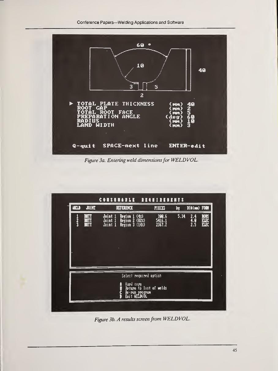
Conference Papers—^Welding Applications and Software
60
40
TOTAL PLATE THICKNESS (mm) 40ROOT GAP (Mn> 2TOTAL ROOT FACE Cnm> 5PREPARATION ANGLE (de^) 60RADIUS (nM> 10LAND UIDTH (rm) 3
Q-€iuit SPACE-next line ENTER-edi t
Figure 3a. Entering weld dimensionsfor WELDVOL.
CIISIIIIII IIIIIIIIIIIS
ULI JOINT PIECE kg BlftdM) im
Joint 1 Segi
Joint 1 Segi
Joint 1 fegi
a 1 mn 2 (82X)
n 3 (147.)
308.6
5416.1
2367.2
Select pequiwd option
I Har<i copy
I )l«tupn to list of velds
• £xit HILMIOL
Figure 3b. A results screen from WELDVOL.

Computerization of Welding Data
ciiriiisii ir cisiiics
mm nocDS h. •f NStim Nttifl : 3 : Cdnmi : Ui\m tet/k
1/1 rhNStilf
^ ! 41.il
1/1 ncCNMm
staiM etstiif
{M.M
1/1 ncom1
hislvF mit efst/faittr tml siit42l.tl
ki:- IteNft HnMft DNtnai ctst IMMit
Figure 4. A costing comparison chartfrom WELDCOST.
transfer HOd
ition efficia
Figure 5.A screen ofintermediate resultsfrom MAGDATA.
46

Conference Papers—Welding Applications and Software
WELDSPECWELDSPEC is a database for the storage and retrieval of welding procedures. The infor-
mation is that required for approval of a welding procedure on the standard welding-proce-
dure sheet; i.e., component details, welding parameters, consumables, and results of inspection
and mechanical testing, can be stored in the database.
In designing the database specifically for welding procedures, the following operating fea-
tures were considered to be highly desirable:
• The system must be extremely easy to use since it will be accessed by nonspecialists
in computers.
• Information should be displayed in a manner similar to that on the procedure sheet.
• The system should contain a graphics capability for drawing components and joint
details.
• The program for accessing information should be menu-driven with full prompting
at all levels.
An important feature ofWELDSPEC is its user friendliness. Each item of procedural in-
formation is typed into the box reserved for that information on one of the seven screens that
represent a full welding procedure (see Figure 6a). Diagrams can be entered by means of a
mouse and a drawing package; a typical schematic drawing is shown in Figure 6b.
Figure 6a. One ofseven text screens that represent a WELDSPEC weldingprocedure record.
47

Computerization of Welding Data
Figure 6b. A diagram showing a tube-to-tube plate weldfrom WELDSPEC.
mm Of HQJING nOCEHK
Procedure details, PAGI OHE
Mi ItkOct 1!
" "- Bob Spiller h |
h y| - ^ w S]iielde<( wetaT arc . K-ij:
fe/^ Shielded natel arc _ pHi:'
sided/unbaclc ffiT^P
0IKoot ran verfical dom Pip Mgjietep Saftge t. 5 incli and mn
l: i Otter
Figure 6c. Entering data by the use ofmenus in WELDSPEC.

Conference Papers—Welding Applications and Software
To extract one or more welding procedures, the user may specify any of several mainsearch parameters for which instantaneous searches can be made:
• welding process (main and root run)
• joint type
• welding position
• parent material type
• parent material thickness range
These searches are made, by using a mouse, from menus that are overlaid on the screen,
as shown in Figure 6c.
The user may also search through the database for the occurrence of sequences of charac-
ters, enabling searches to be made on other information, such as material properties, con-
sumable trade names, and company welding procedure.
Once located, welding procedures can be printed out in a standard format, or the unique
catalogue number of the procedure can be used to find the original procedure document.
WELDSPEC Utilities
This package, complementary to WELDSPEC, was designed to enable the user to
manage the welding procedure database created by WELDSPEC in the most efficient man-
ner. It contains routines to facilitate the following tasks:
• additional printout routines
to print a welding worksheet
to print a sorted, summary register of welding procedures
to print a batch of PQRs
• data management routines
to import or export procedure data to other WELDSPEC systems
to back up and restore data from floppy disks automatically
• graphics conversion route
to convert diagram from CGA format to EGA or VGA format
WELDERQUALWELDERQUAL is a database package designed to store welder qualification informa-
tion. Having entered details of all the qualification data, the welding engineer can keep track
of the work force on computer, helping to ensure that (1) qualifications that are due for
renewal can be found quickly and easily prevented from lapsing unnecessarily, (2) suitably
qualified welders are assigned to perform certain types of welds, and (3) unnecessary qualifica-
tion tests need no longer be carried out, since a rapid search of the database will inform the
user immediately if any welders already hold a qualification for a particular kind of weld. Atypical screen display showing the format of a welder qualification record is shown in Figure 7.
49

Computerization of Welding Data
Figure 7. Theformat ofa WELDERQUAL welder qualification record.
I
FATIGUECALCThe FATIGUECALC program enables designers to perform fatigue design calculations.
Both constant and variable amplitude loading are handled by the program, and if desired, the
following corrections can be applied to the S-N curve used in the calculation:
• plate thickness
• unprotected joints in a seawater environment
• allowance for toe grinding
FATIGUECALC is a spreadsheet-style program with extensive help capabilities for
those not familiar with computers. It enables experienced designers to perform complex cal-
culations quickly and accurately. Graphics are used to plot stress range and fatigue life
together with the appropriate S-N curve.
Details of the calculations can be printed out in two forms: a one-line summary of the
numbers and other parameters used or a full-page description suitable for inclusion in a
report. Typical results of a FATIGUECALC calculation are shown in Figure 8.
Stress spectra, input parameters, and calculation results can be communicated to and
from other programs via standard ASCII files.
50
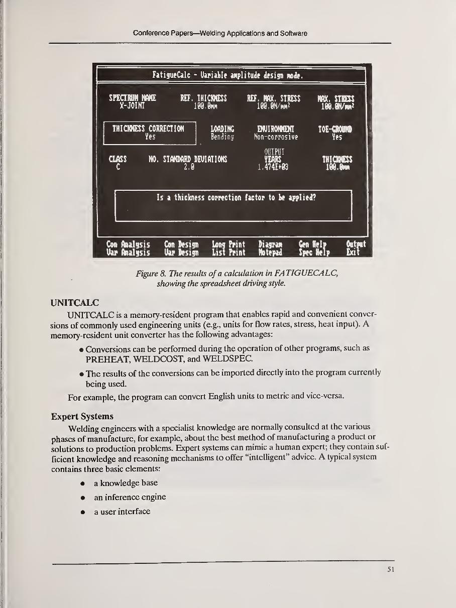
Conference Papers—Welding Applications and Software
FatigueCalc - Uvialle Mplitude d»sip no^.
X-JOIHIREF. THICKNESS REF. m. STRESS m. STSK
THIOSSSS CORRECTION miNGBending
DwiRommNsjn-corrosive Us
(mt NO. STANDARD DEUIATIONS
C 2JYEARS
1.4741+83
Is a thickness comction fictor to mliii^
Cm flulisis Cm Sesi^n im Priat liisran Gn iklv Ottfit
UipflHlisis Uapteip list hint fetepia Spw itlp hd\
Figure 8. The results ofa calculation in FATIGUECALC,showing the spreadsheet driving style.
UNITCALCUNITCALC is a memory-resident program that enables rapid and convenient conver-
sions of commonly used engineering units (e.g., units for flow rates, stress, heat input). Amemory-resident unit converter has the following advantages:
• Conversions can be performed during the operation of other programs, such as
PREHEAT, WELDCOST, and WELDSPEC.
• The results of the conversions can be imported directly into the program currently
being used.
For example, the program can convert English units to metric and vice-versa.
Expert Systems
Welding engineers with a specialist knowledge are normally consulted at the various
phases of manufacture, for example, about the best method of manufacturing a product or
solutions to production problems. Expert systems can mimic a human expert; they contain suf-
ficient knowledge and reasoning mechanisms to offer "intelligent" advice. A typical system
contains three basic elements:
• a knowledge base
• an inference engine
• a user interface

Computerization of Welding Data
The distinction between the knowledge base and static database of a conventional pro-
gram, such as WELDSPEC, is that the knowledge is stored largely as statements about uncer-
tain facts and rules, and as more information becomes available, the knowledge base grows.
Since WELDSPEC simply involves the data storage, it has been written in "C," which is a con-
ventionally structured programming language. Many areas of engineering, such as the solution
of problems, are subjective or poorly defined and, therefore, not well suited to conventional
methods of programming. However, these subject areas can be modelled by using an expert-
system approach.
An expert system usually gives advice as its output, not definitive data, that is, it tends to
recommend a certain course of action rather than to specify parameters. This resembles the
way a human expert would state his conclusions; for example, "In the circumstances you have
described, my recommendation for reducing undercut would be to reduce the torch travel
speed."
An expert system should have extensive explanatory facilities. In the same way that a
human expert explains his line of reasoning, the computer should be able to answer the follow-
ing user questions:
What does that question mean?
Why have you asked that question?
How have you arrived at that conclusion?
Expert Systems in Welding
A number of expert systems in the field ofwelding technology have been reported:
TIG 14
Weldselector:15
Weldex16
17Robot diagnosis: a system to diagnose malfunctions in ASEA robots by Ford (U.S.)
a system designed by Framentec for the diagnosis of faults in GTAWequipment
a system for the selection of wire and electrodes from consideration
of the parent material and welding positions
a system for the automatic inspection and interpretation of pipeline
radiographs
At The Welding Institute, a system has been produced for generating welding procedures.
A rule-based shell was used that is capable of handling probabilities. It also provides a means
of accessing externally written programs, such as tables of data or graphics routines for
diagrams.
52

Conference Papers—Welding Applications and Software
Welding procedure specification
Initialspecifications
ConsumableDetails
Weld preparation& run sequence
Cleaning &
heat treatment
Weldingconditions
Parent materialtype(s)Thickness (es)
Welding positionQuality requirementsService conditions
Filler materialShielding gas
Weld preparationPreparationBacking detailsRun sequence
Pre-weld cleaningPreheat temperaturePreheat methodInterpass temperature
Interpass cleaningPost weld heat treatment
VoltageCurrentTravel speedArc energyWire diameterNozzle diameterGas flow rate
Figure 9. The structure ofa weldingprocedure specification.
Figure 10. Graphics "help"from the weldingprocedure generator.
53

Computerization of Welding Data
The expert system is capable of generating aluminum GMA welding procedures. The task
of generating a welding procedure may be divided into five sections, each of which may be sub-
divided into the individual items that constitute a welding procedure specification (Figure 9).
The user of the system may either progress completely through a consultation or simply use a
single section of the program if, for example, information is required only on which con-
sumable to use for a particular combination of parent metals and service conditions. The sys-
tem may, therefore, be thought of as being knowledgeable in the domain ofGMA welding of
aluminum rather than simply as a welding procedure generator.
As the program progresses through a consultation, evaluating each item of a welding pro-
cedure in turn, it requests information from both the user and external data files. The results
of major decisions are displayed on the screen at the end of each section of the consultation,
giving the user the opportunity to disagree with, and if necessary, override the program's
recommendations. The user is also presented, where necessary, with screens giving a graphical
representation of certain pieces of advice, such as the details of recommended edge prepara-
tions or different welding positions (Figure 10).
At any point in a consultation, although usually after all five sections have been evalu-
ated, the user may request a hard copy of the advice given.
References
1. R.T. Bryant, The Role of On-line Services, The Metallurgist and Materials Technologist, vol. 5, no. 6, 1982,
pp. 245-246.
2. H.A. Nied, The Finite Element Modelling of the Resistance Spot Welding Process, Welding Journal, vol. 63, no. 4,
1984, pp. 123s-132s.
3. S.S. Glickstein and E. Friedman, Welding Journal, vol. 63, no. 9, 1984, pp. 38-42.
4. J.C. Ian, "Modelling the Microstructural Changes in Steels Due to Fusion Welding," Ph.D. Thesis, Lulea
University of Technology, 1984.
5. O.W. Blodgett, Calculating Cooling Rates by Computer Programming, Welding Journal, vol. 63, no. 3, 1984,
pp. 19-35.
6. V. Mehrotra et al., A Microcomputer Method for Predicting Preheat Temperatures, presented at the inter-
national conference Welding for Challenging Environments, Welding Institute of Canada, Toronto, 1985.
7. M. Spiegler and R. Volke, Computer Program for the Determination of Hardness in the Heat Affected Zone of
Steel Welds, Schweissrechnik, Berlin, vol. 30, no. 11, 1980, pp. 511-512.
8. P. Weisner and N. Gutzner, Selection of Special Welding Processes, Zis Mitteillungen vol. 23, no. 1, 1981,
pp. 13-21.
9. W.S. Burle, Program Aids Computer Plotting of Weld Flaws, Oil and Gas Journal, vol. 83, no. 9, 1984, pp. 91-94.
10. V.G. Marshall and A.C. Boother, A-Weld: An Integrated Suite of Programs for Welding Engineers, presented at
the international conference Computer Technology in Welding, The Welding Institute, London, 1986.
1 1. W. Lucas, Microcomputer Systems, Software, and Expert Systems for Welding Engineering, Welding Journal, vol.
66, no. 4, 1987, pp. 19-30.
12. F.R. Coe, "Welding Steels without Hydrogen Cracking," The Welding Institute, London, 1973.
13. "Process of Arc Welding of Carbon and Carbon-Manganese Steels," BS 5135, British Standards Institution, 1984.
54

Conference Papers—Welding Applications and Software
14. P. De Bonnieres et al., A Knowledge-Based Diagnosis System for Welding Machine Problem Solving, paper
presented at international conference Computer Technology in Welding, The Welding Institute, London, 1986.
15. J.E. Jones and W. Turpin, Developing an Expert System for Engineering, Computers in Mechanical Engineering,
November 1986, pp. 10-15.
16. S. Mahalingam and D.D.Sharma, Weldex—An Expert System for Nondestructive Testing of Welds, presented at
the second conference on AI Applications, IEEE Computer Society, December 1985.
17. Article inAmerican Metal Market/Metalworking News, April 21, 1986.
55

Computerization of Welding Data
Computer Applications in Welding
B. Chew
Marchwood Engineering Laboratory, CEGB, Southampton, England
Introduction
This paper describes some of the areas in which the Central Electricity Generating Board
(CEGB) has been using computers to handle welding information.
Welding Procedure Storage and Retrieval
MELSPEC is a welding procedure specification (WPS) and procedure qualification
record (PQR) database program that has a number of characteristics in common with other
systems and also some features that are special to the CEGB. The system is a compiled
DBASE III program operating on three system databases, two of which store welding proce^
dures and one that holds the PQR information. The program also supports a variable numberof personal databases, which are the destination for edited WPSs.
The particular database structure ofMELSPEC illustrates one of the issues that must be
addressed when setting up a company system, namely the need for the program to reflect the
company's in-house logic for handling WPS and PQR information. In this context, commercial
software is limited in value unless it is tailored to meet these specific requirements.
Thus, the CEGB maintains, in effect, two corporate WPS databases, the larger containing
essential welding variables for a very wide range of materials and weld types, and the smaller,
the fully worked-up procedures. The PQR database contains the standard weld approval infor-
mation needed by the welding engineer to check and avoid disqualification of a WPS that is in
the process of being edited for a particular application. This ability to edit corporate WPSs to
meet local, plant-specific needs and to maintain an archive of these procedures for future ref-
erence is an important requirement of the system that is met by the multiple personal database
facility.
Although the type of information given on a WPS is common to most users, the style or
layout of a WPS is often very specific to a given company. Welding engineers are very reluc-
tant to make changes to suit the computer; rather, they expect the machine to mimic the
familiar house style. With a programmable language such as DBASE, this requirement is not
too difficult to meet. MELSPEC presents its WPS information in a screen layout that emu-
lates the CEGB style but stores the data as a conventional database.
Welding procedures are printed out as required onto a pro forma with blank spaces to be
filled in. Pro formas are used because the printing quality of standard, inexpensive, dot-matrix
printers, although improving, is still much poorer than that of typewriters or typesetting
machines.
56

Conference Papers—Welding Applications and Software
Because most WPSs are drawn up to meet standard situations, weld preparation and heat-
treatment diagrams are predrawn. However, the program has a graphics interface, whichenables user-defined drawings to be incorporated. We hope to exploit this aspect in the future
in the area of specialist plant-repair procedures.
Weld Modelling
METWELD is a weld modelling program for thick-section manual metal arc (MMA)welds. The program was originally written in Hewlett Packard Basic and then nearly com-pletely rewritten in Pascal. It provides the welding engineer with a rapid evaluation of the
microstructure and cost implications of a range ofMMA welding options.
Features of the program include variable weld preparation geometry and a built-in mate-
rials database. The program output is in the form of a graphics display of the modeled weld
cross section that shows the position of the weld-bead layers together with their associated
heat-affected-zone (HAZ) isotherms at the sidewall. The isotherms computed are the Acl,
Ac3, fusion line, and a critical-grain-size isotherm. Separate capping electrodes may be speci-
fied so as to control the HAZ at the outer surface of the weld. The program also gives a sum-
mary of costs associated with making the weld.
Several databases are used by the model. For the base materials, these include data on
grain-growth characteristics and transformation temperatures, which have been determined
by using weld simulation techniques.
Extensive bead-on-plate trials have been carried out in the laboratory to generate bead-
shape data for a number of commercial electrodes. Bead height, penetration, and width were
measured as a function of welding position and weld preparation angle and related to welding
conditions.
Expert Systems
While their potential in the long term is considerable, expert systems have yet to make
any serious impact in the welding area.
The CEGB, in common with others, has been going through the "learning curve" in the
expert systems field. It is currently working with the University of Southampton to develop a
welding process selector for the welding of thin-section austenitic tubes.
From this exercise, the CEGB has learned the importance of the user interface and that
the system should be essentially advisory. Users felt restricted by the way the first version's
program was structured to lead inexorably towards a single conclusion. The revised program
presents the user a list of options with ratings alongside that change during the session,
depending on how the questions are answered. The questions remain on the screen through-
out the consultation, and a HELP facility is provided to explain any questions that are not
clear to the user. Changing the program to be advisory rather than assertive has produced
significant improvement in user acceptance.
57
Computerization of Welding Data
An earlier expert system model was built to generate welding procedures from the com-
prehensive knowledge base available on the welding of high-temperature materials and the AIlanguage SAVOIR. This turned out to be a valuable development exercise, but its usefulness
was limited by the fact that such procedures were already available! The lesson here was that
the requirement must be clearly identified at the outset and then applied to the appropriate
solution. In this case, welding engineers needed a welding procedures database rather than an
expert system.
The CEGB is currently interested in the development of real-time control systems for
welding processes. The role of the expert in this context is to be in charge of a conventional
control system that would intelligently interpret the performance of a process and adjust or
control the process parameters accordingly. This in-process control function is normally car-
ried out by a human operator, who assimilates information on the progress of the weld by
using his sight, hearing, and knowledge derived from training and experience. The expert sys-
tem should simulate this operator's judgment.
Process Control
Computers are used to control the welding process by processing sensory data from a
weld and detecting and controlling the onset of penetration. This requires real-time processing
of data in a closed-loop configuration where the computer is in charge of, say, the welding
power supply. Systems have been built that view either the weld back face or front face. In the
former case, penetration can be sensed directly, whereas in the later, it must be inferred.
A recent novel development has been to observe and analyze the spectrum of weld-pool
vibrations that either have been deliberately induced or occur naturally when the current is
pulsed. This information is used to predict the onset of penetration and to control arc power
in response to changes in the pattern of heat flow away from the weld. These changes in heat-
flow patterns may arise, for example from changes in section thickness. The system has been
named MELODY-MEL oscillation dynamics for control of penetration in welding.
Registration ofWelding Personnel
Rapid developments have been taking place in the United Kingdom regarding the estab-
lishment of database registers for welding personnel. Three registers are being established
under the auspices of the Professional Board of The Welding Institute to cover welding en-
gineers, welders, and supervisors. The Welding Engineer Register was successfully launched
in January 1987. The Welder Register will be introduced in November 1988. The Supervisor
Register will follow as the role of this newer category of personnel becomes more clearly
defined.
These changes are timely; the pressures on industry to provide adequate quality assurance
systems to control the manufacturing process are increasing. The CEGB sees considerable
scope for these registers and anticipates that they will provide a ready framework for assessing
the competence of welding personnel by second- and third-party organizations undertaking
approval of manufacturers and contractors to British Standard 5750.
58
Conference Papers—Welding Applications and Software
The Welder Register will particularly benefit the power industry; their welder population
is mostly migratory and there are difficulties in verifying the approval status of potential
welders.


Conference Papers—Welding Case Studies
CONFERENCE PAPERS- Welding Case Studies
Update on Procedure Qualification Recordsand Weiding Procedure Specifications
H.G. Ziegenfuss
American Welding Society, Miami, Florida
Among the top welding data needs that were identified in the Computerization of Weld-
ing Information Workshop were procedure qualification records (PQRs) and welding proce-
dure specifications (WPSs). These needs were recognized long before the workshop gave
them priority, but I will briefly report only the recent events and my outlook on the future.
The Welding Research Council (WRC) has been deeply involved in a very extensive pro-
gram to provide hundreds of PQRs to support the development of standard WPSs. Since the
focus is on computers, I will neglect the aspects of welding, but I want to report the status of
the procedures.
The first ten WPSs have been balloted through the WRC Welding Procedures Commit-
tee and two technical levels of the American Welding Society (WPS). The various committees
have also reviewed the data format and have agreed with the current version. I do not have an
example because it is still in the balloting process and has not been released for public com-
ment yet. The final ballot is expected to be completed by the end of the year.
The voluntary consensus process that we follow is very important to the welding commun-
ity that we serve. It has been described as both a curse and a cure. The curse is that it takes a
long time to resolve all points of view. The cure is that the final result is virtually a liability-free
product. I expect to have this first group of WPSs published before the next AWS Welding
Show.
What do I think will occur in the future? Many more standard WPSs are required to satis-
fy the needs of the industry. As soon as the first WPSs are published, there will be a clamor for
the committees to produce more. It will require a substantial increase in effort to produce the
additional procedures, and additional funding will be required to support the effort. Both
WRC and AWS will be working on this issue. By the time the third conference is held, I hope
to report that significant progress has been made.
61

Computerization of Welding Data
Computers in Welding—from Breadboards to Desktops
F.R. Baysinger
R.A. Hanson Company, Inc., Spokane, Washington
Introduction
Maintaining welding procedure and operator qualification records, listing welders whohave worked on specific jobs, and calculating design and shop-layout information are ways
in which pressure-vessel and heavy-plate fabricators have used computers for nearly four
decades. In more recent years, typical applications include computer stress analysis, computer-
aided drafting, and programming numerical controlled machines with PCs. There are many in-
house programs to do welding-related tasks, but these generally are well-kept secrets. Somenew programs have been written specifically for the welding industry; some are available now;
others will be available soon.
History of Computers
Imagine a room with metal shelf racks arranged wall-to-wall in rows with little space be-
tween them, the shelves solid with vacuum tubes, and bird nests of wiring plugged into pull-out
drawers. These drawers were aptly called breadboards, and the metal racks, the mainframe. In
a room adjacent to the mainframe, a control panel covered most of the wall, polka-dotted with
panel lights busily winking on and off in green and red. This describes the IBM 650, a com-
puter that was up and running in 1951. This computer used the familiar do-not-fold-or-spindle
punch cards that required keypunch and card-reader hardware. The 650 had a 2,000-word
capacity, used a language called SOAT, and had math functions comparable to a modern $5
hand-held calculator. The hand-held alphanumeric computers with an attached tape printer
and 2 kilobytes of memory of ten years ago had a capability similar to that of the 650.
In 1951, a large pressure vessel and heat exchanger manufacturer, with plants in Canada,
New York, Pennsylvania, and Texas, kept records on roughly 800 welders involved in code
fabrication. In addition to the welding procedure and operator qualification records required
by the ASME Boiler and Pressure Vessel Code; the Navy, Air Force, and the Army each re-
quired operator tests, not necessarily accepting those of ASME. Likewise, many of the major
oil and chemical companies required operator qualification tests witnessed by their own inspec-
tors. The qualifications expired and required retesting at different intervals. To maintain these
records and retest dates manually, two full-time clerks and a typist were needed.
When we stored the records on keypunch cards, we were able to provide each plant with
a list of their approved qualified welders and expiration dates, plus printouts of the dates and
hours these welders had worked on any job. This virtually eliminated the problems of welders
working on jobs for which they did not have qualification approval. One part-time keypunch
operator maintained the system.
62

Conference Papers—Welding Case Studies
Almost forty years later, many companies maintain similar records , but they are gener-
ated with word processors using in-house-developed programs or spreadsheet-type programs.
Twenty years ago, time sharing came into use. Keyboard work stations, called "dumb" ter-
minals, with black-and-white video displays were attached to the company's mainframe or to a
larger computer somewhere else, even in another city. FORTRAN was the favored language.
As a user, one encountered frustrating delays when the terminal simply went dead because the
mainframe was ignoring the task. Although tedious to format, its capabilities for mathematical
computations, interactions, and printing pages of tabular data were much more valuable than
the one-number output of the then-$100 hand-held calculators.
We used the time-share system to write some powerful programs, some of which are in
use today by the companies for which they were developed. One of these programs asked a
few simple questions about the dimensions of a spherical tank. From this, the computer would
produce a detailed plate layout, required ingot size, the stock-plate dimensions, the blank-cut
dimensions, the finished-plate contoured dimensions, andx-y coordinates for flat layout of cut-
to-size plates before forming. The computer also calculated the price per pound and printed
bills of material for the entire tank. This took twenty minutes.
At the same time, twenty years ago, engineers frustrated with the slowness of the time
shares started building their own computers. Some built them in their garage at their own ex-
pense; others built them at the office at company expense. We used one that had a nest of PCboards, desktop size. It handled the complicated engineering programs we had written as well
as the big mainframe computer. These computers were improved, made smaller, and became
the personal computer.
The success of some of these engineers, as well as the established companies, in market-
ing their creations led to a proliferation of personal computers. The user was confronted with
noncompatible operating systems (such as CPM and DOS), with the possibility of the com-
puter manufacturer going out of business, and with worries about software availability.
To compound these problems, professional programmers, who had never done anything
but accounting, started to write software, and thus the "post-office-box" age of computing
began. A small fortune would buy a floppy disk, a shelf full of books, and a second shelf full of
third-party books to make sense out of the first set. With all this, you could now stuff a number
in a mailbox, multiply it by a number from another mailbox, and stuff the result in a third mail-
box. You could also print the results in huge tables and even exchange column locations. Some
of these programs require patience and time to learn to use, and any numerical errors can lead
to costly errors in the output data. Programs written by programmers may not fit engineering
needs, and often the engineers have neither sufficient programming skills nor the time to write
useful programs for themselves. ASM is attempting to solve this dilemma with some tutoring
disks on programming that are available now.
Meanwhile, the machine-tool industry developed a host of numerical-controlled shears,
press brakes, die-punch machines, profile cutters, milling machines, and more, that are in use
today. The programming method for these varies from shop-floor punch-in to computer-con-
trolled input from a time-shared computer in another city. An automatic culvert-making
63

Computerization of Welding Data
machine produces any diameter or length of corrugated culvert; the entire plant is controlled
with a 64-kilobyte home computer with data loaded from a tape cassette. In Trieste, Italy,
there is a computer drafting room with 20 D-sized plotters that completely design a ship, downto individual bracket drawings. Japan has out-of-chamber electron-beam welding of two-inch-
thick stainless steel pipe, with the parameters controlled by microprocessor. The latter two
were observed in the mid-1970s.
Also available in the early 1970s were several mechanized welding travel carriages with
wire-feed units and rack-positioned torches. Within a short time, powered weaving and torch-
height positioning were added. Next came some very sophisticated systems with all of the
above plus one to three torches and push-button control of travel and wire-feed speeds, first
with analog and then digital readout. The wire-feed manufacturers picked up on this and
started adding wire-speed readout to the wire feeders, even though most welders had no idea
how to use it. Operator ignorance led to the abandonment of the exotic travel systems or, at
least, their advertisement. This is sad, because the production can be increased as much as
1000% by the use of multiple torches—one operator running ten GMAW or SAW heads at
once.
Trade journals, sincerely wanting to be at the cutting edge of technology, are filled with
articles about robotics, flexible manufacturing systems, video comparators, and machine-vision
quality control. ASME, with CIME magazine, presents high-level articles on the manydevelopments in this field. The users of this technology seem to be aircraft manufacturers, the
automotive industry, and other high-volume industries.
Many shop production managers in smaller industries, unable to justify a million-dollar in-
tegrated work station in typical one-of-a-kind situations, could only hope to improve their
production with some simple torch-holding or moving devices. Many of these devices could
produce at a unit rate close to those of a robot and at a far lower unit cost because of reduced
labor.
For the engineering group, an almost overwhelming collection of software was available,
mostly post-office-box style, but there were some programs related to simple design. The first
huge finite-element programs could be rented, then purchased, and now bought at reasonable
prices. The finite-element programs are still expensive to implement because of the long learn-
ing time and the time required to enter the node coordinates. Computer-aided-design (CAD)programs for drafting were at first prohibitive, but now they are common. The trend toward
these systems is so strong, that high schools should be teaching computer drafting. The trade
magazines give much space to three-dimensional drafting, stress analyses by color shadings,
and more, but users seem to be the automotive and aircraft industries plus the academic com-
munity.
The development of the supercomputer, such as the Cray, and the developmental work in
parallel processing systems should be mentioned, because, they may affect the competitiveness
of U.S. industry. Look for time-shared use of these supercomputers to be available.
64

Conference Papers—Welding Case Studies
Current Systems, Software, and Trends
The combined efforts of the Japanese electronic industry to develop a standardized
operating system for all their computers could cause U.S. systems to become obsolete, unless
similar U.S. efforts are initiated to develop a better system. For the moment, the emphasisseems to be on 386 chips. The development of PCs that can use three operating systems
(DOS, OS/2, and Xenix) is encouraging. There are also third-party boards that enable bothDOS and Macintosh to be used in a DOS-type computer.
There is a trend toward better software manuals, tutoring discs, or even better, software
requiring neither manuals nor tutoring. Shop programs should allow the user to select their
program with one key and enter their data directly or by a selection of multiple choices. Theoutput should appear on a monitor and a hard copy.
Programs useful to the welding industry would
• estimate welding time and filler-metal requirements
• calculate a bill of materials for a welding job or quote
• control qualification tests, both procedure and operator
• match existing qualification procedures against ASME Section IX or
AWS Dl.l requirements
• control production schedules, equipment loading, and manpower
• write ASME or AWS procedures
A program for estimating arc time and filler requirements for any arc process in any joint
design, WELDBEST, is now commercially available. It will also write AWS procedures. A pro-
gram, Primavera, will handle virtually all the requirements for scheduling, but it requires tutor-
ing and an intensive learning period. Programs for matching existing procedures to ASME and
AWS requirements are being developed. Computer design programs can prepare bills of
material for quotation or production.
Parameters for Wire-Feed Processes
For shops that have mechanized welding equipment or arc-welding robots, some of the
setup weld testing can be eliminated by calculating the starting conditions for any welding
process that uses a wire feeder. In fact, a PC containing this system can be used to control real-
time welding, provided accurate measurements are made of v^re speed, deposited metal
weight and volume, and travel speed. Real-time control is also affected by the type of power
supply, control of wire contact-tip-to-work distance, effectiveness of proximity controls, and
parameter-control circuitry.
65

Computerization of Welding Data
The basic conditions for a wire-feed welding process are
1. A given volume of wire feeding into an arc at a constant speed will deposit essentially the
same volume of weld metal in a given time.
2. The volume of the weld deposit changes directly with wire-feed-speed and inversely with
travel-speed changes.
3. The volume of weld metal going through the arc is equal to the cross-sectional area of the
wire times the length of wire passed through in a given time:
V = 3.1416d^U4 (1)
where v = volume, d = diameter, and / = length of wire going
through the arc
It is easier to work with cross-sectional area than with volume:
a = wckft ' (2)
where a = cross-sectional area of deposited bead
c = cross-sectional area of wire
k = a constant: 1.0 for bare wire; 1.0 for FCAW or SAWwith iron-powder additions
t = travel speed of torch
w = wire-feed speed
To find the weld-travel speed required to produce a bead of a desired cross-sectional area
at a known wire-feed speed, the relationship is
t = wckja (3)
For proper wire-feed speed to give a bead of desired area where travel speed is known(as in a two-torch setup on a single-travel carriage), the equation is
w = ta/(ck) (4)
Most available welding-deposition-rate data relate pounds deposited per hour to
amperes. The relationship between wire-feed speed and amperes for a particular process is
not readily available, except for aluminum. A family of curves will result, for example, for the
GMAW process, and the deposit rate varies with shielding gas and contact-tip-to-work dis-
tance. Deposition rates of the SAW process are also sensitive to contact-tip-to-work distance.
When the equations are applied to actual welding situations, they are very accurate whenconstant-current power supplies and constant-speed feeders are used and only "ball park" ac-
curate with constant-voltage power supplies, depending on slope characteristics. The amountof metal deposited seems to be consistently greater than the amount calculated; no one has an
explanation.
Welding operators use these equations, and they are useful in training operators of
machine-welding setups, especially those with multiple torches.
66

I
Conference Papers—Welding Case Studies
Summary
The welding industry has used computers for welding-related tasks for nearly four
decades, but the programs have been proprietary. Commercial PC programs are helpful, but
they may require a significant learning period to apply them to welding fabrication.
Welding parameters for mechanized welding setups can be calculated, provided the wire-
feed speeds versus deposition rates are known.
Specific welding programs are now commercially available for PCs.
I
i
67

Computerization of Welding Data
WELD IMPROVEMENT PROGRAM:WELD AND WELDER TRACKING SYSTEM
W. Newcomb
Potomac Electric Power Company, Washington, D.C.
Introduction
A significant portion of the O&M and capital projects of the Potomac Electric PowerCompany (PEPCO) involve welding. Welding is performed on a large number of critical com-
ponents in PEPCO's generation system. Failure of those components almost certainly results
in loss of generation revenue, and in some cases, could result in injury to PEPCO personnel.
Many failures can be directly related to the quality of welding during repairs and installation of
these components. Consequently, welding quality is of prime importance to the Generation
Group. In a constant effort to improve weld quality, PEPCO has established a Weld Improve-
ment Program. One of the main components of the program is a Welder Tracking System, a
reliable record of welders' performance and qualifications.
The American Welding Institute (AWI) was chosen by Edison Electric Institute (EEI) to
study the feasibility of using a computerized database system for tracking welder qualification
history and to suggest a "generic" system to be used by all EEI members.
AWI created a prototype system based on data from the normal operation of a power
plant. PEPCO was chosen to supply the data. The success of the prototype established the
feasibility of the database system.
Objectives
The program to implement a computerized system for welder tracking incorporates the
overall objective of the EEI-AWI feasibility study: to develop management tools to improve
the quality of welding in the construction, repair, and maintenance of electric generating sys-
tem components. Two specific objectives were also established: (1) to improve the welding
quality of PEPCO contractors so that PEPCO derives the maximum quality consistent with
schedule and budget constraints and (2) to increase the productivity and effectiveness of
project management and inspection personnel.
The EEI/AWI study concluded that the implementation of a computerized welder track-
ing system could greatly improve the quality of welding when applied appropriately using good
management principles. The two specific objectives of PEPCO were attainable through the
achievement of more specific goals.
68

Conference Papers—Welding Case Studies
Goals
The success of the computerized welding tracking system depended on designing a system
that was simple, flexible, economical, integrable, historical, capable of providing information
about contractors, and capable of process control.
1. The system must be simple for the user to apply to the problems encountered in welding
project management, from data entry through the use of color-coded, interactive data
entry and update screens. A menu-driven program that both data-entry and project-
management personnel could use easily was also required.
2. The system must be easily altered, especially the area that generates reports. Although
considerable effort is expended in developing a system that meets all the needs of the
Generating Construction, Production, and Quality and Reliability Departments, it is
impossible to foresee all potential applications.
3. The system must be relatively inexpensive to produce (not requiring restructuring of the
I existing management systems)
4. The system should be easy to integrate into the existing project management system.
The existing data forms used by PEPCO (e.g., weld maps, traveler sheets, radiographic
I reader sheets) should provide all the required data and in a format compatible with the data
input system.
5. The system must be capable of maintaining records of both welds and welders. Thespecific details of weld manufacturing are useful in many applications. For example, if
a weld failed, the historical details of this type of weld could be examined. By identifying
welds with a similar history, remedial action for this type of weld could be determined.
On welders, the system must provide welder history and qualification information.
6. The system should be capable of providing information about contractors, including the
quality of the welders used by a contractor and the overall weld quality achieved by a
specific contractor,
I
7. The system should be able to provide an assessment of visual and radiographic inspec-
' tions as work progresses.
Implementation
The Weldertrack software system was tested as a pilot project during two scheduled
1 PEPCO outages at fossil-fuel generating stations. The first was at the Chalk Point station in
the fall of 1986, and the second, at the Potomac River Station in the spring of 1987. Each case
was an opportunity for a fairly extensive test of the system and for making modifications
specific to PEPCO's requirements. The applications tested were boiler-tube butt welds sub-
jected to PEPCO's process-control-sample radiographic examination and to visual inspection.
09

Computerization of Welding Data
Installation
The Weldertrack software system was installed on an IBM-XT personal computer. Infor-
mation loading was accomplished in essentially two phases: prior to the onset of production
welding and during tube butt-welding operations. Specific information—the project name,
start date, anticipated completion date, contractor's name, and applicable inspection criteria
for radiography—^was loaded first. As the contractor supplied the required project documents,
other relevant information—personal and performance-qualification test data of welders and
the approved welding procedure specifications of the contractor—^were loaded into the sys-
tem.
Once production welding had begun, weld data were loaded daily. This information con-
sisted of a list of weld joints completed, identification of the welder(s) responsible for the
joint, results of visual inspections, and results of radiographic examinations of both original
and repaired welds. All information loaded into the Weldertrack system came directly from ex-
isting inspection data sheets, welder performance qualification test records, and welding proce-
dure specifications, thus meeting the goal of easy integration with existing programs.
Following the input of all available data, reports were generated for project tracking and
management.
Input Screens
The inherent flexibility of the Weldertrack system enabled a variety of data input screens
to be developed. To simplify data entry, the input screens were designed to match existing
paper records used by PEPCO. Since the system is menu driven, many input screens are
generated in a step-by-step sequence, depending on the data file being developed or updated.
For practicality, only five of these screens are included in this discussion.
The main menu screen enables the operator to access files to enter or update file data,
view existing file data, generate reports, delete records, or copy file data to back-up disks (see
Figure 1). Selection 1 of the main menu would call up the data entry screens, one of which is
shown in Figure 2. Further selection would depend upon the information to be entered. For
instance, welder performance qualification information would be input by using the screen
shown in Figure 3; tube butt-weld data, by using the screen shown in Figure 4; and test and in-
spection data for completed welds, by using the screen shown in Figure 5.
70

Conference Papers—Welding Case Studies
Main Menu
Please choose a subject:
1 — Data Entry/Update
2— View Data
3— Query/Report
4— Record Deletion (Password Access)
5— Backup
0— Exit to DOS Command Level
Enter your selection (12 3 4 5 0)
Figure 1. Main Menu screen.
EEIDB — DB Access (Maintenance)
Please select a process:
1 — ENTER New Welders
2— ENTER Projects/Qualified Welds for a Welder
3— UPDATE Qualified Welds for a Welder
4— UPDATE Welder's Personal Information
5— ENTER Weld Data for Projects
6— UPDATE Project Information
7— UPDATE Weld Data for a Project
8— ENTER WPS Information
9_ UPDATE WPS Information
0— GO BACK TO MAIN MENU
Enter your selection (1 23456789 0)
Figure 2. A data entry screen.
71

Computerization of Welding Data
QUALIFICATION INFORMATION: FOR SSN;
PROJECT ID:
PROCEDURE #:
QUAL ID:
QUALIFYING DATE (CONT.) : Q/R APPROVAL DATE:
Symbol:
Process 1 : Process 2:
THICKNESS PROCESS 1 : TO
THICKNESS PROCESS 2: TO
Position: Direction:
Screen 1 of 2; press F8 for next screen-
Figfire 3. Screenfor entering welderperformance qualification data.
EEI WELDERTRACK SYSTEM (F3 TO EXIT)
WELD INFORMATION:
Station: System ID:
Elevation:
Tube:
Assembly:
Repair #:
Year:
Procedure Specification:
Procedure #2:
Root Welder 1 : Root Welder 2:
Root Welder 1 : Root Welder 2:
(PRESS F8 FOR NEXT SCREEN)
Figure 4. Screenfor entering tube butt-weld data.
72

Conference Papers—Welding Case Studies
TEST INFORMATION:
Visual Test Result:
Identifier:
(PASS, FAIL)
(PASS = 1, FAIL = 0)
Test Date:
Comments:
Radiographic Test Result:
Identifying:
(PASS, FAIL, NORT)
(PASS = 1, FAIL = 0, NORT = 0)
Test Date:
Failure Reasons: 1
:
2:
3:
Comments:
Hydro: (FAIL or blank)
Figure 5. Screen for entering test and inspection data for completed welds.
Several standard reports were built into the system. They were designed to match reports
already produced by site project management and quality control personnel. Other reports
were designed on the basis of system capabilities; previously, they would have been impractical
to produce. Only three of the more widely used and distributed documents are discussed here.
These reports were generated daily during the course of the project.
The report shown in Figure 6 focuses on weld quality, providing information on welds
previously rejected and subjected to repair. A similar report was generated for all production
welds deposited. The report identifies the weld, repair cycle, and date repaired; welders
responsible for root and fill passes; and finally, inspection results.\hese data become a part of
the weld history maintained in the reliability database.
F7 TO SEE LAST SCREEN, ENTER TO UPDATE
Reporting
73

Computerization of Welding Data
REPAIR DATA FOR PROJECT E8303
SYS ELEV TUBE REP# VIS DATE RT RTDATE R1 R2 F1 F2
WF •^71O/ 111
1 n/'^n/ftfi1 w/ou/oo NORT 5608 4764 5608 4764
WF •^75Of o 111/1 n/ftfi NORT 3013 3013 3013 3013
WF fin 11 1 1 /PI /8fi NORT 8605
WF ftp Of 1 1 1 o/'^n/afi NORT 5608 4764 5608 4764
WN ^ft 238 1 1 1 /24/8fi11/ £**Tl \J\J FAIL 11/26/86 1372
WN 51 177Iff 1 1 1 /03/86 NORT 8638 3574 8638 3574
WN 52 A ~7~7177 1 1 l/Oo/oo NORT 8638 3574 8638 3574
WN 55 128 1 11/29/86 NORT 5819 3595 5819 3595
WN 55 134 1 11/24/86 PASS 11/28/86 9947
WN 55 135 1 11/30/86 NORT 5608 4764 5608 4764
WN 55 139 1 11/24/86 FAIL 11/26/86 9947
WN 55 176 1 11/21/86 PASS 11/25/86 7571 5822 7571 5822
WN 55 227 1 11/15/86 NORT 3013 8020 3013 8020
WN 55 227 2 11/19/86 NORT 7571 5822 7571 5822
2N 55 229 1 11/15/86 FAIL 11/18/86 3013 3013
WN 55 229 2 11/19/86 FAIL 11/22/86 7571
WN 55 229 3 11/25/86 PASS 11/28/86 9947 5817 9947 5817
WN 55 230 1 11/15/86 FAIL 11/18/86 3013 8020
WN 55 230 2 11/19/86 PASS 11/22/86 7571
WN 55 231 1 11/15/86 FAIL 11/18/86 8020 8020
WN 55 231 2 11/19/86 FAIL 11/22/86 7571
WN 55 231 3 11/25/86 PASS 11/28/86 9947 5817 9947 5817
Figure 6. Report on weld quality.

Conference Papers—Welding Case Studies
Individual welder performance is tracked throughout the course of the project with the
report shown in Figure 7. This information enables project management to identify welders
responsible for depositing rejectable welds and to initiate appropriate corrective action.
Overall project weld quality is tracked by means of the report shown in Figure 8. As with
the individual welder report, the effectiveness of contractor corrective action becomes readily
apparent, particularly when the information is plotted.
REJECT RATES TO DATE FOR ALLWELDERSON 11/26/86
WELDS WELDS WELDS
EMPID VIS DATE JOB# MADE RADIOGRAPHED REJECTED REJ. RATE
5617 11/20/86 E8456 8 7 3 42.86
11/18/86 E8456 5 0 0 .00
11/17/86 E8456 2 2 2 100.00
11/15/86 E8456 20 2 0 .00
11/14/86 E8456 35 3 1 33.33
11/13/86 E8456 17 6 0 .00
11/12/86 E8456 7 4 1 25.00
11/11/86 E8456 3 3 1 33.33
11/10/86 E8456 14 2 0 .00
11/08/86 E8456 12 2 0 .00
11/07/86 E8456 1 5 5 0 .00
11/06/86 E8456 7 5 0 .00
11/05/86 E8456 11 0 0 .00
11/04/86 E8456 18 7 1 14.29
11/03/86 E8456 21 5 3 60.00
11/01/86 E8456 21 5 0 .00
11/31/86 E8456 5 2 0 .00
*TOTAL EMPID 5617 225 60 12 20.00
Figure 7. Report on a welder'sperformance
Computerization of Welding Data
GENERATION GROUP DISTRIBUTION
QUALITY & RELIABILITY DEPT
DAILY WELD REPORT01/23/87
Q/R MQCI
Q/R MQCEQ/R GEN ASSIST.
FOR PRODUCTION RESP.
MGR. PROD. MAINT.
FOR ENG. CONST. RESP.
MGR. CONST.
CHALK POINT UNIT 2 WATERWALL REPLACEMENT
J.A. JONES / UNIVERSAL TESTING
WELDS WELDS WELDS
VIS DATE JOB# MADE RADIOGRAPHED REJECTED REJ .Ri
11/18/86 E8303 37 13 1 7.69
11/17/86 E8303 54 18 1 5.56
11/15/87 E8303 137 23 5 21.74
11/14/86 E8303 40 21 0 0.00
11/13/86 E8303 46 25 8 32.00
11/12/86 E8303 94 36 2 5.56
11/11/86 E8303 62 22 3 13.64
11/10/86 E8303 78 34 8 23.53
11/08/86 E8303 69 24 1 4.17
11/07/86 E8303 66 35 7 20.00
11/06/86 E8303 72 31 2 6.45
11/05/86 E8303 57 34 3 8.82
11/04/86 E8303 28 23 5 21.74
11/03/86 E8303 49 20 9 45.00
11/01/86 E8303 62 23 1 5.00
10/31/86 E8303 62 21 3 14.29
10/29/86 E8303 47 23 7 30.43
10/28/86 E8303 67 22 8 36.36
10/27/86 E8303 52 23 10 43.48
10/25/86 E8303 30 6 3 50.00
10/24/86 E8303 50 38 8 21.05
TOTAL 1354 549 101 18.40
Figure 8, Report on overallproject weld quality.
76
i

Conference Papers—Welding Case Studies
Another advantage of Weldertrack was discovered during the pilot project implementa-tion: the interactive query system provided project management personnel with the capability
of generating new reports, as needed, for requirements that had not been anticipated before
the project was begun. The new reports might be in response to
• Weld rejections that exhibit a certain characteristic (e.g., porosity)
• Welds at a particular elevation or section of the boiler
• Welds done on a certain day
• Welds by a particular welder
Evaluation
Examples of Improved Reject Rate
Chalk Point Unit 2 Outage
The tests of the welder tracking system during the Chalk Point Unit 2 outage were ex-
tremely successful. The reject rate for this project was 18%, which is the lowest rate ever
achieved on the 7/8-inch tubes during a major outage. The success cannot be entirely attri-
buted to the computer program, but the program did play a very important part in evaluating
welder performance. The end result is that it gave the contractor and PEPCO the ability to
know, with complete certainty, which welders were making quality welds and which were not.
Of course, like any prototype system, this one was not without problems. The most signifi-
cant problem was computer response time, which prevented the user from utilizing data in a
timely manner. Since the Unit 2 outage, this problem has been resolved: response times have
been reduced from 50 seconds to less than 10 seconds. Other revisions have also been com-
pleted and tested.
Potomac River Unit 3 Reheater and Chalk Point Unit 3 LT Superheater
The system was tested at two additional outages: the Potomac River Unit 3 reheater re-
placement and the Chalk Point Unit 3 low-temperature superheater surface reduction. These
two tests were also very successful, and the revisions made the system quite usable for PEPCO.
Project Management Time Saving
During the two additional tests (above), the turnaround time for weld data was estimated
to be as short as one and a half hours a day. Take, for example, the 1,952 welds of the super-
heater project:
130 welds/day; 20 radiographs/day
10:00 a.m. receive weld data and review for correctness
10:20 a.m. load weld data
11:00 a.m. load RT data
1 1 :20 a.m. run applicable reports
1 1 :30 a.m. distribute copies of reports
77

Computerization of Welding Data
At the Chalk Point Unit 4 low-temperature superheater surface reduction, similar reports
were developed manually. It took approximately 3 to 4 hours on each of two shifts to process
the weld data into a format that could by analyzed by both PEPCO and the contractor.
Conclusions
The Weldertrack system was developed and implemented by AWI with the assistance of
PEPCO personnel. In-house pilot projects used the computerized welder tracking system for
two outages. The usability and capability of the PEPCO system was very successful. Theproject management capabilities of the system were considerably more extensive than existing
manual methods, and it saved substantial management time. Some of the other benefits with
regard to system uses that were demonstrated during the pilot project testing are:
Short-term Uses
1. Process control
a. overall project performance on a daily basis
b. welder performance on a daily basis
c. project status
2. Maintenance of welder qualification records
3. Weld selection for radiography
4. Concise data printouts regarding repairs
5. Weld history
Long-term Uses
1. Reliability database for welded joints
2. Assessment of contractor performance
3. Assessment of individual welder performance
4. Tracking of welder qualification records
5. Budget forecasting
6. Tracking of tube failures (not only those due to weld failures)
7. Library for weld procedures
78

Conference Papers—Welding Case Studies
Expert Systems for Diagnosing Problemsin Welding Power Sources
T. Flynn
Miller Electric Manufacturing Company, Appleton, Wisconsin
Introduction
The introduction of high-frequency solid-state power sources has created a need for newservice and manufacturing strategies in the welding industry. Although these power sources
offer many advantages as welding tools, a different approach is required to service the equip-
ment. Computer software in the form of expert systems offers such an approach. Miller
Electric Manufacturing Company is currently involved in developing systems for diagnosing
problems in inverter welding power sources. These expert systems are used in the manufacture
and service of inverters at Miller; they are also available to customers for field service.
New Technology in Welding Power Sources
Over the past several years, the design of welding power sources has changed dramati-
cally. Traditional power sources were designed from a mechanical standpoint and used rela-
tively simple electrical components. New designs, such as resonant inverters, are based almost
totally on microelectronics.
These power sources provide better control of arc starting and weld parameters, and their
electrical efficiency is higher. By converting the line voltage from 60 Hz to a much higher fre-
quency, they eliminate the need for large main transformers. Thus, the new power sources are
smaller and lighter.
Although there are many advantages to be gained by using these welding power sources,
servicing them is often a problem for the following reasons:
1. Many service people are unfamiliar with the principles on which these power sources
operate. They find it difficult to determine an effective troubleshooting procedure.
2. The electrical components and proper testing procedures may be unfamiliar.
3. It is difficult to disassemble these power sources and locate a specific part for testing or
replacement.
4. Large capacitors will hold high voltages for a short period of time after the unit is shut
down, which can be dangerous for service personnel.
5. Additional time is required to train personnel in the repair of this equipment.
79

Computerization of Welding Data
DIAGNOSTIC EXPERT SYSTEMS
The MILLER EXPERTPROGRAM™ was developed to increase serviceability of the
new welding power supplies by providing step-by-step troubleshooting procedures to diagnose
problems. The program is an expert system computer software package that runs on IBM or
IBM compatible personal computers.
An expert program consists of two parts: the domain and the inference engine. Thedomain is the knowledge necessary to make a decision about a specific problem. In this case,
the domain includes the test conditions and the corresponding solutions for a particular failure
in the power source. The inference engine is the decision-making process provided by the ex-
pert system shell. The program is based on the Texas Instrument Personal Consultant™ plus
an expert system shell.
The domain information is obtained from the design engineer, electronic technicians, and
service personnel. This information is formatted into a flow chart from which IF/THEN state-
ments are written.
These IF/THEN statements are used to write the "rules" that are entered into an expert
system software shell. Each IF statement represents a series of troubleshooting test points,
and each THEN statement represents a solution. For example, assume a welding power
source provides only a limited output. The troubleshooting procedure suggests checking the
condition of a contactor. For this situation, the following "rule" would appear:
IF: OUTPUT = LIMITED AND CONTACTOR = BADTHEN: REPLACE CONTACTOR
where OUTPUT and CONTACTOR represent value holders called "parameters." Each
parameter represents a DVM reading, visual inspection, or oscilloscope trace. Warning infor-
mation is included if the test is dangerous. Precautionary information is added if damage to
the unit could occur as a result of improper testing. In the example given, the user would be
prompted to enter the condition of the contactor. If the contactor is BAD, this rule would be-
come true or "fire," and a message to replace the contactor would be displayed on the screen.
If the contactor is GOOD, the system would move on to another test.
At this point, graphics are added to the system. Graphics are used to highlight important
points in the program. Many of the graphics pinpoint areas that are difficult to see. The cor-
rect pins to be tested on a control relay would be one example. Graphics may also be used to
show correct test results, such as the proper waveforms for oscilloscope tracings or the proper
placement ofjumper links. For the contactor example, a graphic showing the contactor and
the correct position of meter leads could be added. Help text, available on a function key,
clarifies the question and gives more detailed information about the test procedure. For the
contactor example, a help statement could pinpoint the location of the contactor inside the
power source and indicate the meter settings required for the procedure.
After an expert system prototype is developed, in-house testing is started. Initial testing is
accomplished by creating problems in the power supply. For example, a good fuse may be
80

Conference Papers—Welding Case Studies
replaced with an open fuse, or leads may be disconnected from a printed circuit board. A tech-
nician who is unfamiliar with the power source is given the task of finding the problem using
the expert system. After any problems discovered in the procedure are corrected, the system is
installed in the Service Department, whose personnel use the program to answer customer
questions. They suggest changes in the program and are responsible for its final approval. Theprogram is also used in manufacturing areas to determine the cause of problems on the as-
sembly line.
Applications to Traditional Technology
Although the initial reason for developing expert systems at Miller Electric to aid in the
manufacture and service of inverter power sources, a market also exists for such systems for
traditional industrial welding equipment. Many large end-users and distributors are interested
in these systems for the following reasons:
1. Turnover in the service department makes it difficult to keep "experts" on the various
equipment used in the plant.
2. The service staff may be responsible for maintenance throughout the plant and, there-
fore, may deal with welding power sources infrequently. Both new and veteran em-
ployees have a low familiarity with the equipment.
3. A long down time for a welding power source represents a loss in production as well as
service time.
Requests from such end-users has led to the development of expert systems for Miller's
industrial line.
Conclusions
Internal use and market research has shown that expert systems can be useful
troubleshooting tools because
1. They are easy to use. Only seven keys (the four arrow keys, Fl and F2 function keys,
and the RETURN/ENTER key) are required to run the system, therefore little or
no computer training is necessary.
2. They provide a starting point for troubleshooting. The technicians are required to
identify only the output problem. The system uses this information to determine a
troubleshooting procedure.
3. They provide testing information. The expert system will explain unusual or unfamiliar
test procedures to the user.
4. They highlight potential dangers in a troubleshooting procedure. This alerts the service
technician so that he or she can take proper precautions.
5. They indicate the location of components. The expert system cuts down on time spent
in searching for components by pinpointing their location.
81

Computerization of Welding Data
6. They are useful in training new personnel, who need time to learn the product line.
Through the use of an expert program, he or she can be more productive during the
learning process.
All these factors contribute to a reduction in down time for the welding power source.
Miller Electric plans to continue developing expert system software, with emphasis onmaintenance and diagnostic products for industrial and inverter welding sources. Currently,
the Deltaweld™ 451 and 651 are supportedbv MILLER EXPERT PROGRAMS™. Asoftware package to support the ARC PAK 350 is being developed.
82

Workshop Summary
WORKSHOP SUMMARY
Introduction
Since the 1986 workshop had been reviewed at the conference, the participants had a
good perspective of its role in producing a list of database needs that could guide software
developers. The twenty four participants accepted the development of database needs as a
primary role for this workshop as well. The workshop consisted of three phases 1) the
development of industry categories which represented the attendees interests and which
would form the topic for detailed discussions 2) the identification of database needs by each
of these groups, and 3) the combination of the needs identified by each group into a list
ranked by all the participants. Each of these phases will be discussed separately.
Development of Industry Categories
The workshop participants had completed a survey form which included a question ontheir interests. The results of their responses to this question (number 9) are included in Ap-pendix C. We offered them a chance to vote for their top three choices. They could select
from the top ten industry categories identified at the previous workshop or write in a newcategory. We combined their votes by scoring three for their first choices, two for their
second, and one for their third. Using this technique, we could rank their choices into the
order shown in Appendix C. We found three of the top four categories were the same as
those identified at the last workshop and which formed the topics for smaller discussion
groups at that workshop. The attendees thought we should investigate other ways to find
topics for the small discussion groups since this might produce new ideas for discussion.
One attendee suggested that we could divide the groups on the basis of whether they
were involved in manufacturing or in repairing of structures. On further discussion, these two
topics were further defined to indicate repetitive operations (such as an assembly line in a
manufacturing plant) or single operations (such as construction of a large vessel, repair func-
tions, or installation of some unit). Most attendees thought these were suitable topics for
smaller discussion groups. Several thought another category "other interests" should be
added to represent those who did not fit into either of these categories. In a vote taken to
gauge the interest in these three topics, eleven attendees voted for manufacturing, eight for
repair and installation, and five voted for the other interests category. This seemed to be an
equitable way to divide into groups for more specific discussions. Each group was charged
with the task of listing topics for database development and ranking them in the order of their
importance.
83

Computerization of Welding Data
Listing of Database Topics
Before breaking into the three groups, a short time was spent in developing several topics
so all three groups would have some examples and some practice. The combined attendees
identified the following topics:
• Universal product code (bar code) - As consumable manufacturers begin to in-
clude these codes on their products, the consumers can use the same codes to
track their inventory and control the use of various lots and heats of material for
specific customers and projects.
• Material safety data sheets (green sheets) - Safety information can be incor-
porated in a database for easy retrieval.
• Computerized filler metal specifications (eg AWS A5.1).
• Computerized code information (eg ASME Section IX) - Several attendees indi-
cated this had been done for some parts of the code.
• Weld planning - From the material requirements for a job, a program could choose
the welders with the appropriate qualifications, the proper procedure, and ap-
proximate inspection techniques.
• Data base on possible joint designs.
• Standardized format for PQRs and WPSs.
• WPS selection - A program to help choose appropriate WPSs for a particular ap-
plication. If none were available, one might be constructed from applicable PQRs.
• Filler metal comparison chart - a database showing the various consumables and
their sources.
Since these examples showed that the attendees had a clear concept of how to develop a
list of topics, the attendees were divided into groups, one for each of the three categories;
manufacturing, repair and installation, and other interests. The following sections list the
topics they identified.
1. Manufacturing
• Database system of welding codes including:
- ASME- AWS- MILSPEC
- API
• Ease of integrating welding databases with each other
For example, to insure code conformance of PQRs during data entry
84

Workshop Summary
• Welding parameter generation by expert systems
• Filler metal selection and consumables database (e.g. computerization of the AWSFiller Metal Comparison Chart)
• Software implementation concerns
How to implement software without interrupting manufacturing process flow
Software portability across different hardware platforms
Networking support
Connecting with mainframe computers
• Expert systems for:
Filler metal selection
Process selection
Welding parameters determination
• Databases of:
- PQRs
- WPSs
- WPQs
Base material properties
Brazing and soldering data
2. Repair and Installation
• WPSs, PQRs, and WQRs
Databases to manipulate and sort them
Expert systems to generate WPSs from PQRs
• Welding-related material properties
Creep
Sigma phase formation in stainless steels
• Installation data - requirements and guidelines
Post weld heat treatment
Nondestructive testing
Inspection
• Code interpretation
- An expert system to guide one through code requirements and interpretation

Computerization of Welding Data
• Design and handbook databases
Design tables
P number and F number
Filler metal specifications
Manufacturers data
• Calculation programs
Carbon equivalents (CE)
Ferrite number (FN)
- Cost
Young's modulus (E)
Barlow's formula
Temper
Consumable requirements
• Job management
Labor-related forms
Personnel profiles
• Failure investigation and analysis expert system
• Health and safety expert system
3. Other Interests
• Computerized code and standards data (AWS Dl.l, ASME IX, etc) searchable by
key word or field.
• Computerized filler metal specification, searchable by key word or field.
• Work planning expert system
• Electronic consultant
• Design evaluation - an expert system to evaluate feasibility of production
• Computerized Unified Numbering System (UNS) , searchable by any field
• Expert system to predict and reduce distortion and shrinkage.
86

Workshop Summary
Development of a Unified List
The workshop attendees reconvened as one group and heard reports from the three
groups. The top four choices for each group were combined on one list. The total number of
topics came to only ten because of duplication. The items on the list were defined in greater
detail so all would be aware of what was desired in the various topics. The attendees voted for
the choices on this list so a list could be produced that represented the broadest possible
spectrum of the welding industry. In descending order of importance, their choices were:
1. Computerized Code and Standard Information (AWS Dl.l, ASME IX, etc.)
• Searchable for the specific requirements
• Able to cross list, classify, and compare the different codes
• Could tie code interpretations to specific paragraphs
• Able to develop and organize this information for qualification, then design
requirements.
2. Customized software for WPSs, PQRs, and WQRs
• With a standardized format and nomenclature
• Able to handle multiple codes
• With expert system so WPSs that are generated do not exceed code limits
3. Database on weldment material properties
• Reference data on base metal, weld metal, and the HAZ
• With an expert system to model how the variables (welding parameters) affect the
material properties
4. Work planning expert system - integrate PQRs, code requirements, and expert systems
5. Expert system to suggest welding parameters, and based on problems, suggest changes
6. Expert system for filler metal selection
• Mechanical property database
• Chemical composition database
7. Installation data, to assure fitness for service
• Post weld heat treatments
• Preheat temperatures
• NDT procedures
• Inspection criteria
87

Computerization of Welding Data
S. Electronic consultant, an expert system with wide-ranging data
9. Design and handbook data
• Pipe pressure limits
• Electrode reconditioning
10. Expert system to evaluate the producibility of a design
88

Workshop Summary
ACKNOWLEDGMENTS
The organizing committee thanks the speakers for their excellent presentations.
The editors of this report thank Marilyn Stieg and Paul Oberly for using desktop publish-
ing software to demonstrate the utility of computers in preparation of this conference proceed-
ings.


Appendix A: List of Participants
Appendix A: List of Participants
David Ball
Principal Staff MemberBDM Corp.
1801 Randolph Rd. SEAlbuquerque, NM 87106
Bob Baysinger
R.A. Hanson Co.
South 1115 Miriam
Spokane, WA 99206
David S. Berger
President
Matsuo Bridge American Corp.
8975 Mercedes Ave.
Arleta, CA 91331
Dennis Bileca
American Welding Society
P.O. Box 351040
Miami, FL 33135
Charles R. Brashears, Sr.
Senior Welding Engineer
Alyeska Pipeline Service Co.
Mail Station 552
1835 Bragaw Street
Anchorage, AK 99512
Andy Brightmore
Research Engineer
The Welding Institute
Abington, Cambridge
England CBl 6AL
Rosalie Brosilow
Editor
Welding Design and
Fabrication Magazine
111 Cleveland Ave.
Cleveland, OH 44114
Arthur Buesch III
Welding Engineer
Nooter Corp.
P.O. Box 451
St. Louis, MO 63166
Howard B. Cary
Vice President, Welding Systems
Hobart Brothers Co.
Hobart Trade Square
Troy, OH 45373
Bryan ChewMarchwood Engineering Lab
CEGBSouthampton S34 4ZBEngland
Douglas Christian
Process Engineer
General Motors
Hydromatic Warren
23500 Mound RoadWarren, MI 48091

Computerization of Welding Data
C.C. Cole
Sr. Project Engineer
Pennsylvania Power &Light CompanyTwo North Ninth Street
Allentown,PA 18101
Michael H. CrumpMetallurgist
United Gas Pipeline
P.O. Box 1478
Houston, TX 77001
Michael G. D'Attilio
American Welding Institute
10625 Dutchtown Rd.
Knoxville, TN 37923
Randall Lee Davis
Chief Metallurgist
Connex Pipe System
P.O. Box 581
Marietta, OH 45750
Dave Dickinson
Department Chairman
Ohio State University
190 West 19th Ave.
Columbus, OH 43210
Michael P. Fisher
Member of Technical Staff
FMC Corporation
1205 Coleman Ave.
Santa Clara, CA 95052
Terri Flynn
Miller Electric Co.
1635 Spencer Street.
Appleton, WI 54914
Tim Gall
ASM International
Metals Park, OH 44073
Kevin Good, Engineer
Boeing
P.O. Box 3999
Mail Stop 3C-26
Seattle, WA 98124
Paul Grable
Consultant
Pacific Gas & Electric
3400 Crow Canyon RoadSt. Ramon, CA 94583
Ronald W. Gruener
Materials Engineer
Dresser Industries, Inc.
P.O. Box 1430
Alexandria, LA 71309
P.P. Hager480 Northview AvenueIdaho Falls, ID 83402
Anthony Harjo
Welding Engineer
Mare Island Naval Shipyard
Employee Dev. Div.
Bldg. 755 P-61 Code 18022
Vallejo, CA 94592
92

Appendix A: List of Participants
David W. Hawkins
Chief Process Engineer
BFM Energy Products
2040 East Dyer Rd.
Santa Ana, CA 92705
Jerry R. Hensley
Manufacturing Welding Engineer
A.B. Chance Co.
210 North Allen Street
Centralia, MO 65240
Jerry Jones
American Welding Institute
10625 Dutchtown Rd.
Knoxville, TN 37932
Gil KaufmanPresident
MPD Network
P.O. Box 02224
Columbus, OH 43202
Armand KramerNew Orleans Section Chairman
New Orleans Pipe Trades
P.O. Box 8428
Metairie,LA 70011
Edward Lemire
Engineering Technician
Mare Island Naval Shipyard
Employee Development Div.
Bldg. 755 P-61 Code 18022
Vallejo, CA 94592
William H. LongWelding Engineer
Armco, Inc. Research Center
703 Curtis Street
Middleton, OH 45053
Kevin LongdenManager, Certification Services
Canadian Welding Bureau254 Merton Street
Toronto, Ontario M4S 1A9Canada
Bill Lucas
The Welding Institute
Abington, Cambridge
England CBl 6AL
Paul J, Macuiba
1504 Ron-Lee Drive
Shorewood, IL 60436
Surjit S. Malhotra
Galaxy Computer Services
6635 Shefield LaneWillowbrook, IL 60521
John Marble
Quality Assurance Engineer
Mississippi Power Co.
P.O. Box 4079
Gulfport, MS 39502
Seaton McLennanChairman, Metallurgy Dept.
Linn-Benton Community College
6500 S. W. Pacific Blvd.
Albany, OR 97321
Computerization of Welding Data
Walter NewcombConstruction ManagerPotomac Electric Power Co.
1900 Pennsylvania Ave., N.W.Washington, DC 20068
Brandi Newton-Montiel
Assistant Editor
American Welding Society
P.O. Box 351040
Miami, FL 33135
William R. Gates
Director of Education
American Welding Society
P.O. Box 351040
Miami, FL 33135
PaulA Oberly
American Welding Institute
10625 Dutchtown Rd.
KnoxviUe, TN 37932
Glenn W. Gyler
President & Executive Director
Welding Research Council
345 E. 47th Street
New York, NY 10017
David R. Papenfuss
Engineer
The Boeing Co.
P.O. Box3999,MS6K-43Seattle, WA 98124
Warren Pitre, Jr.
Construction ForemanShell Offshore, Inc.
One Shell Square
P.O. Box 60149
New Orleans, LA 70160
Michael RipoU
Senior Manufacturing Engineer
Martin Marietta Aerospace
P.O. Box 29304
Dept. 3614
New Orleans, LA 70189
John Rumble, Jr.
Office of Standard Reference Data
National Institute of Standards
and Technology
Gaithersburg, MD 20899
Sanjeev Sharma
Teaching Assistant
Tulane University
Mechanical Engineering Dept.
New Orleans, LA 70118
Thomas Siewert
Fracture and Deformation Division
National Institute of Standards
and Technology
325 Broadway
Boulder, CO 80303
J.E. Sims
Chicago Bridge & Iron
P.O. Box 41146
Houston, TX 77241
94

Appendix A: List of Participants
Sheldon L. Smith
Welding Engineer
Philadelphia Naval Shipyard
Philadelphia, PA 19120
Romie G. Stobaugh, Jr.
Quality Assurance Supervisor
Carolina Steel Corp.
P.O. Box 20888
Greensboro, NC 27420
Roosevelt D. Swint
Senior Welding Engineer
Dow Chemical Co.
593 Building
Midland, MI 48640
James D. Theisen
Quality Assurance Manager
EXXON Co. USAP.O. Box 5025
Thousand Oaks, CA 91359
Ronald S. Theiss
Program Coordinator
North Harris County College
2700 W. Thorne
Houston, TX 77073
Douglas Townson8 Weinnig Drive
Luling, LA 70070
Calvin E. Wainwright
Welding Engineer
1706 Hawthorn Dr.
Richmond, TX 77469
Mark Walsh, Programmer
Personnel Pool
PG&EMet. Bldg.
3400 Crow Canyon RoadSan Ramon, CA 94583
Dawn White
Department ofATDMTS Systems Corp.
Advance Technology Division
P.O. Box 24012
Minneapolis, MN 55424
Tom Wiesner
Welding Engineer Supervisor
Bechtel
50 Beale Street
San Francisco, CA 94119
H. Glenn Ziegenfuss
Technical Director
American Welding Society
P.O. Box 351040
Miami, FL 33135
Ron VanArsdale
Manager, Curricula & Course Dev.
American Welding Society
P.O. Box 351040
Miami, FL 33135


Appendix B: Survey Form
Appendix B: Survey Form
Survey Questionnaire on
Welding Industry Database Needs
1. Name
2. Company
3. Address
4. Telephone Number
5. Did you attend the previous workshop on 5-7 August 1986?
Yes No
6. Will you be attending the tutorial session on 19 October 1988?
Yes No
7. Do you have or have access to a microcomputer in your work?
Yes No
8. What is your experience with computers?
9. Which of the following interest groups do you belong in?
(Choose up to three with #1 as first priority).
Thick Section Welding (greater than 1/4 inch)
Thin Section Welding (less than 1/4 inch)
Electrodes and Welding Machines
Ferrous Metal Welding
Pressure Vessel Welding
Non-pressure Component Welding
Reactive Metal Welding
High Energy Processes
Non-ferrous Metal Welding
Other


Appendix C: Responses to the Survey
Appendix C - Responses to the Survey
From the 61 conference participants, we received 37 responses to our requests for infor-
mation. The responses are tabulated below, with notes to explain how some respondents inter-
preted certain questions differently.
Question 5 Did you attend the previous workshop?
yes -5 no - 32
Question 6 Will you be attending the tutorial?
yes - 32 no - 5
Question 7 Do you have access to a computer in your work?
yes - 36 no -
1
(When asked about the type of computer, the responses typically included both a size and
a manufacturer's name. Some had multiple computers.)
by size: mainframe - 3
minicomputer - 4
workstation -
1
80386-based - 4
80286-based - 5
8086/8088 or other personal computer - 28
by manufacturer:
IBM - 25
Apple - 5
Zenith - 4
Computerization of Welding Data
DEC -4
Compaq - 3
Wyse - 2
HP-2
Question 8 What is your experience with computers? (Some interpreted this to
request years of experience while others interpreted this to request
the type or level of experience.)
Years of experience: Beginner to 38 years; the median
experience was near 12 years
Type of experience: Word Processing - 6
Programming - 5
Spreadsheets - 4
Question 9 Which of the following interest groups do you belong in?
Thick section welding
Ferrous metal welding
Pressure vessel welding
Thin section welding
Non-ferrous metal welding
Electrodes and welding machines
Nonpressure component welding
Reactive metal welding
High energy process
Hardsurfacing and maintenance
Resistance welding
Pressure piping
Robots and seam tracking
Materials
First Second Third
Choice Choice Choice
9 7 6
8 10 4
8 4 1
2 4 1
1 3 5
2 2 3
1 3
2
3
1
1
1
1
1
100
N'ST-ii4A U.S. DEPARTMENT OF COMMERCE(REV. 3-89) NATIONAL INSTITUTE OF STANDARDS AND TECHNOLOGY
BIBLIOGRAPHIC DATA SHEET
1. PUBUCATION OR REPORT NUMBERM"'"CX/Cn "701NiST/SP-781
2. PERFORMING ORGANIZATION REPORT NUMBER
3. PUBUCATION DATE
March, 19904. TITLE AND SUBTITLE
Computerization of Welding DatrProceedings of the Conference and Workshop
5. AUTHOR(S)
T.A. Siewert, J.E. Jones, and H.G. Ziegenfuss, Editors
6. PERFORMING ORGANIZATION (IF JOINT OR OTHER THAN NIST, SEE INSTRUCTIONS)
U.S. DEPARTMENT OF COMMERCENATIONAL INSTITUTE OF STANDARDS AND TECHNOLOGY6AiTHeRsatm«7-MO-20W9- Boulder, Colorado 80303
7. CONTRACT/GRANT NUMBER
8. TYPE OF REPORT AND PERIOD COVERED
Final9. SPONSORING ORGANIZATION NAME AND COMPLETE ADDRESS (STREET, CITY, STATE, ZIP)
National Institute of Standards and Technology, Boulder, Colorado
American Welding Institute, Knoxville, Tennessee
American Welding Society, Miami, Florida
10. SUPPLEMENTARY NOTES
DOCUMENT DESCRIBES A COMPUTER PROGRAM; SF-185, FIPS SOFTWARE SUMMARY, IS ATTACHED.
11. ABSTRACT (A 200-WORD OR LESS FACTUAL SUMMARY OF MOST SIGNIFICANT INFORMATION. IF DOCUMENT INCLUDES A SIGNIFICANT BIBUOGRAPHY ORLITERATURE SURVEY, MENTION IT HERE.)
This publication comprises the proceedings of an October 1988 conference on com-
puterization of welding data. A written summary of each speaker's presentation is
included in its appropriate conference session:
o Overview of computers and databases,
o Welding applications software, and
o Welding case studies.
This publication also includes the proceedings of a workshop which listed future
computerization needs in the welding industry and an informal survey of the registrants'
usage of computers on the job, both of which occurred at the conference.
12. KEY WORDS (6 TO 12 ENTRIES; ALPHABETICAL ORDER; CAPITALIZE ONLY PROPER NAMES; AND SEPARATE KEY WORDS BY SEMICOLONS)
computerization; database; mechanical properties; procedure qualification records (PQRs)
;
welding information; welding procedures
13. AVAILABIUTY
X
X
UNLIMITED
FOR OFFICIAL DISTRIBUTION. DO NOT RELEASE TO NATIONAL TECHNICAL INFORMATION SERVICE (NTIS).
ORDER FROM SUPERINTENDENT OF DOCUMENTS, U.S. GOVERNMENT PRINTING OFFICE,
WASHINGTON, DC 20402.
ORDER FROM NATIONAL TECHNICAL INFORMATION SERVICE (NTIS), SPRINGFIELD, VA 22161.
14 NUMBER OF PRINTED PAGES
101
15. PRICE
ELECTRONIC FORM

I

NIST.Technical Publications
Periodical
Journal of Research of the National Institute of Standards and Technology—Reports NIST research
and development in those disciplines of the physical and engineering sciences in which the Institute
is active. These include physics, chemistry, engineering, mathematics, and computer sciences.
Papers cover a broad range of subjects, with major emphasis on measurement methodology andthe basic technology underlying standardization. Also included from time to time are survey articles
on topics closely related to the Institute's technical and scientific programs. Issued six times a year.
Nonperiodicals
Monographs—Major contributions to the technical literature on various subjects related to the
Institute's scientific and technical activities.
Handbooks—Recommended codes of engineering and industrial practice (including safety codes) de-
veloped in cooperation with interested industries, professional organizations, and regulatory bodies.
Special Publications—Include proceedings of conferences sponsored by NIST, NIST annual reports,
and other special publications appropriate to this grouping such as wall charts, pocket cards, andbibliographies.
Applied Mathematics Series—Mathematical tables, manuals, and studies of special interest to physi-
cists, engineers, chemists, biologists, mathematicians, computer programmers, and others engaged in
scientific and technical work.
National Standard Reference Data Series—Provides quantitative data on the physical and chemical
properties of materials, compiled from the world's literature and critically evaluated. Developed un-
der a worldwide program coordinated by NIST under the authority of the National Standard DataAct (Public Law 90-396). NOTE: The Journal of Physical and Chemical Reference Data (JPCRD)is published quarterly for NIST by the American Chemical Society (ACS) and the American Insti-
tute of Physics (AIP). Subscriptions, reprints, and supplements are available from ACS, 1155 Six-
teenth St., NW., Washington, DC 20056.
Building Science Series—Disseminates technical information developed at the Institute on building
materials, components, systems, and whole structures. The series presents research results, test
methods, and performance criteria related to the structural and environmental functions and the
durability and safety characteristics of building elements and systems.
Technical Notes—Studies or reports which are complete in themselves but restrictive in their treat-
ment of a subject. Analogous to monographs but not so comprehensive in scope or definitive in
treatment of the subject area. Often serve as a vehicle for final reports of work performed at NISTunder the sponsorship" of other government agencies.
Voluntary Product Standards—Developed under procedures published by the Department of Com-merce in Part 10, Title 15, of the Code of Federal Regulations. The standards establish nationally
recognized requirements for products, and provide all concerned interests with a basis for commonunderstanding of the characteristics of the products. NIST administers this program as a supplement
to the activities of the private sector standardizing organizations.
Consumer Information Series—Practical information, based on NIST research and experience, cov-
ering areas of interest to the consumer. Easily understandable language and illustrations provide use-
ful background knowledge for shopping in today's technological marketplace.
Order the above NIST publications from: Superintendent of Documents, Government Printing Office,
Washington. DC 20402.
Order the following NISTpublications—FIPS and NISTIRs—from the National Technical Information
Service, Springfield. VA 22161.
Federal Information Processing Standards Publications (FIPS PUB)—Publications in this series col-
lectively constitute the Federal Information Processing Standards Register. The Register serves as
the official source of information in the Federal Government regarding standards issued by NISTpursuant to the Federal Property and Administrative Services Act of 1949 as amended, Public Law89-306 (79 Stat. 1127), and as implemented by Executive Order 11717 (38 FR 12315, dated May 11,
1973) and Part 6 of Title 15 CFR (Code of Federal Regulations).
NIST Interagency Reports (NISTIR)—A special series of interim or final reports on work performed
by NIST for outside sponsors (both government and non-government). In general, initial distribu-
tion is handled by the sponsor; public distribution is by the National Technical Information Service,
Springfield, VA 22161, in paper copy or microfiche form.

U.S. Department of CommerceNational Institute of Standards and Technology
(formerly National Bureau of Standards)
Gaithersburg, MD 20899
Official Business
Penalty for Private Use $300